EP0249934A2 - Optical fiber device - Google Patents
Optical fiber device Download PDFInfo
- Publication number
- EP0249934A2 EP0249934A2 EP87108628A EP87108628A EP0249934A2 EP 0249934 A2 EP0249934 A2 EP 0249934A2 EP 87108628 A EP87108628 A EP 87108628A EP 87108628 A EP87108628 A EP 87108628A EP 0249934 A2 EP0249934 A2 EP 0249934A2
- Authority
- EP
- European Patent Office
- Prior art keywords
- light
- optical fiber
- fiber
- optical
- radiating
- Prior art date
- Legal status (The legal status is an assumption and is not a legal conclusion. Google has not performed a legal analysis and makes no representation as to the accuracy of the status listed.)
- Ceased
Links
Images


Classifications
-
- G—PHYSICS
- G02—OPTICS
- G02B—OPTICAL ELEMENTS, SYSTEMS OR APPARATUS
- G02B6/00—Light guides; Structural details of arrangements comprising light guides and other optical elements, e.g. couplings
-
- G—PHYSICS
- G02—OPTICS
- G02B—OPTICAL ELEMENTS, SYSTEMS OR APPARATUS
- G02B6/00—Light guides; Structural details of arrangements comprising light guides and other optical elements, e.g. couplings
- G02B6/24—Coupling light guides
- G02B6/26—Optical coupling means
- G02B6/262—Optical details of coupling light into, or out of, or between fibre ends, e.g. special fibre end shapes or associated optical elements
-
- G—PHYSICS
- G02—OPTICS
- G02B—OPTICAL ELEMENTS, SYSTEMS OR APPARATUS
- G02B6/00—Light guides; Structural details of arrangements comprising light guides and other optical elements, e.g. couplings
- G02B6/02—Optical fibres with cladding with or without a coating
-
- G—PHYSICS
- G02—OPTICS
- G02B—OPTICAL ELEMENTS, SYSTEMS OR APPARATUS
- G02B6/00—Light guides; Structural details of arrangements comprising light guides and other optical elements, e.g. couplings
- G02B6/04—Light guides; Structural details of arrangements comprising light guides and other optical elements, e.g. couplings formed by bundles of fibres
- G02B6/06—Light guides; Structural details of arrangements comprising light guides and other optical elements, e.g. couplings formed by bundles of fibres the relative position of the fibres being the same at both ends, e.g. for transporting images
- G02B6/08—Light guides; Structural details of arrangements comprising light guides and other optical elements, e.g. couplings formed by bundles of fibres the relative position of the fibres being the same at both ends, e.g. for transporting images with fibre bundle in form of plate
Definitions
- the present invention relates to light transmitting optical fiber device. More particularly, the present invention relate to a light transmitting optical fiber device having its light radiating end shaped and constructed in a specified fashion and which can advantageously be used in an optical display system.
- a related art optical display system using an array of multiple optical fibers is shown in Japanese Patent Application Laid Open No. 198406/1984.
- optical fibers with their light radiating end surfaces formed perpendicular to the fiber axes are embedded in a certain array in a display panel and are bundled together at the other end which faces a light source.
- Each of the optical fibers with their light radiating end faces being perpendicular to the fiber axes has such a small diameter (10pm to a few mm) that the total cross-sectional area of the fibers that occupy the area in which a display is to be made is inevitably very small, and in order to fabricate an optical display unit having a desired display area, a huge number of optical fibers must be employed.
- optical fibers having their light radiating surfaces cut perpendicular to the fiber axes Another problem associated with the use of optical fibers having their light radiating surfaces cut perpendicular to the fiber axes is that even if the fibers are made of plastics, the angle of light radiation form the fiber ends is not more than ⁇ 30° with respect to the optical axis and the resulting optical display is highly directive, rather than featuring a wide visual angle.
- Optical fiber display systems that are designed to maximize the area of display surface are shown in Japanese Patent Application Laid Open Nos. 86709/1986, 71782/1986 and U.S.P 4116739.
- the optical fiber array portion of these display systems is shown in Fig. 4 (perspective view) and in Fig. 5 (a crros-sectional view).
- Multiple optical fibers (41) arranged in the two directions of y-and z-axes are positioned to face a light source at one end so as to form an image receiving surface (44), with other end of the fiber array being inclined to the x-axis direction of fiber axis so as to provide an enlarged display surface (45).
- Fig. 4 perspective view
- Fig. 5 a crros-sectional view
- Multiple optical fibers (41) arranged in the two directions of y-and z-axes are positioned to face a light source at one end so as to form an image receiving surface (44), with other end of the fiber array being inclined to the x
- an incident image (42) is displayed as an enlarged image (43) on the surface (45).
- each of the incident rays (56) that encounter the image receiving surface (44) is guided through an individual optical fiber (51) in the direction of the arrow as it undergoes repeated internal reflection without escaping to the outside of the fiber, and emerges from the display surface (45).
- the total cross-sectional area of the display surface is so large compared with the total cross-sectional area of the image receiving surface that the images provided by the individual fibers are not bright enough to produce a sharp overall display.
- the angle of light radiation from an end (62) of an optical fiber (61) that is perpendicular to the fiber axis covers the range of +30 0 . If the optical fiber has a light radiating end (63) which, as shown in Fig. 6(B), is inclined to the fiber axis, rays of light radiating from this end have high directivity in the direction of the fiber axis as illustrated by (64) and (65), with the result that the visual angle of the display system becomes narrower than in the case shown in Fig. 6(A).
- An object, therefore, of the present invention is to provide an improved optical fiber device having a light radiating end that provides a wide'visual angle without causing loss in the quantity of light propagating through the fiber.
- an optical fiber device composed of a core and a cladding, the core being made of an optical material having a refractive index n l , and the cladding being made of an optical material having a refractive index n 2 , the end of the optical fiber from which light radiates forming a plane that is inclined to the fiber axis by an angle ⁇ , a light reflective layer being formed on the outer periphery of said radiating end, and the two refractive indices, n l and n 2 , satisfying the following relation (1):
- the optical fibers for use in the optical device of the present invention may be formed from either silicate (quartz) systems or plastic systems but the latter systems are preferred since they are highly flexible and amenable to precise end preparation.
- These polymers may be appropriately combined to form a core and a cladding in optical fiber that satisfy the condition set forth by the relationship (1).
- Fig. 1 is a perspective view of the light radiating portion of the optical fiber device according to a first embodiment of the present invention: reference numeral 11 denotes an optical fiber with a core-cladding structure; (12), a light reflective layer formed directly on the core surface of the fiber; (14), a light radiating surface that is inclined by an angle 0 with respect to the fiber axis; and (15), the cladding layer.
- Fig. 2 is a perspective view showing a second embodiment of the light radiating portion: reference numeral (21) denotes an optical fiber; (24), a light radiating surface that is inclined by an angle 0 with respect to the fiber axis; (23), the cladding layer; and (22), a light reflective layer.
- reference numeral (21) denotes an optical fiber; (24), a light radiating surface that is inclined by an angle 0 with respect to the fiber axis; (23), the cladding layer; and (22), a light reflective layer.
- the light reflective layer is formed on the outer periphery of the light-radiating end of each optical fiber by a suitable known technique such as sputtering, ion plating or coating with a light-reflective paint. If the sputtering or ion plating technique is employed, silver, nickel, aluminum or alloys thereof may be used as a light-reflective layer forming material and it is particularly preferable to use materials that absorb less of the intrinsic oscillation occurring in the visible range of the spectrum. If the light-reflective layer is formed by sputtering, a low-temperature sputtering apparatus is preferably employed in order to prevent the optical fiber being thermally damaged by the heat of condensation of the target metal or the radiation heat thereof.
- a suitable light-reflective paint is one which contains a titanium oxide, aluminum, nickel or silver powder as a light-reflective pigment.
- FIG. 3 The mechanism by which the optical fiber device of the present invention enables light to emerge from the radiating end of each optical fiber without attenuation is shown schematically in Fig. 3, in which reference numeral (31) denotes the optical fiber device; (32), a ligh- reflective layer, (33), the cladding layer; (35), the core; and (34), the light-radiating end of the fiber which is inclined by an angle 6 with respect to the fiber axis. Rays of light (36) travelling straight through the fiber core are reflected by the inclined radiating surface (34) to change direction as indicated by (37) are further reflected by the reflective layer (32) and thereafter emerge from the radiating surface (34) as outgoing rays (39).
- the optical device of the present invention allows light with a very high degree of luminance to issue from its radiating end.
- the device is not only capable of changing the visual angle of light indicated by (64) and (65) in Fig. 6(B) but also of increasing such angle by means of the reflected light (39) shown in Fig. 3 Because of these advantages, the optical device displays an image that is discernible from a distant point and which can be seen over a wide visual angle.
- the light-reflective layer is formed on at least the outer periphery of its light-radiating end.
- this reflective layer is formed in such a region that the rays of light reflected from the radiating surface that is inclined at angle ⁇ relative to the fiber axis are effectively reflected by this layer to emerge from said radiating surface.
- the reflective layer may be formed over the entire length of the optical fiber. Equally good results are attained even if the cladding layer is eliminated from that portion of the optical fiber where the reflective layer is to be formed.
- 0 is set at 70° or below, with the range of 5 - 60° being more preferable.
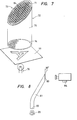
- Fig. 7 is a schematic drawing of an optical display system (72) that is composed of an array of the optical fiber devices of the present invention.
- individual optical devices (71) are arranged in such a manner that their light-radiating ends which are inclined at angle ⁇ relative to the fiber axes are in one cross-sectional plane to form an image display surface (73), whereas the other end of each optical fiber device is perpendicular to the fiber axis so as to form an image input surface (74).
- the assembly of the fibers is placed in a protective tubular sheath (75).
- the sheathed assembly When the sheathed assembly is positioned in such a way that the image input surface (74) is directed to a light source (76) with an image projecting filter (77) inserted therebetween, an enlarged image (78) will be produced on the display surface (73).
- the displayed image is very bright and features a wide visual angle.
- a display portion may be formed by embedding the inclined light-rediating ends of the optical fiber devices of the present invention at given spacings in a display panel of a given shape.
- One end of each fiber was cut to form a surface that was inclined by 30° relative to the fiber axis, and the other end was made perpendicular to the fiber axis.
- Two of the fibers were coated with a light-reflective layer on the outer periphery of the inclined end by two different methods, i.e., aluminum evaporation, application of a white paint (containing Ti0 2 as a reflective material).
- Another fiber was. coated with a black paint on the outer periphery of the inclined end, and the last fiber received no treatment at all.
- the luminance of light radiating from the so prepared four optical devices was measured with the configuration as shown in Fig. 8, in which the light-radiating end (83) of each device (81) was directed to luminance meter (84) (Spectral Radiometer Model SR-1 of Tokyo Kogaku Kikai K.K.) with the light-receiving end (82) facing a halogen lamp (85) (24 V, 150W).
- luminance meter (84) Spectral Radiometer Model SR-1 of Tokyo Kogaku Kikai K.K.
- a halogen lamp 24 V, 150W
- Example 2 Four pairs of plastic optical fibers that were of the same type as used in Example 1 were cut at one end to form surfaces that were inclined relative to the fiber axes at the angles indicated in Table 2. One fiber of each pair was coated with a white reflective layer on the fiber wall facing the inclined end, and the other member was provided with a light-absorbing black layer in the same area. The so prepared specimens were subjected to luminance measurement as in Example 1 and the results are summarized in Table 2.
- an optical fiber device of the present invention has a light radiating end that is inclined to the fiber axis and a light reflective layer is formed on the periphery of the radiating end, so that a wide visual angle of a display system without causing loss in the quantity of light propagating through the fiber can be attained.
- the fiber device of the present invention can be used for back illumination to a high luminance type display unit, display panel etc., and is useful in industry.
Abstract
Description
- The present invention relates to light transmitting optical fiber device. More particularly, the present invention relate to a light transmitting optical fiber device having its light radiating end shaped and constructed in a specified fashion and which can advantageously be used in an optical display system.
- A related art optical display system using an array of multiple optical fibers is shown in Japanese Patent Application Laid Open No. 198406/1984. In this system, optical fibers with their light radiating end surfaces formed perpendicular to the fiber axes are embedded in a certain array in a display panel and are bundled together at the other end which faces a light source. Each of the optical fibers with their light radiating end faces being perpendicular to the fiber axes has such a small diameter (10pm to a few mm) that the total cross-sectional area of the fibers that occupy the area in which a display is to be made is inevitably very small, and in order to fabricate an optical display unit having a desired display area, a huge number of optical fibers must be employed. Another problem associated with the use of optical fibers having their light radiating surfaces cut perpendicular to the fiber axes is that even if the fibers are made of plastics, the angle of light radiation form the fiber ends is not more than ±30° with respect to the optical axis and the resulting optical display is highly directive, rather than featuring a wide visual angle.
- Optical fiber display systems that are designed to maximize the area of display surface are shown in Japanese Patent Application Laid Open Nos. 86709/1986, 71782/1986 and U.S.P 4116739. The optical fiber array portion of these display systems is shown in Fig. 4 (perspective view) and in Fig. 5 (a crros-sectional view). Multiple optical fibers (41) arranged in the two directions of y-and z-axes are positioned to face a light source at one end so as to form an image receiving surface (44), with other end of the fiber array being inclined to the x-axis direction of fiber axis so as to provide an enlarged display surface (45). As shown in Fig. 4, an incident image (42) is displayed as an enlarged image (43) on the surface (45). As shown in Fig. 5, each of the incident rays (56) that encounter the image receiving surface (44) is guided through an individual optical fiber (51) in the direction of the arrow as it undergoes repeated internal reflection without escaping to the outside of the fiber, and emerges from the display surface (45). In this type of optical display system, the total cross-sectional area of the display surface is so large compared with the total cross-sectional area of the image receiving surface that the images provided by the individual fibers are not bright enough to produce a sharp overall display.
- As shown in Fig. 6(A), the angle of light radiation from an end (62) of an optical fiber (61) that is perpendicular to the fiber axis covers the range of +300. If the optical fiber has a light radiating end (63) which, as shown in Fig. 6(B), is inclined to the fiber axis, rays of light radiating from this end have high directivity in the direction of the fiber axis as illustrated by (64) and (65), with the result that the visual angle of the display system becomes narrower than in the case shown in Fig. 6(A). As a further problem, some of the rays of light propagating through the optical fiber (61) are reflected by the inclined radiating face (63) and the reflected ray (66) leaks from the fiber (61) by passing through the fiber wall (67) that is situated below the imaging surface. Because of this optical loss, the quantity of light radiating from the imaging surface is insufficient to produce a bright display.
- An object, therefore, of the present invention is to provide an improved optical fiber device having a light radiating end that provides a wide'visual angle without causing loss in the quantity of light propagating through the fiber.
- This object of the present invention can be attained by an optical fiber device composed of a core and a cladding, the core being made of an optical material having a refractive index nl, and the cladding being made of an optical material having a refractive index n2, the end of the optical fiber from which light radiates forming a plane that is inclined to the fiber axis by an angle θ,a light reflective layer being formed on the outer periphery of said radiating end, and the two refractive indices, nl and n2, satisfying the following relation (1):

- If the difference between n1 and n2 is less than 0.01, transmission loss occurs in the optical fiber, so that it is essential for the purpose of the present invention that relation nl - n2 ≧ 0.01 be satisfies in all cases.
- Fig. 1 is a perspective view of the light radiating portion of the optical fiber device according to a first embodiment of the present invention,
- Fig. 2 is a perspective view of the light radiating portion according to a second embodiment of the present invention,
- Fig. 3 is a sectional view of the optical fiber device illustrating the mechanism according to the present invention,
- Fig. 4 is a perspective view of a conventional display system,
- Fig. 5 is a sectional view of the conventional display system of Fig. 4,
- Figs. 6(A) and 6(B) are sectional views of conventional optical fibers, respectively,
- Fig. 7 is a schematic view of an optical display system using the optical fiber devices of the present invention, and
- Fig. 8 is a schematic view of the configuration for measuring the luminance of light from the optical devices of the present invention.
- The optical fibers for use in the optical device of the present invention may be formed from either silicate (quartz) systems or plastic systems but the latter systems are preferred since they are highly flexible and amenable to precise end preparation. Plastics, suitable for this purpose include: polymethyl methacrylate, polymethyl glutarimide (n = 1.49) and methyl methacrylate based copolymers (n = 1.47 - 1.50); polystyrene (n = 1.58) and styrenebased copolymers (n = 1.50 - 1.58); styrene/acrylonitrile copolymer (n = 1.56); poly-4-methylpentene-1 (n = 1.46); ethylene/vinylacetate copolymers (n = 1.46 - 1.50); polycarbonates (n = 1.50 - 1.57); polychlorostyrene (n = 1.61); polyvinylidene chloride (n = 1.63); polyvinyl acetate ( n = 1.47); methyl methacrylate/styrene (or vinyltoluehe or a-methylsyrene)/maleic anhydride terpolymer or quaternary polymer (n = 1.50 - 1.58); polydimethyl-siloxane (n = 1.40); polyacetal (n = 1.48); polytetrafluoroethylene (n = 1.35); polyvinylidene fluoride (n = 1.42); polytrifluoroethylene (n = 1.40); perfluoropropylene (n = 1.34); co- or terpolymers of fluoroethylene ( n = 1.35 - 1.40); blend polymers of polyvinylidene fluoride and polymethyl methacrylate (n = 1.42 - 1.46); polymers based on fluorinated methacrylates of the general formula CH2=C(CH3)COORf including those wherein Rf is - (CH2)m(CF2)ℓF (m = interger of 1 - 6; ℓ = integer of 1 - 10; n = 1.37 - 1.40), Rf is -(CH2)m(CF2)ℓH (m and ℓ are the same as defined above; n = 1.37 - 1.42), Rf is -CH(CF3)-2 (n = 1.38), Rf is -C(CF3)3 (n = 1.36), Rf is -CH2CF2CHFCF3 (n = 1.40), and Rf is -CH2CF(CF3)2 (n = 1.37); copolymers of these fluorinated methacrylates (n = 1.36 - 1.40); copolymers of these fluorinated methacrylates and methyl methacrylate (n = 1.37 - 1.43); polymers based on fluorinated acrylates of the general formula CH2=CH.COOR'f including those wherein R'f is -(CH2)m(CF2)eF (m and f are the same as defined above; n = 1.37 - 1.40), R'f is - (CH2)m(CF2)eH (m and f are the same as defined above; n = 1.37 - 1.40), R'f is -CH2CF2CHFCF3 (n = 1.41), and R'f is -CH(CF3)2 (n = 1.38); copolymers of these fluorinated acrylates (n = 1.36 - 1.41); copolymers of these fluorinated acrylates and the above mentioned fluorinated methacrylates ( n = 1,36 - 1.41); copolymers of these fluorinated acrylates, fluorinated methacrylates and methyl methacrylate (n = 1.37 - 1,43); homo- or copolymers ( n = 1.37 - 1.42) based on 2-fluoroacrylates of the general formula CH2=CF·COOR"f including those wherein Rf" is -CH3, -(CH2)m(CF2)nF, -(CH2)m(CF2)nH, -CH2CF2CHFCF3 AND - C(CF3)2; and fluorine-containing alkyl fumarate ester polymers (n - 1.30 - 1.42).
- These polymers may be appropriately combined to form a core and a cladding in optical fiber that satisfy the condition set forth by the relationship (1).
- Fig. 1 is a perspective view of the light radiating portion of the optical fiber device according to a first embodiment of the present invention:
reference numeral 11 denotes an optical fiber with a core-cladding structure; (12), a light reflective layer formed directly on the core surface of the fiber; (14), a light radiating surface that is inclined by an angle 0 with respect to the fiber axis; and (15), the cladding layer. - Fig. 2 is a perspective view showing a second embodiment of the light radiating portion: reference numeral (21) denotes an optical fiber; (24), a light radiating surface that is inclined by an angle 0 with respect to the fiber axis; (23), the cladding layer; and (22), a light reflective layer.
- The light reflective layer is formed on the outer periphery of the light-radiating end of each optical fiber by a suitable known technique such as sputtering, ion plating or coating with a light-reflective paint. If the sputtering or ion plating technique is employed, silver, nickel, aluminum or alloys thereof may be used as a light-reflective layer forming material and it is particularly preferable to use materials that absorb less of the intrinsic oscillation occurring in the visible range of the spectrum. If the light-reflective layer is formed by sputtering, a low-temperature sputtering apparatus is preferably employed in order to prevent the optical fiber being thermally damaged by the heat of condensation of the target metal or the radiation heat thereof.
- A suitable light-reflective paint is one which contains a titanium oxide, aluminum, nickel or silver powder as a light-reflective pigment.
- The mechanism by which the optical fiber device of the present invention enables light to emerge from the radiating end of each optical fiber without attenuation is shown schematically in Fig. 3, in which reference numeral (31) denotes the optical fiber device; (32), a ligh- reflective layer, (33), the cladding layer; (35), the core; and (34), the light-radiating end of the fiber which is inclined by an angle 6 with respect to the fiber axis. Rays of light (36) travelling straight through the fiber core are reflected by the inclined radiating surface (34) to change direction as indicated by (37) are further reflected by the reflective layer (32) and thereafter emerge from the radiating surface (34) as outgoing rays (39). In the absence of any leakage of light such as the one indicated by ray (66) in Fig. 6(B), the optical device of the present invention allows light with a very high degree of luminance to issue from its radiating end. In addition, the device is not only capable of changing the visual angle of light indicated by (64) and (65) in Fig. 6(B) but also of increasing such angle by means of the reflected light (39) shown in Fig. 3 Because of these advantages, the optical device displays an image that is discernible from a distant point and which can be seen over a wide visual angle.
- In the optical device of the present invention, the light-reflective layer is formed on at least the outer periphery of its light-radiating end. Preferably, this reflective layer is formed in such a region that the rays of light reflected from the radiating surface that is inclined at angle θ relative to the fiber axis are effectively reflected by this layer to emerge from said radiating surface. If desired, the reflective layer may be formed over the entire length of the optical fiber. Equally good results are attained even if the cladding layer is eliminated from that portion of the optical fiber where the reflective layer is to be formed. The smaller the angle 8, at which the light-radiating end of the optical fiber is inclined relative to the fiber axis, the larger the area of that radiating surface and hence the better. However, preferably, 0 is set at 70° or below, with the range of 5 - 60° being more preferable.
- Fig. 7 is a schematic drawing of an optical display system (72) that is composed of an array of the optical fiber devices of the present invention. As shown in the drawing, individual optical devices (71) are arranged in such a manner that their light-radiating ends which are inclined at angle θ relative to the fiber axes are in one cross-sectional plane to form an image display surface (73), whereas the other end of each optical fiber device is perpendicular to the fiber axis so as to form an image input surface (74). The assembly of the fibers is placed in a protective tubular sheath (75). When the sheathed assembly is positioned in such a way that the image input surface (74) is directed to a light source (76) with an image projecting filter (77) inserted therebetween, an enlarged image (78) will be produced on the display surface (73). The displayed image is very bright and features a wide visual angle.
- Alternatively, a display portion may be formed by embedding the inclined light-rediating ends of the optical fiber devices of the present invention at given spacings in a display panel of a given shape.
- Four plastic optical fibers (core: polymethyl methacrylate with n = 1.49; cladding: fluorinated alkyl methacrylate polymer with n = 1.42) produced by Mitsubishi Rayon Company Limited that had an outside diameter of 0.75 mm and a length of 1 m were used as starting materials. One end of each fiber was cut to form a surface that was inclined by 30° relative to the fiber axis, and the other end was made perpendicular to the fiber axis. Two of the fibers were coated with a light-reflective layer on the outer periphery of the inclined end by two different methods, i.e., aluminum evaporation, application of a white paint (containing Ti02 as a reflective material). Another fiber was. coated with a black paint on the outer periphery of the inclined end, and the last fiber received no treatment at all.
- The luminance of light radiating from the so prepared four optical devices was measured with the configuration as shown in Fig. 8, in which the light-radiating end (83) of each device (81) was directed to luminance meter (84) (Spectral Radiometer Model SR-1 of Tokyo Kogaku Kikai K.K.) with the light-receiving end (82) facing a halogen lamp (85) (24 V, 150W).
The result of measurement conducted at a frequency of 360 - 380 nm are shown in table 1.
- Four pairs of plastic optical fibers that were of the same type as used in Example 1 were cut at one end to form surfaces that were inclined relative to the fiber axes at the angles indicated in Table 2. One fiber of each pair was coated with a white reflective layer on the fiber wall facing the inclined end, and the other member was provided with a light-absorbing black layer in the same area. The so prepared specimens were subjected to luminance measurement as in Example 1 and the results are summarized in Table 2.

- As described above, an optical fiber device of the present invention has a light radiating end that is inclined to the fiber axis and a light reflective layer is formed on the periphery of the radiating end, so that a wide visual angle of a display system without causing loss in the quantity of light propagating through the fiber can be attained. The fiber device of the present invention can be used for back illumination to a high luminance type display unit, display panel etc., and is useful in industry.
Claims (5)
Applications Claiming Priority (2)
| Application Number | Priority Date | Filing Date | Title |
|---|---|---|---|
| JP9192586 | 1986-06-18 | ||
| JP91925/86 | 1986-06-18 |
Publications (2)
| Publication Number | Publication Date |
|---|---|
| EP0249934A2 true EP0249934A2 (en) | 1987-12-23 |
| EP0249934A3 EP0249934A3 (en) | 1990-06-06 |
Family
ID=14040161
Family Applications (1)
| Application Number | Title | Priority Date | Filing Date |
|---|---|---|---|
| EP87108628A Ceased EP0249934A3 (en) | 1986-06-18 | 1987-06-16 | Optical fiber device |
Country Status (3)
| Country | Link |
|---|---|
| US (1) | US4865417A (en) |
| EP (1) | EP0249934A3 (en) |
| KR (1) | KR880000807A (en) |
Cited By (7)
| Publication number | Priority date | Publication date | Assignee | Title |
|---|---|---|---|---|
| FR2631460A1 (en) * | 1988-05-11 | 1989-11-17 | Patiner Andre | Light waveguide plate for photocopier - has triangular optical fibres stuck in triangular flat structure and having lateral faces covered by absorbing substance |
| US4929048A (en) * | 1988-11-10 | 1990-05-29 | Fiberview Corporation | Fiber optic display |
| EP0478105A2 (en) * | 1990-09-25 | 1992-04-01 | Poly-Optical Products, Inc. | Fiber optic backlighting panel |
| GB2360603A (en) * | 2000-03-20 | 2001-09-26 | Cambridge 3D Display Ltd | Planar optical waveguide and float glass process |
| WO2005062089A1 (en) * | 2003-12-02 | 2005-07-07 | 3M Innovative Properties Company | Solid state light device |
| US7163327B2 (en) | 2002-12-02 | 2007-01-16 | 3M Innovative Properties Company | Illumination system using a plurality of light sources |
| US7189983B2 (en) | 2003-12-02 | 2007-03-13 | 3M Innovative Properties Company | LED modifying apparatus and method |
Families Citing this family (28)
| Publication number | Priority date | Publication date | Assignee | Title |
|---|---|---|---|---|
| US5257173A (en) * | 1989-12-13 | 1993-10-26 | Stanley Electric Co., Ltd. | Light irradiating apparatus having light emitting diode used as light source |
| US5046805A (en) * | 1990-07-16 | 1991-09-10 | Simon Jerome H | Tapered optical waveguides for uniform energy (light) distribution including energy bridging |
| US5037171A (en) * | 1990-08-30 | 1991-08-06 | The United States Of America As Represented By The Secretary Of The Air Force | Optical fiber coupling structure |
| US5253312A (en) * | 1992-06-26 | 1993-10-12 | Cytocare, Inc. | Optical fiber tip for use in a laser delivery system and a method for forming same |
| US5432876C1 (en) * | 1992-10-19 | 2002-05-21 | Minnesota Mining & Mfg | Illumination devices and optical fibres for use therein |
| US5659643A (en) * | 1995-01-23 | 1997-08-19 | Minnesota Mining And Manufacturing Company | Notched fiber array illumination device |
| US5631994A (en) * | 1995-08-23 | 1997-05-20 | Minnesota Mining And Manufacturing Company | Structured surface light extraction overlay and illumination system |
| US5905826A (en) * | 1996-01-24 | 1999-05-18 | Minnesota Mining And Manufacturing Co. | Conspicuity marking system including light guide and retroreflective structure |
| US6081638A (en) * | 1998-07-20 | 2000-06-27 | Honeywell Inc. | Fiber optic header with integrated power monitor |
| US6205274B1 (en) | 1998-07-20 | 2001-03-20 | Honeywell Inc. | Fiber optic header for an edge emitting laser |
| US6521989B2 (en) | 1998-10-08 | 2003-02-18 | Honeywell Inc. | Methods and apparatus for hermetically sealing electronic packages |
| US6195016B1 (en) | 1999-08-27 | 2001-02-27 | Advance Display Technologies, Inc. | Fiber optic display system with enhanced light efficiency |
| US6325551B1 (en) | 1999-12-08 | 2001-12-04 | New Focus, Inc. | Method and apparatus for optically aligning optical fibers with optical devices |
| US6632029B1 (en) | 1999-12-22 | 2003-10-14 | New Focus, Inc. | Method & apparatus for packaging high frequency components |
| JP2001183994A (en) * | 1999-12-27 | 2001-07-06 | Sony Corp | Image display device |
| US6792178B1 (en) | 2000-01-12 | 2004-09-14 | Finisar Corporation | Fiber optic header with integrated power monitor |
| EP1264298B1 (en) | 2000-03-06 | 2007-01-03 | Teledyne Lighting and Display Products, Inc. | Led light source with field-of-view-controlling optics |
| JP2003526190A (en) | 2000-03-06 | 2003-09-02 | テレダイン ライティング アンド ディスプレイ プロダクツ, インコーポレイテッド | Lighting device having quantum dot layer |
| US6379027B1 (en) | 2000-03-30 | 2002-04-30 | Ruud Lighting, Inc. | Light-generating and beam-establishing device |
| US6508579B1 (en) | 2000-05-09 | 2003-01-21 | Alan J. Ruud | Lighting apparatus for illuminating well-defined limited areas |
| US6637924B2 (en) * | 2000-11-15 | 2003-10-28 | Teledyne Lighting And Display Products, Inc. | Strip lighting apparatus and method |
| US6784603B2 (en) * | 2001-07-20 | 2004-08-31 | Teledyne Lighting And Display Products, Inc. | Fluorescent lighting apparatus |
| AU2003208394A1 (en) * | 2002-02-06 | 2003-09-02 | Screen Technology Limited | Display with optical fibre face plate |
| US6963682B2 (en) * | 2002-03-04 | 2005-11-08 | Corning Incorporated | Beam altering fiber lens device and method of manufacture |
| US6904197B2 (en) * | 2002-03-04 | 2005-06-07 | Corning Incorporated | Beam bending apparatus and method of manufacture |
| US20040018589A1 (en) * | 2002-07-25 | 2004-01-29 | Jun Zhong | Method for producing biologically active botulinum neurotoxins through recombinant DNA technique |
| US7099535B2 (en) * | 2002-12-31 | 2006-08-29 | Corning Incorporated | Small mode-field fiber lens |
| WO2007079263A2 (en) * | 2005-12-30 | 2007-07-12 | Vogley Wilbur C | Method and apparatus for eye-safe transmittal of electrical power in vehicles using white light via plastic optical fiber |
Citations (6)
| Publication number | Priority date | Publication date | Assignee | Title |
|---|---|---|---|---|
| US454704A (en) * | 1891-06-23 | bentley | ||
| US3402000A (en) * | 1964-09-10 | 1968-09-17 | Norman H. Crawford | Fiber optical image enlarger |
| US4045133A (en) * | 1975-06-13 | 1977-08-30 | Rca Corporation | Analog optical block processor |
| US4208096A (en) * | 1976-11-26 | 1980-06-17 | New York Institute Of Technology | Optical display apparatus |
| US4390589A (en) * | 1982-02-26 | 1983-06-28 | Bell Telephone Laboratories, Incorporated | Metal coating of fibers |
| US4647152A (en) * | 1982-09-29 | 1987-03-03 | Incom, Inc. | Optical apparatus |
Family Cites Families (5)
| Publication number | Priority date | Publication date | Assignee | Title |
|---|---|---|---|---|
| US4130343A (en) * | 1977-02-22 | 1978-12-19 | Bell Telephone Laboratories, Incorporated | Coupling arrangements between a light-emitting diode and an optical fiber waveguide and between an optical fiber waveguide and a semiconductor optical detector |
| US4423922A (en) * | 1978-12-18 | 1984-01-03 | The Boeing Company | Directional coupler for optical communications system |
| JPS5930502A (en) * | 1982-08-13 | 1984-02-18 | Nippon Telegr & Teleph Corp <Ntt> | Plastic optical fiber |
| US4715700A (en) * | 1982-09-29 | 1987-12-29 | Maurice Daniel | Light emitting optical fiber assemblies including light controlling |
| US4765701A (en) * | 1987-01-30 | 1988-08-23 | Poly-Optical Products, Inc. | Illuminator optical fiber rod |
-
1987
- 1987-06-16 EP EP87108628A patent/EP0249934A3/en not_active Ceased
- 1987-06-18 US US07/063,318 patent/US4865417A/en not_active Expired - Fee Related
- 1987-06-18 KR KR1019870006156A patent/KR880000807A/en not_active Application Discontinuation
Patent Citations (6)
| Publication number | Priority date | Publication date | Assignee | Title |
|---|---|---|---|---|
| US454704A (en) * | 1891-06-23 | bentley | ||
| US3402000A (en) * | 1964-09-10 | 1968-09-17 | Norman H. Crawford | Fiber optical image enlarger |
| US4045133A (en) * | 1975-06-13 | 1977-08-30 | Rca Corporation | Analog optical block processor |
| US4208096A (en) * | 1976-11-26 | 1980-06-17 | New York Institute Of Technology | Optical display apparatus |
| US4390589A (en) * | 1982-02-26 | 1983-06-28 | Bell Telephone Laboratories, Incorporated | Metal coating of fibers |
| US4647152A (en) * | 1982-09-29 | 1987-03-03 | Incom, Inc. | Optical apparatus |
Cited By (10)
| Publication number | Priority date | Publication date | Assignee | Title |
|---|---|---|---|---|
| FR2631460A1 (en) * | 1988-05-11 | 1989-11-17 | Patiner Andre | Light waveguide plate for photocopier - has triangular optical fibres stuck in triangular flat structure and having lateral faces covered by absorbing substance |
| US4929048A (en) * | 1988-11-10 | 1990-05-29 | Fiberview Corporation | Fiber optic display |
| EP0478105A2 (en) * | 1990-09-25 | 1992-04-01 | Poly-Optical Products, Inc. | Fiber optic backlighting panel |
| EP0478105A3 (en) * | 1990-09-25 | 1992-07-08 | Poly-Optical Products, Inc. | Fiber optic backlighting panel |
| GB2360603A (en) * | 2000-03-20 | 2001-09-26 | Cambridge 3D Display Ltd | Planar optical waveguide and float glass process |
| US7163327B2 (en) | 2002-12-02 | 2007-01-16 | 3M Innovative Properties Company | Illumination system using a plurality of light sources |
| WO2005062089A1 (en) * | 2003-12-02 | 2005-07-07 | 3M Innovative Properties Company | Solid state light device |
| US7189983B2 (en) | 2003-12-02 | 2007-03-13 | 3M Innovative Properties Company | LED modifying apparatus and method |
| US7202490B2 (en) | 2003-12-02 | 2007-04-10 | 3M Innovative Properties Company | LED modifying apparatus and method |
| US7250611B2 (en) | 2003-12-02 | 2007-07-31 | 3M Innovative Properties Company | LED curing apparatus and method |
Also Published As
| Publication number | Publication date |
|---|---|
| US4865417A (en) | 1989-09-12 |
| KR880000807A (en) | 1988-03-29 |
| EP0249934A3 (en) | 1990-06-06 |
Similar Documents
| Publication | Publication Date | Title |
|---|---|---|
| EP0249934A2 (en) | Optical fiber device | |
| DK158414B (en) | Back side PROJEKTIONSSKAERM | |
| US4021099A (en) | Optical couplers for fiber optic communication links | |
| US3907403A (en) | Fibre-optics faceplate observable with high-intensity ambient illumination | |
| EP0098578B1 (en) | Plastic optical fibers | |
| EP0307487B1 (en) | Collimator lens for optical fiber | |
| KR19990044014A (en) | Structural Light Extraction Overlay and Lighting System | |
| KR19990082141A (en) | Luminance Enhancer Film with Soft Cutoff | |
| GB2142157A (en) | Fiber optic light coupling assemblies | |
| JP2003530590A (en) | Planar optical waveguide for optical panel with gradient index core | |
| CA2254805C (en) | Optical fiber products having a stress indicating capability and process for making same | |
| US4189207A (en) | Deep focus fiber optic lens | |
| CA1189369A (en) | Image transmission line | |
| JP3020074B2 (en) | Illumination optical system | |
| EP0141037B1 (en) | Image transmission device | |
| US5274498A (en) | Optical system for a night vision video camera | |
| EP0141038B1 (en) | Image transmission path | |
| EP0068175A1 (en) | Image conducting fiber device | |
| CA1159691A (en) | Infrared light transmission path | |
| JPH0510647B2 (en) | ||
| EP1525501A1 (en) | A tapered optical fibre with a reflective coating at the tapered end | |
| CA2032353A1 (en) | Reusable mechanical connector for optical fibers | |
| Katagiri et al. | Optical microscope observation method of a single-mode optical-fiber core for precise core-axis alignment | |
| JPH0540180A (en) | Multiple-fiber optical sensor | |
| JPS63108243A (en) | Inspecting method for freaking of optical fiber cable |
Legal Events
| Date | Code | Title | Description |
|---|---|---|---|
| PUAI | Public reference made under article 153(3) epc to a published international application that has entered the european phase |
Free format text: ORIGINAL CODE: 0009012 |
|
| AK | Designated contracting states |
Kind code of ref document: A2 Designated state(s): BE DE FR GB IT |
|
| PUAL | Search report despatched |
Free format text: ORIGINAL CODE: 0009013 |
|
| AK | Designated contracting states |
Kind code of ref document: A3 Designated state(s): BE DE FR GB IT |
|
| 17P | Request for examination filed |
Effective date: 19901119 |
|
| 17Q | First examination report despatched |
Effective date: 19920302 |
|
| STAA | Information on the status of an ep patent application or granted ep patent |
Free format text: STATUS: THE APPLICATION HAS BEEN REFUSED |
|
| 18R | Application refused |
Effective date: 19950709 |
|
| RIN1 | Information on inventor provided before grant (corrected) |
Inventor name: YAMAMOTO,NAOHIROMITSUBISHI RAYON CO.,LTD. Inventor name: TOKUDA, SHUICHIROMITSUBISHI RAYON CO.,LTD. |