EP0249523A1 - Method of and apparatus for operating a thermal printing head - Google Patents
Method of and apparatus for operating a thermal printing head Download PDFInfo
- Publication number
- EP0249523A1 EP0249523A1 EP87401197A EP87401197A EP0249523A1 EP 0249523 A1 EP0249523 A1 EP 0249523A1 EP 87401197 A EP87401197 A EP 87401197A EP 87401197 A EP87401197 A EP 87401197A EP 0249523 A1 EP0249523 A1 EP 0249523A1
- Authority
- EP
- European Patent Office
- Prior art keywords
- heating
- duration
- cycles
- cycle
- during
- Prior art date
- Legal status (The legal status is an assumption and is not a legal conclusion. Google has not performed a legal analysis and makes no representation as to the accuracy of the status listed.)
- Granted
Links
Images


Classifications
-
- B—PERFORMING OPERATIONS; TRANSPORTING
- B41—PRINTING; LINING MACHINES; TYPEWRITERS; STAMPS
- B41J—TYPEWRITERS; SELECTIVE PRINTING MECHANISMS, i.e. MECHANISMS PRINTING OTHERWISE THAN FROM A FORME; CORRECTION OF TYPOGRAPHICAL ERRORS
- B41J2/00—Typewriters or selective printing mechanisms characterised by the printing or marking process for which they are designed
- B41J2/315—Typewriters or selective printing mechanisms characterised by the printing or marking process for which they are designed characterised by selective application of heat to a heat sensitive printing or impression-transfer material
- B41J2/32—Typewriters or selective printing mechanisms characterised by the printing or marking process for which they are designed characterised by selective application of heat to a heat sensitive printing or impression-transfer material using thermal heads
- B41J2/35—Typewriters or selective printing mechanisms characterised by the printing or marking process for which they are designed characterised by selective application of heat to a heat sensitive printing or impression-transfer material using thermal heads providing current or voltage to the thermal head
- B41J2/355—Control circuits for heating-element selection
Definitions
- the present invention firstly relates to a method of controlling a print head, or writing, thermal, of the serial type, for a printing system, in particular for a printer connected to a word processing device. .
- a thermal writing head generally comprises a plurality of heating elements, in general resistive elements arranged to be traversed by a current, and to cooperate either directly with a printing medium, heat-sensitive paper, or indirectly with a medium.
- ordinary printing by means of a ribbon coated with an ink melting with the heat of the elements. In the first case, it is a direct thermal printing, in the second case, a thermal transfer printing.
- the movable head comprises at least one bar, generally vertical, of elements, aligned in a direction orthogonal to the direction of rectilinear displacement, during the printing of a line of graphics, corresponding to the height of the bar, of a head support carriage.
- the set of heating elements that are heated during the same cycle obviously depends on the configuration of the transverse section of the line to be printed, of dimension L, equal to the product of the speed of displacement by the duration T of the cycles.
- the vertical definition depends only on the size and the spacing of the heating elements of the writing head.
- the horizontal definition is approximately inversely proportional to the speed of training of the head.
- the thermal inertia of a heating element it is not possible to make the interval of time during which it is hot enough to print as small as desired. This time interval is therefore bounded by a lower limit, the horizontal dimension of the "point" that it prints is therefore substantially inversely proportional to the speed of drive of the head.
- the present invention aims to provide a better compromise, that is to say, at constant writing speed, better horizontal definition or, with equivalent horizontal definition, greater writing speed.
- the present invention relates to a method of the type defined above, characterized in that the duration of the cycles is chosen at most equal to the duration of printing of the dots and that some of the heating elements are subjected to heating for a period starting in the middle of the cycles.
- the invention pre therefore sees being able to subject it, within the same cycle to a second heating.
- the heating element When the heating element is subjected to two successive heatings during the same cycle, it prints an "extended point".
- the start of this extended point coincides with the start of a normal point, but its length is greater than that of the normal point.
- the invention provides that it can only be subjected to heating from the middle of the cycle.
- the heating element prints an offset point.
- the start of this offset point is offset by half the width of a slice with respect to a normal point.
- the initial heating time and the heating time starting in the middle of the cycle are less than half the duration of a cycle.
- the offset point has the same length as the normal point and the extended point a length substantially equal to one and a half times the length of the normal point.
- the possible offset being equal to half a normal point length, we can say that we obtain a "pseudoresolution" double of the original resolution.
- a true double resolution would indeed suppose that the length of the point is divided by two, which is not the case.
- the duration (TI) of heating, during a first half-cycle, of a heating element determined is modulated so as to shorten this duration if this heating element has been heated during one of the two preceding half-cycles, and modulating the duration (TID) of heating, during a second half-cycle, of a determined heating element so as to shorten this duration if this heating element has been heated during one of the three preceding half-cycles.
- the writing head is provided with a first bar and a second transverse bar arranged one after the other in the longitudinal direction, and in which, at during an odd-order cycle, the heating elements of the second strip are not subjected to any heating, and, during an even-order cycle, the heating elements of the first strip are not subjected to any heating .
- a thermal print head 14 of serial type to print a line of characters 10 using a thermal print head 14 of serial type, the head 14 is moved in longitudinal displacement , here horizontal, along the line to be printed 10, in the direction of arrow 15, using a drive device which is not shown because it is conventional.
- Line 10 is broken down into a series of transverse sections 10a, 10b, ..., 10m, ... whose horizontal dimension is equal to the horizontal dimension, or length, L of an elementary point 100 that each of the heating elements 140 when it heats.
- the heating elements 140 are distributed along a transverse bar, here vertical, the height of which corresponds so at the height of the laundry 10.
- each section 10m is printed during a writing cycle the duration T of which is equal to the length L of a point 100, divided by the drive speed of the head 14.
- Each of the heating elements 140 is here a resistive element, accessible individually by connections not shown in FIG. 1, for the sake of simplicity. We will now describe the method of controlling one of these heating elements 140, the task of which is obviously to print a series of dots whose configuration depends on the line to be printed.
- each writing cycle of duration T is divided into two half-cycles of duration T / 2. It is expected to be able to heat, at the start of each half-cycle, the heating element considered for a duration TI for each first half-cycle and for a duration TID for each second half-cycle.
- the heating element is heated here by passing it through a current I so that, taking into account its thermal inertia, after heating for the duration TI or for the duration TID, its temperature 0 remains above a temperature of threshold 6 s for a time equal to T.
- the threshold temperature ⁇ s is that above which the paper is printed, the point printed by the heating element heated for a period TI or TID corresponds to the length L.
- the TI and TID durations of the heating phases are modulated so as to shorten them if the heated element is still hot at the start of each of these phases.
- the duration TI of heating during a first half-cycle takes the value T1 if the heating element has not been heated during any of the two half-cycles preceding this first half cycle; otherwise, the duration TI takes the value T2, with:
- the duration TID of heating during a second half-cycle takes the value TID if the heating element has not been heated during any of the three half-cycles preceding this second half-cycle; otherwise, the duration TID takes the value T2D, with:
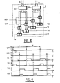
- FIG. 4 shows, by way of example, a certain number of configurations to be printed and the shape of the heating current I.
- FIG. 5 shows the result obtained in the case analogous to that of FIG. 3, of the writing of an uninterrupted series of normal points. It shows that the temperature remains below the maximum temperature ⁇ max .
- the writing head 14 being provided with a plurality of heating elements 140 distributed on a vertical bar, at each first half-cycle of a cycle, a first set of points is heated which corresponds to the configuration of the first half-section of the section to be written corresponding to the cycle considered, and each second half-cycle, a second set which corresponds to the configuration of the second half-section.
- the thermal stresses on the elements heating elements are quite severe, in particular when writing a continuous horizontal line where the temperature 6 must remain permanently above the writing threshold ⁇ s .
- the life of the heating elements, and therefore of the head is relatively short.
- the first strip 141 is active during write cycles of odd order, while it is at rest during write cycles of even order.
- the second strip 142 is active during write cycles of even order, and at rest during write cycles of odd order. That is to say that the first strip 141 prints only the odd-order sections, while the second strip 142 prints only the even-order sections.
- the writing is only complete after the passage of the two bars.
- the part common to the offset point and to the normal point does not present any difference in shade because all of the ink of the heat-sensitive paper, in the case of direct printing, or of the ribbon stationary relative to the paper, in the case of transfer printing, is released by the first heating element.
- the device shown in FIG. 8 is used, which receives on a bus 161 the data to be printed in the form of a digital signal and which controls the resistive elements 140 of the head 14 , including here a single bar of J elements.
- a clock 1 of known type delivers on three outputs three clock signals SYP, SYD and H.
- a sequence generator 2 receives the three signals SYP, SYD and H on three binary inputs and two digital signals, via two buses 21 and 22, on two digital inputs. It delivers on four binary outputs four sequential signals T1, T1D, T2 and T2D.
- a decoder circuit 16 receives the coded data in digital form, via the bus 161, on a digital input, as well as the signal SYP on a binary input. It delivers two groups of J binary output signals on two buses 31 and 32 of type parallel to J bits, that is to say each comprising J parallel conductors.
- a delay circuit 3 receives the signal SYP on a binary input and is connected to buses 31 and 32.
- the delay circuit 4 delivers three groups of J binary output signals tie on three buses 41, 42 and 43, of type parallel to J bits.
- a multiplexer 4 of known type, of which a digital control input is connected to the digital output of a counter 6 receives the signals from the three buses 41, 42 and 43, and delivers three binary output signals on three outputs 71, 72 and 73.
- the counter 6 is a modulo J counter, of known type, whose clock input receives the signal H and whose reset input receives the output signal from a detector 5 of the rising edges of the sequential signals T1, T1D, T2 and T2D, which it receives on four binary inputs.
- the counter 6 delivers a signal D on its overflow output.
- a circuit 7 for calculating the information to be printed is provided with three binary inputs connected to outputs 71, 72 and 73, and four binary inputs receiving the sequential signals T1, T1D, T2 and T2D. It delivers, on two binary outputs, two INF and CE output signals.
- a register 8 of the known type with serial input and parallel output at J bits, receives on a clock input, the signal H after passing through a logic gate 9 controlled by the signal D.
- the J conductors of the parallel output of the register 8 are connected to a buffer register 10 with parallel input and output, controlled by the signal D after passing through a shaping circuit 11.
- J conductors of the parallel output of register 10 are connected to J AND gates 12 of which the J other inputs receive the signal CE.
- each AND gate 12 is connected to the control input of a controllable switch 13 disposed between a first terminal of a supply circuit 150 delivering the voltage VP and a terminal of one of the J resistive heating elements 140, the other terminal of which is connected to the second terminal of the supply circuit 150.
- the supply circuit 150 also supplies electrical energy to all the elements of the preceding circuits, in a manner not shown for the sake of simplicity.
- Clock 1 delivers the signals SYP and SYD represented in FIG. 9, that is to say pulse trains with a frequency of recurrence equal to 1 / T and offset with respect to each other by T / 2.
- the signal H not shown, is a train of pulses like the signals SYP and SYD, but of much higher recurrence frequency.
- the sequential signals T1, T1D, T2 and T2D have the appearance shown in FIG. 9.
- the signals T1 and TID are at the high level for equal durations offset by T / 2, like the signals T2 and T2D.
- the duration of the sequence at the high level of the signal T2 is less than the duration of the sequence at the high level of the signal T1.
- the T1 and T2 signals go high during each pulse of the SYP signal.
- the TID and T2D signals go high on each pulse of the SYD signal.
- the decoder circuit 16 develops, as a function of the data it receives on the bus 161, two groups of J binary signals which possibly change with each pulse of the signal SYP.
- the J binary signals of the first group are:
- the J binary signals of the second group are:
- J type signals are transported by bus 31 and the J signals of the type are transported by bus 32.
- the delay circuit 3 delays these signals to deliver the three groups of J signals of the type , , and on the three buses 41, 42 and 43, respectively.
- the counter 6 After each rising edge of one of the sequential signals T1, T1D, T2 and T2D detected by the rising edge detector 5, the counter 6 is reset and controls, at the rate of the clock signal H the time multiplexing of the buses 41, 42 and 43 on binary outputs 71, 72 and 73.
- the circuit 7 for calculating the information to be printed calculates a binary signal INF which is at the high level if the heating element of rank j is to be heated and at the low level otherwise, for each of the four time intervals T2, (T1-T2), T2D, (T2D-T1D) of the range of rank (i - 1), so as to heat during time T1 or time T2, and during time TID or time T2D, depending, on the one hand, of the command for the range of rank (i - 1), and on the other hand of the state passed during the range of rank (i - 2) of this element, in accordance with the method described.
- the calculation circuit 7, from the seven signals applied to it, , , , T1, T1D, T2, T2D calculates the signal INF for the element of rank j as follows:
- the J values of the signal INF calculated one after the other by the calculation circuit 7 are stored in the series-parallel register 8, after each rising edge of one of the sequential signals T1, T1D, T2 and T2D , then transferred to the buffer register 10 which controls, via the AND gates 12, the heating of the heating elements 14.
- the AND gates cannot be turned on if the CE signal is at the high level.
- This signal CE is produced by the calculation circuit 7 to be at the low level when the signal T1 and the signal T1D are normally at the low level, so as to ensure, even in the event of a malfunction of the circuits placed upstream of the doors 12, for example if T1 or TID remain at the high level at the end of the current half-cycle, periodic cooling of the heating elements to avoid destruction.
- the current I which flows in each heating element 14 is here equal to the voltage VP divided by the value of the resistance of a heating element.
- the constitution of the sequence generator is shown in FIG. 10.
- Two registers 23 and 24 receive the digital signals present on the buses 21 and 22 which, as will be seen below, control the durations of the signals T 1 and TID of on the one hand and T2 and T2D on the other.
- the output of register 23 is applied to two gate circuits 25 controlled by the signals SYP and SYD.
- the output of register 24 is applied to two gate circuits 25, controlled by the signals SYP and SYD.
- Four counters 26, each provided with a clock input receiving the signal H and a parallel input receiving the output of one of the gates 25 deliver, on their four sign outputs, the signals T1, T1D, T2 and T2D .
- circuit 2 The operation of circuit 2 is as follows. Each counter 26 is mounted as a down-counter and its sign output is therefore positive, after having been loaded at the digital output value of the corresponding gate 25, only for a time which depends on this digital value.
- the signals shown in FIG. 9 are therefore obtained, the digital signal on the bus 21 controlling the duration, equal, of the signals T1 and TID and the digital signal on the bus 22 controlling the duration, equal, of the signals T2 and T2D.
- These durations can therefore be adjusted by the operator to adapt the device to the characteristics of the heating elements of the writing head, by modifying the digital signals applied to the buses 21 and 22.
- the decoder circuit 16 includes a memory which contains the different bit sequences and corresponding to the various alphanumeric characters to be written, the print quality of which will obviously be better, taking into account the particular possibilities of the process of the invention of printing an offset point and an extended point.
- This memory is addressed by addressing circuits of known type, in response to the coded data received on the bus 161.
- the decoder circuit is therefore of known type, within the reach of those skilled in the art and will not be described further.
- the delay circuit 3 is shown in FIG. 11. It comprises on the one hand three buffer registers 34, 35 and 36 connected in cascade between the bus 31 and the bus 42 and on the other hand two buffer registers 37 and 38 connected in cascade between bus 32 and bus 43.
- a shaping circuit 330 the input of which receives the signal SYP, delivers at the output a signal which controls, on the one hand, a circuit of doors 333 interposed upstream of the register 36, and on the other hand, and after passing through a delay line 331, two gate circuits 332 each interposed upstream of the registers 35 and 38.
- the delay of the delay line 331 corresponds to the time necessary to transfer the data from one register like register 34 to the next like register 35, via a circuit of doors 332.
- the bus 41 is connected in bypass to the output of register 35, upstream of door 333. The operation of a such a circuit is obvious to those skilled in the art.
- the rising edge detector 5, as well as the circuit 7 for calculating the information to be printed, are entirely conventional combinational logic circuits, the design of which is within the reach of those skilled in the art, and will not be further described.
- each of the bars is controlled by a device identical to that of FIG. 8, except that a single decoder 16, common to the two devices, is used .
- the heating current I of the resistive elements is constant and its duration of application variable.
- the durations of the sequences at the high level of the signals T1 and TID on the one hand, T2 and T2D on the other hand are equal. Furthermore, these durations are less than the duration T / 2 of a half-cycle.
- the durations of the sequences at the high level of the signals T1, T1D, T2 and T2D can be chosen as desired, while remaining less than the duration T of a cycle, in the cases where the head can withstand the resulting thermal stresses and where we don't try to get points of constant length.
- heating system by current flow in a resistive element can be replaced by any other heating system, for example by radiation, which may be suitable for thermal printing.
Abstract
ne tête d'impression thermique de type série est commandée à la volée, au cours d'une suite de cycles de durée au plus égale à la durée d'impression des points, pour pouvoir être chauffée indépendamment au cours de la première moitié et au cours de la deuxième moitié de chaque cycle. On peut ainsi imprimer un point décalé de la demi-longueur d'un point normal, ou un point prolongé, une fois et demie plus long que le point normal, pour améliorer la définition de l'impression sans réduire la vitesse d'écriture.L'invention s'applique aux systèmes d'impression, notamment pour imprimante reliée à un dispositif de traitement de textes.a series-type thermal print head is controlled on the fly, during a series of cycles of duration at most equal to the printing duration of the dots, to be able to be heated independently during the first half and the during the second half of each cycle. It is thus possible to print a dot offset by half the length of a normal dot, or an extended dot, one and a half times longer than the normal dot, to improve the definition of the print without reducing the writing speed. The invention applies to printing systems, in particular for a printer connected to a word processing device.
Description
La présente invention a tout d'abord pour objet un procédé de commande d'une tête d'impression, ou d'écriture, thermique, de type série, pour système d'impression, notamment pour imprimante reliée à un dispositif de traitement de textes.The present invention firstly relates to a method of controlling a print head, or writing, thermal, of the serial type, for a printing system, in particular for a printer connected to a word processing device. .
Une tête thermique d'écriture comporte généralement une pluralité d'éléments chauffants, en général des éléments résistifs agencés pour être parcourus par un courant, et coopérer soit directement avec un support d'impression, un papier thermosensible, soit indirectement avec un support d'impression ordinaire, par l'intermédiaire d'un ruban enduit d'une encre fondant à la chaleur des éléments. Dans le premier cas, il s'agit d'une impression thermique directe, dans le second cas, d'une impression par transfert thermique.A thermal writing head generally comprises a plurality of heating elements, in general resistive elements arranged to be traversed by a current, and to cooperate either directly with a printing medium, heat-sensitive paper, or indirectly with a medium. ordinary printing, by means of a ribbon coated with an ink melting with the heat of the elements. In the first case, it is a direct thermal printing, in the second case, a thermal transfer printing.
Il s'agit ici d'une impression thermique de type série, et dans ce cas, la tête, mobile, comporte au moins une barrette, généralement verticale, d'éléments, alignés selon une direction orthogonale au sens du déplacement rectiligne, durant l'impression d'une ligne de graphismes, correspondant à la hauteur de la barrette, d'un chariot-support de la tête.This is a series type thermal printing, and in this case, the movable head comprises at least one bar, generally vertical, of elements, aligned in a direction orthogonal to the direction of rectilinear displacement, during the printing of a line of graphics, corresponding to the height of the bar, of a head support carriage.
Plus particulièrement, l'invention concerne un procédé de commande d'une tête d'écriture thermique de type série pour imprimante, pourvue d'une barrette d'éléments chauffants, dans lequel,
- - on entraine ladite tête en déplacement longitudinal le long d'une ligne à imprimer, à une vitesse déterminée,
- - les éléments chauffants étant soumis à des cycles thermiques comprenant, chacun, une durée de chauffage initial et une durée de refroidissement pour imprimer des points.
- said head is driven in longitudinal displacement along a line to be printed, at a determined speed,
- - The heating elements being subjected to thermal cycles each comprising an initial heating time and a cooling time to print dots.
Dans ce procédé, l'ensemble d'éléments chauffants que l'on fait chauffer au cours d'un même cycle dépend évidemment de la configuration de la tranche transversale de la ligne à imprimer, de dimension L, égale au produit de la vitesse de déplacement par la durée T des cycles.In this process, the set of heating elements that are heated during the same cycle obviously depends on the configuration of the transverse section of the line to be printed, of dimension L, equal to the product of the speed of displacement by the duration T of the cycles.
Dans un tel procédé, et en se placant par exemple dans le cas extrêmement fréquent où la ligne est écrite horizontalement, la définition verticale dépend uniquement de la taille et de l'espacement des éléments chauffants de la tête d'écriture. Par contre, la définition horizontale est approximativement inversement proportionnelle à la vitesse d'entrainement de la tête. En effet, compte tenu de l'inertie thermique d'un élément chauffant, il n'est pas possible de rendre aussi petit que l'on veut l'intervalle de temps pendant lequel il est assez chaud pour imprimer. Cet intervalle de temps étant donc borné par une limite inférieure, la dimension horizontale du "point" qu'il imprime est donc sensiblement inversement proportionnelle à la vitesse d'entrainement de la tête.In such a method, and taking place for example in the extremely frequent case where the line is written horizontally, the vertical definition depends only on the size and the spacing of the heating elements of the writing head. On the other hand, the horizontal definition is approximately inversely proportional to the speed of training of the head. In fact, taking into account the thermal inertia of a heating element, it is not possible to make the interval of time during which it is hot enough to print as small as desired. This time interval is therefore bounded by a lower limit, the horizontal dimension of the "point" that it prints is therefore substantially inversely proportional to the speed of drive of the head.
Dans le procédé défini ci-dessus, on doit donc réaliser un compromis entre la définition horizontale et la rapidité d'écriture de la tête.In the process defined above, a compromise must therefore be made between the horizontal definition and the speed of writing the head.
La présente invention vise à procurer un meilleur compromis, c'est-à-dire, à rapidité d'écriture constante, une meilleure définition horizontale ou, à définition horizontale équivalente, une plus grande rapidité d'écriture.The present invention aims to provide a better compromise, that is to say, at constant writing speed, better horizontal definition or, with equivalent horizontal definition, greater writing speed.
A cet effet, la présente invention concerne un procédé du type défini ci-dessus, caractérisé par le fait qu'on choisit la durée des cycles au plus égale à la durée d'impression des points et qu'on soumet certains des éléments chauffants à un chauffage pendant une durée commençant au milieu des cycles.To this end, the present invention relates to a method of the type defined above, characterized in that the duration of the cycles is chosen at most equal to the duration of printing of the dots and that some of the heating elements are subjected to heating for a period starting in the middle of the cycles.
Dans le cas où un élément chauffant est soumis à un chauffage initial pendant une durée non nulle, l'invention prévoit donc de pouvoir le soumettre, à l'intérieur du même cycle à un deuxième chauffage.In the case where a heating element is subjected to an initial heating for a non-zero duration, the invention pre therefore sees being able to subject it, within the same cycle to a second heating.
Quant l'élément chauffant est soumis à deux chauffages successifs au cours d'un même cycle, il imprime un "point prolongé". Le début de ce point prolongé coincide avec le début d'un point normal, mais sa longueur est plus grande que celle du-point normal.When the heating element is subjected to two successive heatings during the same cycle, it prints an "extended point". The start of this extended point coincides with the start of a normal point, but its length is greater than that of the normal point.
Au contraire, si la durée initiale de chauffage d'un élément est nulle, à l'intérieur d'un cycle, l'invention prévoit de ne pouvoir le soumettre à un chauffage qu'à partir du milieu du cycle. Dans ce dernier cas, l'élément chauffant imprime un point décalé. Le début de ce point décalé est décalé de la moitié de la largeur d'une tranche par rapport à un point normal.On the contrary, if the initial heating time of an element is zero, within a cycle, the invention provides that it can only be subjected to heating from the middle of the cycle. In the latter case, the heating element prints an offset point. The start of this offset point is offset by half the width of a slice with respect to a normal point.
On constate donc que, sans réduction de la vitesse d'en- trainement de la tête, celle-ci est capable d'imprimer à la volée, en plus d'un point normal, un point décalé et un point prolongé. Ceci permet d'obtenir une amélioration de la définition horizontale de chaque ligne, qui donne une meilleure qualité d'impression, en particulier en ce qui concerne la reproduction des barres obliques fréquemment rencontrées dans les caractères alpha-numériques. Compte tenu du fait que celles-ci sont plus faiblement inclinées par rapport à la verticale que par rapport à l'horizontale, le fait que la résolution verticale reste inchangée, et le fait que la dimension horizontale du point n'est pas réduite ont une influence peu perceptible sur la qualité finale de l'impression.It can therefore be seen that, without reducing the head drive speed, it is capable of printing on the fly, in addition to a normal point, an offset point and an extended point. This makes it possible to obtain an improvement in the horizontal definition of each line, which gives a better print quality, in particular with regard to the reproduction of the slashes frequently encountered in alpha-numeric characters. Taking into account that these are more slightly inclined with respect to the vertical than with respect to the horizontal, the fact that the vertical resolution remains unchanged, and the fact that the horizontal dimension of the point is not reduced have a little noticeable influence on the final quality of the print.
Dans la mise en oeuvre préférée du procédé de l'invention, la durée de chauffage initial et la durée du chauffage commençant au milieu du cycle sont inférieures à la moitié de la durée d'un cycle.In the preferred implementation of the method of the invention, the initial heating time and the heating time starting in the middle of the cycle are less than half the duration of a cycle.
Dans ce cas, le point décalé a la même longueur que le point normal et le point prolongé une longueur sensiblement égale à une fois et demie la longueur du point normal. Le décalage possible étant égal à la moitié d'une longueur de point normal, on peut dire qu'on obtient une "pseudorésolution" double de la résolution primitive. Une vraie résolution double supposerait en effet que la longueur du point se trouve divisée par deux, ce qui n'est pas le cas.In this case, the offset point has the same length as the normal point and the extended point a length substantially equal to one and a half times the length of the normal point. The possible offset being equal to half a normal point length, we can say that we obtain a "pseudoresolution" double of the original resolution. A true double resolution would indeed suppose that the length of the point is divided by two, which is not the case.
Avantageusement, on module la durée (TI) du chauffage, pendant un premier demi-cycle, d'un élément chauffant déterminé de façon à raccourcir cette durée si cet élément chauffant a été chauffé au cours d'un des deux demi-cycles précédents, et on module la durée (TID) du chauffage, pendant un deuxième demi-cycle, d'un élément chauffant déterminé de façon à raccourcir cette durée si cet élément chauffant a été chauffé au cours d'un des trois demi-cycles précédents.Advantageously, the duration (TI) of heating, during a first half-cycle, of a heating element determined is modulated so as to shorten this duration if this heating element has been heated during one of the two preceding half-cycles, and modulating the duration (TID) of heating, during a second half-cycle, of a determined heating element so as to shorten this duration if this heating element has been heated during one of the three preceding half-cycles.
Dans une autre mise en oeuvre du procédé de l'invention, la tête d'écriture est pourvue d'une première barrette et d'une deuxième barrette transversales disposées l'une après l'autre dans le sens longitudinal, et dans lequel, au cours d'un cycle d'ordre impair, les éléments chauffants de la deuxième barrette ne sont soumis à aucun chauffage, et, au cours d'un cycle d'ordre pair, les éléments chauffants de la première barrette ne sont soumis à aucun chauffage.In another implementation of the method of the invention, the writing head is provided with a first bar and a second transverse bar arranged one after the other in the longitudinal direction, and in which, at during an odd-order cycle, the heating elements of the second strip are not subjected to any heating, and, during an even-order cycle, the heating elements of the first strip are not subjected to any heating .
L'invention a également pour objet un dispositif pour la mise en oeuvre du procédé de l'invention, comprenant
- - des moyens pour entrainer ladite tête en déplacement longitudinal le long d'une ligne à imprimer, à une vitesse déterminée,
- - des moyens de chauffage desdits éléments chauffants,
- - des moyens de calcul de la durée du chauffage commandant lesdits moyens de chauffage, pour soumettre lesdits éléments chauffants à des cycles thermiques comprenant, chacun, une durée de chauffage initial et une durée de refroidissement, pour imprimer des points,
dispositif caractérisé par le fait que - - les moyens de calcul comprennent des moyens pour ajuster la durée des cycles à une durée au plus égale à la durée d'impression des points, des moyens pour déterminer certains éléments chauffants devant être soumis à un chauffage à partir du milieu des cycles, et sont agencés pour commander lesdits moyens de chauffage pour soumettre lesdits éléments chauffants déterminés à un chauffage pendant une durée commençant au milieu des cycles.
L'invention sera mieux comprise à l'aide de la description suivante de la mise en oeuvre préférée du procédé, et de la forme de réalisation préférée du dispositif de l'invention, faite en se référant aux dessins annexés, sur lesquels, - - la figure 1 représente" sChématiquement une ligne de caractères en cours d'impression par une première tête d'écriture,
- - la figure 2 représente un premier diagramme temporel du courant de commande, de la température et de l'écriture associée d'un élément chauffant de la tête de la figure 1,
- - la figure 3 représente un deuxième diagramme temporel du type de celui de la figure 2,
- - la figure 4 représente six diagrammes temporels de six courants de commande, et les six écritures associées d'un élément chauffant de la tête de la figure 1,
- - la figure 5 représente un troisième diagramme temporel du type de celui de la figure 2,
- - la figure 6 représente schématiquement une ligne de caractères en cours d'impression par une deuxième tête d'écriture,
- - la figure 7 représente la configuration d'un "point prolongé décalé" imprimable par la tête de la figure 6,
- - la figure 8 représente un schéma par blocs d'un dispositif de commande de la tête de la figure 1,
- - la figure 9 représente un diagramme temporel de signaux d'entrée et de sortie du générateur de séquences du dispositif de la figure 8,
- - la figure 10 représente un schéma détaillé du générateur de séquences du dispositif de la figure 8, et,
- - la figure 11 représente un schéma détaillé du circuit retardateur du dispositif de la figure 8.
- means for driving said head in longitudinal displacement along a line to be printed, at a determined speed,
- means for heating said heating elements,
- - means for calculating the duration of the controlling heating said heating means, for subjecting said heating elements to thermal cycles each comprising an initial heating time and a cooling time, for printing dots,
device characterized by the fact that - the calculation means comprise means for adjusting the duration of the cycles to a duration at most equal to the duration of printing of the dots, means for determining certain heating elements to be subjected to heating from the middle of the cycles, and are arranged to control said heating means to subject said determined heating elements to heating for a period starting in the middle of the cycles.
The invention will be better understood with the aid of the following description of the preferred implementation of the method, and of the preferred embodiment of the device of the invention, made with reference to the appended drawings, in which, - FIG. 1 represents "schematically a line of characters being printed by a first writing head,
- FIG. 2 represents a first time diagram of the control current, of the temperature and of the associated writing of a heating element of the head of FIG. 1,
- FIG. 3 represents a second time diagram of the type of that of FIG. 2,
- FIG. 4 represents six time diagrams of six control currents, and the six associated entries of a heating element of the head of FIG. 1,
- - Figure 5 shows a third time diagram of the type of that of FIG. 2,
- FIG. 6 schematically represents a line of characters being printed by a second writing head,
- FIG. 7 represents the configuration of an "offset extended point" printable by the head of FIG. 6,
- FIG. 8 represents a block diagram of a device for controlling the head of FIG. 1,
- FIG. 9 represents a time diagram of input and output signals of the sequence generator of the device of FIG. 8,
- FIG. 10 represents a detailed diagram of the sequence generator of the device of FIG. 8, and,
- FIG. 11 represents a detailed diagram of the delay circuit of the device of FIG. 8.
En référence à la figure 1, dans une imprimante de transmission de données, par exemple, pour imprimer une ligne de caractères 10 à l'aide d'une tête d'impression thermique 14 de type série, on entraine la tête 14 en déplacement longitudinal, ici horizontal, le long de la ligne à imprimer 10, dans le sens de la flèche 15, à l'aide d'un dispositif d'entrainement non représenté car classique.With reference to FIG. 1, in a data transmission printer, for example, to print a line of
La ligne 10 est décomposée en une suite de tranches transversales 10a, 10b, ..., 10m, ... dont la dimension horizontale est égale à la dimension horizontale, ou longueur, L d'un point élémentaire 100 que peut imprimer chacun des éléments chauffants 140 lorsqu'il chauffe. Les éléments chauffants 140 sont répartis le long d'une barrette transversale, ici verticale, dont la hauteur correspond donc à la hauteur de la linge 10.
Ainsi, chaque tranche 10m est imprimée au cours d'un cycle d'écriture dont la durée T est égale à la longueur L d'un point 100, divisée par la vitesse d'entrainement de la tête 14.Thus, each
Chacun des éléments chauffants 140 est ici un élément résistif, accessible individuellement par des connexions non représentées sur la figure 1, par souci de simplicité. On décrit maintenant le procédé de commande d'un de ces éléments chauffants 140, dont la tâche est évidemment d'imprimer une suite de points dont la configuration dépend de la ligne à imprimer.Each of the
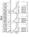
En référence à la figure 2, chaque cycle d'écriture de durée T est divisé en deux demi-cycles de durée T/2. On prévoit de pouvoir faire chauffer, au début de chaque demi-cycle, l'élément chauffant considéré pendant une durée TI pour chaque premier demi-cycle et pendant une durée TID pour chaque deuxième demi-cycle.With reference to FIG. 2, each writing cycle of duration T is divided into two half-cycles of duration T / 2. It is expected to be able to heat, at the start of each half-cycle, the heating element considered for a duration TI for each first half-cycle and for a duration TID for each second half-cycle.
On fait chauffer ici l'élément chauffant en le faisant parcourir par un courant I de façon à ce que, compte tenu de son inertie thermique, après chauffage pendant la durée TI ou pendant la durée TID, sa température 0 reste supérieure à une température de seuil 6s pendant un temps égal à T. Comme la température de seuil θs est celle au-delà de laquelle le papier est imprimé, le point imprimé par l'élément chauffant chauffé pendant une durée TI ou TID correspond à la longueur L.The heating element is heated here by passing it through a current I so that, taking into account its thermal inertia, after heating for the duration TI or for the duration TID, its
Comme le montre la figure 2, on dispose de quatre possibilités de commande pour chaque cycle. Ces quatre possibilités sont :
- a) aucun chauffage :
- pas d'impression
- b) chauffage pendant le premier demi-cycle seulement : impression d'un point normal de longueur L
- c) chauffage pendant le deuxième demi-cycle seulement : impression d'un point décalé de longueur L
- d) chauffage pendant les deux demi-cycles : impression d'un point prolongé de longueur légèrement supérieure à 1,5L.
- a) no heating:
- no printing
- b) heating during the first half cycle only: printing of a normal point of length L
- c) heating during the second half cycle only: printing of an offset point of length L
- d) heating during the two half-cycles: printing of an extended point of length slightly greater than 1.5L.
En effet, dans ce dernier cas d) le fait que l'élément chauffant se trouve chauffé au cours du premier demi-cycle a pour conséquence le fait que la température atteinte pendant le deuxième demi-cycle, au bout du temps TID est supérieure à celle atteinte au même moment dans le cas c), par exemple. Il en résulte d'une part un risque de voir la température dépasser la valeur maximale θmax admissible par l'élément chauffant, et d'autre part, un trainage de l'écriture du point prolongé, qui va être un peu plus long que 1,5L.Indeed, in the latter case d) the fact that the heating element is heated during the first half-cycle results in the fact that the temperature reached during the second half-cycle, at the end of the time TID is greater than that reached at the same time in case c), for example. This results on the one hand in a risk of seeing the temperature exceed the maximum value θ max admissible by the heating element, and on the other hand, a dragging of the writing of the extended point, which will be a little longer than 1.5L.
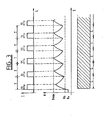
Un tel inconvénient se rencontre dans d'autres situations, et, en particulier lors de l'écriture d'une suite ininterrompue de points normaux, comme le montre la figure 3. Sur cette figure, le fait que la température 6 de l'élément chauffant n'est pas encore retombée à la température ambiante A à la fin d'un cycle d'écriture pendant lequel un point a été effectivement imprimé a pour conséquence une augmentation cumulative de la température de cycle en cycle et un dépassement inadmissible de la température maximale θmax·Such a drawback is encountered in other situations, and, in particular when writing an unbroken series of normal points, as shown in FIG. 3. In this figure, the fact that the temperature 6 of the element heating has not yet returned to room temperature A at the end of a writing cycle during which a dot has actually been printed results in a cumulative increase in temperature from cycle to cycle and an unacceptable temperature overshoot maximum θ max ·
Pour pallier cet inconvénient, on module les durées TI et TID des phases de chauffage de façon à les raccourcir si l'élément chauffé est encore chaud au début de chacune de ces phases. Ainsi, la durée TI de chauffage pendant un premier demi-cycle prend la valeur T1 si l'élément chauffant n'a été chauffé au cours d'aucun des deux demi-cycles précédents ce premier demi-cycle ; dans le cas contraire, la durée TI prend la valeur T2, avec :![]()
![]()
De même, la durée TID de chauffage pendant un deuxième demi-cycle prend la valeur TID si l'élément chauffant n'a été chauffé au cours d'aucun des trois demi-cycles précédents ce deuxième demi-cycle ; dans le cas contraire, la durée TID prend la valeur T2D, avec :![]()

![]()
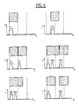
La figure 4 montre, à titre d'exemple, un certain nombre de configurations à imprimer et l'allure du courant de chauffage I.FIG. 4 shows, by way of example, a certain number of configurations to be printed and the shape of the heating current I.
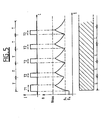
La figure 5 montre le résultat obtenu dans le cas analogue à celui de la figure 3, de l'écriture d'une suite ininterrompue de points normaux. Elle montre que la température reste inférieure à la température maximale θmax.FIG. 5 shows the result obtained in the case analogous to that of FIG. 3, of the writing of an uninterrupted series of normal points. It shows that the temperature remains below the maximum temperature θ max .
Bien sûr, la tête d'écriture 14 étant pourvue d'une pluralité d'éléments chauffants 140 répartis sur une barrette verticale, à chaque premier demi-cycle d'un cycle, on chauffe un premier ensemble de points qui correspond à la configuration de la première demi-tranche de la tranche à écrire correspondant au cycle considéré, et à chaque second demi-cycle, un second ensemble qui correspond à la configuration de la deuxième demi-tranche.Of course, the writing
Dans la mise en oeuvre du procédé de l'invention qui vient d'être décrite, les contraintes thermiques sur les éléments chauffants sont assez sévères, en particulier lors de l'écriture d'une ligne horizontale continue où la température 6 doit rester en permanence supérieure au seuil d'écriture θs. Il en résulte que la durée de vie des éléments chauffants, et donc de la tête, est relativement courte. Pour éviter cet inconvénient, on peut, de manière connue, et comme le montre la figure 6, utiliser une tête 14' pourvue de deux barrettes transversales 141 et 142, disposées l'uneaprès l'autre dans le sens longitudinal, et distantes d'une longueur D égale à un nombre pair de fois la longueur L :
Dans ce cas, la première barrette 141 est active lors des cycles d'écriture d'ordre impair, tandis qu'elle est au repos lors des cycles d'écriture d'ordre pair. Par contre la deuxième barrette 142 est active lors des cycles d'écriture d'ordre pair, et au repos lors des cycles d'écriture d'ordre impair. C'est-à-dire que la première barrette 141 n'imprime que les tranches d'ordre impair, alors que la deuxième barrette 142 n'imprime que les tranches d'ordre pair. Naturellement, comme le montre la figure 6, l'écriture n'est complète qu'après passage des deux barrettes.In this case, the first strip 141 is active during write cycles of odd order, while it is at rest during write cycles of even order. On the other hand, the second strip 142 is active during write cycles of even order, and at rest during write cycles of odd order. That is to say that the first strip 141 prints only the odd-order sections, while the second strip 142 prints only the even-order sections. Naturally, as shown in FIG. 6, the writing is only complete after the passage of the two bars.
Il en résulte que chaque cycle d'écriture au cours duquel un élément a chauffé est obligatoirement suivi d'un cycle d'écriture au cours duquel il pourra se refroidir. Les contraintes thermiques sont donc réduite et la durée de vie augmentée.As a result, each writing cycle during which an element has heated is necessarily followed by a writing cycle during which it can cool. The thermal stresses are therefore reduced and the service life increased.
Par ailleurs, en considérant une tranche déterminée, si l'on commande à la barrette qui imprime cette tranche d'imprimer un point décalé, et à l'autre barrette d'imprimer un point normal à la même hauteur que ce point décalé sur la tranche suivante, on obtient une cinquième possibilité f) d'impression, qui est le "point décalé prolongé" représenté sur la figure 7.Furthermore, considering a determined slice, if we order the bar that prints this slice to print an offset point, and the other bar to print a normal point at the same height as this point offset on the slice next, a fifth printing possibility f) is obtained, which is the "extended offset point" represented in FIG. 7.
Compte tenu du principe même de l'impression thermique, la partie commune au point décalé et au point normal ne présente aucune différence de teinte car la totalité de l'encre du papier thermosensible, dans le cas d'une impression directe, ou du ruban immobile par rapport au papier, dans le cas d'une impression par transfert, est libérée par le premier élément chauffant.Taking into account the very principle of thermal printing, the part common to the offset point and to the normal point does not present any difference in shade because all of the ink of the heat-sensitive paper, in the case of direct printing, or of the ribbon stationary relative to the paper, in the case of transfer printing, is released by the first heating element.
Pour la mise en oeuvre du procédé de l'invention, on utilise le dispositif représenté sur la figure 8, qui reçoit sur un bus 161 les données à imprimer sous forme d'un signal numérique et qui commande les éléments résistifs 140 de la tête 14, comprenant ici une unique barrette de J éléments.For the implementation of the method of the invention, the device shown in FIG. 8 is used, which receives on a
En se référant donc à la figure 8, une horloge 1 de type connu délivre sur trois sorties trois signaux d'horloges SYP, SYD et H.Referring therefore to FIG. 8, a
Un générateur de séquences 2 reçoit les trois signaux SYP, SYD et H sur trois entrées binaires et deux signaux numériques, via deux bus 21 et 22, sur deux entrées numériques. Il délivre sur quatre sorties binaires quatre signaux séquentiels T1, T1D, T2 et T2D.A
Un circuit décodeur 16 reçoit les données codées sous forme numérique, via le bus 161, sur une entrée numérique, ainsi que le signal SYP sur une entrée binaire.Il délivre deux groupes de J signaux binaires de sortie sur deux bus 31 et 32 de type parallèle à J bits, c'est-à-dire comprenant chacun J conducteurs parallèles.A
Un circuit retardateur 3 reçoit le signal SYP sur une entrée binaire et est connecté aux bus 31 et 32. Le circuit retardateur 4 délivre trois groupes de J signaux binaires de sortie sur trois bus 41, 42 et 43, de type parallèle à J bits.A delay circuit 3 receives the signal SYP on a binary input and is connected to
Un multiplexeur 4, de type connu, dont une entrée numérique de commande est connectée à la sortie numérique d'un compteur 6 reçoit les signaux des trois bus 41, 42 et 43, et délivre trois signaux binaires de sortie sur trois sorties 71, 72 et 73.A multiplexer 4, of known type, of which a digital control input is connected to the digital output of a counter 6 receives the signals from the three
Le compteur 6 est un compteur modulo J, de type connu, dont l'entrée d'horloge reçoit le signal H et dont l'entrée de remise à zéro reçoit le signal de sortie d'un détecteur 5 des fronts de montée des signaux séquentiels T1, T1D, T2 et T2D, qu'il reçoit sur quatre entrées binaires. Le compteur 6 délivre un signal D sur sa sortie de débordement.The counter 6 is a modulo J counter, of known type, whose clock input receives the signal H and whose reset input receives the output signal from a detector 5 of the rising edges of the sequential signals T1, T1D, T2 and T2D, which it receives on four binary inputs. The counter 6 delivers a signal D on its overflow output.
Un circuit 7 de calcul de l'information à imprimer est pourvu de trois entrées binaires connectées aux sorties 71, 72 et 73, et quatre entrées binaires recevant les signaux séquentiels T1, T1D, T2 et T2D. Il délivre, sur deux sorties binaires, deux signaux de sortie INF et CE.A circuit 7 for calculating the information to be printed is provided with three binary inputs connected to
Un registre 8, du type connu à entrée série et sortie parallèle à J bits, reçoit sur une entrée d'horloge, le signal H après passage dans une porte logique 9 commandée par le signal D.A register 8, of the known type with serial input and parallel output at J bits, receives on a clock input, the signal H after passing through a logic gate 9 controlled by the signal D.
Les J conducteurs de la sortie parallèle du registre 8 sont connectées à un registre tampon 10 à entrée et sortie parallèles, commandé par le signal D après passage dans un circuit de mise en forme 11.The J conductors of the parallel output of the register 8 are connected to a
Les J conducteurs de la sortie parallèle du registre 10 sont connectées à J portes ET 12 dont les J autres entrées reçoivent le signal CE.The J conductors of the parallel output of
La sortie de chaque porte ET 12 est connectée à l'entrée de commande d'un commutateur commandable 13 disposé entre une première borne d'un circuit d'alimentation 150 délivrant la tension VP et une borne d'un des J éléments résistifs chauffants 140 dont l'autre borne est reliée à la seconde borne du circuit d'alimentation 150.The output of each AND
Naturellement, le circuit d'alimentation 150 alimente également en énergie électrique tous les éléments des circuits précédents, d'une façon non représentée par souci de simplicité.Naturally, the
Avant de décrire de façon plus détaillée la constitution des blocs du dispositif de la figure 8, abordons en le fonctionnement.Before describing in more detail the constitution of the blocks of the device of FIG. 8, let us approach in the operation.
L'horloge 1 délivre les signaux SYP et SYD représentés sur la figure 9, c'est-à-dire des trains d'impulsions de fréquence de recurrence égale à 1/T et décalés l'un par rapport à l'autre de T/2. Le signal H, non représenté, est un train d'impulsions comme les signaux SYP et SYD, mais de fréquence de recurrence beaucoup plus grande.
Les signaux séquentiels T1, T1D, T2 et T2D ont l'allure représentée sur la figure 9. Les signaux T1 et TID sont au niveau haut pendant des durées égales décalées de T/2, comme les signaux T2 et T2D. La durée de la séquence au niveau haut du signal T2 est inférieure à la durée de la séquence au niveau haut du signal T1. Les signaux T1 et T2 passent au niveau haut lors de chaque impulsion du signal SYP. Les signaux TID et T2D passent au niveau haut lors de chaque impulsion du signal SYD.The sequential signals T1, T1D, T2 and T2D have the appearance shown in FIG. 9. The signals T1 and TID are at the high level for equal durations offset by T / 2, like the signals T2 and T2D. The duration of the sequence at the high level of the signal T2 is less than the duration of the sequence at the high level of the signal T1. The T1 and T2 signals go high during each pulse of the SYP signal. The TID and T2D signals go high on each pulse of the SYD signal.
Le circuit décodeur 16 élabore, en fonction des données qu'il reçoit sur le bus 161, deux groupes de J signaux binaires qui changent éventuellement à chaque impulsion du signal SYP.The
Après l'impulsion de rang i du signal SYP, les J signaux binaires du premier groupe sont :
Au même instant, les J signaux binaires du deuxième groupe sont :
Ces deux signaux binaires ![]()
![]()

![]()
![]()
Les J signaux du type ![]()
![]()
![]()
![]()
Le circuit retardateur 3 retarde ces signaux pour délivrer les trois groupes de J signaux du type ![]()
![]()
![]()
![]()
![]()
![]()
Après chaque front de montée d'un des signaux séquentiels T1, T1D, T2 et T2D détectés par le détecteur 5 de front de montée, le compteur 6 est remis à zéro et commande, au rythme du signal d'horloge H le multiplexage temporel des bus 41, 42 et 43 sur les sorties binaires 71, 72 et 73. Le circuit 7 de calcul de l'information à imprimer calcule un signal binaire INF qui est au niveau haut si l'élément chauffant de rang j doit être chauffé et au niveau bas dans le cas contraire, pour chacun des quatre intervalles de temps T2, (T1-T2), T2D, (T2D-T1D) de la tranche de rang (i - 1), de façon à chauffer pendant le temps T1 ou le temps T2, et pendant le temps TID ou le temps T2D, en fonction, d'une part, de la commande pour la tranche de rang (i - 1), et d'autre part de l'état passé pendant la tranche de rang (i - 2) de cet élément, conformément au procédé décrit. Le circuit de calcul 7, à partir des sept signaux qui lui sont appliqués, ![]()
![]()
![]()

![]()
![]()
![]()
De façon connue, les J valeurs du signal INF calculées les unes après les autres par le circuit de calcul 7 sont rangées dans le registre série-parallèle 8, après chaque flanc de montée d'un des signaux séquentiels T1, T1D, T2 et T2D, puis transférées au registre tampon 10 qui commande, par l'intermédiaire des portes ET 12, le chauffage des éléments chauffants 14. Les portes ET ne peuvent être rendues passantes si le signal CE est au niveau haut. Ce signal CE est élaboré par le circuit de calcul7 pour être au niveau bas lorsque le signal T1 et le signal T1D sont normalement au niveau bas, de façon à assurer, même en cas de mauvais fonctionnement des circuits placés en amont des portes 12, par exemple si T1 ou TID restent au niveau haut à la fin du demi-cycle courant, un refroidissement périodique des éléments chauffants pour en éviter la destruction.In a known manner, the J values of the signal INF calculated one after the other by the calculation circuit 7 are stored in the series-parallel register 8, after each rising edge of one of the sequential signals T1, T1D, T2 and T2D , then transferred to the
Le courant I qui circule dans chaque élément chauffant 14 est ici égal à la tension VP divisée par la valeur de la résistance d'un élément chauffant.The current I which flows in each
La constitution du générateur de séquences est représentée sur la figure 10. Deux registres 23 et 24 recoivent les signaux numériques présents sur les bus 21 et 22 qui, comme on le verra dans la suite, commandent les durées des signaux T1 et TID d'une part et T2 et T2D d'autre part. La sortie du registre 23 est appliquée à deux circuits de portes 25 commandés par les signaux SYP et SYD. De même, la sortie du registre 24 est appliquée à deux circuits de portes 25, commandés par les signaux SYP et SYD. Quatre compteurs 26, pourvus chacun d'une entrée d'horloge recevant le signal H et d'une entrée parallèle recevant la sortie d'une des portes 25 délivrent, sur leurs quatre sorties de signe, les signaux T1, T1D, T2 et T2D.The constitution of the sequence generator is shown in FIG. 10. Two
Le fonctionnement du circuit 2 est le suivant. Chaque compteur 26 est monté en décompteur et sa sortie de signe n'est donc positive, après avoir été chargée à la valeur numérique de sortie de la porte 25 correspondante, que pendant un temps qui dépend de cette valeur numérique. On obtient donc les signaux représentés sur la figure 9, le signal numérique sur le bus 21 commandant la durée, égale, des signaux T1 et TID et le signal numérique sur le bus 22 commandant la durée, égale, des signaux T2 et T2D. Ces durées peuvent donc être réglées par l'opérateur pour adapter le dispositif aux caractéristiques des éléments chauffants de la tête d'écriture, en modifiant les signaux numériques appliqués sur les bus 21 et 22.The operation of
Le circuit décodeur 16 comprend une mémoire qui contient les différentes séquences de bits ![]()
![]()
![]()
![]()
Le circuit retardateur 3 est représenté sur la figure 11. Il comprend d'une part trois registres tampons 34, 35 et 36 montés en cascade entre le bus 31 et le bus 42 et d'autre part deux registres tampons 37 et 38 montés en cascade entre le bus 32 et le bus 43. Un circuit de mise en forme 330, dont l'entrée reçoit le signal SYP, délivre en sortie un signal qui commande, d'une part un circuit de portes 333 intercalé en amont du registre 36, et d'autre part, et après passage dans une ligne à retard 331, deux circuits de portes 332 intercalés chacun en amont des registres 35 et 38. Le retard de la ligne à retard 331 correspond au temps nécessaire pour transférer les données d'un registre comme le registre 34 au suivant comme le registre 35, par l'intermédiaire d'un circuit de portes 332. Le bus 41 est connecté en dérivation sur la sortie du registre 35, en amont de la porte 333. Le fonctionnement d'un tel circuit est évident pour l'homme de métier.The delay circuit 3 is shown in FIG. 11. It comprises on the one hand three
Le détecteur 5 des fronts de montée, ainsi que le circuit 7 de calcul de l'information à imprimer sont des circuits de logique combinatoire tout à fait classiques, dont la conception est à la portée de l'homme de métier, et ne seront pas davantage décrits.The rising edge detector 5, as well as the circuit 7 for calculating the information to be printed, are entirely conventional combinational logic circuits, the design of which is within the reach of those skilled in the art, and will not be further described.
Naturellement, au cas où l'on utilise une tête pourvue de deux barrettes transversales, chacune des barrettes est commandée par un dispositif identique à celui de la figure 8, à ceci près qu'un unique décodeur 16, commun aux deux dispositifs, est utilisé.Naturally, in case a head provided with two transverse bars is used, each of the bars is controlled by a device identical to that of FIG. 8, except that a
Il est à la portée de l'homme de métier de concevoir l'accouplement de ces deux dispositifs, par l'intermédiaire d'une horloge commune, commandant d'une part chacune des horloges 1 de chacun des dispositifs, et d'autre part un circuit d'aiguillage disposé en sortie du décodeur 16 commun pour aiguiller alternativement les bits ![]()
![]()
![]()
![]()
Dans la description qui vient d'être faite, le courant I de chauffe des éléments résistifs est constant et sa durée d'application variable. De plus, les durées des séquences au niveau haut des signaux T1 et TID d'une part, T2 et T2D d'autre part, sont égales. Par ailleurs, ces durées sont inférieures à la durée T/2 d'un demi-cycle. Ces caractéristiques, qui permettent une commande relativement simple, et une réduction des contraintes thermiques sur les têtes, ne sont pas obligatoires.In the description which has just been made, the heating current I of the resistive elements is constant and its duration of application variable. In addition, the durations of the sequences at the high level of the signals T1 and TID on the one hand, T2 and T2D on the other hand, are equal. Furthermore, these durations are less than the duration T / 2 of a half-cycle. These characteristics, which allow relatively simple control, and a reduction in thermal stresses on the heads, are not compulsory.
On peut en particulier moduler le chauffage en faisant varier le courant I plutôt que la durée de son application, ou encore en faisant varier les deux. De même, les durées des séquences au niveau haut des signaux T1, T1D, T2 et T2D peuvent être choisies quelconques, en restant toutefois inférieures à la durée T d'un cycle, dans les cas où la tête peut supporter les contraintes thermiques résultantes et où on ne cherche pas à obtenir des points de longueur constante.One can in particular modulate the heating by varying the current I rather than the duration of its application, or alternatively by varying the two. Likewise, the durations of the sequences at the high level of the signals T1, T1D, T2 and T2D can be chosen as desired, while remaining less than the duration T of a cycle, in the cases where the head can withstand the resulting thermal stresses and where we don't try to get points of constant length.
Enfin, le système de chauffage par passage de courant dans un élément résistif peut être remplacé par tout autre système de chauffage, par exemple par rayonnement, pouvant convenir pour l'impression thermique.Finally, the heating system by current flow in a resistive element can be replaced by any other heating system, for example by radiation, which may be suitable for thermal printing.
Claims (10)
caractérisé par le fait
characterized by the fact
Applications Claiming Priority (2)
| Application Number | Priority Date | Filing Date | Title |
|---|---|---|---|
| FR8608125 | 1986-06-05 | ||
| FR8608125A FR2599672A1 (en) | 1986-06-05 | 1986-06-05 | METHOD AND DEVICE FOR CONTROLLING THERMAL PRINTING HEAD |
Publications (2)
| Publication Number | Publication Date |
|---|---|
| EP0249523A1 true EP0249523A1 (en) | 1987-12-16 |
| EP0249523B1 EP0249523B1 (en) | 1990-08-01 |
Family
ID=9336039
Family Applications (1)
| Application Number | Title | Priority Date | Filing Date |
|---|---|---|---|
| EP87401197A Expired - Lifetime EP0249523B1 (en) | 1986-06-05 | 1987-05-27 | Method of and apparatus for operating a thermal printing head |
Country Status (5)
| Country | Link |
|---|---|
| US (1) | US4789870A (en) |
| EP (1) | EP0249523B1 (en) |
| DE (1) | DE3764031D1 (en) |
| ES (1) | ES2017733B3 (en) |
| FR (1) | FR2599672A1 (en) |
Cited By (1)
| Publication number | Priority date | Publication date | Assignee | Title |
|---|---|---|---|---|
| EP0761454A1 (en) * | 1995-08-25 | 1997-03-12 | Esselte N.V. | Tape printing apparatus |
Families Citing this family (10)
| Publication number | Priority date | Publication date | Assignee | Title |
|---|---|---|---|---|
| US4836697A (en) * | 1988-03-21 | 1989-06-06 | Kroy Inc. | Automated thermal transfer device and control system therefor |
| DE69122852T2 (en) * | 1990-11-14 | 1997-04-10 | Eastman Kodak Co | IMAGE SCALING FOR THERMAL PRINTERS AND THE LIKE |
| US5196864A (en) * | 1991-08-12 | 1993-03-23 | Eastman Kodak Company | Electronic registration in a multiple printhead thermal printer |
| US5519426A (en) * | 1993-11-01 | 1996-05-21 | Lasermaster Corporation | Method for controlling a thermal printer to increase resolution |
| CA2175477A1 (en) * | 1993-11-01 | 1995-05-11 | Lawrence J. Lukis | Method and apparatus for controlling a thermal print head |
| US5548688A (en) * | 1993-12-23 | 1996-08-20 | Intermec Corporation | Method of data handling and activating thermal print elements in a thermal printhead |
| US5608442A (en) * | 1994-08-31 | 1997-03-04 | Lasermaster Corporation | Heating control for thermal printers |
| GB2335629B (en) * | 1998-03-26 | 2002-03-20 | Markem Tech Ltd | Method of printing |
| US7880755B1 (en) | 2008-04-17 | 2011-02-01 | Lathem Time | Multi-segment multi-character fixed print head assembly |
| JP5664169B2 (en) * | 2010-11-24 | 2015-02-04 | 株式会社リコー | Thermal media drawing device |
Citations (6)
| Publication number | Priority date | Publication date | Assignee | Title |
|---|---|---|---|---|
| FR2254190A5 (en) * | 1973-12-07 | 1975-07-04 | Logabax | |
| US4262188A (en) * | 1979-01-02 | 1981-04-14 | Hewlett-Packard Company | Method and apparatus for improving print quality of a thermal printer |
| US4309712A (en) * | 1978-12-27 | 1982-01-05 | Canon Kabushiki Kaisha | Thermal printer |
| FR2523511A1 (en) * | 1982-03-16 | 1983-09-23 | Victor Company Of Japan | HEATER CONTROL DEVICE FOR THERMAL INK THERMAL TRANSFER PRINTING APPARATUS |
| DE3315257A1 (en) * | 1982-04-28 | 1983-11-03 | Canon K.K., Tokyo | THERMAL PRINTER |
| US4540295A (en) * | 1983-12-06 | 1985-09-10 | Citizen Watch Co., Ltd. | Method for controlling the temperature of the printing head of an impact printer |
Family Cites Families (5)
| Publication number | Priority date | Publication date | Assignee | Title |
|---|---|---|---|---|
| JPS56164879A (en) * | 1980-05-23 | 1981-12-18 | Rohm Co Ltd | Heat printing device |
| NL8201411A (en) * | 1982-04-02 | 1983-11-01 | Philips Nv | METHOD FOR RECORDING A DIGITAL INFORMATION SIGNAL ON A REGISTRATION CARRIER WITH A RADIATION-SENSITIVE INFORMATION LAYER, AN APPARATUS FOR IT AND AN OPTICAL REGISTRATION CARRIER WITH SUCH A DIGITAL INFORMATION SIGNAL |
| JPS58183270A (en) * | 1982-04-21 | 1983-10-26 | Fujitsu Ltd | Controlling system for driving of thermal printer |
| JPS58215376A (en) * | 1982-06-08 | 1983-12-14 | Toshiba Corp | Heat-sensitive recorder |
| JPS59120472A (en) * | 1982-12-27 | 1984-07-12 | Toshiba Corp | Thermal printing head |
-
1986
- 1986-06-05 FR FR8608125A patent/FR2599672A1/en not_active Withdrawn
-
1987
- 1987-05-27 DE DE8787401197T patent/DE3764031D1/en not_active Expired - Lifetime
- 1987-05-27 EP EP87401197A patent/EP0249523B1/en not_active Expired - Lifetime
- 1987-05-27 ES ES87401197T patent/ES2017733B3/en not_active Expired - Lifetime
- 1987-05-28 US US07/055,120 patent/US4789870A/en not_active Expired - Fee Related
Patent Citations (6)
| Publication number | Priority date | Publication date | Assignee | Title |
|---|---|---|---|---|
| FR2254190A5 (en) * | 1973-12-07 | 1975-07-04 | Logabax | |
| US4309712A (en) * | 1978-12-27 | 1982-01-05 | Canon Kabushiki Kaisha | Thermal printer |
| US4262188A (en) * | 1979-01-02 | 1981-04-14 | Hewlett-Packard Company | Method and apparatus for improving print quality of a thermal printer |
| FR2523511A1 (en) * | 1982-03-16 | 1983-09-23 | Victor Company Of Japan | HEATER CONTROL DEVICE FOR THERMAL INK THERMAL TRANSFER PRINTING APPARATUS |
| DE3315257A1 (en) * | 1982-04-28 | 1983-11-03 | Canon K.K., Tokyo | THERMAL PRINTER |
| US4540295A (en) * | 1983-12-06 | 1985-09-10 | Citizen Watch Co., Ltd. | Method for controlling the temperature of the printing head of an impact printer |
Non-Patent Citations (4)
| Title |
|---|
| PATENT ABSTRACTS OF JAPAN, vol. 6, no. 50 (M-120)[928], 3 avril 1982, page 49 M 120; & JP-A-56 164 879 (TOYO DENGU SEISAKUSHO K.K.) 18-12-1981 * |
| PATENT ABSTRACTS OF JAPAN, vol. 8, no. 22 (M-272)[1459], 31 janvier 1984, page 164 M 272; & JP-A-58 183 270 (FUJITSU K.K.) 26-10-1983 * |
| PATENT ABSTRACTS OF JAPAN, vol. 8, no. 240 (M.336)[1677], 6 novembre 1984, page 126 M 336; & JP-A-59 120 472 (TOSHIBA K.K.) 12-07-1984 * |
| PATENT ABSTRACTS OF JAPAN, vol. 8, no. 69 (M-286)[1506], 31 mars 1984, page 27 M 286; & JP-A-58 215 376 (TOKYO SHIBAURA DENKI K.K.) 14-12-1983 * |
Cited By (2)
| Publication number | Priority date | Publication date | Assignee | Title |
|---|---|---|---|---|
| EP0761454A1 (en) * | 1995-08-25 | 1997-03-12 | Esselte N.V. | Tape printing apparatus |
| US5826994A (en) * | 1995-08-25 | 1998-10-27 | Esselte Nv | Tape printing apparatus |
Also Published As
| Publication number | Publication date |
|---|---|
| EP0249523B1 (en) | 1990-08-01 |
| US4789870A (en) | 1988-12-06 |
| FR2599672A1 (en) | 1987-12-11 |
| ES2017733B3 (en) | 1991-03-01 |
| DE3764031D1 (en) | 1990-09-06 |
Similar Documents
| Publication | Publication Date | Title |
|---|---|---|
| EP0249523B1 (en) | Method of and apparatus for operating a thermal printing head | |
| EP0028957B1 (en) | Shade intensity reproducing device using a thermal print head, and thermal-printing system comprising such a device | |
| FR2523747A1 (en) | TONE MONITORING DEVICE FOR THERMAL INK TRANSFER TYPE PRINTING APPARATUS | |
| FR2493229A1 (en) | METHOD AND DEVICE FOR CONTROLLING A PRINTER | |
| FR2520532A1 (en) | THERMAL HEAD CONTROL DEVICE FOR THERMAL PRINTER | |
| FR2484916A1 (en) | THERMAL PRINTER | |
| FR2523511A1 (en) | HEATER CONTROL DEVICE FOR THERMAL INK THERMAL TRANSFER PRINTING APPARATUS | |
| EP0603017B1 (en) | Heat transfer printing process | |
| JP3327418B2 (en) | Printhead modulator | |
| JPS63120667A (en) | Thermal transfer type printer | |
| EP0638429A1 (en) | Method for controlling the line head of a thermal printing apparatus and associated printer | |
| EP0638428B1 (en) | Thermal printer with line-head | |
| EP0819064B1 (en) | Thermal dye transfer printing method with electrical loss compensation | |
| FR2491279A1 (en) | PRINTING APPARATUS FOR PRODUCING A PRINTED DOCUMENT OF A GRAPHIC REPRESENTATION FORMED ON THE SCREEN OF A TELEVISION RECEIVER | |
| FR2474956A1 (en) | APPARATUS FOR PROTECTING A THERMAL PRINTING HEAD, AND IMAGE FORMING METHOD AND APPARATUS INCLUDING THE APPLICATION | |
| EP0085598B1 (en) | Method of printing dots on a thermosensitive paper with a thermal printer, and printer using this method | |
| JP2643536B2 (en) | Melt type thermal transfer recording method | |
| JPS58158276A (en) | Density controller for heat transfer type printer | |
| KR0165292B1 (en) | Laser sublimation type thermal transfer printer apparatus | |
| JPH0734679Y2 (en) | Thermal transfer printer | |
| JP2930088B2 (en) | Gradation recording method of thermal recording device | |
| FR2504060A1 (en) | METHOD, PRINTHEAD AND APPARATUS FOR RECORDING INFORMATION ON THERMAL SENSITIVE PAPER | |
| JPS63148765A (en) | Thermosensive recorder | |
| JPS63312864A (en) | Printing of thermal printer device | |
| FR2629606A1 (en) | DEVICE FOR FORMING LATENT MAGNETIC IMAGES ON THE RECORDING ELEMENT OF A MAGNETOGRAPHIC PRINTER |
Legal Events
| Date | Code | Title | Description |
|---|---|---|---|
| PUAI | Public reference made under article 153(3) epc to a published international application that has entered the european phase |
Free format text: ORIGINAL CODE: 0009012 |
|
| AK | Designated contracting states |
Kind code of ref document: A1 Designated state(s): BE DE ES FR GB IT NL |
|
| RBV | Designated contracting states (corrected) |
Designated state(s): BE DE ES GB IT NL |
|
| 17P | Request for examination filed |
Effective date: 19880528 |
|
| 17Q | First examination report despatched |
Effective date: 19890927 |
|
| GRAA | (expected) grant |
Free format text: ORIGINAL CODE: 0009210 |
|
| AK | Designated contracting states |
Kind code of ref document: B1 Designated state(s): BE DE ES GB IT NL |
|
| REF | Corresponds to: |
Ref document number: 3764031 Country of ref document: DE Date of ref document: 19900906 |
|
| ITF | It: translation for a ep patent filed |
Owner name: STUDIO TORTA SOCIETA' SEMPLICE |
|
| GBT | Gb: translation of ep patent filed (gb section 77(6)(a)/1977) | ||
| PLBE | No opposition filed within time limit |
Free format text: ORIGINAL CODE: 0009261 |
|
| STAA | Information on the status of an ep patent application or granted ep patent |
Free format text: STATUS: NO OPPOSITION FILED WITHIN TIME LIMIT |
|
| 26N | No opposition filed | ||
| PGFP | Annual fee paid to national office [announced via postgrant information from national office to epo] |
Ref country code: GB Payment date: 19920507 Year of fee payment: 6 |
|
| PGFP | Annual fee paid to national office [announced via postgrant information from national office to epo] |
Ref country code: DE Payment date: 19920521 Year of fee payment: 6 |
|
| ITTA | It: last paid annual fee | ||
| PGFP | Annual fee paid to national office [announced via postgrant information from national office to epo] |
Ref country code: BE Payment date: 19920616 Year of fee payment: 6 |
|
| PGFP | Annual fee paid to national office [announced via postgrant information from national office to epo] |
Ref country code: ES Payment date: 19930524 Year of fee payment: 7 |
|
| PG25 | Lapsed in a contracting state [announced via postgrant information from national office to epo] |
Ref country code: GB Effective date: 19930527 |
|
| PG25 | Lapsed in a contracting state [announced via postgrant information from national office to epo] |
Ref country code: BE Effective date: 19930531 |
|
| PGFP | Annual fee paid to national office [announced via postgrant information from national office to epo] |
Ref country code: NL Payment date: 19930531 Year of fee payment: 7 |
|
| BERE | Be: lapsed |
Owner name: SOC. D'APPLICATIONS GENERALES D'ELECTRICITE ET DE Effective date: 19930531 |
|
| PG25 | Lapsed in a contracting state [announced via postgrant information from national office to epo] |
Ref country code: NL Effective date: 19931201 |
|
| NLV4 | Nl: lapsed or anulled due to non-payment of the annual fee | ||
| GBPC | Gb: european patent ceased through non-payment of renewal fee |
Effective date: 19930527 |
|
| PG25 | Lapsed in a contracting state [announced via postgrant information from national office to epo] |
Ref country code: DE Effective date: 19940201 |
|
| PG25 | Lapsed in a contracting state [announced via postgrant information from national office to epo] |
Ref country code: ES Free format text: LAPSE BECAUSE OF NON-PAYMENT OF DUE FEES Effective date: 19940528 |
|
| REG | Reference to a national code |
Ref country code: ES Ref legal event code: FD2A Effective date: 19990201 |
|
| PG25 | Lapsed in a contracting state [announced via postgrant information from national office to epo] |
Ref country code: IT Free format text: LAPSE BECAUSE OF NON-PAYMENT OF DUE FEES;WARNING: LAPSES OF ITALIAN PATENTS WITH EFFECTIVE DATE BEFORE 2007 MAY HAVE OCCURRED AT ANY TIME BEFORE 2007. THE CORRECT EFFECTIVE DATE MAY BE DIFFERENT FROM THE ONE RECORDED. Effective date: 20050527 |