EP0248744A1 - Closure device with venting means for jars, bottles and like containers - Google Patents
Closure device with venting means for jars, bottles and like containers Download PDFInfo
- Publication number
- EP0248744A1 EP0248744A1 EP87420121A EP87420121A EP0248744A1 EP 0248744 A1 EP0248744 A1 EP 0248744A1 EP 87420121 A EP87420121 A EP 87420121A EP 87420121 A EP87420121 A EP 87420121A EP 0248744 A1 EP0248744 A1 EP 0248744A1
- Authority
- EP
- European Patent Office
- Prior art keywords
- shutter
- container
- lip
- cap
- central
- Prior art date
- Legal status (The legal status is an assumption and is not a legal conclusion. Google has not performed a legal analysis and makes no representation as to the accuracy of the status listed.)
- Withdrawn
Links
Images
Classifications
-
- B—PERFORMING OPERATIONS; TRANSPORTING
- B65—CONVEYING; PACKING; STORING; HANDLING THIN OR FILAMENTARY MATERIAL
- B65D—CONTAINERS FOR STORAGE OR TRANSPORT OF ARTICLES OR MATERIALS, e.g. BAGS, BARRELS, BOTTLES, BOXES, CANS, CARTONS, CRATES, DRUMS, JARS, TANKS, HOPPERS, FORWARDING CONTAINERS; ACCESSORIES, CLOSURES, OR FITTINGS THEREFOR; PACKAGING ELEMENTS; PACKAGES
- B65D51/00—Closures not otherwise provided for
- B65D51/16—Closures not otherwise provided for with means for venting air or gas
- B65D51/1633—Closures not otherwise provided for with means for venting air or gas whereby venting occurs by automatic opening of the closure, container or other element
- B65D51/1661—Closures not otherwise provided for with means for venting air or gas whereby venting occurs by automatic opening of the closure, container or other element by means of a passage for the escape of gas between the closure and the lip of the container mouth
Definitions
- the present invention relates to a two-piece device arranged to ensure the tight sealing of the bottles, jars and other similar containers while allowing, through a degassing vent operating in the manner of a pressure relief valve, the exhaust automatic gas generated by the contents of the container in question.
- the device according to the invention comprises in the first place a shutter which is capable of engaging in the opening of the container in order to close it in a sealed manner and the central part of which is cut out with an opening bordered by a continuous turned lip to the top.
- a cape which comprises, in addition to means capable of ensuring its retention on the container and that of the shutter which it covers, a continuous central lip which is turned downwards to cooperate in leaktight manner with the obturator lip, the central part of the bottom of the cape which is subjected to the internal pressure of the container through the opening of the obturator being able to deform elastically to temporarily stop sealing at the two lips in contact, thereby allowing the overpressure gases to escape.
- the closure device according to the invention as it appears in FIG. 1 comprises firstly a shutter 1 with a circular profile, made of a relatively flexible and deformable synthetic material.
- This shutter 1 comprises, in the vicinity of its outer edge, a part 10 in the form of an annular bowl open upwards, which is connected on the one hand with an external rim 11 open in the direction of the bottom, on the other hand with a partition annular 12 with frustoconical profile open towards the bottom.
- This partition 12 is itself joined by an arcuate upper part 13 to a central plate 14 which is integral with a cylindrical lip 15 turned axially upwards. It will be observed that the central plate 14 has a series of openings formed between radial arms 16.
- the device also comprises a cape 2 in the form of a cover, made of a rigid synthetic material which is capable of deforming elastically only with the application of a relatively large force.
- the cylindrical skirt of this cape 2 is divided by a thinned annular zone 20 into two superimposed parts.
- the lower part 21 is intended to form a tear-away guarantee belt and it has an internal retaining bead 22, while the upper part 23 itself has an internal annular projection 24.
- the upper bottom 25 of the cap is established in a profile very slightly concave open opposite the skirt, and it is integral in its central part with an axial cylindrical lip 26 facing downwards.
- the lips 15 and 26, intended to cooperate with each other have a straight face and an oblique face.
- the oblique face, referenced 17, of the lip 15 is arranged inside while the oblique face 27 of the lip 26 is located outside. In addition, these two oblique faces 17 and 27 have slightly different angles.
- the device thus arranged is intended to close off a glass jar 3, the opening 30 of which is bordered at its top by a rim 31 facing outwards.
- the shutter 1 is engaged in the opening 30, the bowl 10 coming to closely fit in the upper outlet 32 of said opening while ensuring a tight contact.
- the rim 11 itself comes to bear against the flat upper face of the rim 31.
- the bead 22 of the guarantee belt 21 snaps below the rim 31 while ensuring the retention of said cap and of the shutter 1 capped by the latter, it being observed that the free edge of this shutter 1 comes to it -Even clip on above the annular projection 24.
- the lip 26 of the cap 2 engages by force inside the lip 15 of the shutter which is thus deformed; a tight contact is thus obtained which in a way operates the plugging of the perforated central plate 14 of the shutter.
- This deformation of the cap 2 causes the sealing of the contact between the two lips 26 and 15 to cease, so that the pressurized gases enclosed in the upper part of the pot 3 can escape to the outside by first passing through the space provided between the two aforementioned lips, then grooves 18, 28 and 29 made for this purpose respectively in the upper face of the annular rim 11 of the shutter 1, in the annular projection 24 and in the retaining bead 22.
- the guarantee belt 21 which is in no way obligatory, plays the usual role, namely that it guarantees by its presence the original content of the pot 3 until the time of its first use. .
- this belt 21 has been removed by tearing at the thinned zone 20, the cap 2 is no longer retained on the pot 3, so that it can be removed by the user, it being observed that the shutter 1 is removed at the same time because the clipping of the end edge of the rim 11 above the annular projection 24 ensures the joining of the two parts 1 and 2 of the closure device.
- this device can be carried out in two successive phases as described above, or in a single phase, the two parts 1 and 2 then being assembled to each other either by clipping above the projection 24, either by simple engagement of the edge of the shutter 1 in the annular housing determined between the bead 22 and said projection 24.
Abstract
Description
La présente invention a pour objet un dispositif en deux pièces agencé pour assurer l'obturation étanche des flacons, bocaux et autres récipients similaires tout en permettant, à travers un évent de dégazage fonctionnant à la manière d'un clapet de surpression, l'échappement automatique des gaz engendrés par le contenu du récipient considéré.The present invention relates to a two-piece device arranged to ensure the tight sealing of the bottles, jars and other similar containers while allowing, through a degassing vent operating in the manner of a pressure relief valve, the exhaust automatic gas generated by the contents of the container in question.
Le dispositif suivant l'invention comprend en premier lieu un obturateur qui est propre à s'engager dans le débouché du récipient en vue de le fermer de manière étanche et dont la partie centrale est découpée d'une ouverture bordée d'une lèvre continue tournée vers le haut. A cette première pièce est associée une cape qui comporte, outre des moyens aptes à assurer sa retenue sur le récipient et celle de l'obturateur qu'elle coiffe, une lèvre centrale continue qui est tournée vers le bas pour coopérer de manière étanche avec la lèvre de l'obturateur, la partie centrale du fond de la cape qui est soumise à la pression interne du récipient à travers l'ouverture de l'obturateur étant apte à se déformer élastiquement pour faire momentanément cesser l'étanchéité au niveau des deux lévres en contact en permettant de la sorte l'échappement des gaz en surpression.The device according to the invention comprises in the first place a shutter which is capable of engaging in the opening of the container in order to close it in a sealed manner and the central part of which is cut out with an opening bordered by a continuous turned lip to the top. With this first part is associated a cape which comprises, in addition to means capable of ensuring its retention on the container and that of the shutter which it covers, a continuous central lip which is turned downwards to cooperate in leaktight manner with the obturator lip, the central part of the bottom of the cape which is subjected to the internal pressure of the container through the opening of the obturator being able to deform elastically to temporarily stop sealing at the two lips in contact, thereby allowing the overpressure gases to escape.
Il est bien entendu avantageux de réaliser l'obturateur en une matière synthétique relativement souple et déformable, alors que la cape est établie en une matière synthétique plus rigide.It is of course advantageous to produce the shutter in a relatively flexible and deformable synthetic material, while the cap is established in a more rigid synthetic material.
Le dessin annexé, donné à titre d'exemple, permettra de mieux comprendre l'invention, les caractéristiques qu'elle présente et les avantages qu'elle est susceptible de procurer :
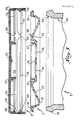
- Fig. 1 est une coupe axiale à échelle agrandie, montrant en superposition, préalablement à leur assemblage, les deux pièces constitutives d'un dispositif d'obturation suivant l'invention et la partie supérieure du récipient correspondant.
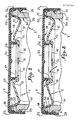
- Fig. 2 reproduit fig. 1 après assemblage des trois éléments au moment du bouchage du récipient.
- Fig. 3 est une coupe analogue à celle de fig. 2, illustrant la déformation de la cape lors du dégazage.
- Fig. 1 is an axial section on an enlarged scale, showing in superposition, prior to their assembly, the two constituent parts of a closure device according to the invention and the upper part of the corresponding container.
- Fig. 2 reproduced fig. 1 after the three elements have been assembled when the container is capped.
- Fig. 3 is a section similar to that of FIG. 2, illustrating the deformation of the cap during degassing.
Le dispositif d'obturation suivant l'invention tel qu'il apparaît en fig. 1 comprend en premier lieu un obturateur 1 à profil circulaire, réalisé en une matière synthétique relativement souple et déformable. Cet obturateur 1 comporte, au voisinage de son bord extérieur, une partie 10 en forme de cuvette annulaire ouverte vers le haut, qui se raccorde d'une part avec un rebord extérieur 11 ouvert en direction du bas, d'autre part avec une cloison annulaire 12 à profil tronconique ouvert en direction du bas. Cette cloison 12 est elle-même réunie par une partie supérieure arquée 13 à un plateau central 14 qui est solidaire d'une lèvre cylindrique 15 tournée axialement vers le haut. On observera que le plateau central 14 présente une série d'ouvertures ménagées entre des bras radiaux 16.The closure device according to the invention as it appears in FIG. 1 comprises firstly a
Le dispositif comprend également une cape 2 en forme de couvercle, établie en une matière synthétique rigide qui n'est susceptible de se déformer élastiquement que moyennant l'application d'un effort relativement important. La jupe cylindrique de cette cape 2 est divisée par une zone annulaire amincie 20 en deux partie superposées. La partie inférieure 21 est destinée à former ceinture déchirable de garantie et elle comporte un bourrelet interne de retenue 22, tandis que la partie supérieure 23 présente elle-même une saillie annulaire interne 24. Le fond supérieur 25 de la cape est établi à un profil très légèrement concave ouvert à l'opposé de la jupe, et il est solidaire dans sa partie centrale d'une lèvre cylindrique axiale 26 tournée vers le bas. Il convient de remarquer que les lévres 15 et 26, destinées à coopérer l'une avec l'autre, comportent une face droite et une face oblique. La face oblique, référencée 17, de la lèvre 15 est disposée à l'interieur alors que la face oblique 27 de la lèvre 26 est située à l'extérieur. De plus, ces deux faces obliques 17 et 27 présentent des angles légèrement différent.The device also comprises a
Le dispositif ainsi agencé est destiné à assurer l'obturation d'un pot en verre 3 dont l'ouverture 30 est bordée à son sommet par un rebord 31 tourné vers l'extérieur.The device thus arranged is intended to close off a
Lors du bouchage réalisé après remlplissage du pot 3 ainsi agencé, l'obturateur 1 est engagé dans l'ouverture 30, la cuvette 10 venant s'adapter étroitement dans le débouché supérieur 32 de ladite ouverture en assurant un contact étanche. Comme illustré en fig. 2, le rebord 11 vient lui-même prendre appui contre la face supérieur plane du rebord 31. Pour opérer le bouchage complet, il suffit de mettre en place la cape 2 ; le bourrelet 22 de la ceinture de garantie 21 vient s'encliqueter au-dessous du rebord 31 en assurant la retenue de ladite cape et de l'obturateur 1 coiffé par celle-ci, étant observé que le bord libre de cet obturateur 1 vient lui-même se clipser au-dessus de la saillie annulaire 24. Par ailleurs, la lèvre 26 de la cape 2 s'engage à force à l'intérieur de la lèvre 15 de l'obturateur qui est ainsi déformée ; on obtient ainsi un contact étanche qui opère en quelque sorte le bouchage du plateau central ajouré 14 de l'obturateur.During the capping carried out after filling the
On peut remarquer que la coopération des lèvres cylindriques 15 et 26 renforce l'application élastique de la cuvette 10 contre le débouché 32 de l'ouverture 30 du pot 3, de telle sorte que l'étanchéité à ce niveau est obtenue même dans le cas où le débouché précité serait mal calibré dans ses dimensions comme dans son profil. En même temps, la déformation qui résulte de la coopération susvisée provoque, outre l'abaissement du plateau central ajouré 14, le raidissement de celui-ci qui se comporte alors comme une paroi pratiquement rigide.It can be noted that the cooperation of the
Si le contenu du pot 3 engendre à un moment donné une surprssion interne, cette dernière contre la partie centrale du fond 25 définie par la lèvre 26, si bien que lorsque l'effet de poussée ainsi exercé dépasse un certain seuil, c'est l'ensemble du fond 25 qui se déforme momentanément vers le haut (fig. 3), ledit fond 25 perdant son profil concave pour affecter un profil pratiquement plan. Cette deformation de la cape 2 fait cesser l'étanchéité du contact des deux lèvres 26 et 15, de telle sorte que les gaz sous pression enclos dans la partie supérieure du pot 3 peuvent s'échapper à l'extérieur en traversant tout d'abord l'espace ménagé entre les deux lèvres précitées, puis des rainures 18, 28 et 29 pratiquées à cet effet respectivement dans la face supérieure du rebord annulaire 11 de l'obturateur 1, dans la saillie annulaire 24 et dans le bourrelet de retenue 22.If the content of the
Il va de soi que cet échappement est instantané et que le fond 25 de la cape 2 revient, de manière pratiquement immédiate sous l'effet de son élasticité, à son profil concave antérieure en assurant à nouveau l'étanchéité au niveau des lèvres 26 et 15. L'échappement est susceptible de se répéter autant de fois que nécessaire pour permettre l'évacuation plus ou moins périodique des gaz engendrés par le produit renfermé par le pot 3. On observera que la déformation momentanée du fond 25 peut intervenir même dans le cas où les pots fermés se trouveraient empilés les uns sur les autres, par suite du profil concave dudit fond et du profil le plus souvent concave du fond des pots de ce type.It goes without saying that this escapement is instantaneous and that the
Bien évidemment, la ceinture de garantie 21, qui n'est au surplus nullement obligatoire, joue le rôle habituel, à savoir qu'elle garantit par sa présence le contenu original du pot 3 jusqu'au moment de la première utilisation de celui-ci. Une fois cette ceinture 21 éliminée par déchirage au niveau de la zone amincie 20, la cape 2 n'est plus retenue sur le pot 3, si bien qu'elle peut être otée par l'utilisateur, étant observé que l'obturateur 1 est enlevé en même temps du fait que le clipsage du bord terminal du rebord 11 au-dessus de la saillie annulaire 24 assure la solidarisation des deux pièces 1 et 2 du dispositif de bouchage.Obviously, the
On conçoit que la mise en place de ce dispositif peut être effectuée en deux phases successives comme on l'a décrit plus haut, ou en une seule phase, les deux pièces 1 et 2 étant alors assemblés l'une à l'autre soit par clipsage au-dessus de la saillie 24, soit par simple engagement du bord de l'obturateur 1 dans le logement annulaire déterminé entre le bourrelet 22 et ladite saillie 24.It is understood that the installation of this device can be carried out in two successive phases as described above, or in a single phase, the two
Claims (8)
Applications Claiming Priority (2)
| Application Number | Priority Date | Filing Date | Title |
|---|---|---|---|
| FR8606725A FR2598387B1 (en) | 1986-05-06 | 1986-05-06 | SEALING DEVICE WITH DEGASSING VENT FOR JARS, VIALS AND SIMILAR CONTAINERS |
| FR8606725 | 1986-05-06 |
Publications (1)
| Publication Number | Publication Date |
|---|---|
| EP0248744A1 true EP0248744A1 (en) | 1987-12-09 |
Family
ID=9335090
Family Applications (1)
| Application Number | Title | Priority Date | Filing Date |
|---|---|---|---|
| EP87420121A Withdrawn EP0248744A1 (en) | 1986-05-06 | 1987-05-06 | Closure device with venting means for jars, bottles and like containers |
Country Status (2)
| Country | Link |
|---|---|
| EP (1) | EP0248744A1 (en) |
| FR (1) | FR2598387B1 (en) |
Cited By (5)
| Publication number | Priority date | Publication date | Assignee | Title |
|---|---|---|---|---|
| WO1995019919A1 (en) * | 1994-01-21 | 1995-07-27 | Colgate-Palmolive Company | Container closure and venting means |
| WO2002024542A3 (en) * | 2000-09-20 | 2002-07-11 | Alcoa Closure Systems Int Inc | Venting plastic closure |
| WO2009111147A1 (en) * | 2008-03-03 | 2009-09-11 | Sonoco Development, Inc. | Resealing overcap for a container |
| US8360256B2 (en) | 2006-04-18 | 2013-01-29 | Packaging Innovation Limited | Storage and drinking container having cap and retaining ring |
| US9051095B2 (en) | 2011-10-12 | 2015-06-09 | Sonoco Development, Inc. | Sealing overcap for a container |
Citations (4)
| Publication number | Priority date | Publication date | Assignee | Title |
|---|---|---|---|---|
| FR608018A (en) * | 1925-12-16 | 1926-07-13 | High vacuum container | |
| US3708083A (en) * | 1970-11-25 | 1973-01-02 | L Kutik | Closure fitment |
| FR2235064A2 (en) * | 1973-06-29 | 1975-01-24 | Beghini Gino | Cover of vacuum sealed container - with to lips to enable easy opening when needed |
| US4192428A (en) * | 1977-08-16 | 1980-03-11 | Segmueller B J | Bottle cap |
-
1986
- 1986-05-06 FR FR8606725A patent/FR2598387B1/en not_active Expired
-
1987
- 1987-05-06 EP EP87420121A patent/EP0248744A1/en not_active Withdrawn
Patent Citations (4)
| Publication number | Priority date | Publication date | Assignee | Title |
|---|---|---|---|---|
| FR608018A (en) * | 1925-12-16 | 1926-07-13 | High vacuum container | |
| US3708083A (en) * | 1970-11-25 | 1973-01-02 | L Kutik | Closure fitment |
| FR2235064A2 (en) * | 1973-06-29 | 1975-01-24 | Beghini Gino | Cover of vacuum sealed container - with to lips to enable easy opening when needed |
| US4192428A (en) * | 1977-08-16 | 1980-03-11 | Segmueller B J | Bottle cap |
Cited By (8)
| Publication number | Priority date | Publication date | Assignee | Title |
|---|---|---|---|---|
| WO1995019919A1 (en) * | 1994-01-21 | 1995-07-27 | Colgate-Palmolive Company | Container closure and venting means |
| US5454489A (en) * | 1994-01-21 | 1995-10-03 | Colgate-Palmolive Company | Pouring member having self sealing venting closure |
| WO2002024542A3 (en) * | 2000-09-20 | 2002-07-11 | Alcoa Closure Systems Int Inc | Venting plastic closure |
| US6769559B2 (en) | 2000-09-20 | 2004-08-03 | Alcoa Closure Systems International | Venting plastic closure |
| US8360256B2 (en) | 2006-04-18 | 2013-01-29 | Packaging Innovation Limited | Storage and drinking container having cap and retaining ring |
| WO2009111147A1 (en) * | 2008-03-03 | 2009-09-11 | Sonoco Development, Inc. | Resealing overcap for a container |
| US7909204B2 (en) | 2008-03-03 | 2011-03-22 | Sonoco Development, Inc. | Resealing overcap for a container |
| US9051095B2 (en) | 2011-10-12 | 2015-06-09 | Sonoco Development, Inc. | Sealing overcap for a container |
Also Published As
| Publication number | Publication date |
|---|---|
| FR2598387A1 (en) | 1987-11-13 |
| FR2598387B1 (en) | 1988-09-02 |
Similar Documents
| Publication | Publication Date | Title |
|---|---|---|
| AU719649B2 (en) | Hinged closure for container | |
| EP0247645B1 (en) | Closure for a container with a pouring opening closed by a membrane fixed by induction or conduction | |
| EP0304972B1 (en) | Closure with a pouring device | |
| BE1006543A3 (en) | Closure device for containers automatic release. | |
| FR2666305A1 (en) | DEVICE FOR STORING SEPARATELY FROM AT LEAST TWO PRODUCTS AND FOR MAKING THEIR MIXTURE AT THE TIME OF USE. | |
| FR2600978A1 (en) | DISPENSING CAP WITH ROTATING CAP FOR PASTA PRODUCTS | |
| WO1990014288A2 (en) | Spout for flasks and similar receptacles, with a piercing element for piercing a lid on receptacle necks | |
| BE1003545A3 (en) | CONTAINER HAVING A PRESSURE RELEASED COVER. | |
| AU5959799A (en) | Pierce and cut closure | |
| FR2495111A1 (en) | SEALED CLOSURE COVER FOR CONTAINER | |
| FR2502591A1 (en) | CONNECTION ASSEMBLY FOR TWO-COMPONENT SYSTEMS | |
| US20070029353A1 (en) | Device for holding liquid | |
| EP1794065A1 (en) | Sealing closure device for a container | |
| EP0248744A1 (en) | Closure device with venting means for jars, bottles and like containers | |
| CH637744A5 (en) | SAFETY VALVE FOR PACKAGING. | |
| EP0953513B1 (en) | Metallic package with security cap | |
| FR2693987A1 (en) | Self-perforating hermetic closure device for bottles and similar containers. | |
| CA2477920A1 (en) | Salad shaker | |
| JPH0741028A (en) | Lid of container | |
| GB2305655A (en) | Device or closure for cutting a container seal membrane | |
| EP0283629B1 (en) | Packaging for extemporaneous preparations | |
| EP0659147A1 (en) | Goblet device for fitting to a drinks container | |
| FR2514330A1 (en) | Stopper-pourer for petrol can - uses screw cap to fix supple membrane locating extractable swivel tap under tear off cover | |
| FR2811638A1 (en) | Container tamper protection comprises collar with groove in rim into which lid is clipped, collar has divisible portion which when removed gives access to container peripheral portion | |
| FR2471329A1 (en) | Child-resistant screw cap closure - with external levers which must be operated while unscrewing the closure |
Legal Events
| Date | Code | Title | Description |
|---|---|---|---|
| PUAI | Public reference made under article 153(3) epc to a published international application that has entered the european phase |
Free format text: ORIGINAL CODE: 0009012 |
|
| AK | Designated contracting states |
Kind code of ref document: A1 Designated state(s): AT BE CH DE ES GB GR IT LI LU NL SE |
|
| 17P | Request for examination filed |
Effective date: 19880606 |
|
| STAA | Information on the status of an ep patent application or granted ep patent |
Free format text: STATUS: THE APPLICATION IS DEEMED TO BE WITHDRAWN |
|
| 18D | Application deemed to be withdrawn |
Effective date: 19891201 |
|
| RIN1 | Information on inventor provided before grant (corrected) |
Inventor name: PERNE, RAYMOND Inventor name: ACATI, JEAN-PHILIPPE Inventor name: ODET, PHILIPPE |