EP0247796A1 - Solid phase immunoassay method - Google Patents
Solid phase immunoassay method Download PDFInfo
- Publication number
- EP0247796A1 EP0247796A1 EP87304526A EP87304526A EP0247796A1 EP 0247796 A1 EP0247796 A1 EP 0247796A1 EP 87304526 A EP87304526 A EP 87304526A EP 87304526 A EP87304526 A EP 87304526A EP 0247796 A1 EP0247796 A1 EP 0247796A1
- Authority
- EP
- European Patent Office
- Prior art keywords
- signal
- reagent
- assay
- assay medium
- reaction
- Prior art date
- Legal status (The legal status is an assumption and is not a legal conclusion. Google has not performed a legal analysis and makes no representation as to the accuracy of the status listed.)
- Withdrawn
Links
Images


Classifications
-
- G—PHYSICS
- G01—MEASURING; TESTING
- G01N—INVESTIGATING OR ANALYSING MATERIALS BY DETERMINING THEIR CHEMICAL OR PHYSICAL PROPERTIES
- G01N33/00—Investigating or analysing materials by specific methods not covered by groups G01N1/00 - G01N31/00
- G01N33/48—Biological material, e.g. blood, urine; Haemocytometers
- G01N33/50—Chemical analysis of biological material, e.g. blood, urine; Testing involving biospecific ligand binding methods; Immunological testing
- G01N33/58—Chemical analysis of biological material, e.g. blood, urine; Testing involving biospecific ligand binding methods; Immunological testing involving labelled substances
- G01N33/582—Chemical analysis of biological material, e.g. blood, urine; Testing involving biospecific ligand binding methods; Immunological testing involving labelled substances with fluorescent label
-
- G—PHYSICS
- G01—MEASURING; TESTING
- G01N—INVESTIGATING OR ANALYSING MATERIALS BY DETERMINING THEIR CHEMICAL OR PHYSICAL PROPERTIES
- G01N33/00—Investigating or analysing materials by specific methods not covered by groups G01N1/00 - G01N31/00
- G01N33/48—Biological material, e.g. blood, urine; Haemocytometers
- G01N33/50—Chemical analysis of biological material, e.g. blood, urine; Testing involving biospecific ligand binding methods; Immunological testing
- G01N33/53—Immunoassay; Biospecific binding assay; Materials therefor
- G01N33/543—Immunoassay; Biospecific binding assay; Materials therefor with an insoluble carrier for immobilising immunochemicals
- G01N33/54313—Immunoassay; Biospecific binding assay; Materials therefor with an insoluble carrier for immobilising immunochemicals the carrier being characterised by its particulate form
- G01N33/54326—Magnetic particles
-
- G—PHYSICS
- G01—MEASURING; TESTING
- G01N—INVESTIGATING OR ANALYSING MATERIALS BY DETERMINING THEIR CHEMICAL OR PHYSICAL PROPERTIES
- G01N35/00—Automatic analysis not limited to methods or materials provided for in any single one of groups G01N1/00 - G01N33/00; Handling materials therefor
- G01N2035/00465—Separating and mixing arrangements
- G01N2035/00534—Mixing by a special element, e.g. stirrer
-
- G—PHYSICS
- G01—MEASURING; TESTING
- G01N—INVESTIGATING OR ANALYSING MATERIALS BY DETERMINING THEIR CHEMICAL OR PHYSICAL PROPERTIES
- G01N35/00—Automatic analysis not limited to methods or materials provided for in any single one of groups G01N1/00 - G01N33/00; Handling materials therefor
- G01N35/10—Devices for transferring samples or any liquids to, in, or from, the analysis apparatus, e.g. suction devices, injection devices
- G01N35/1009—Characterised by arrangements for controlling the aspiration or dispense of liquids
- G01N2035/1025—Fluid level sensing
-
- G—PHYSICS
- G01—MEASURING; TESTING
- G01N—INVESTIGATING OR ANALYSING MATERIALS BY DETERMINING THEIR CHEMICAL OR PHYSICAL PROPERTIES
- G01N35/00—Automatic analysis not limited to methods or materials provided for in any single one of groups G01N1/00 - G01N33/00; Handling materials therefor
- G01N35/0098—Automatic analysis not limited to methods or materials provided for in any single one of groups G01N1/00 - G01N33/00; Handling materials therefor involving analyte bound to insoluble magnetic carrier, e.g. using magnetic separation
Definitions
- the present invention relates to assays utilising specific binding, such as immunoassays.
- Solid phase, e.g. particle-based, immunoassay systems are already known. These involve the qualitative and/or quantitative determination of an immunogenic species in a test sample by means of an immunological binding reaction between the immunogenic species (analyte) and one or more specific binding partners therefor, at least one of which binding partners is linked to an insoluble carrier material in contact with a liquid medium comprising the test sample.
- the fact that the resulting immunological complex is linked to the carrier material can be used to advantage during the subsequent determination of the extent to which the binding reaction has taken place.
- the determination is usually achieved by the use of a labelled specific binding partner, and the binding reaction can be either a "competition” reaction or a "sandwich” reaction, both of which are now widely used in this art.
- the assay medium which is generally aqueous, is contacted with the solid phase carrier on which is immobilised a specific binding reagent (e.g. monclonal antibody) having specificity for the analyte to be determined, and the assay medium contains a known quantity of the analyte (or an analogue thereof possessing the identical epitopes) bearing a label and a known quantity of a sample suspected of containing the analyte.
- the labelled analyte or analogue binds with the specific binding reagent immobilised on the solid phase carrier and the extent of this binding is determined from standard experiments.
- the sample contains the analyte
- this competes with the labelled analyte or analogue for the specific binding reagent and hence the extent to which the specific binding reagent becomes coupled to the labelled component is reduced.
- a measure of the analyte concentration in the sample can be derived.
- a first binding reagent having specificity for the analyte is immobilised on the solid phase carrier, and the assay medium, which is again generally aqueous, also contains a second binding reagent having specificity the analyte and which bears a label.
- the assay medium which is again generally aqueous, also contains a second binding reagent having specificity the analyte and which bears a label.
- no coupling can occur between the immobilised reagent and the labelled reagent.
- the analyte acts as a bridge between the immobilised and labelled specific binding reagents and results in indirect coupling of the labelled reagent to the solid phase. The extent of this coupling provides a measure of the analyte concentration in the sample.
- the specificities of the immobilised reagent and the labelled reagent for the analyte can be different, but, if the analyte molecule possesses more than one identical epitopes, it is possible to use the same specific binding reagent both in the immobilised form and in the free-labelled form.
- the present invention seeks to provide a non-separation particle-based immunoassay systems in which the determination of the species under test can be made rapidly and simply, and especially immunoassays wherein only one step is required.
- EP 0169434 describes a fluorometric immunological assay method in which an antigen is attached to magnetic particles which are, for the time of measurement, pulled against the wall of a measurement vessel by means of a magnetic field. To obtain an analytical result in such a system, it is, of course, necessary to stimulate the fluorescence by the external application of energy such UV light.
- EP 0149565 describe immunoassays performed using a labelled reagent and another reagent bound to magnetically attractable particles, which are suspendable but insoluble in a liquid assay medium. After the labelled reagent has become partitioned between the liquid phase and the particles, in proportions which depend on the concentration of an analyte in a sample, the liquid phase is removed. Then the particles are resuspended in another liquid medium and the concentration of label observed.
- the method is said to be particularly suitable for fluorescent and chemiluminescent label systems, and can conveniently be performed in microtiter plates in which the wells are optically screened from one another, the observation being made from above or below the wells.
- EP 0149565 specifically states that it is difficult to make useful measurements of any optical signal generated from the pellet which results from bringing down a particulate reagent out of suspension.
- the invention provides a carrier-based assay method which utilises a specific binding partner which is labelled such that the label continuously generates a signal in the test medium, and in which method, following the binding reaction, the carrier material is moved to an environment within the assay medium wherein any enhanced local signal flux can be detected.
- the invention provides an assay method for determining qualitatively and/or quantitatively the presence of an analyte in a sample by means of specific binding, wherein the sample is contacted with a moveable solid phase carrier material on which is immobilised a first binding reagent having specificity for the analyte and with a labelled specific binding reagent which can participate in either a "sandwich” or a "competition” reaction with the first reagent in the presence of the analyte, and in which method, following an incubation period sufficient to allow the reaction to take place, the moveable solid phase carrier material is moved within the assay medium to a location adjacent a signal sensing means, the label generating a signal continuously in the assay medium and the magnitude of the signal generated in the vicinity of the sensing means being used as a measure of the extent to which the binding reaction has occurred.
- the invention provides, as one embodiment, a particle-based immunoassay method which utilises a specific binding reagent which is labelled such that the label continuously generates a signal in the assay medium, which signal is suppressed while the labelled binding reagent is uniformly dispersed in the assay medium, and in which method, following the binding reaction, the particulate carrier material is localised in an environment having insufficient signal-suppressing, ability to overcome the locally-generated signal, and hence a detectable signal can be generated the nature and/or magnitude of which is dependent on the extent of binding that has taken place between the analyte and the specific binding reagent carried by the particles.
- the invention provides a particle-based immunoassay method which utilises a specific binding partner which is labelled such that the label continuously generates a signal in the test medium, which signal is masked or quenched or otherwise suppressed while the labelled binding partner is uniformly dispersed within the test medium, and in which method, following the binding reaction, a local concentration of the particulate carrier material is established in the test medium such that the local concentration of complexed labelled binding partner carried by the particles provides a local signal flux that is sufficient to overcome the local signal-suppressing ability of the test medium and hence to provide a detectable signal the nature and/or magnitude of which is dependent on the extent of binding that has taken place between the immunogenic species under test and the specific binding partner carried by the particles.
- the term "signal” is used to denote any phenomenon that can be observed or measured, qualitatively or quantitatively, and the term “detectable signal” is used to denote any significant change in the signal that can be observed or measured.
- the signal can be the concentration of a chemical entity
- the detectable signal can be an increase or decrease in concentration from a relatively uniform "background” signal (which might be zero).
- Another example of a detectable signal would be a change in the rate of accumulation of a chemical entity.
- a further example of a detectable signal would be change in the intensity of electromagnetic radiation, such as visible light, emitted by a chemical species such as a chemiluminescent agent.
- the solid phase e.g. the particulate carrier
- the solid phase initially has access to the bulk of the test medium, and hence can be under the influence of any signal-suppressing activity that the bulk medium possesses. Subsequently, the solid phase is placed in a situation wherein it has relative freedom from the bulk sample and hence is less influenced by the signal-suppressing effect.
- the movement of the solid phase is the only action that needs to be performed in order to give a readable result.
- Constant signal production by the label itself obviates the need to add further reagents or to provide further stimuli after particle localisation has taken place and provides maximum sensitivity of detection with the minimum complexity or number of operations.
- the simple act of physically localising the carrier particles is all that is required in order for a detectable signal to be produced.
- the suppression of the signal generated by the labelled binding partner when dispersed in the test medium is a most important feature of the invention.
- the mechanism by which the signal is suppressed will depend on the nature of the signal generating system itself. The following mechanisms, which are given by way of example only, illustrate the range of possibilities that exist.
- the signal suppressing effect in the bulk sample must be balanced such that a local concentration of the label produces a detectable signal. In any given system, the level of suppression has to be determined by experiment and experience. However, this is not difficult to achieve.
- a dispersed mixture of the carrier material, bound signal generator and free signal generator, representing the concentration that would be expected in the non-localised sample is, "titrated" with the appropriate signal suppressing means (e.g. a consumer reagent) until the level of signal suppression is just sufficient to ensure that there is no net production of signal in the absence of localisation of the bound signal generator.
- the label can be a chemical agent that reacts with a substrate present in the medium to produce a chemical product. If the test medium contains in appropriate concentration a consumer reagent that destroys all or most of the chemical product as soon as it is formed, a uniform background signal (e.g. the absolute concentration or rate of change of concentration of the chemical product) will be maintained as long as the label remains dispersed throughout the bulk of the test medium. However, following a binding reaction with a specific binding partner linked to the carrier particles, localisation of the particles within a zone in the test medium can cause the chemical product to accumulate at a rate which significantly exceeds the rate at which the consumer reagent can destroy the chemical product in that zone. The increasing quantity of chemical product in the immediate vicinity of the localised particles will constitute a detectable signal.
- a uniform background signal e.g. the absolute concentration or rate of change of concentration of the chemical product
- the consumer reagent While the particulate carrier material is localised within a zone in the test medium, the consumer reagent must remain uniformly dispersed throughout the bulk of the test medium.
- Such a chemical suppression can be achieved easily using, for example, glucose oxidase enzyme as the label, glucose as the substrate in the test medium, and catalase enzyme in the test medium as the consumer reagent.
- concentration of catalase in the test medium can be chosen such that under normal circumstances, while the glucose oxidase is uniformly dispersed in the test medium, all or most of the hydrogen peroxide produced by reaction between the glucose oxidase and the glucose is immediately destroyed by the catalase.
- the background level of hydrogen peroxide will remain constant or will alter only slowly and uniformly.
- the particulate carrier bearing a complex including the glucose oxidase-labelled specific binding partner is concentrated in a comparatively small zone in the test medium, the amount of hydrogen peroxide accumulated in that locality will be sufficient to overcome the action of the catalase, and can be measured as an increased rate of accumulation of the peroxide.
- the hydrogen peroxide can be detected, for example, by using an appropriate electrode, the localisation of the particulate carrier being effected in the immediate vicinity of the electrode.
- Interfering chemicals which can be present in the sample, such as ascorbic acid or paracetamol, and which can give rise to spurious electrochemical signals like that caused by peroxide, can be consumed by means of an electrode in the cell. This may avoid the need for selective membranes protecting the working electrode.
- the chemical product "signal" can be detected via a further chemical reaction with another reagent which is localised on or in a surface.
- the particulate carrier material to which the complex is linked can be localised adjacent a surface (such as a slab, sheet, film or membrane, or a second particulate carrier material) containing or carrying a reagent which interacts with the "signal" product and which results in, for example, the formation of a colour change in or on the surface or the emission of light from the surface.
- the detector surface could contain or carry a peroxide-utilising enzyme, such as horseradish peroxidase (HRP), leading to the formation of a coloured product by oxidation of a substrate in or on the detector surface.
- a peroxide-utilising enzyme such as horseradish peroxidase (HRP)
- Another alternative can be the use of a label that alters the pH of the test medium, such as urease or penicillinase, with an appropriate substrate (such as urea) in the test medium.
- a label that alters the pH of the test medium such as urease or penicillinase
- an appropriate substrate such as urea
- the effect of the label can be masked or quenched by incorporating a pH buffer in the test medium.
- the local concentration of label will cause a pH change that overcomes the buffering capacity of the test medium in the immediate vicinity of the localised carrier particles.
- This pH change can be detected, for example, using a pH electrode or a pH-responsive indicator paper.
- the sensing means comprises a gas detector located outside the vessel in which the assay is conducted.
- the sensor can, for example, be a chemical field effect transistor (Chemfet), sensing ammonia.
- the sensor can be located adjacent a gas-permeable membrane in the vessel wall, against which the carrier material is localised.
- the label can be urease enzyme, converting substrate urea to ammonia, and the test medium can contain l-glutamate dehydrogenase as a consumer reagent.
- a system that is completely different in detail but analogous in principle, can be made using a label which is chemiluminescent or which participates in a chemiluminescent reaction with other components of the test medium. If the test medium is opaque or at least insufficiently translucent for the light to be observable when the labelled specific binding partner is evenly dispersed in the test medium, an optical signal will not be detectable.
- the test medium can contain a chemical species that interacts with a component of the light-generating system, and quenches or inhibits the production of an optical signal. Subsequent localisation of the particulate carrier to which is linked a complex involving the labelled specific binding partner can give rise to a localised optical signal which is of sufficient intensity to be detectable.
- the localisation can be effected, for example, adjacent a "window" in the vessel holding the test medium, or adjacent an optical sensor.
- the placing of a (second) optical sensor in the body of the test fluid to measure the background light intensity would be useful in providing means for calibration or normalisation.
- Such a system can be provided using, for example, horseradish peroxidase as the label, with luminol and a peroxide (such as H2O2) in the medium.
- the medium can contain a dye, sufficiently chemically inert not to be affected by the peroxide reaction, which gives the medium an optical density at an appropriate wavelength that is sufficiently high (preferably O.D. of at least about 2) to render the light generated by the dispersed label insignificant in comparison with that observable from a localised concentration of the label.
- dyes attenuators
- the test medium can contain a chemical reagent that interferes with the generation of the luminescence.
- a further way in which the chemiluminescent signal can be reduced or eliminated in the bulk test sample is to include a quencher reagent in the sample.
- a quencher reagent for example, if horseradish peroxide enzyme is used as the label, reacting with peroxide and luminol in solution to produce visible light, the reaction can be inhibited by incorporating a competing reagent, such as gallic acid or thiodiglycollic acid, in the sample.
- a fluorescer system that can absorb the chemiluminescent light and emit at a different wavelength.
- a fluorescer system can help to screen out the effect of light generated in the bulk sample, especially if the emitted light is viewed through an appropriate filter.
- blue light from luminol can be absorbed by a coumarin, which will emit yellow/green light.
- the fluorescer can be located on or near the signal sensing means.
- the fluorescer can be used as a marking agent dispersed in the bulk sample, so that only a localised generation of chemiluminescence is observable.
- luminol (5-amino-2,3-dihydro-1,4-phthalazinedione) is a particularly preferred chemiluminescent agent for use in the context of the invention
- chemiluminescent agent for use in the context of the invention
- other derivatives of 2,3-dihydro-1,4-phthalazinedione, such as the 6-amino derivative (isoluminol) can be used.
- Other examples are luciferin and acridinium esters.
- Such systems are generally described, for example, in GB 1552607, GB 2112779A and GB 2095830B.
- chemiluminescent reactions tend to be short-lived, which may lead to time constraints on the assay procedure.
- An important embodiment of the invention is a particle-based assay method which utilises a specific binding partner which is labelled with a reagent that participates in a chemiluminescent reaction, the other essential reagent(s) for the chemiluminescent reaction being present in abundance in the test medium, such that the chemiluminescent reaction takes place continuously in the test medium, the light so produced being masked or quenched while the labelled binding partner is uniformly dispersed within the test medium, and in which method following the binding reaction a local concentration of the particulate carrier material is established in the test medium adjacent a detection means such that the local concentration of complexed labelled binding partner carried by the particles provides a local emission of light which is sufficient to overcome the local masking or quenching ability of the test medium and hence to provide a detectable signal, the nature and or magnitude of which is dependent on the extent of binding that has taken place between the species under test and the specific binding partner carried by the particles.
- a further embodiment of the invention is a particle-based assay method which utilises:
- the label can be, for example, glucose oxidase reacting with glucose and oxygen in the test medium to produce hydrogen peroxide as the precursor
- the consumer can be catalase enzyme
- the bound reagent can be horseradish peroxidase interacting with luminol in the text medium. If desired, the bound reagent can be carried on the surface or entrapped within the particles of the second population.
- Sequential addition of the components in the test medium can be advantageous, e.g. to permit adequate time ("incubation") for the immunological binding reaction(s) to take place prior to the addition of a substrate required for the generation of a signal by the label. It will thus be appreciated that the continuous generation of signal by the label will only take place when the necessary substrates have been added. This addition will always be made before the solid phase is relocated to the detection zone or environment. The continuity of the signal generation must last at least for the duration of the time taken to localise the solid phase and to detect the signal produced therefrom.
- the incubation period needed for the specific binding reaction(s) to take place will depend on many factors, such as the nature of the reagents and the analyte, their relative and absolute concentrations, and on physical factors such as temperature. These parameters are familiar to thos skilled in this art. In general, the incubation period will not exceed about an hour, and for most applications will lie in the range 30 minutes to one hour.
- Localisation of the carrier material can be achieved in a wide variety of ways.
- One simple embodiment is to allow particles to settle under gravity, although this necessitates a uniform suspension of the particles in the test medium being maintained, eg. by stirring, while the binding reaction is taking place. Centrifugation can be used as an alternative to gravitation. Alternatively, particles can be localised by passing a porous membrane or filter through the bulk of the test medium, thus sweeping the particles into a small volume. Another alternative is to use a particulate carrier material which, under the influence of magnetism or another externally-applied force, can be urged into a particular locality within the bulk of the test medium. The particles can be moved through a test medium by the ultrasonic generation of a drifting standing wave.
- the solid phase can be made of any suitable carrier material.
- magnetic i.e. particles that can be induced to move through a liquid under the influence of a magnetic field
- particles of a variety of suitable sizes ranging for example from less than about 1 to more than about 300 ⁇ , are available commercially.
- particle sizes ranging for example from less than about 1 to more than about 300 ⁇ , are available commercially.
- particle sizes ranging for example from less than about 1 to more than about 300 ⁇ , are available commercially.
- particle sizes of at least about 50 ⁇ , and not greater than about 300 ⁇ are preferred, depending on the density of the material.
- Commercially-available oxirane acrylic beads are very suitable, especially for assays involving labelled haptens.
- Techniques for sensitising and/or coupling such solid phase carriers to binding reagents, such as immunoglobulins are well known standard techniques in the art, and form no part of the present invention.
- Steroid hormones such as those involved during pregnancy or which are influential on fertility, e.g. progesterone and oestrogens.
- Urinary metabolites such as oestrone-3-glucuronide and pregnanediol-3-glucuronide.
- Peptide hormones such as human chorionic gonadotrophin, luteinising hormone and follicle stimulating hormone.
- Proteins such as urinary albumin, beta-2 microglobulins and retinol binding protein. High and low-density lipoprotein, the detection of which is valuable in cardiovascular monitoring, and cardiac troponin.
- Infectious disease markers such as Rubella antibodies and Toxoplasma antibodies.
- Immunoglobulins such as monoclonal antibodies.
- test medium can thus be derived from many sources, especially body fluids such as urine, serum and plasma.
- the invention is especially applicable to the screening of the cell culture media for immunoglobulins, e.g. in the production of monoclonal antibodies.
- the specific binding partners can be polyclonal or monoclonal antibodies or antigens, lectins, or hormones and their receptors. Such materials are well known in the art, many are available commercially, and their precise nature forms no part of the present invention.
- the sample suspected of containing the analyte is of variable nature, (e.g. serum and urine) or contains components which could interfere with the specific binding reactions or with the production of the observable signal, it can be advantageous to dilute the sample, e.g. with water or a buffer solution, before an assay method of the invention is applied, to reduce the likelihood of such interference.
- An assay test kit in accordance with the invention can comprise, for example, a re-usable cell or plurality of such cells, complete with the signal sensing means (e.g. electrodes), or a disposable cell or cells incorporating a membrane through which the signal can pass to a re-usable sensing means, or a wholly disposable cell and signal sensing means combination.
- the signal sensing means e.g. electrodes
- a disposable cell or cells incorporating a membrane through which the signal can pass to a re-usable sensing means or a wholly disposable cell and signal sensing means combination.
- Appropriate reagents e.g. the solid phase and other essential components, can also be supplied as necessary.
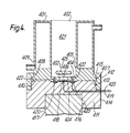
- the apparatus comprises a cell 101 [depicted as being rectangular although in practice the shape will be immaterial] containing a volume 102 of liquid test medium.
- a cell 101 [depicted as being rectangular although in practice the shape will be immaterial] containing a volume 102 of liquid test medium.
- a platinum foil electrode 104 mounted on the inner face of one wall 103 of cell 101.
- Electrode 104 is linked via a connector 105 to a polarographic analyser [not shown] situated outside cell 101.
- Dipping into the text medium 102 from the open top 106 of cell 101 is a platinum counter electrode 107 and a silver/silver chloride reference electrode 108.
- a stirrer 109 is also provided to assist dispersion of material within the cell.
- a moveable bar magnet 110 can be placed at will outside the cell 100 immediately adjacent to the electrode 104.
- the platinum foil electrode 104 can be set at voltage of plus 0.7 volts and is thereby capable of detecting the presence of hydrogen peroxide.
- the binding reaction can be conducted while the particles are dispersed uniformly in the test medium. Thereafter, by introducing the magnet 110, the magnetic particles can be localised in the immediate vicinity of the detection electrode 104.
- Magnetic particles prepared as described by Pourfarzaneh et al (Methods of Biochemical Analysis, 1982 28 , 267-295), were oxidised with periodic acid to generate surface aldehyde groups to which commercially available avidin was linked. This was achieved by treating 500mg of washed particles in 12.5ml distilled water with 400mg sodium periodate in 5ml of distilled water. The treatment was continued for one hour at room temperature in the dark, with end-over-end mixing. Excess periodate solution was removed and the oxidised particles then washed twice with distilled water and 3 times with borate buffer, pH 9.0, before the addition of 25ml of avidin solution (2mg/ml) in borate buffer (pH 9.0).
- Biotinylated glucose oxidase was obtained commercially as a freeze dried powder and contained approximately 20nmols biotin per mg protein. It was reconstituted as recommended and diluted in PBST immediately before use.
- bovine liver catalase was obtained as a purified powder. Working solutions in PBS were prepared freshly each day.
- d-biotin was obtained commercially as a crystalline solid, and solutions of appropriate concentration were prepared by dilution from a reference solution consisting of an accurately weighed quantity of biotin dissolved in PBS.
- the particles, conjugate and sample were suspended in PBS containing glucose at 1.0mg/ml and catalase at 2.5 ⁇ g (approximately 25 units/ml). All of the solutions and reactants were free of sodium azide.
- Solutions of biotin-glucose oxidase conjugate were prepared by diluting 100 ⁇ l of reconstituted stock solution in 10ml of PBST alone (to give the maximum conjugate-binding signal) or 10ml PBST containing 100 ⁇ g of free biotin (to give the absolute minimum, fully inhibited signal).
- 100 ⁇ l of stock suspension of avidin-magnetic particles was added and, after a minimum of 10 minutes (to allow binding) the resultant mixtures were placed in the electrochemical cell with 3.8ml of reaction medium.
- the polargraphic analyser and recorder were switched-on, to monitor the quantity of H2O2 reaching the electrode.
- the magnet was applied and the particles collected by magnetic attraction onto the surface of the electrode. The particles could be released into suspension again by removing the magnet and agitating the solution.
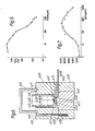
- Line A in Figure 2 illustrates the typical trace obtained from the polarographic analyser.
- the response rose rapidly by about 0.4 ⁇ A, indicating a significant build-up of peroxide in the vicinity of the electrode.
- the magnet was removed and the particles became dispersed quite rapidly back into the volume of the test medium.
- the response therefore fell to a background level 203 which was rising at a uniform slow rate associated with the gradual build-up of peroxide in the volume of the test medium which was not completely destroyed by the catalase.
- the magnet was reintroduced, and an identical response obtained up to point 205, after which the magnet was again removed.
- the response thereafter returned to the background level, which had risen only slightly from the previous background.
- This coated wire was glued with polystyrene cement to a top corner of the cell.
- the particles could be attracted on to the electrode by placing a pole of the magnet onto the outside of the corner. The particles then clustered around the electrode.
- This example illustrates particle localisation by gravitation.
- the apparatus used was a slightly modified Rank Oxygen Electrode and is depicted in cross-sectional elevation in Figure 4.
- This comprised an upright cylindrical water-jacketed sleeve 401 fully opened at the top end 402 and partially opened at the bottom end 403.
- the bottom end 403 is partially closed by an annular extension 404 of the inner face 405 of the sleeve, leaving a central circular orifice 406.
- the sleeve 401 has an external flange 407 running around the bottom end 408 of the outer wall 409 and the sleeve fits flushly on to the top surface 410 of a cylindrical base 411.
- the sleeve 401 and base 411 can be secured together by means of an outer ring 412, which is threaded internally to engage with a correspondingly threaded region 413 on the outside 414 of the base 411 and which has an internal annular lip 415 that fits over the flange 407 on the sleeve.
- the lower region of base 411 is centrally recessed 415 to accommodate a magnetic stirrer drive 417.
- a platinum button electrode 418 which in the assembled apparatus, lies in the central orifice 406 in the partially-closed bottom end 403 of sleeve 401.
- An electrical connector 419 passes from the electrode 418 through the base 411 to a polarographic analyser (not shown).
- a silver ring electrode 420 is mounted on base 411 concentrically with the platinum electrode 418 but spaced therefrom. In the assembled apparatus, the ring electrode 420 lies beneath the annular extension 404.
- a plurality of holes 422 were made in the annular extension 404 two of which are seen in Figure 3.
- a second electrical connector 423 passes from ring electrode 420 through base 411.
- a membrane 424 (made from standard laboratory dialysis membrane) is clamped between sleeve 401 and base 411 covering both electrodes.
- the bar 425 of a magnetic stirrer lies in the cell 421 within the sleeve, and can be actuated by the stirrer head 417.
- the solid phase was avidin from egg-white attached to commercially available epoxy-activated agarose (10 to 180 microns diameter) and containing 1-2 ⁇ 106/ml particles with the capacity of binding 20 ⁇ g of biotin per ml.
- the assay medium was prepared from the avidin-agarose (50 ⁇ l of gel) in 1ml of phosphate buffered saline (PBS) containing the conjugate and biotin solution, and incubated at room temperature. For each experiment a 25 ⁇ l aliquot of the pre-incubated gel/conjugate/biotin solution was added to 2.5ml of PBS containing 5mg/ml glucose and 10 ⁇ g of catalase. This was equivalent to 10 ⁇ l of gel and 1.25 of glucose oxidase in total. Stirring was continued while a base line H2O2 concentration was established, and the localised signal was measured after removing the magnetic stirrer bar with the aid of a hand-held magnet. The magnetic bar was replaced to stir the particles again to redistribute the components. Whenever the magnetic bar was removed, the particles sedimented very rapidly on to the membrane covering the electrodes.
- PBS phosphate buffered saline
- the magnetic stirrer bar was removed from the cell and the particulate carrier material immediately settled under gravity. Hydrogen peroxide immediately began to accumulate in the immediate vicinity of the platinum electrode and the response rose rapidly.
- the stirrer bar was reintroduced into the cell and the particulate material dispersed. The response thereafter fell rapidly to the original base line 304. The following cycles show that this effect was fully reproducable as the stirrer bar was successively removed and reintroduced.
- This example demonstrates the determination of oestrone-3-glucuronide (E3G) as analyte.
- the equipment used was the same as that described under Example 3 above, except that a mechanical top-driven stirrer was used in place of the magnetic stirrer; and the electrode system comprised a single flat disc platinum working electrode covering the entire bottom surface of the cell, plus a platinum counter electrode and a silver/silver chloride reference electrode both dipped into the cell from the top.
- Oxirane acrylic beads (epoxy-activated) were obtained commercially and were coupled to the IgG fraction of a rabbit anti-mouse serum.
- the antibody- linked beads were stored in phosphate buffered saline (PBS) pH 7.1.
- E3G was chemically attached to glucose oxidase by a modification of the SPDP method, in which the carboxyl group of the glucuronide was activated by reaction with a pyridyl thioamine derivative and a water soluble carbodiimide.
- the resultant conjugate was able to bind to monoclonal antibodies to E3G and had retained most of its glucose oxidase activity. It was stored as a solution in PBS at +4°C, and aliquots were diluted to working strength as necessary each day.
- Mouse monoclonal antibodies with specificity for free E3G were prepared by conventional means with E3G/BSA conjugates as the immunogen.
- the hybridoma cells were grown in serum-free culture medium and the monoclonal antibodies were isolated by ion-exchange chromatography.
- bovine liver catalase was obtained as a purified powder. Working solutions in PBS were prepared freshly each day.
- This example illustrates the generation of a detectable hydrogen peroxide signal by localisation of a particulate carrier onto a gel layer in which the peroxide can be detected by means of a chemical reaction resulting in the emission of visible light from the gel. While the carrier material remains dispersed in the sample, free catalase enzyme is used to destroy the peroxide and eliminate any signal from the bulk sample.
- a set of small closable transparent plastics sample tubes are used as the basic assay cells.
- the exact size is not important, but usually these are about 1cm in diameter and about 3cm in height.
- a small quantity (e.g. 0.15ml) of agarose detector gel is cast into the base of each tube.
- Biotinylated glucose oxidase obtained commercially as a freeze dried powder and containing approximately 20nmols biotin per mg protein. It is reconstituted as recommended and diluted in PBST immediately before use.
- d-biotin obtained commercially as a crystalline solid, and solutions of appropriate concentration prepared by dilution from a reference solution consisting of an accurately weighed quantity of biotin dissolved in PBS.
- the biotin concentration is varied, e.g. from 5ng/ml to 100 ng/ml.
- the encapsulated HRP can be obtained commercially and consists of enzyme entrapped in polyamide micro capsules (20-80 ⁇ diameter) at a level of 0.656 units per mg of wet solids.
- the capsule membranes are semi-permeable, allowing free diffusion of small molecules such as hydrogen peroxide but retaining molecules of molecular weight greater than 10,000.
- a sample of the avidin-sensitised beads is centrifuged and the supernatant removed.
- a 0.05% solution of keltrol in buffer solution is added to produce a 50/50 suspension of beads.
- a 5 ⁇ g per ml solution of glucose oxidase biotin conjugate from the stock reagent is prepared in 0.05% keltrol in buffer.
- To each of a number of microfuge tubes is added 100 ⁇ l of the bead suspension, 500 ⁇ l of the conjugate and 500 ⁇ 1 of biotin solution. Each tube is capped and placed on an end-over-end mixer for 2 hours at ambient temperature.
- This example illustrates the generation of a chemiluminescent signal and the use of the localisation of a particulate carrier material in the assaying of a monoclonal antibody.
- This procedure can be used in the screening of cell culture media, e.g. for the presence of immunoglobulins such as monoclonal antibodies.
- the beads were washed in the same buffer (2 ⁇ 5ml) and then washed in PBS (2 ⁇ 5ml) and stored in a known volume of PBS containing 0.1% BSA + 0.01% Thimerosal preservative at 4°C.
- the contents of the tube were thoroughly mixed and the magnetic solid phase was then localised at the base of the tube by placing a permanent magnet adjacent the underside of the tube for five minutes. The tube was then removed from the magnet and placed carefully (so as not to dislodge the pellet of localised particles) into a light sensor.
- the device comprises an upright open-topped cylindrical housing 600 accommodating within it a photomultiplier tube 601.
- the window 602 of photomultiplier tube 601 lies flush with the top 603 of housing 600 and is directed vertically upwards.
- the constructional details of the photomultiplier tube 601 are not shown, as these are irrelevant to the invention.
- a flat circular plate 604 of the same diameter as housing 600 is superimposed on the top 603 of housing 600.
- Plate 604 is pierced centrally by a small circular aperture 605 directly above window 602 of photomultiplier tube 601.
- the lower surface 606 of plate 604 incorporates a horizontal slot which leaves a narrow gap 607 between plate 604 and the top 603 of cylindrical housing 600, into which gap a horizontally slidable shutter 608 can be moved.
- Shutter 608 communicates with the outside of the device and hence can be opened and closed manually.
- Shutter 608 is depicted in the open position. When fully inserted, shutter 608 blocks aperture 605 and effectively prevents any light reaching window 602 of photomultiplier tube 601.
- annular body 609 Superimposed on plate 604 is an annular body 609 of the same external diameter as housing 600 and plate 604, and having its vertical cylindrical axis on the same line as that of aperture 605 and photomultiplier tube 601.
- the inner surface 610 of annular body 609 is of greater diameter than aperture 605, and provides a recess 611 into which an assay tube 612 can be fitted (see below).
- Annular body 609 and circular plate 604 are secured in place on top of cylindrical housing 600 by means of a plurality of bolts 613 (only one of which is shown in the drawing), which extend downwards from the top 614 of annular body 609 and into cylindrical housing 600.
- a readily removable light-tight cover 615 is provided on the top 614 of annular body 609 cylindrical housing, the bottom rim 616 of which engages in an annular groove 617 in top 614, allowing cover 615 to prevent light entering recess 611.
- FIG. 6 recess 611 within annular body 609 is occupied by a round-bottomed glass tube 612 in which a liquid sample 618 has been placed for analysis.
- the bottom 619 of tube 612 rests in aperture 605 in disc 604.
- a particulate solid phase carrier material 620 used in the experiment is shown localised at the bottom 619 of glass tube 612. Chemiluminescent light produced in the vicinity of the particulate carrier material can pass through the glass wall at the bottom of the tube and through aperture 605 in disc 604 and directly to
- Shutter 608 is opened for a predetermined time, e.g. 10 seconds, and the reading from the photomultiplier tube is noted.
Abstract
Description
- The present invention relates to assays utilising specific binding, such as immunoassays.
- Solid phase, e.g. particle-based, immunoassay systems are already known. These involve the qualitative and/or quantitative determination of an immunogenic species in a test sample by means of an immunological binding reaction between the immunogenic species (analyte) and one or more specific binding partners therefor, at least one of which binding partners is linked to an insoluble carrier material in contact with a liquid medium comprising the test sample. The fact that the resulting immunological complex is linked to the carrier material can be used to advantage during the subsequent determination of the extent to which the binding reaction has taken place. The determination is usually achieved by the use of a labelled specific binding partner, and the binding reaction can be either a "competition" reaction or a "sandwich" reaction, both of which are now widely used in this art.
- In a typical "competition" reaction, the assay medium, which is generally aqueous, is contacted with the solid phase carrier on which is immobilised a specific binding reagent (e.g. monclonal antibody) having specificity for the analyte to be determined, and the assay medium contains a known quantity of the analyte (or an analogue thereof possessing the identical epitopes) bearing a label and a known quantity of a sample suspected of containing the analyte. In the absence of analyte in the sample, the labelled analyte or analogue binds with the specific binding reagent immobilised on the solid phase carrier and the extent of this binding is determined from standard experiments. When the sample contains the analyte, this competes with the labelled analyte or analogue for the specific binding reagent and hence the extent to which the specific binding reagent becomes coupled to the labelled component is reduced. By comparing this with the standard situation, (i.e. the result obtainable in the absence of the analyte) a measure of the analyte concentration in the sample can be derived.
- In a typical "sandwich" reaction, a first binding reagent having specificity for the analyte is immobilised on the solid phase carrier, and the assay medium, which is again generally aqueous, also contains a second binding reagent having specificity the analyte and which bears a label. In the absence of analyte, no coupling can occur between the immobilised reagent and the labelled reagent. When the analyte is present it acts as a bridge between the immobilised and labelled specific binding reagents and results in indirect coupling of the labelled reagent to the solid phase. The extent of this coupling provides a measure of the analyte concentration in the sample. The specificities of the immobilised reagent and the labelled reagent for the analyte can be different, but, if the analyte molecule possesses more than one identical epitopes, it is possible to use the same specific binding reagent both in the immobilised form and in the free-labelled form.
- Several types of particle-based immunoassay systems are already known. Some of these involve complicated detection systems for the complex that results from the specific binding reaction, and/or the complete physical separation of the particulate carrier material carrying the complex from the test medium, including removal of all unbound material, prior to determination of the species under test. In one embodiment, the present invention seeks to provide a non-separation particle-based immunoassay systems in which the determination of the species under test can be made rapidly and simply, and especially immunoassays wherein only one step is required.
- Immunoassays involving the localisation of particulate solid phase carriers within an assay medium are described in various documents. EP 0169434 describes a fluorometric immunological assay method in which an antigen is attached to magnetic particles which are, for the time of measurement, pulled against the wall of a measurement vessel by means of a magnetic field. To obtain an analytical result in such a system, it is, of course, necessary to stimulate the fluorescence by the external application of energy such UV light.
- EP 0149565 describe immunoassays performed using a labelled reagent and another reagent bound to magnetically attractable particles, which are suspendable but insoluble in a liquid assay medium. After the labelled reagent has become partitioned between the liquid phase and the particles, in proportions which depend on the concentration of an analyte in a sample, the liquid phase is removed. Then the particles are resuspended in another liquid medium and the concentration of label observed. The method is said to be particularly suitable for fluorescent and chemiluminescent label systems, and can conveniently be performed in microtiter plates in which the wells are optically screened from one another, the observation being made from above or below the wells. EP 0149565 specifically states that it is difficult to make useful measurements of any optical signal generated from the pellet which results from bringing down a particulate reagent out of suspension.
- The philosophy behind the invention described in EP 0149565 is completely opposite to that on which the present invention is based, because we have found that not merely is it possible but, indeed, it is very advantageous to make the relevant observations from the localised solid phase rather than from the dispersed solid phase.
- The invention provides a carrier-based assay method which utilises a specific binding partner which is labelled such that the label continuously generates a signal in the test medium, and in which method, following the binding reaction, the carrier material is moved to an environment within the assay medium wherein any enhanced local signal flux can be detected.
- More specifically, the invention provides an assay method for determining qualitatively and/or quantitatively the presence of an analyte in a sample by means of specific binding, wherein the sample is contacted with a moveable solid phase carrier material on which is immobilised a first binding reagent having specificity for the analyte and with a labelled specific binding reagent which can participate in either a "sandwich" or a "competition" reaction with the first reagent in the presence of the analyte, and in which method, following an incubation period sufficient to allow the reaction to take place, the moveable solid phase carrier material is moved within the assay medium to a location adjacent a signal sensing means, the label generating a signal continuously in the assay medium and the magnitude of the signal generated in the vicinity of the sensing means being used as a measure of the extent to which the binding reaction has occurred.
- The invention will be described in detail principally in the context of particle-based immunoassays, but from the following description it will become apparent that other practical applications can be effected without departing from the broad spirit of the invention.
- The invention provides, as one embodiment, a particle-based immunoassay method which utilises a specific binding reagent which is labelled such that the label continuously generates a signal in the assay medium, which signal is suppressed while the labelled binding reagent is uniformly dispersed in the assay medium, and in which method, following the binding reaction, the particulate carrier material is localised in an environment having insufficient signal-suppressing, ability to overcome the locally-generated signal, and hence a detectable signal can be generated the nature and/or magnitude of which is dependent on the extent of binding that has taken place between the analyte and the specific binding reagent carried by the particles.
- In a more preferred embodiment, the invention provides a particle-based immunoassay method which utilises a specific binding partner which is labelled such that the label continuously generates a signal in the test medium, which signal is masked or quenched or otherwise suppressed while the labelled binding partner is uniformly dispersed within the test medium, and in which method, following the binding reaction, a local concentration of the particulate carrier material is established in the test medium such that the local concentration of complexed labelled binding partner carried by the particles provides a local signal flux that is sufficient to overcome the local signal-suppressing ability of the test medium and hence to provide a detectable signal the nature and/or magnitude of which is dependent on the extent of binding that has taken place between the immunogenic species under test and the specific binding partner carried by the particles.
- In the context of the present invention, the term "signal" is used to denote any phenomenon that can be observed or measured, qualitatively or quantitatively, and the term "detectable signal" is used to denote any significant change in the signal that can be observed or measured. For example, the signal can be the concentration of a chemical entity, and the detectable signal can be an increase or decrease in concentration from a relatively uniform "background" signal (which might be zero). Another example of a detectable signal would be a change in the rate of accumulation of a chemical entity. A further example of a detectable signal would be change in the intensity of electromagnetic radiation, such as visible light, emitted by a chemical species such as a chemiluminescent agent.
- An immunoassay method of the invention is therefore characterised by the features:
- a. the label generates a signal continuously while in the test medium;
- b. while the label is dispersed in the test medium, irrespective of whether the label is free or bound in a complex linked to the carrier material, the signal is masked or quenched or otherwise suppressed;
- c. complexing of the labelled binding partner with the other binding partner does not of itself significantly alter the signal generated by the label; and
- d. a detectable signal is produced only when the carrier material, to which is linked the complexed label, is localised in a comparatively small zone within the test medium.
- The solid phase, e.g. the particulate carrier, initially has access to the bulk of the test medium, and hence can be under the influence of any signal-suppressing activity that the bulk medium possesses. Subsequently, the solid phase is placed in a situation wherein it has relative freedom from the bulk sample and hence is less influenced by the signal-suppressing effect. The movement of the solid phase is the only action that needs to be performed in order to give a readable result. Constant signal production by the label itself obviates the need to add further reagents or to provide further stimuli after particle localisation has taken place and provides maximum sensitivity of detection with the minimum complexity or number of operations. The simple act of physically localising the carrier particles is all that is required in order for a detectable signal to be produced.
- The suppression of the signal generated by the labelled binding partner when dispersed in the test medium is a most important feature of the invention. The mechanism by which the signal is suppressed will depend on the nature of the signal generating system itself. The following mechanisms, which are given by way of example only, illustrate the range of possibilities that exist. The signal suppressing effect in the bulk sample must be balanced such that a local concentration of the label produces a detectable signal. In any given system, the level of suppression has to be determined by experiment and experience. However, this is not difficult to achieve. A dispersed mixture of the carrier material, bound signal generator and free signal generator, representing the concentration that would be expected in the non-localised sample is, "titrated" with the appropriate signal suppressing means (e.g. a consumer reagent) until the level of signal suppression is just sufficient to ensure that there is no net production of signal in the absence of localisation of the bound signal generator.
- The label can be a chemical agent that reacts with a substrate present in the medium to produce a chemical product. If the test medium contains in appropriate concentration a consumer reagent that destroys all or most of the chemical product as soon as it is formed, a uniform background signal (e.g. the absolute concentration or rate of change of concentration of the chemical product) will be maintained as long as the label remains dispersed throughout the bulk of the test medium. However, following a binding reaction with a specific binding partner linked to the carrier particles, localisation of the particles within a zone in the test medium can cause the chemical product to accumulate at a rate which significantly exceeds the rate at which the consumer reagent can destroy the chemical product in that zone. The increasing quantity of chemical product in the immediate vicinity of the localised particles will constitute a detectable signal.
- While the particulate carrier material is localised within a zone in the test medium, the consumer reagent must remain uniformly dispersed throughout the bulk of the test medium.
- Such a chemical suppression can be achieved easily using, for example, glucose oxidase enzyme as the label, glucose as the substrate in the test medium, and catalase enzyme in the test medium as the consumer reagent. The concentration of catalase in the test medium can be chosen such that under normal circumstances, while the glucose oxidase is uniformly dispersed in the test medium, all or most of the hydrogen peroxide produced by reaction between the glucose oxidase and the glucose is immediately destroyed by the catalase. The background level of hydrogen peroxide will remain constant or will alter only slowly and uniformly. However, when the particulate carrier bearing a complex including the glucose oxidase-labelled specific binding partner is concentrated in a comparatively small zone in the test medium, the amount of hydrogen peroxide accumulated in that locality will be sufficient to overcome the action of the catalase, and can be measured as an increased rate of accumulation of the peroxide. The hydrogen peroxide can be detected, for example, by using an appropriate electrode, the localisation of the particulate carrier being effected in the immediate vicinity of the electrode. Interfering chemicals, which can be present in the sample, such as ascorbic acid or paracetamol, and which can give rise to spurious electrochemical signals like that caused by peroxide, can be consumed by means of an electrode in the cell. This may avoid the need for selective membranes protecting the working electrode.
- Alternatively the chemical product "signal" can be detected via a further chemical reaction with another reagent which is localised on or in a surface. For example, the particulate carrier material to which the complex is linked can be localised adjacent a surface (such as a slab, sheet, film or membrane, or a second particulate carrier material) containing or carrying a reagent which interacts with the "signal" product and which results in, for example, the formation of a colour change in or on the surface or the emission of light from the surface. Taking as an example the hydrogen peroxide-generating system just described, the detector surface could contain or carry a peroxide-utilising enzyme, such as horseradish peroxidase (HRP), leading to the formation of a coloured product by oxidation of a substrate in or on the detector surface.
- Another alternative can be the use of a label that alters the pH of the test medium, such as urease or penicillinase, with an appropriate substrate (such as urea) in the test medium. In the dispersed situation, the effect of the label can be masked or quenched by incorporating a pH buffer in the test medium. Following the binding reaction and localisation of the particles carrying the complex, the local concentration of label will cause a pH change that overcomes the buffering capacity of the test medium in the immediate vicinity of the localised carrier particles. This pH change can be detected, for example, using a pH electrode or a pH-responsive indicator paper.
- In a further alternative embodiment, the sensing means comprises a gas detector located outside the vessel in which the assay is conducted. The sensor can, for example, be a chemical field effect transistor (Chemfet), sensing ammonia. The sensor can be located adjacent a gas-permeable membrane in the vessel wall, against which the carrier material is localised. The label can be urease enzyme, converting substrate urea to ammonia, and the test medium can contain l-glutamate dehydrogenase as a consumer reagent.
- A system that is completely different in detail but analogous in principle, can be made using a label which is chemiluminescent or which participates in a chemiluminescent reaction with other components of the test medium. If the test medium is opaque or at least insufficiently translucent for the light to be observable when the labelled specific binding partner is evenly dispersed in the test medium, an optical signal will not be detectable. Alternatively, the test medium can contain a chemical species that interacts with a component of the light-generating system, and quenches or inhibits the production of an optical signal. Subsequent localisation of the particulate carrier to which is linked a complex involving the labelled specific binding partner can give rise to a localised optical signal which is of sufficient intensity to be detectable. The localisation can be effected, for example, adjacent a "window" in the vessel holding the test medium, or adjacent an optical sensor. The placing of a (second) optical sensor in the body of the test fluid to measure the background light intensity would be useful in providing means for calibration or normalisation.
- Such a system can be provided using, for example, horseradish peroxidase as the label, with luminol and a peroxide (such as H₂O₂) in the medium. The medium can contain a dye, sufficiently chemically inert not to be affected by the peroxide reaction, which gives the medium an optical density at an appropriate wavelength that is sufficiently high (preferably O.D. of at least about 2) to render the light generated by the dispersed label insignificant in comparison with that observable from a localised concentration of the label. The use of dyes (attenuators) which absorb light at wavelengths including that of the emmitted luminescence in immunoassays involving luminescent reactions as the labelling system, is described in EP 0165072. Alternatively, the test medium can contain a chemical reagent that interferes with the generation of the luminescence.
- A further way in which the chemiluminescent signal can be reduced or eliminated in the bulk test sample is to include a quencher reagent in the sample. For example, if horseradish peroxide enzyme is used as the label, reacting with peroxide and luminol in solution to produce visible light, the reaction can be inhibited by incorporating a competing reagent, such as gallic acid or thiodiglycollic acid, in the sample.
- It can be advantageous to incorporate a fluorescer system that can absorb the chemiluminescent light and emit at a different wavelength. Such a system can help to screen out the effect of light generated in the bulk sample, especially if the emitted light is viewed through an appropriate filter. For example, blue light from luminol can be absorbed by a coumarin, which will emit yellow/green light. The fluorescer can be located on or near the signal sensing means. Alternatively, the fluorescer can be used as a marking agent dispersed in the bulk sample, so that only a localised generation of chemiluminescence is observable.
- Although luminol (5-amino-2,3-dihydro-1,4-phthalazinedione) is a particularly preferred chemiluminescent agent for use in the context of the invention, a range of alternative compounds and reactions can be used. For example, other derivatives of 2,3-dihydro-1,4-phthalazinedione, such as the 6-amino derivative (isoluminol) can be used. Other examples are luciferin and acridinium esters. Such systems are generally described, for example, in GB 1552607, GB 2112779A and GB 2095830B. In general, chemiluminescent reactions tend to be short-lived, which may lead to time constraints on the assay procedure. It is therefore useful to enhance the effective denation of the light emission, e.g. by the addition of reagents that prolong or delay the emission. The enhancement of chemiluminescent reactions, using compounds such as substituted 6-hydroxybenzothiazoles, p-iodophenol, 4-phenylphenol and/or 2-chloro-4-phenylphenol and aromatic amines, is described in EP 87959, EP 116454 and GB 2162946A. The use of p-iodophenol is particularly preferred.
- An important embodiment of the invention is a particle-based assay method which utilises a specific binding partner which is labelled with a reagent that participates in a chemiluminescent reaction, the other essential reagent(s) for the chemiluminescent reaction being present in abundance in the test medium, such that the chemiluminescent reaction takes place continuously in the test medium, the light so produced being masked or quenched while the labelled binding partner is uniformly dispersed within the test medium, and in which method following the binding reaction a local concentration of the particulate carrier material is established in the test medium adjacent a detection means such that the local concentration of complexed labelled binding partner carried by the particles provides a local emission of light which is sufficient to overcome the local masking or quenching ability of the test medium and hence to provide a detectable signal, the nature and or magnitude of which is dependent on the extent of binding that has taken place between the species under test and the specific binding partner carried by the particles.
- A further embodiment of the invention is a particle-based assay method which utilises:
- (a) a first population of localisable particles (e.g. "magnetic" particles) bearing a specific binding partner for a chemical species under test;
- (b) a non-particle-borne specific binding partner labelled such that the specific binding partner produces continuously within the test medium a precursor for a chemiluminescent reaction;
- (c) a consumer reagent dispersed in the test medium which competes effectively for the precursor and thereby inhibits the production of chemiluminescence while the labelled specific binding partner remains dispersed in the test medium; and
- (d) a second population of localisable particles bearing or containing a reagent which can react with the precursor to generate chemiluminescence,
- In the foregoing embodiment, the label can be, for example, glucose oxidase reacting with glucose and oxygen in the test medium to produce hydrogen peroxide as the precursor, the consumer can be catalase enzyme, and the bound reagent can be horseradish peroxidase interacting with luminol in the text medium. If desired, the bound reagent can be carried on the surface or entrapped within the particles of the second population.
- Sequential addition of the components in the test medium can be advantageous, e.g. to permit adequate time ("incubation") for the immunological binding reaction(s) to take place prior to the addition of a substrate required for the generation of a signal by the label. It will thus be appreciated that the continuous generation of signal by the label will only take place when the necessary substrates have been added. This addition will always be made before the solid phase is relocated to the detection zone or environment. The continuity of the signal generation must last at least for the duration of the time taken to localise the solid phase and to detect the signal produced therefrom.
- The incubation period needed for the specific binding reaction(s) to take place will depend on many factors, such as the nature of the reagents and the analyte, their relative and absolute concentrations, and on physical factors such as temperature. These parameters are familiar to thos skilled in this art. In general, the incubation period will not exceed about an hour, and for most applications will lie in the range 30 minutes to one hour.
- Localisation of the carrier material can be achieved in a wide variety of ways.
- One simple embodiment is to allow particles to settle under gravity, although this necessitates a uniform suspension of the particles in the test medium being maintained, eg. by stirring, while the binding reaction is taking place. Centrifugation can be used as an alternative to gravitation. Alternatively, particles can be localised by passing a porous membrane or filter through the bulk of the test medium, thus sweeping the particles into a small volume. Another alternative is to use a particulate carrier material which, under the influence of magnetism or another externally-applied force, can be urged into a particular locality within the bulk of the test medium. The particles can be moved through a test medium by the ultrasonic generation of a drifting standing wave.
- The solid phase can be made of any suitable carrier material. So-called "magnetic" (i.e. particles that can be induced to move through a liquid under the influence of a magnetic field) particles of a variety of suitable sizes, ranging for example from less than about 1 to more than about 300µ, are available commercially. For gravity separation, particle sizes of at least about 50µ, and not greater than about 300µ, are preferred, depending on the density of the material. Commercially-available oxirane acrylic beads are very suitable, especially for assays involving labelled haptens. Techniques for sensitising and/or coupling such solid phase carriers to binding reagents, such as immunoglobulins, are well known standard techniques in the art, and form no part of the present invention.
- The range of analytes to which the invention can be applied is vast. By way of example only, the following can be mentioned: Steroid hormones, such as those involved during pregnancy or which are influential on fertility, e.g. progesterone and oestrogens. Urinary metabolites such as oestrone-3-glucuronide and pregnanediol-3-glucuronide. Peptide hormones such as human chorionic gonadotrophin, luteinising hormone and follicle stimulating hormone. Proteins such as urinary albumin, beta-2 microglobulins and retinol binding protein. High and low-density lipoprotein, the detection of which is valuable in cardiovascular monitoring, and cardiac troponin. Infectious disease markers, such as Rubella antibodies and Toxoplasma antibodies. Immunoglobulins, such as monoclonal antibodies.
- The test medium can thus be derived from many sources, especially body fluids such as urine, serum and plasma. The invention is especially applicable to the screening of the cell culture media for immunoglobulins, e.g. in the production of monoclonal antibodies.
- The specific binding partners can be polyclonal or monoclonal antibodies or antigens, lectins, or hormones and their receptors. Such materials are well known in the art, many are available commercially, and their precise nature forms no part of the present invention.
- If the sample suspected of containing the analyte is of variable nature, (e.g. serum and urine) or contains components which could interfere with the specific binding reactions or with the production of the observable signal, it can be advantageous to dilute the sample, e.g. with water or a buffer solution, before an assay method of the invention is applied, to reduce the likelihood of such interference.
- An assay test kit in accordance with the invention can comprise, for example, a re-usable cell or plurality of such cells, complete with the signal sensing means (e.g. electrodes), or a disposable cell or cells incorporating a membrane through which the signal can pass to a re-usable sensing means, or a wholly disposable cell and signal sensing means combination. Appropriate reagents, e.g. the solid phase and other essential components, can also be supplied as necessary.
- Various aspects of the invention are illustrated by the following Examples.
- The principle of the invention can be demonstrated using the apparatus as depicted in Figure 1 of the accompanying drawings.
- The apparatus comprises a cell 101 [depicted as being rectangular although in practice the shape will be immaterial] containing a
volume 102 of liquid test medium. Mounted on the inner face of one wall 103 ofcell 101 is aplatinum foil electrode 104.Electrode 104 is linked via aconnector 105 to a polarographic analyser [not shown] situated outsidecell 101. Dipping into the text medium 102 from theopen top 106 ofcell 101 is aplatinum counter electrode 107 and a silver/silverchloride reference electrode 108. Astirrer 109 is also provided to assist dispersion of material within the cell. Amoveable bar magnet 110 can be placed at will outside thecell 100 immediately adjacent to theelectrode 104. - The
platinum foil electrode 104 can be set at voltage of plus 0.7 volts and is thereby capable of detecting the presence of hydrogen peroxide. - If the test medium contains magnetic microparticles bearing one member of an immunological binding pair, the binding reaction can be conducted while the particles are dispersed uniformly in the test medium. Thereafter, by introducing the
magnet 110, the magnetic particles can be localised in the immediate vicinity of thedetection electrode 104. - Using an apparatus as just described, the following experiment was conducted.
- Magnetic particles, prepared as described by Pourfarzaneh et al (Methods of Biochemical Analysis, 1982 28, 267-295), were oxidised with periodic acid to generate surface aldehyde groups to which commercially available avidin was linked. This was achieved by treating 500mg of washed particles in 12.5ml distilled water with 400mg sodium periodate in 5ml of distilled water. The treatment was continued for one hour at room temperature in the dark, with end-over-end mixing. Excess periodate solution was removed and the oxidised particles then washed twice with distilled water and 3 times with borate buffer, pH 9.0, before the addition of 25ml of avidin solution (2mg/ml) in borate buffer (pH 9.0). This coupling reaction was maintained for one hour at room temperature on an end-over-end mixer, before unbound avidin was discarded and the particles washed five times in borate buffer. Residual aldehyde groups were eliminated first by reduction with an excess of sodium borohydride (which also stabilised the avidin-cellulose linkage), and then by reaction with 0.1m ethanolamine at pH 9.0. Finally, the particles were suspended in phosphate buffered solution containing 0.15% "
Tween 20" (PBST) at a concentration of 500mg in 25ml. At each stage of the process, magnetic separation was used to remove reagent solutions and washing fluid from the particles. In subsequent use, this stock preparation was swirled vigorously immediately before samples were withdrawn to ensure that the particles were uniformly suspended. - Biotinylated glucose oxidase was obtained commercially as a freeze dried powder and contained approximately 20nmols biotin per mg protein. It was reconstituted as recommended and diluted in PBST immediately before use.
- Commercially available bovine liver catalase was obtained as a purified powder. Working solutions in PBS were prepared freshly each day.
- d-biotin was obtained commercially as a crystalline solid, and solutions of appropriate concentration were prepared by dilution from a reference solution consisting of an accurately weighed quantity of biotin dissolved in PBS.
- The particles, conjugate and sample were suspended in PBS containing glucose at 1.0mg/ml and catalase at 2.5µg (approximately 25 units/ml). All of the solutions and reactants were free of sodium azide.
- Solutions of biotin-glucose oxidase conjugate were prepared by diluting 100µl of reconstituted stock solution in 10ml of PBST alone (to give the maximum conjugate-binding signal) or 10ml PBST containing 100µg of free biotin (to give the absolute minimum, fully inhibited signal). To 100µl of these, 100µl of stock suspension of avidin-magnetic particles was added and, after a minimum of 10 minutes (to allow binding) the resultant mixtures were placed in the electrochemical cell with 3.8ml of reaction medium. At this point the polargraphic analyser and recorder were switched-on, to monitor the quantity of H₂O₂ reaching the electrode. Once the baseline had levelled out, the magnet was applied and the particles collected by magnetic attraction onto the surface of the electrode. The particles could be released into suspension again by removing the magnet and agitating the solution.
- Line A in Figure 2 illustrates the typical trace obtained from the polarographic analyser. After the magnet had been introduced [point 201] the response rose rapidly by about 0.4µA, indicating a significant build-up of peroxide in the vicinity of the electrode. At
point 202, the magnet was removed and the particles became dispersed quite rapidly back into the volume of the test medium. The response therefore fell to abackground level 203 which was rising at a uniform slow rate associated with the gradual build-up of peroxide in the volume of the test medium which was not completely destroyed by the catalase. Atpoint 204 the magnet was reintroduced, and an identical response obtained up to point 205, after which the magnet was again removed. The response thereafter returned to the background level, which had risen only slightly from the previous background. Although the net production of H₂O₂ within the cell as a whole remained the same, the asymmetric distribution of conjugate caused by binding to the solid phase and then localisation of solid phase at the point of detection, resulted in a distinct increase in the proportion of that H₂O₂ becoming available to the electrode. - A completely different trace (line B) was obtained when the test medium contained excess free unlabelled biotin. This competed successfully for the avidin and as a result, the magnetic particles were mostly carrying a complex which contained very little of the glucose oxidase-labelled biotin. In this instance the background level of peroxide detected by the electrode apparently fell during the course of the experiment. Localisation of the magnetic particles in the vicinity of the detection electrode did not result in any significant accumulation of peroxide, because the labelled biotin mostly remained dispersed in the volume of the test medium, and hence the distribution of the H₂O₂-generating glucose oxidase remained symmetrical, despite the location of the particles.
- In this system all of the reagents, solutions and methods were the same as those with example 1, except for the form and arrangement of the electrode. A length of platinum wire was dipped into an acetone solution of cellulose acetate, and as it was removed, a layer of solution was left covering the entire area which had been submerged. The acetone was allowed to evaporate, leaving a continuous membrane of cellulose acetate covering the platinum, providing a barrier to potentially-interfering molecules but allowing H₂O₂ to pass through.
- This coated wire was glued with polystyrene cement to a top corner of the cell. With this arrangement, the particles could be attracted on to the electrode by placing a pole of the magnet onto the outside of the corner. The particles then clustered around the electrode.
- The experiment to demonstrate the effect of maximal and minimal binding was repeated in the same manner as in Example 1, with similar results being obtained except that magnitude of this response was higher, presumably because of a more efficient interaction between the electrode and the enzyme-carrying particles. This was in spite of the smaller surface area of the electrode and the presence of the intervening cellulose acetate membrane.
- This example illustrates particle localisation by gravitation.
- The apparatus used was a slightly modified Rank Oxygen Electrode and is depicted in cross-sectional elevation in Figure 4. This comprised an upright cylindrical water-jacketed
sleeve 401 fully opened at the top end 402 and partially opened at thebottom end 403. Thebottom end 403 is partially closed by anannular extension 404 of theinner face 405 of the sleeve, leaving a central circular orifice 406. Thesleeve 401 has anexternal flange 407 running around thebottom end 408 of theouter wall 409 and the sleeve fits flushly on to thetop surface 410 of acylindrical base 411. Thesleeve 401 andbase 411 can be secured together by means of anouter ring 412, which is threaded internally to engage with a correspondingly threadedregion 413 on the outside 414 of thebase 411 and which has an internalannular lip 415 that fits over theflange 407 on the sleeve. The lower region ofbase 411 is centrally recessed 415 to accommodate amagnetic stirrer drive 417. - In the middle of the
upper surface 410 ofbase 411, is aplatinum button electrode 418 which in the assembled apparatus, lies in the central orifice 406 in the partially-closedbottom end 403 ofsleeve 401. Anelectrical connector 419 passes from theelectrode 418 through the base 411 to a polarographic analyser (not shown). Asilver ring electrode 420 is mounted onbase 411 concentrically with theplatinum electrode 418 but spaced therefrom. In the assembled apparatus, thering electrode 420 lies beneath theannular extension 404. In order for thering electrode 420 to be readily contactable by any fluid contents in the cell 421 (formed by thesleeve 401 and base 411), a plurality ofholes 422 were made in theannular extension 404 two of which are seen in Figure 3. A secondelectrical connector 423 passes fromring electrode 420 throughbase 411. A membrane 424 (made from standard laboratory dialysis membrane) is clamped betweensleeve 401 andbase 411 covering both electrodes. - The
bar 425 of a magnetic stirrer lies in thecell 421 within the sleeve, and can be actuated by thestirrer head 417. - The solid phase was avidin from egg-white attached to commercially available epoxy-activated agarose (10 to 180 microns diameter) and containing 1-2 × 10⁶/ml particles with the capacity of binding 20µg of biotin per ml.
- The conjugate, catalase and biotin were exactly as used in Example 1.
- The assay medium was prepared from the avidin-agarose (50µl of gel) in 1ml of phosphate buffered saline (PBS) containing the conjugate and biotin solution, and incubated at room temperature. For each experiment a 25µl aliquot of the pre-incubated gel/conjugate/biotin solution was added to 2.5ml of PBS containing 5mg/ml glucose and 10µg of catalase. This was equivalent to 10µl of gel and 1.25 of glucose oxidase in total. Stirring was continued while a base line H₂O₂ concentration was established, and the localised signal was measured after removing the magnetic stirrer bar with the aid of a hand-held magnet. The magnetic bar was replaced to stir the particles again to redistribute the components. Whenever the magnetic bar was removed, the particles sedimented very rapidly on to the membrane covering the electrodes.
- A typical trace from the experiment is illustrated in Figure 3.
- The "steady state" of hydrogen peroxide detected by the platinum electrode while the stirrer was in operation, is shown by the
level base line 301. Atpoint 302 the magnetic stirrer bar was removed from the cell and the particulate carrier material immediately settled under gravity. Hydrogen peroxide immediately began to accumulate in the immediate vicinity of the platinum electrode and the response rose rapidly. Atpoint 303 the stirrer bar was reintroduced into the cell and the particulate material dispersed. The response thereafter fell rapidly to theoriginal base line 304. The following cycles show that this effect was fully reproducable as the stirrer bar was successively removed and reintroduced. - The mean results of three determinations are given below in Table 1.

- This example demonstrates the determination of oestrone-3-glucuronide (E3G) as analyte.
- The equipment used was the same as that described under Example 3 above, except that a mechanical top-driven stirrer was used in place of the magnetic stirrer; and the electrode system comprised a single flat disc platinum working electrode covering the entire bottom surface of the cell, plus a platinum counter electrode and a silver/silver chloride reference electrode both dipped into the cell from the top.
- Oxirane acrylic beads (epoxy-activated) were obtained commercially and were coupled to the IgG fraction of a rabbit anti-mouse serum. The antibody- linked beads were stored in phosphate buffered saline (PBS) pH 7.1.
- E3G was chemically attached to glucose oxidase by a modification of the SPDP method, in which the carboxyl group of the glucuronide was activated by reaction with a pyridyl thioamine derivative and a water soluble carbodiimide. The resultant conjugate was able to bind to monoclonal antibodies to E3G and had retained most of its glucose oxidase activity. It was stored as a solution in PBS at +4°C, and aliquots were diluted to working strength as necessary each day.
- Mouse monoclonal antibodies with specificity for free E3G were prepared by conventional means with E3G/BSA conjugates as the immunogen. The hybridoma cells were grown in serum-free culture medium and the monoclonal antibodies were isolated by ion-exchange chromatography.
- Commercially available bovine liver catalase was obtained as a purified powder. Working solutions in PBS were prepared freshly each day.
- To 100µl of an E3G-containing test sample, was added 50µl of PBS containing the E3G/glucose oxidase conjugate (one 50th dilution) plus 650µg per ml of the anti-E3G antibody. After a 30 minute incubation at room temperature, 20µl of the solid phase suspension (1mg) was added to the reaction mixture and a whole mixture was subjected to end-over-end mixing for a further 30 minutes. At this point, glucose and catalase were added at working strength (150mM and 6,000 units respectively) in 1.2ml of PBS and the whole sample was transferred to the cell.
- The contents of the cell were stirred while a steady-state baseline peroxide level was established. Stirring was stopped and the particulate solid phase allowed to settle onto the membrane covering the electrode. The resulting signal was recorded as a rate of peroxide production, in arbitrary units, derived from the trace of a strip-chart recorder. To establish a standard curve a series of samples was prepared with a range of concentrations of E3G (from 3ng per ml to 1,000ng per ml) and the assay procedure carried out with each in triplicate.
- Figure 5 illustrates the results obtained.
- This example illustrates the generation of a detectable hydrogen peroxide signal by localisation of a particulate carrier onto a gel layer in which the peroxide can be detected by means of a chemical reaction resulting in the emission of visible light from the gel. While the carrier material remains dispersed in the sample, free catalase enzyme is used to destroy the peroxide and eliminate any signal from the bulk sample.
- A set of small closable transparent plastics sample tubes are used as the basic assay cells. The exact size is not important, but usually these are about 1cm in diameter and about 3cm in height. A small quantity (e.g. 0.15ml) of agarose detector gel is cast into the base of each tube.
- Commercially-available epoxy-activated oxirane acrylic beads (size range 100-200µm), sensitised with avidin from hen's eggs, at a level of 16mg avidin per 10g dry weight of beads. The avidin-linked beads can be stored in phosphate-buffered saline solution (PBS) at pH 7.1.
- Biotinylated glucose oxidase obtained commercially as a freeze dried powder and containing approximately 20nmols biotin per mg protein. It is reconstituted as recommended and diluted in PBST immediately before use.
- d-biotin obtained commercially as a crystalline solid, and solutions of appropriate concentration prepared by dilution from a reference solution consisting of an accurately weighed quantity of biotin dissolved in PBS. The biotin concentration is varied, e.g. from 5ng/ml to 100 ng/ml.
- A quantity of gel, based on 1% (weight by volume) agarose in Tris buffer at pH 8.5, is prepared, containing 1.25mM luminol and 0.005 units of encapsulated horseradish peroxide enzyme. The encapsulated HRP can be obtained commercially and consists of enzyme entrapped in polyamide micro capsules (20-80µ diameter) at a level of 0.656 units per mg of wet solids. The capsule membranes are semi-permeable, allowing free diffusion of small molecules such as hydrogen peroxide but retaining molecules of molecular weight greater than 10,000.
- A sample of the avidin-sensitised beads is centrifuged and the supernatant removed. A 0.05% solution of keltrol in buffer solution is added to produce a 50/50 suspension of beads. A 5µg per ml solution of glucose oxidase biotin conjugate from the stock reagent is prepared in 0.05% keltrol in buffer. To each of a number of microfuge tubes is added 100µl of the bead suspension, 500µl of the conjugate and 500µ1 of biotin solution. Each tube is capped and placed on an end-over-end mixer for 2 hours at ambient temperature.
- After incubation 50µl of beads in 2ml of PBS buffer containing 1mg/ml glucose and commercially-available bovine liver catalase enzyme at a level of about 25 units/ml, is added to each tube. The beads settle onto the gel surface, and in the case of samples which contain little or no free biotin, a readily visible blue light is emitted by the gel layer.
- This example illustrates the generation of a chemiluminescent signal and the use of the localisation of a particulate carrier material in the assaying of a monoclonal antibody. This procedure can be used in the screening of cell culture media, e.g. for the presence of immunoglobulins such as monoclonal antibodies.
- Commerically-available macroporous polystyrene particles (Dyno: Dynospheres XP-6006), average size 2.6µm, within which is an even distribution of iron oxide. These uniform, spherical beads have a hydroxyethylmethacrylate based outer shell derivitised with pendant tosyl groups. The tosyl moieties can readily undergo nucleophilic substitution by amino groups such as are present on the outer surface of a protein, leading to immobilisation. These were sensitised with a commercially-available rabbit anti-mouse monoclonal antibody (Z259 obtained from Dako), by the following procedure.
- To an aliquot of a suspension containing Dynospheres XP-6006 (10mgs) was added boric acid buffer (0.005M, pH 9.5, 0.5ml). To this was then added sheep IgG solution (200µg in 1ml PBS, pH 7.2) followed by boric acid buffer (0.5M, adjusted to pH 9.5 with NaOH, 0.5ml).
- This was left overnight on an orbital shaker at room temperature to couple. The beads were then sedimented with a magnet and the protein solution aspirated. They were washed once with PBS (5ml), and the coupling procedure is repeated, but this time using BSA (20mgs) to couple to any unreacted tosyl groups. The beads were then washed overnight in phosphate buffer (0.25M KH₂PO₄, adjusted to pH 8 with NaOH containing 0.5% BSA and 0.1
% Tween 20, 5ml) to remove any adsorbed IgG from the bead surface. Finally, the beads were washed in the same buffer (2 × 5ml) and then washed in PBS (2 × 5ml) and stored in a known volume of PBS containing 0.1% BSA + 0.01% Thimerosal preservative at 4°C. - Commercially available sheep anti-mouse IgG monoclonal antibody conjugated with horseradish peroxidase, A6782 obtained from Sigma.
- An anti-alpha HCG mouse monoclonal immunoglobulin in a range of standard concentrations from 0 to 8µg per ml in whole culture medium (10% horse serum/HAZ).
- All reagents, other than the analyte sample, were in 0.1M Tris/HCl pH 8.6 buffer. 20µl of 0.625% (by volume) suspension of the rabbit anti-mouse sensitised magnetic particles were dispensed into a tube along with 100µl of an analyte solution and 100µl of the conjugate at 1/200 dilution. This mixture was incubated at room temperature on a standard laboratory shaker for 30 minutes.
- After this time, the following reagents was added to the tube in the following order of addition:
250µl of 10mM luminol
250µl of 5mM para-iodophenol
15µl of commercially-available aqueous black drawing ink (selected not to interfere with the chemiluminescent reaction)
250µl of 100mM hydrogen peroxide - The contents of the tube were thoroughly mixed and the magnetic solid phase was then localised at the base of the tube by placing a permanent magnet adjacent the underside of the tube for five minutes. The tube was then removed from the magnet and placed carefully (so as not to dislodge the pellet of localised particles) into a light sensor.
- The essential features of the optical sensing device used in this example are illustrated diagrammatically in Figure 6, which represents a cross-sectional elevation.
- The device comprises an upright open-topped
cylindrical housing 600 accommodating within it aphotomultiplier tube 601. Thewindow 602 ofphotomultiplier tube 601 lies flush with the top 603 ofhousing 600 and is directed vertically upwards. The constructional details of thephotomultiplier tube 601 are not shown, as these are irrelevant to the invention. - Superimposed on the top 603 of
housing 600 is a flatcircular plate 604 of the same diameter ashousing 600.Plate 604 is pierced centrally by a smallcircular aperture 605 directly abovewindow 602 ofphotomultiplier tube 601. The lower surface 606 ofplate 604 incorporates a horizontal slot which leaves anarrow gap 607 betweenplate 604 and the top 603 ofcylindrical housing 600, into which gap a horizontallyslidable shutter 608 can be moved.Shutter 608 communicates with the outside of the device and hence can be opened and closed manually.Shutter 608 is depicted in the open position. When fully inserted, shutter 608blocks aperture 605 and effectively prevents anylight reaching window 602 ofphotomultiplier tube 601. - Superimposed on
plate 604 is anannular body 609 of the same external diameter ashousing 600 andplate 604, and having its vertical cylindrical axis on the same line as that ofaperture 605 andphotomultiplier tube 601. Theinner surface 610 ofannular body 609 is of greater diameter thanaperture 605, and provides arecess 611 into which anassay tube 612 can be fitted (see below). -
Annular body 609 andcircular plate 604 are secured in place on top ofcylindrical housing 600 by means of a plurality of bolts 613 (only one of which is shown in the drawing), which extend downwards from the top 614 ofannular body 609 and intocylindrical housing 600. - A readily removable light-
tight cover 615 is provided on the top 614 ofannular body 609 cylindrical housing, thebottom rim 616 of which engages in anannular groove 617 in top 614, allowingcover 615 to preventlight entering recess 611. - As seen in Figure 6,
recess 611 withinannular body 609 is occupied by a round-bottomedglass tube 612 in which aliquid sample 618 has been placed for analysis. Thebottom 619 oftube 612 rests inaperture 605 indisc 604. A particulate solidphase carrier material 620 used in the experiment is shown localised at the bottom 619 ofglass tube 612. Chemiluminescent light produced in the vicinity of the particulate carrier material can pass through the glass wall at the bottom of the tube and throughaperture 605 indisc 604 and directly to - In operation, after all of the analytical reagents have been mixed together in the
tube 612 and the magnetic particles localised at the bottom, the tube is placed insiderecess 611 and cover 615 placed onbody 609.Shutter 608 is opened for a predetermined time, e.g. 10 seconds, and the reading from the photomultiplier tube is noted. - The results, expressed in orbitrary units, of a series of experiments using different known analyte concentrations are given in Table 1 below and are also depicted graphically in Figure 7 of the accompanying drawings. The falling results at high analyte concentrations is due to the "hook" effect.

Claims (16)
Applications Claiming Priority (4)
| Application Number | Priority Date | Filing Date | Title |
|---|---|---|---|
| GB868612458A GB8612458D0 (en) | 1986-05-22 | 1986-05-22 | Assays |
| GB8612458 | 1986-05-22 | ||
| GB868620894A GB8620894D0 (en) | 1986-08-29 | 1986-08-29 | Assays |
| GB8620894 | 1986-08-29 |
Publications (1)
| Publication Number | Publication Date |
|---|---|
| EP0247796A1 true EP0247796A1 (en) | 1987-12-02 |
Family
ID=26290800
Family Applications (1)
| Application Number | Title | Priority Date | Filing Date |
|---|---|---|---|
| EP87304526A Withdrawn EP0247796A1 (en) | 1986-05-22 | 1987-05-21 | Solid phase immunoassay method |
Country Status (4)
| Country | Link |
|---|---|
| EP (1) | EP0247796A1 (en) |
| JP (1) | JPH01500059A (en) |
| AU (1) | AU7399487A (en) |
| WO (1) | WO1987007386A1 (en) |
Cited By (16)
| Publication number | Priority date | Publication date | Assignee | Title |
|---|---|---|---|---|
| EP0352139A2 (en) * | 1988-07-21 | 1990-01-24 | Pak Leong Lim | Detecting antigens or antibodies |
| US5063081A (en) * | 1988-11-14 | 1991-11-05 | I-Stat Corporation | Method of manufacturing a plurality of uniform microfabricated sensing devices having an immobilized ligand receptor |
| US5200051A (en) * | 1988-11-14 | 1993-04-06 | I-Stat Corporation | Wholly microfabricated biosensors and process for the manufacture and use thereof |
| EP0570518A1 (en) * | 1991-02-06 | 1993-11-24 | Igen, Inc. | Methods and apparatus for improved electrochemi luminescence assays |
| EP0594766A1 (en) * | 1991-07-10 | 1994-05-04 | Igen, Inc. | Methods and apparatus for improved luminescence assays using particle concentration and chemiluminescence detection |
| US5422279A (en) * | 1991-03-20 | 1995-06-06 | Reference Diagnostics, Inc. | Lipid fractionation |
| US5538852A (en) * | 1992-10-02 | 1996-07-23 | Ecochem Research, Inc. | Immunoassay for polychlorinated biphenyls |
| WO1996040988A1 (en) * | 1995-06-07 | 1996-12-19 | Promega Corporation | Quenching reagents and assays for enzyme-mediated luminescence |
| US5935779A (en) * | 1988-11-03 | 1999-08-10 | Igen International Inc. | Methods for improved particle electrochemiluminescence assay |
| US5962218A (en) * | 1988-11-03 | 1999-10-05 | Igen International Inc. | Methods and apparatus for improved luminescence assays |
| US6306594B1 (en) | 1988-11-14 | 2001-10-23 | I-Stat Corporation | Methods for microdispensing patterened layers |
| US6325973B1 (en) | 1991-02-06 | 2001-12-04 | Igen International, Inc. | Methods and apparatus for improved luminescence assays |
| US6881589B1 (en) | 1987-04-30 | 2005-04-19 | Bioveris Corporation | Electrochemiluminescent localizable complexes for assay compositions |
| US7078181B2 (en) | 2000-06-09 | 2006-07-18 | Promega Corporation | Kits for increasing luminescence assay sensitivity |
| AU2003236911B2 (en) * | 2002-06-28 | 2007-08-09 | The Secretary Of State For Defence | Assay for detecting an analyte containing or labelled with a haem moiety |
| US8211279B2 (en) | 2005-06-03 | 2012-07-03 | Board Of Regents Of The University Of Texas System | Electrochemistry and electrogenerated chemiluminescence with a single faradaic electrode |
Families Citing this family (11)
| Publication number | Priority date | Publication date | Assignee | Title |
|---|---|---|---|---|
| US5746974A (en) * | 1988-11-03 | 1998-05-05 | Igen International, Inc. | Apparatus for improved luminescence assays using particle concentration, electrochemical generation of chemiluminescence and chemiluminescence detection |
| FI90552C (en) * | 1991-10-09 | 1994-02-25 | Leiras Oy | Process for Preparation of Nucleoside Derivatives |
| US5753517A (en) * | 1996-03-29 | 1998-05-19 | University Of British Columbia | Quantitative immunochromatographic assays |
| US6165798A (en) * | 1996-10-10 | 2000-12-26 | University Of British Columbia | Optical quantification of analytes in membranes |
| US6200531B1 (en) | 1998-05-11 | 2001-03-13 | Igen International, Inc. | Apparatus for carrying out electrochemiluminescence test measurements |
| US7026126B1 (en) | 1999-03-19 | 2006-04-11 | Kiyoshi Kurekawa | Method for detecting megsin protein and use thereof |
| EP1552284A4 (en) | 2002-06-20 | 2008-11-05 | Bioveris Corp | Electrochemiluminescence flow cell and flow cell components |
| US7041401B2 (en) | 2002-10-18 | 2006-05-09 | University Of Iowa Research Foundation | Magnetically modified electrodes containing at least one catalyst component that mediates a subatomic particle transfer process |
| US9657290B2 (en) | 2012-07-03 | 2017-05-23 | The Board Of Trustees Of The Leland Stanford Junior University | Scalable bio-element analysis |
| EP3259385A4 (en) | 2015-02-22 | 2018-07-25 | The Board of Trustees of the Leland Stanford Junior University | Micro-screening apparatus, process, and products |
| EP3538277A4 (en) | 2016-11-14 | 2020-05-27 | Orca Biosystems, Inc. | Methods and apparatuses for sorting target particles |
Citations (11)
| Publication number | Priority date | Publication date | Assignee | Title |
|---|---|---|---|---|
| US4115535A (en) * | 1977-06-22 | 1978-09-19 | General Electric Company | Diagnostic method employing a mixture of normally separable protein-coated particles |
| WO1979000882A1 (en) * | 1978-04-05 | 1979-11-01 | Syva Co | Macromolecular environment control in specific receptor assays |
| EP0070686A2 (en) * | 1981-07-17 | 1983-01-26 | Amoco Corporation | Non-radiative energy transfer immunochemical technique |
| EP0075379A1 (en) * | 1981-09-18 | 1983-03-30 | Syva Company | Competitive protein binding assay on a surface |
| EP0122059A2 (en) * | 1983-03-14 | 1984-10-17 | Syva Company | Enzymatic poly-reactant channeling binding assay |
| EP0149565A2 (en) * | 1984-01-19 | 1985-07-24 | Kodak Clinical Diagnostics Limited | Assay method |
| EP0165072A2 (en) * | 1984-06-15 | 1985-12-18 | Mast Immunosystems, Inc. | Specific binding assay reagent medium, test kit and process |
| EP0169434A2 (en) * | 1984-07-26 | 1986-01-29 | Labsystems Oy | Immunological assay method |
| EP0170446A1 (en) * | 1984-07-10 | 1986-02-05 | Serono Diagnostics Limited | Methods of assay |
| WO1986001899A1 (en) * | 1984-09-14 | 1986-03-27 | Unilever Plc | Processes and materials for carrying out specific binding assays |
| WO1986004684A1 (en) * | 1985-02-06 | 1986-08-14 | Labsystems Oy | Method for the determination of antibodies or antigens |
-
1987
- 1987-05-21 AU AU73994/87A patent/AU7399487A/en not_active Abandoned
- 1987-05-21 JP JP50305187A patent/JPH01500059A/en active Pending
- 1987-05-21 WO PCT/GB1987/000351 patent/WO1987007386A1/en unknown
- 1987-05-21 EP EP87304526A patent/EP0247796A1/en not_active Withdrawn
Patent Citations (11)
| Publication number | Priority date | Publication date | Assignee | Title |
|---|---|---|---|---|
| US4115535A (en) * | 1977-06-22 | 1978-09-19 | General Electric Company | Diagnostic method employing a mixture of normally separable protein-coated particles |
| WO1979000882A1 (en) * | 1978-04-05 | 1979-11-01 | Syva Co | Macromolecular environment control in specific receptor assays |
| EP0070686A2 (en) * | 1981-07-17 | 1983-01-26 | Amoco Corporation | Non-radiative energy transfer immunochemical technique |
| EP0075379A1 (en) * | 1981-09-18 | 1983-03-30 | Syva Company | Competitive protein binding assay on a surface |
| EP0122059A2 (en) * | 1983-03-14 | 1984-10-17 | Syva Company | Enzymatic poly-reactant channeling binding assay |
| EP0149565A2 (en) * | 1984-01-19 | 1985-07-24 | Kodak Clinical Diagnostics Limited | Assay method |
| EP0165072A2 (en) * | 1984-06-15 | 1985-12-18 | Mast Immunosystems, Inc. | Specific binding assay reagent medium, test kit and process |
| EP0170446A1 (en) * | 1984-07-10 | 1986-02-05 | Serono Diagnostics Limited | Methods of assay |
| EP0169434A2 (en) * | 1984-07-26 | 1986-01-29 | Labsystems Oy | Immunological assay method |
| WO1986001899A1 (en) * | 1984-09-14 | 1986-03-27 | Unilever Plc | Processes and materials for carrying out specific binding assays |
| WO1986004684A1 (en) * | 1985-02-06 | 1986-08-14 | Labsystems Oy | Method for the determination of antibodies or antigens |
Cited By (34)
| Publication number | Priority date | Publication date | Assignee | Title |
|---|---|---|---|---|
| US6881589B1 (en) | 1987-04-30 | 2005-04-19 | Bioveris Corporation | Electrochemiluminescent localizable complexes for assay compositions |
| EP0352139A3 (en) * | 1988-07-21 | 1991-01-16 | Pak Leong Lim | Detecting antigens or antibodies |
| EP0352139A2 (en) * | 1988-07-21 | 1990-01-24 | Pak Leong Lim | Detecting antigens or antibodies |
| US6078782A (en) * | 1988-11-03 | 2000-06-20 | Igen International Inc. | Methods for improved particle electrochemiluminescence assays |
| US5962218A (en) * | 1988-11-03 | 1999-10-05 | Igen International Inc. | Methods and apparatus for improved luminescence assays |
| US5935779A (en) * | 1988-11-03 | 1999-08-10 | Igen International Inc. | Methods for improved particle electrochemiluminescence assay |
| US5837446A (en) * | 1988-11-14 | 1998-11-17 | I-Stat Corporation | Process for the manufacture of wholly microfabricated biosensors |
| US5063081A (en) * | 1988-11-14 | 1991-11-05 | I-Stat Corporation | Method of manufacturing a plurality of uniform microfabricated sensing devices having an immobilized ligand receptor |
| US5200051A (en) * | 1988-11-14 | 1993-04-06 | I-Stat Corporation | Wholly microfabricated biosensors and process for the manufacture and use thereof |
| US7074610B2 (en) | 1988-11-14 | 2006-07-11 | I-Stat Corporation | System and method of microdispensing and arrays of biolayers provided by same |
| US6306594B1 (en) | 1988-11-14 | 2001-10-23 | I-Stat Corporation | Methods for microdispensing patterened layers |
| EP1286164A3 (en) * | 1991-02-06 | 2003-10-22 | Igen International, Inc. | Methods and apparatus for improved luminescence assays |
| US6325973B1 (en) | 1991-02-06 | 2001-12-04 | Igen International, Inc. | Methods and apparatus for improved luminescence assays |
| EP0570518A1 (en) * | 1991-02-06 | 1993-11-24 | Igen, Inc. | Methods and apparatus for improved electrochemi luminescence assays |
| EP0570518A4 (en) * | 1991-02-06 | 1994-05-18 | Igen Inc | Methods and apparatus for improved luminescence assays |
| EP0877252A2 (en) * | 1991-02-06 | 1998-11-11 | Igen, Inc. | Method and apparatus for luminescence assays |
| EP1286164A2 (en) * | 1991-02-06 | 2003-02-26 | Igen International, Inc. | Methods and apparatus for improved luminescence assays |
| EP0877252A3 (en) * | 1991-02-06 | 1999-02-17 | Igen International, Inc. | Method and apparatus for luminescence assays |
| US5422279A (en) * | 1991-03-20 | 1995-06-06 | Reference Diagnostics, Inc. | Lipid fractionation |
| US5595913A (en) * | 1991-03-20 | 1997-01-21 | Reference Diagnostics, Inc. | Lipid fractionation |
| EP0594766A1 (en) * | 1991-07-10 | 1994-05-04 | Igen, Inc. | Methods and apparatus for improved luminescence assays using particle concentration and chemiluminescence detection |
| EP0594766A4 (en) * | 1991-07-10 | 1996-08-21 | Igen Inc | Methods and apparatus for improved luminescence assays using particle concentration and chemiluminescence detection |
| EP0854194A2 (en) * | 1991-07-10 | 1998-07-22 | Igen, Inc. | Apparatus for improved luminescence assays using particle concentration and chemiluminescence detection |
| EP0854194A3 (en) * | 1991-07-10 | 1998-08-05 | Igen, Inc. | Apparatus for improved luminescence assays using particle concentration and chemiluminescence detection |
| US5538852A (en) * | 1992-10-02 | 1996-07-23 | Ecochem Research, Inc. | Immunoassay for polychlorinated biphenyls |
| US5744320A (en) * | 1995-06-07 | 1998-04-28 | Promega Corporation | Quenching reagents and assays for enzyme-mediated luminescence |
| WO1996040988A1 (en) * | 1995-06-07 | 1996-12-19 | Promega Corporation | Quenching reagents and assays for enzyme-mediated luminescence |
| US7078181B2 (en) | 2000-06-09 | 2006-07-18 | Promega Corporation | Kits for increasing luminescence assay sensitivity |
| US7108996B2 (en) | 2000-06-09 | 2006-09-19 | Promega Corporation | Method for increasing luminescence assay sensitivity |
| US7118878B1 (en) | 2000-06-09 | 2006-10-10 | Promega Corporation | Method for increasing luminescence assay sensitivity |
| AU2003236911B2 (en) * | 2002-06-28 | 2007-08-09 | The Secretary Of State For Defence | Assay for detecting an analyte containing or labelled with a haem moiety |
| US8211279B2 (en) | 2005-06-03 | 2012-07-03 | Board Of Regents Of The University Of Texas System | Electrochemistry and electrogenerated chemiluminescence with a single faradaic electrode |
| US8702958B2 (en) | 2005-06-03 | 2014-04-22 | Board Of Regents Of The University Of Texas System | Electrochemistry and electrogenerated chemiluminescence with a single faradaic electrode |
| US8840774B2 (en) | 2005-06-03 | 2014-09-23 | Board Of Regents Of The University Of Texas System | Electrochemistry and electrogenerated chemiluminescence with a single faradaic electrode |
Also Published As
| Publication number | Publication date |
|---|---|
| AU7399487A (en) | 1987-12-22 |
| WO1987007386A1 (en) | 1987-12-03 |
| JPH01500059A (en) | 1989-01-12 |
Similar Documents
| Publication | Publication Date | Title |
|---|---|---|
| EP0247796A1 (en) | Solid phase immunoassay method | |
| AU614109B2 (en) | Test method and reagent kit therefor | |
| US4478817A (en) | Detecting or quantifying substances using labelling techniques | |
| FI70728C (en) | FOERBAETTRAD LUMINESCENT ELLER LUMINOMETRISKT BESTAEMNING AV EN SUBSTANS | |
| JPH01123149A (en) | Metal sol trapping immunoassay, kit used therefor and metal-containing composite material to be trapped | |
| EP0270206A1 (en) | Assays | |
| JPH09504094A (en) | Method for assaying immunological substances using magnetic latex particles and non-magnetic particles | |
| EP0848819B1 (en) | Analytical element and method for the determination of a specific binding ligand using a vanadium bromoperoxidase as a signal-generating enzyme | |
| EP0617107B1 (en) | Method of making acridinium derivative luminesce and method of detecting test material therewith | |
| US4847194A (en) | Colorimetric detection of delta-5-3-ketosteroid isomerase and immunoassay based thereon | |
| EP0233690A1 (en) | Labeled hydantoin conjugate and its use in analytical element and immunoassays | |
| US20220365092A1 (en) | A method for detecting an analyte | |
| JPH07151759A (en) | Reagent for acquiring reactant, intermediate thereof and acquiring method | |
| JP4455688B2 (en) | An assay surface that allows an analyte release step | |
| US5783455A (en) | Regenerable solid phase for carrying out specific binding reactions | |
| US20240060891A1 (en) | A method for detecting an analyte | |
| JP3727661B6 (en) | Analytical elements and methods for determination of specific binding ligands using vanadium bromoperoxidase as a signal generating enzyme | |
| Salomons et al. | Immunoassay: A survey of patents, patent applications and other literature 1980-1991 | |
| JP2003057243A (en) | New analytical method of solid phase | |
| JPH09243641A (en) | Measuring method for immunity and appliance suitable for its measurement | |
| JP2000146977A (en) | Method and apparatus for determination of biologically specific reaction | |
| JPH0153422B2 (en) | ||
| JPS6071958A (en) | Enzyme immunomeasurement method | |
| JPH0293367A (en) | Immunoassay reagent |
Legal Events
| Date | Code | Title | Description |
|---|---|---|---|
| PUAI | Public reference made under article 153(3) epc to a published international application that has entered the european phase |
Free format text: ORIGINAL CODE: 0009012 |
|
| AK | Designated contracting states |
Kind code of ref document: A1 Designated state(s): AT BE CH DE ES FR GB GR IT LI NL SE |
|
| 17P | Request for examination filed |
Effective date: 19880122 |
|
| 17Q | First examination report despatched |
Effective date: 19891109 |
|
| 18W | Application withdrawn |
Withdrawal date: 19901213 |
|
| STAA | Information on the status of an ep patent application or granted ep patent |
Free format text: STATUS: THE APPLICATION HAS BEEN WITHDRAWN |
|
| R18W | Application withdrawn (corrected) |
Effective date: 19901213 |
|
| RIN1 | Information on inventor provided before grant (corrected) |
Inventor name: DAVIS, PAUL JAMES Inventor name: HORNBY, WILLIAM EDWARD Inventor name: DRAKE, ROSEMARY ANN LUCY |