EP0246801A2 - Character imaging system - Google Patents
Character imaging system Download PDFInfo
- Publication number
- EP0246801A2 EP0246801A2 EP87304224A EP87304224A EP0246801A2 EP 0246801 A2 EP0246801 A2 EP 0246801A2 EP 87304224 A EP87304224 A EP 87304224A EP 87304224 A EP87304224 A EP 87304224A EP 0246801 A2 EP0246801 A2 EP 0246801A2
- Authority
- EP
- European Patent Office
- Prior art keywords
- scanning
- mask
- imaging element
- mirror
- receiving
- Prior art date
- Legal status (The legal status is an assumption and is not a legal conclusion. Google has not performed a legal analysis and makes no representation as to the accuracy of the status listed.)
- Granted
Links
Images


Classifications
-
- G—PHYSICS
- G06—COMPUTING; CALCULATING OR COUNTING
- G06K—GRAPHICAL DATA READING; PRESENTATION OF DATA; RECORD CARRIERS; HANDLING RECORD CARRIERS
- G06K15/00—Arrangements for producing a permanent visual presentation of the output data, e.g. computer output printers
- G06K15/02—Arrangements for producing a permanent visual presentation of the output data, e.g. computer output printers using printers
- G06K15/12—Arrangements for producing a permanent visual presentation of the output data, e.g. computer output printers using printers by photographic printing, e.g. by laser printers
- G06K15/1238—Arrangements for producing a permanent visual presentation of the output data, e.g. computer output printers using printers by photographic printing, e.g. by laser printers simultaneously exposing more than one point
-
- B—PERFORMING OPERATIONS; TRANSPORTING
- B23—MACHINE TOOLS; METAL-WORKING NOT OTHERWISE PROVIDED FOR
- B23K—SOLDERING OR UNSOLDERING; WELDING; CLADDING OR PLATING BY SOLDERING OR WELDING; CUTTING BY APPLYING HEAT LOCALLY, e.g. FLAME CUTTING; WORKING BY LASER BEAM
- B23K26/00—Working by laser beam, e.g. welding, cutting or boring
- B23K26/02—Positioning or observing the workpiece, e.g. with respect to the point of impact; Aligning, aiming or focusing the laser beam
- B23K26/06—Shaping the laser beam, e.g. by masks or multi-focusing
- B23K26/064—Shaping the laser beam, e.g. by masks or multi-focusing by means of optical elements, e.g. lenses, mirrors or prisms
- B23K26/066—Shaping the laser beam, e.g. by masks or multi-focusing by means of optical elements, e.g. lenses, mirrors or prisms by using masks
-
- B—PERFORMING OPERATIONS; TRANSPORTING
- B41—PRINTING; LINING MACHINES; TYPEWRITERS; STAMPS
- B41B—MACHINES OR ACCESSORIES FOR MAKING, SETTING, OR DISTRIBUTING TYPE; TYPE; PHOTOGRAPHIC OR PHOTOELECTRIC COMPOSING DEVICES
- B41B17/00—Photographic composing machines having fixed or movable character carriers and without means for composing lines prior to photography
- B41B17/18—Details
- B41B17/20—Character carriers; Cleaning devices therefor
- B41B17/24—Character carriers; Cleaning devices therefor with all characters
- B41B17/30—Character carriers; Cleaning devices therefor with all characters on a sheet of square or rectangular shape
-
- B—PERFORMING OPERATIONS; TRANSPORTING
- B41—PRINTING; LINING MACHINES; TYPEWRITERS; STAMPS
- B41B—MACHINES OR ACCESSORIES FOR MAKING, SETTING, OR DISTRIBUTING TYPE; TYPE; PHOTOGRAPHIC OR PHOTOELECTRIC COMPOSING DEVICES
- B41B17/00—Photographic composing machines having fixed or movable character carriers and without means for composing lines prior to photography
- B41B17/18—Details
- B41B17/20—Character carriers; Cleaning devices therefor
- B41B17/24—Character carriers; Cleaning devices therefor with all characters
- B41B17/32—Character carriers; Cleaning devices therefor with all characters on a flat disc
-
- B—PERFORMING OPERATIONS; TRANSPORTING
- B41—PRINTING; LINING MACHINES; TYPEWRITERS; STAMPS
- B41B—MACHINES OR ACCESSORIES FOR MAKING, SETTING, OR DISTRIBUTING TYPE; TYPE; PHOTOGRAPHIC OR PHOTOELECTRIC COMPOSING DEVICES
- B41B21/00—Common details of photographic composing machines of the kinds covered in groups B41B17/00 and B41B19/00
- B41B21/16—Optical systems
- B41B21/18—Optical systems defining a single optical path
- B41B21/20—Optical systems defining a single optical path with means for moving stepwise
-
- G—PHYSICS
- G02—OPTICS
- G02B—OPTICAL ELEMENTS, SYSTEMS OR APPARATUS
- G02B26/00—Optical devices or arrangements for the control of light using movable or deformable optical elements
- G02B26/08—Optical devices or arrangements for the control of light using movable or deformable optical elements for controlling the direction of light
- G02B26/10—Scanning systems
-
- B—PERFORMING OPERATIONS; TRANSPORTING
- B23—MACHINE TOOLS; METAL-WORKING NOT OTHERWISE PROVIDED FOR
- B23K—SOLDERING OR UNSOLDERING; WELDING; CLADDING OR PLATING BY SOLDERING OR WELDING; CUTTING BY APPLYING HEAT LOCALLY, e.g. FLAME CUTTING; WORKING BY LASER BEAM
- B23K2101/00—Articles made by soldering, welding or cutting
- B23K2101/007—Marks, e.g. trade marks
Definitions
- the present invention relates to a character imaging system, the term "character” being used herein to refer to a letter of the alphabet, a numeral or other symbol.
- the invention is concerned with a system in which a selected one of a plurality of different such characters arrayed as windows in an otherwise opaque mask is projected optically onto a selected location on a working surface.
- One important application for the present invention is in a system for marking a workpiece by means of laser light.
- the term "light” as used throughout this specification and claims is intended to cover not only visible light, but also infra-red and ultra violet light.
- High energy, pulsed (or continuous wave) coherent light is projected sequentivelyially through selected character-defining windows in a mask to burn an impression of such characters into a workpiece.
- the workpiece is moved, or the beam is deflected by movement of the optical system, so that a word or sentence is written on the workpiece.
- Another application of the present invention resides in the formation of words or messages that are projected onto a surface such as photographic film, or a screen, or, on a larger scale, onto a wall, or even the side of a building, e.g. to provide a visual display.
- the light need not be coherent light.
- These latter applications of the invention nevertheless maintain the basic feature that the displayed message is generated by projecting a beam sequentially through different selected windows in a mask to spell out the message.
- a principal object of the present invention is to provide a character imaging system that is capable of achieving improved performance without a need to move any one of the three important elements mentioned above, namely the mask, the final lens, or the working surface, although in some of its embodiments the invention does not preclude movement of one or more of these elements in circumstances in which a further special advantage can be achieved thereby.
- the system provides a light source in the form of a laser l0.
- a beam l2 from the laser l0 enters a telescope l4 where it is reduced in width.
- a typical TEA CO2 pulsed laser would provide a beam of square cross-section with a width of about l inch in each direction.
- the telescope l4 will reduce this beam to a square beam with sides each about half an inch in width.
- the thus narrowed beam l6 is directed in a direction X onto the surface of a flat circular mirror Ml that is controlled by a galvanometer Gl to rotate about an axis extending in a direction Z perpendicular to the direction X.
- the mirror Ml reflects the beam l6 onto a second similar mirror M2 that is controlled by a further galvanometer G2 to rotate about an axis extending in the X direction.
- the mirrors Ml and M2 form a first or "transmitting" assembly, the scanning function of which will be more fully described below.
- a parallel light beam l7 is projected by this transmitting assembly, generally in the direction Z, and onto the surface of a fixed, spherically concave mirror M3.
- the mirror M3 constitutes a "first imaging element” and serves to reflect a converging, focused beam l8 towards a second or “receiving” assembly that consists of further flat mirrors M4 and M5.
- the mirror M4 which directly receives the focused beam from the spherical mirror M3 is controlled by a galvanometer G4 to rotate about an axis in a direction Y (perpendicular to both the directions X and Z), and reflects the beam onto the mirror M5. which is controlled by a galvanometer G5 to rotate about an axis extending in the direction Z.
- the beam l8 passes through a fixed mask 20 (see Figure 5) to form a modified focused beam l9, i.e. a beam that has been modified by having passed through a window in the mask and hence having adopted the shape of one of the character-defining windows.
- the mask 20 is generally opaque, except for rows and columns of windows, each in the shape of a character 22, e.g. letters A, B, C etc.
- the geometry of the system is such, including the mask 20 being offset from the principal axis A of the mirror M3 (as best seen in Figures l and 2), that the transmitted beam l7 misses the mask, while the return beam l8 must pass through it to become the modified beam l9.
- the axis A extends in the direction Z and intersects a line B joining the centre points of the mirrors M2 and M4, i.e. the mirrors that respectively directly transmit the beam l6 to the mirror M3 and directly receive the beam l9 from the mirror M3.
- These axes A and B define a plane that extends in the X and Z directions.
- the axis B is spaced along the axis A from the mirror M3 by a distance 2f, where f is the focal length of the mirror M3.
- the mask 20 is preferably spaced from the mirror M3 by a distance slightly less than the focal length f, e.g. by a distance approximately equal to 0.8f.
- the mask need not necessarily be located in the reflected beam l8. Instead it can be located in the transmitted beam l7.
- the transmitted beam need not necessarily be a parallel beam. It could be a converging or diverging beam, in which case the beam reflected by the concave mirror M3 could be converging, diverging or parallel.
- the beam l9 now conveniently referred to as a working beam 2l (and normally now diverging) passes to a fixed flat mirror M6 and then through a final lens Ll onto a workpiece W.
- the lens Ll constitutes a "second imaging element.”
- the lens Ll will preferably be a compound, flat field lens, i.e. one that will ensure that the image of the chosen mask character will be correctly focused on any selected area of the workpiece surface. Should the workpiece surface be appropriately concave, a normal lens could be used.
- the function of the movable mirror Ml of the transmitting assembly is to scan the beam l7 in the X direction, e.g. between paths l7 and l7 ⁇ shown in Figure l.
- the mirror M3 ensures that the reflected beam l9 or l9 ⁇ (focused and modified to carry the character data) arrives at the mirror M4 regardless of whether the transmitted beam followed path l7 or l7 ⁇ , thus, in effect, regardless of which character in the mask was traversed by the beam.
- the mirror M4 of the receiving assembly is moved in synchronism with the mirror Ml of the transmitting assembly so as to seek the received beam l9 or l9 ⁇ and to ensure that it is always reflected as the working beam in the same path 2l extending towards the mirror M5, subject to a superimposed incremental advance that will be described below.
- the mirrors M2 and M5 synchronously scan and seek the transmitted and received beams in the Y direction. See Figure 4 where the transmitted and received beams are shown coincident, i.e. assuming no simultaneous X direction scanning, the beams being shown as scanned from l7 (transmitted) and l9 (received) to l7 ⁇ and l9 ⁇ , respectively. In practice, of course, scanning can take place in the X and Y directions simultaneously, if desired.
- the galvanometers Gl, G2, G4 and G5 are controlled for this purpose by a control computer C, the receiving assembly always seeking the received beam in the correct direction having regard to its transmitted direction and the ultimate working beam path 2l that it is to follow. In this manner, the beam received by the workpiece can be caused to pass through any selected one of the characters in the mask, without any need to move the mask.
- the X scan mirrors come first in the direction of travel of the beam (i.e. mirrors Ml and M4) and the Y scan mirrors follow (mirrors M2 and M5) this sequence can be reversed provided it is done in both the transmitting and receiving assemblies.
- the fixed spherical mirror M3 serves the dual functions of condenser and imager.
- the so-called first imaging element it images the transmitting assembly of mirrors Ml, M2 onto the receiving assembly of mirrors M4, M5.
- the final lens Ll on the other hand, the so-called second imaging element, is spaced from the mask and the workpiece and has a focal length such as to ensure that it images the selected character in the mask 20 onto the workpiece W.
- a spherical shape for the mirror M3 is preferred, because it is the cheapest to manufacture, but other concave shapes, such as ellipsoidal, could also be used.
- the control C will superimpose on the above described movements of the mirror M4 (for X direction movement) and of the mirror M5 (for Y direction movement), i.e. those necessary to keep the path 2l extending in a fixed direction, further incremental movements that move the path 2l in the manner necessary to achieve the desired distribution of the characters on the workpiece surface.
- Calibration of the positions of the mirrors Ml and M2 of the transmitting assembly can be achieved by means of a plurality (preferably four) sensors 24 ( Figure 5) located at convenient places, e.g. the corners, of the mask 20.
- the galvanometers Gl and G2 will initially be programmed by the control C to scan until each one of these sensors 24 has been energised, thus serving to identify various orientations of the transmitted beam.
- a set of holes 26 is provided in the mask. As the beam passes through each such hole and is received and detected downstream, e.g. by a sensor (not shown) located at a datum point in the workpiece plane, the orientation of the working beam and hence of the mirrors M4 and M5 becomes known.
- a subsidiary laser or lamp 28 can be used, its beam 29 being fed into the system by a beam combining element 30, e.g. a germanium flat, as shown in Figure 6.
- the invention is not dependent on the use of coherent light as the source, although this will normally be necessary when marking a workpiece.
- the laser l0 can be replaced by a lamp.
- the mirror M3 can be replaced as the first imaging element by a lens L2, as shown in Figure 7, with the two mirror assemblies Ml, M2, M4, M5 then located symmetrically and equidistantly on opposite sides of such lens, with the mask 20 preferably, but not necessarily, located downstream of the lens.
- the preferred distance for each of the mirrors M2 and M4 from the lens L2 will be 2f, where f is the focal length of the lens.
- This arrangement has the advantage that the mask can be centered on the principal axis A of the lens.
- a significant advantage of the mirror M3 is that it will usually result in a more compact mechanical configuration.
- One of the advantages of the present invention is that it enables effective scanning of a fixed mask to select a desired character and the positioning of an image of this character at a chosen location on a workpiece, or screen, or other surface.
- the term "work surface” is used in the claims that follow to refer generically to these various possibilities.
- Figure 8 shows a mask in the form of a disc 32 rotatable about an axis 33 and carrying two (or more) peripheral series 34, 35 of characters. Selection of a desired character is achieved by spinning the disc 32 and energising the laser when the selected character is in line with the beam. Increased speed of operation can be achieved by increasing the speed of rotation of the disc 32, or by repeating the alphabet (or other sequence of characters) around the disc.
- Figure 9 shows a further simplification that is especially appropriate for use with embodiments of the invention described in connection with Figure 8, namely the substitution of a series of flat mirror surfaces 36 arranged in an approximately spherical array to furnish a mirror M3 ⁇ that can be used to replace the mirror M3 as the first imaging element.
- This concave array of flat mirror surfaces can be used instead of a true concave surface, is that in the Figure 8 embodiment there will be a relative small number of accessed character positions through which the beam must be scanned.
- Figure l0 shows an alternative device for use as either the transmitting assembly or the receiving assembly or both, namely an acousto-optical device 40 for scanning either beam in the X and Y directions.
Abstract
Description
- The present invention relates to a character imaging system, the term "character" being used herein to refer to a letter of the alphabet, a numeral or other symbol.
- More particularly, the invention is concerned with a system in which a selected one of a plurality of different such characters arrayed as windows in an otherwise opaque mask is projected optically onto a selected location on a working surface.
- One important application for the present invention is in a system for marking a workpiece by means of laser light. The term "light" as used throughout this specification and claims is intended to cover not only visible light, but also infra-red and ultra violet light. High energy, pulsed (or continuous wave) coherent light is projected sequentially through selected character-defining windows in a mask to burn an impression of such characters into a workpiece. In known such system, either the workpiece is moved, or the beam is deflected by movement of the optical system, so that a word or sentence is written on the workpiece.
- Another application of the present invention resides in the formation of words or messages that are projected onto a surface such as photographic film, or a screen, or, on a larger scale, onto a wall, or even the side of a building, e.g. to provide a visual display. In these applications the light need not be coherent light. These latter applications of the invention nevertheless maintain the basic feature that the displayed message is generated by projecting a beam sequentially through different selected windows in a mask to spell out the message.
- It is known in such systems to select the desired character by using a movable mask, e.g. a rotating disc, and either to move the workpiece or the display surface, or to move the final lens that projects the beam onto the working surface, such movements having been necessary in order to correctly select the beam impact location on the working surface and hence arrange the characters in a row (or rows) to form a word or sentence.
- Any need to move the working surface is, however, often a serious complication in practice, and, in some cases, a practical impossibility. If the final lens is moved instead, the resulting equipment is complicated. The final lens will be relatively bulky, and closely controlling its physical movement demands expensive equipment. Movement of bulky elements also limits the speed of operation.
- A principal object of the present invention is to provide a character imaging system that is capable of achieving improved performance without a need to move any one of the three important elements mentioned above, namely the mask, the final lens, or the working surface, although in some of its embodiments the invention does not preclude movement of one or more of these elements in circumstances in which a further special advantage can be achieved thereby.
-
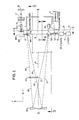
- Figure l is a schematic plan view of a preferred embodiment of the invention, i.e. as seen looking down on Figure 4;
- Figure 2 is a view on the line II-II in Figure l;
- Figure 3 is a view on the line III-III in Figure l;
- Figure 4 is a view on the line IV-IV in Figure l;
- Figure 5 is a view of a mask used in the apparatus of Figures l-4;
- Figure 6 is a fragment of Figure l showing a modification;
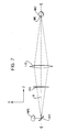
- Figure 7 is a further fragmentary view illustrating an alternative embodiment of the invention;
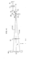
- Figure 8 is a view of an alternative form of mask;
- Figure 9 is a view of an alternative form of mirror; and
- Figure l0 is a fragment of Figure l showing another modification.
- Referring first to Figures l-4, the system provides a light source in the form of a laser l0. A beam l2 from the laser l0 enters a telescope l4 where it is reduced in width. For example, a typical TEA CO₂ pulsed laser would provide a beam of square cross-section with a width of about l inch in each direction. The telescope l4 will reduce this beam to a square beam with sides each about half an inch in width.
- The thus narrowed beam l6 is directed in a direction X onto the surface of a flat circular mirror Ml that is controlled by a galvanometer Gl to rotate about an axis extending in a direction Z perpendicular to the direction X. The mirror Ml reflects the beam l6 onto a second similar mirror M2 that is controlled by a further galvanometer G2 to rotate about an axis extending in the X direction. The mirrors Ml and M2 form a first or "transmitting" assembly, the scanning function of which will be more fully described below.
- As seen in Figure l, a parallel light beam l7 is projected by this transmitting assembly, generally in the direction Z, and onto the surface of a fixed, spherically concave mirror M3. The mirror M3 constitutes a "first imaging element" and serves to reflect a converging, focused beam l8 towards a second or "receiving" assembly that consists of further flat mirrors M4 and M5. The mirror M4 which directly receives the focused beam from the spherical mirror M3 is controlled by a galvanometer G4 to rotate about an axis in a direction Y (perpendicular to both the directions X and Z), and reflects the beam onto the mirror M5. which is controlled by a galvanometer G5 to rotate about an axis extending in the direction Z.
- During its passage from the spherical mirror M3 to the receiving assembly M4, M5, the beam l8 passes through a fixed mask 20 (see Figure 5) to form a modified focused beam l9, i.e. a beam that has been modified by having passed through a window in the mask and hence having adopted the shape of one of the character-defining windows. The
mask 20 is generally opaque, except for rows and columns of windows, each in the shape of acharacter 22, e.g. letters A, B, C etc. The geometry of the system is such, including themask 20 being offset from the principal axis A of the mirror M3 (as best seen in Figures l and 2), that the transmitted beam l7 misses the mask, while the return beam l8 must pass through it to become the modified beam l9. The axis A extends in the direction Z and intersects a line B joining the centre points of the mirrors M2 and M4, i.e. the mirrors that respectively directly transmit the beam l6 to the mirror M3 and directly receive the beam l9 from the mirror M3. These axes A and B define a plane that extends in the X and Z directions. The axis B is spaced along the axis A from the mirror M3 by a distance 2f, where f is the focal length of the mirror M3. Themask 20 is preferably spaced from the mirror M3 by a distance slightly less than the focal length f, e.g. by a distance approximately equal to 0.8f. - As an alternative, the mask need not necessarily be located in the reflected beam l8. Instead it can be located in the transmitted beam l7. As a further alternative, the transmitted beam need not necessarily be a parallel beam. It could be a converging or diverging beam, in which case the beam reflected by the concave mirror M3 could be converging, diverging or parallel.
- From the mirror M5, the beam l9, now conveniently referred to as a working beam 2l (and normally now diverging) passes to a fixed flat mirror M6 and then through a final lens Ll onto a workpiece W. The lens Ll constitutes a "second imaging element." Assuming that the workpiece W has a flat surface for receiving the beam, the lens Ll will preferably be a compound, flat field lens, i.e. one that will ensure that the image of the chosen mask character will be correctly focused on any selected area of the workpiece surface. Should the workpiece surface be appropriately concave, a normal lens could be used.
- The function of the movable mirror Ml of the transmitting assembly is to scan the beam l7 in the X direction, e.g. between paths l7 and l7ʹ shown in Figure l. The mirror M3 ensures that the reflected beam l9 or l9ʹ (focused and modified to carry the character data) arrives at the mirror M4 regardless of whether the transmitted beam followed path l7 or l7ʹ, thus, in effect, regardless of which character in the mask was traversed by the beam. The mirror M4 of the receiving assembly is moved in synchronism with the mirror Ml of the transmitting assembly so as to seek the received beam l9 or l9ʹ and to ensure that it is always reflected as the working beam in the same path 2l extending towards the mirror M5, subject to a superimposed incremental advance that will be described below.
- In a similar manner, the mirrors M2 and M5 synchronously scan and seek the transmitted and received beams in the Y direction. See Figure 4 where the transmitted and received beams are shown coincident, i.e. assuming no simultaneous X direction scanning, the beams being shown as scanned from l7 (transmitted) and l9 (received) to l7ʺ and l9ʺ, respectively. In practice, of course, scanning can take place in the X and Y directions simultaneously, if desired. The galvanometers Gl, G2, G4 and G5 are controlled for this purpose by a control computer C, the receiving assembly always seeking the received beam in the correct direction having regard to its transmitted direction and the ultimate working beam path 2l that it is to follow. In this manner, the beam received by the workpiece can be caused to pass through any selected one of the characters in the mask, without any need to move the mask.
- While in the illustrated embodiment the X scan mirrors come first in the direction of travel of the beam (i.e. mirrors Ml and M4) and the Y scan mirrors follow (mirrors M2 and M5) this sequence can be reversed provided it is done in both the transmitting and receiving assemblies.
- The fixed spherical mirror M3 serves the dual functions of condenser and imager. As the so-called first imaging element, it images the transmitting assembly of mirrors Ml, M2 onto the receiving assembly of mirrors M4, M5. The final lens Ll, on the other hand, the so-called second imaging element, is spaced from the mask and the workpiece and has a focal length such as to ensure that it images the selected character in the
mask 20 onto the workpiece W. - A spherical shape for the mirror M3 is preferred, because it is the cheapest to manufacture, but other concave shapes, such as ellipsoidal, could also be used.
- Assuming that the system is to be used to mark a series of letters extending along at least one row on the surface of the workpiece W, i.e. one letter for each successive pulse of the laser l0, the control C will superimpose on the above described movements of the mirror M4 (for X direction movement) and of the mirror M5 (for Y direction movement), i.e. those necessary to keep the path 2l extending in a fixed direction, further incremental movements that move the path 2l in the manner necessary to achieve the desired distribution of the characters on the workpiece surface.
- Calibration of the positions of the mirrors Ml and M2 of the transmitting assembly can be achieved by means of a plurality (preferably four) sensors 24 (Figure 5) located at convenient places, e.g. the corners, of the
mask 20. The galvanometers Gl and G2 will initially be programmed by the control C to scan until each one of thesesensors 24 has been energised, thus serving to identify various orientations of the transmitted beam. To calibrate the positions of the mirrors M4 and M5 of the receiving assembly, a set ofholes 26 is provided in the mask. As the beam passes through each such hole and is received and detected downstream, e.g. by a sensor (not shown) located at a datum point in the workpiece plane, the orientation of the working beam and hence of the mirrors M4 and M5 becomes known. - If the main laser l0 is unsuited for this calibration purpose, e.g. is too powerful, or of an inappropriate wavelength, a subsidiary laser or
lamp 28 can be used, itsbeam 29 being fed into the system by abeam combining element 30, e.g. a germanium flat, as shown in Figure 6. A low power, Helium Neon, continuous wave laser, emitting visible red light, is a convenient choice as the subsidiary laser. - The invention is not dependent on the use of coherent light as the source, although this will normally be necessary when marking a workpiece. When using the system for display purposes or for marking photographic film the laser l0 can be replaced by a lamp.
- As a further alternative, the mirror M3 can be replaced as the first imaging element by a lens L2, as shown in Figure 7, with the two mirror assemblies Ml, M2, M4, M5 then located symmetrically and equidistantly on opposite sides of such lens, with the
mask 20 preferably, but not necessarily, located downstream of the lens. The preferred distance for each of the mirrors M2 and M4 from the lens L2 will be 2f, where f is the focal length of the lens. This arrangement has the advantage that the mask can be centered on the principal axis A of the lens. However, a significant advantage of the mirror M3 is that it will usually result in a more compact mechanical configuration. - One of the advantages of the present invention is that it enables effective scanning of a fixed mask to select a desired character and the positioning of an image of this character at a chosen location on a workpiece, or screen, or other surface. The term "work surface" is used in the claims that follow to refer generically to these various possibilities.
- However, while the ability of the present invention to operate with a fixed mask is normally advantageous (for mechanical simplicity as well as for speed of operation), of even more value is its ability to operate with both a fixed work surface and a fixed final lens. Indeed, there are some embodiments of the invention in which there is an advantage in having the mask movable. For example, Figure 8 shows a mask in the form of a
disc 32 rotatable about anaxis 33 and carrying two (or more)peripheral series disc 32 and energising the laser when the selected character is in line with the beam. Increased speed of operation can be achieved by increasing the speed of rotation of thedisc 32, or by repeating the alphabet (or other sequence of characters) around the disc. With this movement of the mask, which is assumed to take place in the direction Y where it intersects the beam, it no longer becomes necessary to scan the mirrors of the transmitting assembly in the Y direction. A single flat mirror rotatable about an axis extending in the direction Y, but otherwise similar to the mirror Ml, will be used to provide scanning of the transmitted beam in the X direction. However, both X and Y direction scanning by the galvanometer operated mirrors M4 and M5 of the receiving assembly remain necessary in order to provide means for projecting the received beam into the desired location on the work surface. - Figure 9 shows a further simplification that is especially appropriate for use with embodiments of the invention described in connection with Figure 8, namely the substitution of a series of flat mirror surfaces 36 arranged in an approximately spherical array to furnish a mirror M3ʹ that can be used to replace the mirror M3 as the first imaging element. The reason why this concave array of flat mirror surfaces can be used instead of a true concave surface, is that in the Figure 8 embodiment there will be a relative small number of accessed character positions through which the beam must be scanned.
- Figure l0 shows an alternative device for use as either the transmitting assembly or the receiving assembly or both, namely an acousto-
optical device 40 for scanning either beam in the X and Y directions.
Claims (11)
and wherein the scanning means (Gl, G2) of the transmitting assembly comprises
wherein said further scanning means (G4, G5) of the receiving assembly comprises
and wherein the system includes
and wherein the scanning means of the transmitting assembly comprises
wherein said further scanning means (G4, G5) of the receiving assembly comprises
and wherein the system includes
Applications Claiming Priority (2)
| Application Number | Priority Date | Filing Date | Title |
|---|---|---|---|
| US863439 | 1986-05-15 | ||
| US06/863,439 US4707711A (en) | 1986-05-15 | 1986-05-15 | Character imaging system |
Publications (3)
| Publication Number | Publication Date |
|---|---|
| EP0246801A2 true EP0246801A2 (en) | 1987-11-25 |
| EP0246801A3 EP0246801A3 (en) | 1989-10-04 |
| EP0246801B1 EP0246801B1 (en) | 1993-07-14 |
Family
ID=25341097
Family Applications (1)
| Application Number | Title | Priority Date | Filing Date |
|---|---|---|---|
| EP87304224A Expired - Lifetime EP0246801B1 (en) | 1986-05-15 | 1987-05-12 | Character imaging system |
Country Status (4)
| Country | Link |
|---|---|
| US (1) | US4707711A (en) |
| EP (1) | EP0246801B1 (en) |
| JP (1) | JPH065342B2 (en) |
| DE (1) | DE3786490T2 (en) |
Cited By (2)
| Publication number | Priority date | Publication date | Assignee | Title |
|---|---|---|---|---|
| EP0501624A2 (en) * | 1991-02-25 | 1992-09-02 | Hughes Aircraft Company | System for fabricating micro optical elements |
| WO1997031324A1 (en) * | 1996-02-23 | 1997-08-28 | Spectrum Technologies Ltd. | Laser marking apparatus and methods |
Families Citing this family (5)
| Publication number | Priority date | Publication date | Assignee | Title |
|---|---|---|---|---|
| CA2057047A1 (en) * | 1989-07-27 | 1991-01-28 | Chris R. Redford | Combined ink laser printing of tablets |
| US5463200A (en) * | 1993-02-11 | 1995-10-31 | Lumonics Inc. | Marking of a workpiece by light energy |
| US5977514A (en) | 1997-06-13 | 1999-11-02 | M.A. Hannacolor | Controlled color laser marking of plastics |
| US5999252A (en) * | 1998-07-22 | 1999-12-07 | Seh America, Inc. | Method for marking workpieces |
| US7136084B2 (en) * | 2002-09-17 | 2006-11-14 | Miller Timothy J | Random laser image projector system and method |
Citations (4)
| Publication number | Priority date | Publication date | Assignee | Title |
|---|---|---|---|---|
| US3492926A (en) * | 1966-08-08 | 1970-02-03 | Toshio Asaeda | Device for optically and selectively printing letters |
| US3748015A (en) * | 1971-06-21 | 1973-07-24 | Perkin Elmer Corp | Unit power imaging catoptric anastigmat |
| US3918068A (en) * | 1974-06-14 | 1975-11-04 | Eastman Kodak Co | Distortion correction apparatus for electro-optical reflectors which scan beams to produce images |
| US4503468A (en) * | 1981-10-09 | 1985-03-05 | Northern Telecom Limited | Interactive viewgraph system |
Family Cites Families (4)
| Publication number | Priority date | Publication date | Assignee | Title |
|---|---|---|---|---|
| JPS5034248A (en) * | 1973-07-26 | 1975-04-02 | ||
| US3909103A (en) * | 1974-04-18 | 1975-09-30 | Xerox Corp | Lens scan mechanism |
| JPS51114944A (en) * | 1975-04-02 | 1976-10-09 | Oki Electric Ind Co Ltd | 2 dimensional optical polarizer |
| JPS57179818A (en) * | 1981-04-28 | 1982-11-05 | Hayashibara Takeshi | Lissajous' figure generating device |
-
1986
- 1986-05-15 US US06/863,439 patent/US4707711A/en not_active Expired - Fee Related
-
1987
- 1987-05-12 DE DE87304224T patent/DE3786490T2/en not_active Expired - Fee Related
- 1987-05-12 EP EP87304224A patent/EP0246801B1/en not_active Expired - Lifetime
- 1987-05-15 JP JP62119977A patent/JPH065342B2/en not_active Expired - Lifetime
Patent Citations (4)
| Publication number | Priority date | Publication date | Assignee | Title |
|---|---|---|---|---|
| US3492926A (en) * | 1966-08-08 | 1970-02-03 | Toshio Asaeda | Device for optically and selectively printing letters |
| US3748015A (en) * | 1971-06-21 | 1973-07-24 | Perkin Elmer Corp | Unit power imaging catoptric anastigmat |
| US3918068A (en) * | 1974-06-14 | 1975-11-04 | Eastman Kodak Co | Distortion correction apparatus for electro-optical reflectors which scan beams to produce images |
| US4503468A (en) * | 1981-10-09 | 1985-03-05 | Northern Telecom Limited | Interactive viewgraph system |
Non-Patent Citations (5)
| Title |
|---|
| EOSD. ELEKTRO-OPTICAL SYSTEMS DESIGN, vol. 14, no. 9, September 1982, pages 47-50, Chicago, Illinois, US; J.T. McNANEY: "A versatile high-resolution image scanner" * |
| IBM TECHNICAL DISCLOSURE BULLETIN, vol. 12, no. 10, March 1970, pages 1670-1671, New York, US; R.O. COBB: "Electro-optic printer" * |
| SPIE - LASER PROCESSING OF SEMICONDUCTORS AND HYBRIDS, vol. 611, 21st January 1986, pages 40-47; J.F. HIGGINS: "Laser marking of passive components, hybrids and semiconductors" * |
| XEROX DISCLOSURE JOURNAL, vol. 1, no. 1, January 1976, pages 97-98; G.K. STARKWEATHER: "Scanning system for imaging characters combined with graphic curves" * |
| XEROX DISCLOSURE JOURNAL, vol. 1, no. 9/10, September/Octobr 1976, page 51; I.P. GATES et al.: "Optical character generator system" * |
Cited By (3)
| Publication number | Priority date | Publication date | Assignee | Title |
|---|---|---|---|---|
| EP0501624A2 (en) * | 1991-02-25 | 1992-09-02 | Hughes Aircraft Company | System for fabricating micro optical elements |
| EP0501624A3 (en) * | 1991-02-25 | 1993-02-24 | Hughes Aircraft Company | System for fabricating micro optical elements |
| WO1997031324A1 (en) * | 1996-02-23 | 1997-08-28 | Spectrum Technologies Ltd. | Laser marking apparatus and methods |
Also Published As
| Publication number | Publication date |
|---|---|
| JPH065342B2 (en) | 1994-01-19 |
| EP0246801A3 (en) | 1989-10-04 |
| DE3786490T2 (en) | 1993-12-02 |
| DE3786490D1 (en) | 1993-08-19 |
| EP0246801B1 (en) | 1993-07-14 |
| JPS62284744A (en) | 1987-12-10 |
| US4707711A (en) | 1987-11-17 |
Similar Documents
| Publication | Publication Date | Title |
|---|---|---|
| US3804976A (en) | Multiplexed infrared imaging system | |
| US2600168A (en) | Photoprinting device | |
| EP0538044A2 (en) | Improved print quality laser marker apparatus | |
| GB1107981A (en) | Apparatus for automatically drawing lines | |
| JPS6090321A (en) | Method and apparatus for mark entry of equipment part | |
| JP2014511493A (en) | Target apparatus and method | |
| JPS60227988A (en) | Laser marking device | |
| US4707711A (en) | Character imaging system | |
| EP0573375A1 (en) | Printing techniques using multiple diode lasers | |
| US3687025A (en) | Image spacing system | |
| JP2004090026A (en) | Information writing device | |
| US4668984A (en) | Optical pattern generation technique | |
| US5177632A (en) | Tracking system using a polygon of unique dimension or arbitrary polygon combined with sensors | |
| JPH11156567A (en) | Laser printing device | |
| US3293655A (en) | System for transferring data from a storage medium to a record medium | |
| US4429948A (en) | Optical alignment compensation | |
| JPS60106686A (en) | Laser marking device | |
| CN1025598C (en) | Laser rotary mirror type optical scanning system | |
| JPS6010606B2 (en) | Scanning optical system with high scanning efficiency | |
| JPH0687097B2 (en) | Passive reflective surface tracking laser raster scanner | |
| JPH081101U (en) | Scan timing signal generator | |
| US3382367A (en) | Techniques for forming multiple images of an optical pattern using spherical mirrors | |
| JPS597331A (en) | Optical scanner | |
| US4984008A (en) | Film number writing system | |
| JPS5815768B2 (en) | Sousakou Gakkei |
Legal Events
| Date | Code | Title | Description |
|---|---|---|---|
| PUAI | Public reference made under article 153(3) epc to a published international application that has entered the european phase |
Free format text: ORIGINAL CODE: 0009012 |
|
| AK | Designated contracting states |
Kind code of ref document: A2 Designated state(s): DE FR GB |
|
| PUAL | Search report despatched |
Free format text: ORIGINAL CODE: 0009013 |
|
| RHK1 | Main classification (correction) |
Ipc: G06K 1/12 |
|
| AK | Designated contracting states |
Kind code of ref document: A3 Designated state(s): DE FR GB |
|
| 17P | Request for examination filed |
Effective date: 19900402 |
|
| 17Q | First examination report despatched |
Effective date: 19911004 |
|
| GRAA | (expected) grant |
Free format text: ORIGINAL CODE: 0009210 |
|
| AK | Designated contracting states |
Kind code of ref document: B1 Designated state(s): DE FR GB |
|
| REF | Corresponds to: |
Ref document number: 3786490 Country of ref document: DE Date of ref document: 19930819 |
|
| ET | Fr: translation filed | ||
| PGFP | Annual fee paid to national office [announced via postgrant information from national office to epo] |
Ref country code: GB Payment date: 19940505 Year of fee payment: 8 |
|
| PLBE | No opposition filed within time limit |
Free format text: ORIGINAL CODE: 0009261 |
|
| STAA | Information on the status of an ep patent application or granted ep patent |
Free format text: STATUS: NO OPPOSITION FILED WITHIN TIME LIMIT |
|
| PGFP | Annual fee paid to national office [announced via postgrant information from national office to epo] |
Ref country code: FR Payment date: 19940531 Year of fee payment: 8 |
|
| 26N | No opposition filed | ||
| PG25 | Lapsed in a contracting state [announced via postgrant information from national office to epo] |
Ref country code: GB Effective date: 19950512 |
|
| PGFP | Annual fee paid to national office [announced via postgrant information from national office to epo] |
Ref country code: DE Payment date: 19950526 Year of fee payment: 9 |
|
| GBPC | Gb: european patent ceased through non-payment of renewal fee |
Effective date: 19950512 |
|
| PG25 | Lapsed in a contracting state [announced via postgrant information from national office to epo] |
Ref country code: FR Effective date: 19960229 |
|
| REG | Reference to a national code |
Ref country code: FR Ref legal event code: ST |
|
| REG | Reference to a national code |
Ref country code: FR Ref legal event code: ST |
|
| PG25 | Lapsed in a contracting state [announced via postgrant information from national office to epo] |
Ref country code: DE Effective date: 19970201 |