EP0246517A1 - A method for controlling an operation of a blast furnace - Google Patents
A method for controlling an operation of a blast furnace Download PDFInfo
- Publication number
- EP0246517A1 EP0246517A1 EP87106727A EP87106727A EP0246517A1 EP 0246517 A1 EP0246517 A1 EP 0246517A1 EP 87106727 A EP87106727 A EP 87106727A EP 87106727 A EP87106727 A EP 87106727A EP 0246517 A1 EP0246517 A1 EP 0246517A1
- Authority
- EP
- European Patent Office
- Prior art keywords
- data
- furnace
- burden
- blast furnace
- blast
- Prior art date
- Legal status (The legal status is an assumption and is not a legal conclusion. Google has not performed a legal analysis and makes no representation as to the accuracy of the status listed.)
- Withdrawn
Links
Images


Classifications
-
- G—PHYSICS
- G05—CONTROLLING; REGULATING
- G05B—CONTROL OR REGULATING SYSTEMS IN GENERAL; FUNCTIONAL ELEMENTS OF SUCH SYSTEMS; MONITORING OR TESTING ARRANGEMENTS FOR SUCH SYSTEMS OR ELEMENTS
- G05B23/00—Testing or monitoring of control systems or parts thereof
- G05B23/02—Electric testing or monitoring
- G05B23/0205—Electric testing or monitoring by means of a monitoring system capable of detecting and responding to faults
- G05B23/0218—Electric testing or monitoring by means of a monitoring system capable of detecting and responding to faults characterised by the fault detection method dealing with either existing or incipient faults
- G05B23/0243—Electric testing or monitoring by means of a monitoring system capable of detecting and responding to faults characterised by the fault detection method dealing with either existing or incipient faults model based detection method, e.g. first-principles knowledge model
-
- C—CHEMISTRY; METALLURGY
- C21—METALLURGY OF IRON
- C21B—MANUFACTURE OF IRON OR STEEL
- C21B5/00—Making pig-iron in the blast furnace
- C21B5/006—Automatically controlling the process
-
- G—PHYSICS
- G05—CONTROLLING; REGULATING
- G05B—CONTROL OR REGULATING SYSTEMS IN GENERAL; FUNCTIONAL ELEMENTS OF SUCH SYSTEMS; MONITORING OR TESTING ARRANGEMENTS FOR SUCH SYSTEMS OR ELEMENTS
- G05B13/00—Adaptive control systems, i.e. systems automatically adjusting themselves to have a performance which is optimum according to some preassigned criterion
- G05B13/02—Adaptive control systems, i.e. systems automatically adjusting themselves to have a performance which is optimum according to some preassigned criterion electric
- G05B13/0265—Adaptive control systems, i.e. systems automatically adjusting themselves to have a performance which is optimum according to some preassigned criterion electric the criterion being a learning criterion
- G05B13/028—Adaptive control systems, i.e. systems automatically adjusting themselves to have a performance which is optimum according to some preassigned criterion electric the criterion being a learning criterion using expert systems only
-
- G—PHYSICS
- G05—CONTROLLING; REGULATING
- G05B—CONTROL OR REGULATING SYSTEMS IN GENERAL; FUNCTIONAL ELEMENTS OF SUCH SYSTEMS; MONITORING OR TESTING ARRANGEMENTS FOR SUCH SYSTEMS OR ELEMENTS
- G05B23/00—Testing or monitoring of control systems or parts thereof
- G05B23/02—Electric testing or monitoring
- G05B23/0205—Electric testing or monitoring by means of a monitoring system capable of detecting and responding to faults
- G05B23/0259—Electric testing or monitoring by means of a monitoring system capable of detecting and responding to faults characterized by the response to fault detection
- G05B23/0286—Modifications to the monitored process, e.g. stopping operation or adapting control
- G05B23/0289—Reconfiguration to prevent failure, e.g. usually as a reaction to incipient failure detection
-
- Y—GENERAL TAGGING OF NEW TECHNOLOGICAL DEVELOPMENTS; GENERAL TAGGING OF CROSS-SECTIONAL TECHNOLOGIES SPANNING OVER SEVERAL SECTIONS OF THE IPC; TECHNICAL SUBJECTS COVERED BY FORMER USPC CROSS-REFERENCE ART COLLECTIONS [XRACs] AND DIGESTS
- Y10—TECHNICAL SUBJECTS COVERED BY FORMER USPC
- Y10S—TECHNICAL SUBJECTS COVERED BY FORMER USPC CROSS-REFERENCE ART COLLECTIONS [XRACs] AND DIGESTS
- Y10S706/00—Data processing: artificial intelligence
- Y10S706/902—Application using ai with detail of the ai system
- Y10S706/903—Control
- Y10S706/906—Process plant
Definitions
- the present invention relates to a method for controlling the operation of a blast furnace, and particularly to a method for diagnosing the furnace operating conditions, based on information output from sensor means provided in the blast furnace.
- a method for controlling an operation of a blast furnace which comprises the steps of:
- F ig. 1 schematically represents a method for diagnosing blast furnace operating conditions according to the present invention.
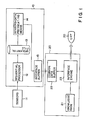
- Reference numeral 10 denotes a large-scale computer.
- Computer 10 includes sequential processing means 12, which sequentially processes the data output from various sensor means 11, sequential filing means 13, sensor-data processing means 14, and interface buffer means 15.
- Reference numeral 20 denotes a small-scale computer which includes knowledge base means 21 for diagnosing the operating conditions of a blast furnace, common data buffer means 22, and inference engine means 23.
- Reference numeral 30 denotes a cathode ray tube (CRT) which displays the results calculated by the inference engine means.
- CTR cathode ray tube
- F ig. 2 schematically illustrates an apparatus for performing the method according to the present invention.
- Reference numerals lla, llb, and llc each indicate sensors corresponding to sensor means 11 shown in Fig. 1.
- Large-scale computer 10 includes the following devices:
- CPU 42 and ROM 43 which store the programs to be executed by CPU 42, constitute sequential processing means 12 and sensor-data processing means 14, both shown in F ig. 1.
- RAM 44 constitutes sequential filing means 13 shown in Fig. 1.
- RAM 45 temporarily stores the data output from the sensor means.
- RAM 45 and interface 46 constitute interface buffer means 15, shown in F ig. 1.
- small-scale computer 20 includes keyboard 47, interface 48, CPU 49, ROM 50, RAMs 51 and 52, and interface 53.
- CPU 49 and ROM 50 which store the programs to be executed by CPU 49, constitute inference engine means 23 shown in Fig. 1.
- RAM 51 constitutes knowledge base means 21, also shown in Fig. 1.
- the data stored in RAM 51 can be altered by operating keyboard 47. New data can be added to these data by inputting the new data by keyboard 47 via interface 48.
- RAM 52 constitutes common data buffer means 22, as shown in Fig. l.
- the data stored in RAM 45 of large-scale computer 10 are transferred to RAM 52 via interface 46.
- the results obtained by CPU 49 are supplied to CRT 30 through interface 53, and are displayed.
- Sensor means 11 detecting channeling and ship are largely classified into those for checking burden descent behavior, those for detecting pressure, those for detecting temperatures, and those for detecting gas compositions.
- residual slag data obtained from information regarding pressure and temperature, also affect the channeling and slip.
- Table 1 shows the sensor means which detect the various conditions in the furnace.
- the sensor means are not limited to those listed in Table 1.
- a vertical probe, a differential type burden thickness and speed meter and a tuyere-nose-flame brightness measuring device can be used.
- the step of processing the first data includes the following data-processings:
- the second data comprises:
- the items forming the second data are not limited to those described above.
- the residual slag (1) is affected by a burden distribution device, and the residual slag (2) is not affected by the same.
- the second data are compared with the standard data to prepare true-and-false data.
- the standard data are composed of the average of those measured on a previous day, the average of those measured for an hour in stable operation, and a theoretical value.
- burden descent behavior for example, if the burden descent speed (a present moment value) minus burden descent speed (a previous day average value) is less than -K l (where K 1 is a constant) with respect to the four directions of sounding, the true-and-false data are "Burden descent speed is slow and a certain factor value is CF 201 ⁇ " Thus, the true-and-false data contain this certainty factor.
- the items of true-and-false data, thus obtained, are listed in Table 3.
- the true-and-false data include, in addition to data corresponding to the second data, data 361, based on human judgement, "Residual slag is great”, and data 371 based on a previous alarm, "The previous alarm is high", where a previous alarm is a total judgement made in the previous inference process.
- the knowledge base is composed of knowledge units corresponding to the true-and-false data.
- Each knowledge unit indicates an operator's knowledge and experience on the operating production process, in the form of "if ..., then .".
- the reliability of inference is raised by introducing to the inference process a certainty factor (CF) which indicates the uncertainty degree of each rule for the operating production process.
- CF certainty factor
- the processed results indicated by "OR” are the sum of the true-and-false data, into which CF values are taken, not a logical sum.
- the processed results indicated by "AND” are a logical product.
- the inference results are a sum 400 of the items of data used in the inference process, i.e., the fourth data, which is accompanied by a CF value and which indicates: "Burden descent is out of successful operation".
- the inference results are a sum 410 of the items of data used in the inference, i.e., the fourth data, which is accompanied by a CF value summed, and which indicates "Pressure dispersion is large".
- the inference results obtained from the true-and-false data of.321 to 324, are also a sum 420, or the fourth data.
- the fourth data are accompanied by a summed-up CF value and indicate: "Temperature dispersion is large”.
- the inference results obtained from the true-and-false data of 331 and 332 are a sum 430, or the fourth data.
- the fourth data are accompanied by a summed-up CF value and indicate: "Gas utilization ratio is falling".
- the burden descent behavior and the pressure rules affect most slips and channelings.
- the inference results, or a sum 500 is accompanied by a-CF value and indicates: "Channeling (sensor judgement)" (500).
- Diagnosis of slip and hanging is made fundamentally in the same manner as the diagnosis of channeling, except that the CF values for slip and hanging are different from those for channeling.
- the certainty of foreseeing slip (CFf) and the certainty of foreseeing channeling (CFf) are obtained by carrying out inferences in three steps that is, the step of obtaining the fourth data from the true-and-false (third) data; the step of obtaining the fifth data from the fourth data; and the step of making the total judgement from the fifth data.
- This step-by- step inference gives the following advantages:
- the method of inference described in the embodiment is more desirable, by reason of the aforementioned (1), (2), and (3), than the substitutions.
- the furnace is controlled in accordance with the results (CFs, CF c f ) of the judgement.
- the control is achieved by reducing the blast supplied through tuyeres, by changing the distribution of burden charged through a furnace top, by controlling the fuel ratio, by adjusting the composition of slag or, by increase or decrease of the temperature of the tuyere-nose flame.
- the reduction of the blast is effective, particularly for channeling.
- the reduction of blast is standardized according to probabilities of slip.
- the reduction is set, for example, to 300 Nm 3 /min. (4 to 5% of total blast volume) when CFf is 60 to 80%, and to 500 Nm 3 /min. (7 to 8% of total blast amount) when CFf is greater than 80 % .
- Diagnosis of slip was carried out for a 4 663 m 3- blast furnace on the operating conditions shown in Table 6. The diagnosis is made every 2nd minute. The results of the diagnosis at 12°10' are shown in Table 7.
- the data-sampling period was 10 days.
- the actual slip ratio is given by formula of N/F, where N is the number of highest CFf levels obtained during the 10-day period, and F is the number of slips occurring during the same period. Each of these levels is highest of the fifteen levels detected within thirty minutes. They were counted at a ten-percent pitch.
Abstract
Description
- The present invention relates to a method for controlling the operation of a blast furnace, and particularly to a method for diagnosing the furnace operating conditions, based on information output from sensor means provided in the blast furnace.
- In recent times, various methods have been proposed for the diagnosing and controlling of the operation of a blast furnace. Japanese Patent Disclosure (KOKAI) No. 84-64705, for example, describes a method wherein:
- (a) factors, which are clearly known on the basis of accumulated experience, are derived from data output from various sensors;
- (b) these factors are, in connection with the phenomena occurring in the furnace, arranged in order and numerically evaluated; and
- (c) from the factors thus arranged and evaluated in both a short and long term, the operating conditions of the furnace are detected.
- This method, however, is disadvantageous in that it requires an analysis model to be maintained by means of modifications thereto in compliance with the changes the blast furnace undergoes throughout its life. Moreover, the modification itself is quite a time-consuming and complicated task, as the analysis model is quite complex.
- It is an object of the present invention to provide a method for diagnosing a blast furnace operation, wherein an analysis model is easily modified in compliance with the change the blast furnace undergoes during its life.
- According to the present invention, a method is provided for controlling an operation of a blast furnace, which comprises the steps of:
- storing first data output from sensor means provided in the blast furnace into a central processing unit (CPU);
- processing said first data, thereby preparing second data showing the operating conditions in the blast furnace; and
- preparing true-and-false data, as the third data, by comparing said second data with standard data, and inferring a furnace operation condition, from the third data and a knowledge base formed by accumulated experience on the operation of the blast furnace.
- This invention can be more fully understood from the following detailed description when taken in conjunction with the accompanying drawings, in which:
- Fig. 1 is a schematic representation showing a method for diagnosing furnace operating conditions according to the present invention;
- Fig. 2 is a schematic block representation of an apparatus for performing the method of the present invention;
- Fig. 3 is a flowchart showing the method of the present invention;
- Fig. 4 is a schematic representation illustrating the processes of inferring operating conditions of a blast furnace according to the present invention;
- Fig. 5 is a graphic representation showing the results obtained by an example of the present invention; and
- Fig. 6 is a graphic representation showing the relationship between the diagnosis results of an example obtained by the present invention and the actual operating conditions.
- An embodiment according to the present invention will now be described, with reference to Figs. 1 to 4.
- Fig. 1 schematically represents a method for diagnosing blast furnace operating conditions according to the present invention.
Reference numeral 10 denotes a large-scale computer.Computer 10 includes sequential processing means 12, which sequentially processes the data output from various sensor means 11, sequential filing means 13, sensor-data processing means 14, and interface buffer means 15.Reference numeral 20 denotes a small-scale computer which includes knowledge base means 21 for diagnosing the operating conditions of a blast furnace, common data buffer means 22, and inference engine means 23.Reference numeral 30 denotes a cathode ray tube (CRT) which displays the results calculated by the inference engine means. - Fig. 2 schematically illustrates an apparatus for performing the method according to the present invention. Reference numerals lla, llb, and llc each indicate sensors corresponding to sensor means 11 shown in Fig. 1. Large-
scale computer 10 includes the following devices: - 41: interface;
- 42: CPU;
- 43: read-only memory (ROM) storing program;
- 44 and 45: random access memories (RAMs); and
- 46: interface.
-
CPU 42 andROM 43, which store the programs to be executed byCPU 42, constitute sequential processing means 12 and sensor-data processing means 14, both shown in Fig. 1.RAM 44 constitutes sequential filing means 13 shown in Fig. 1.RAM 45 temporarily stores the data output from the sensor means.RAM 45 andinterface 46 constitute interface buffer means 15, shown in Fig. 1. - In Fig. 2, small-
scale computer 20 includeskeyboard 47,interface 48,CPU 49,ROM 50,RAMs interface 53.CPU 49 andROM 50, which store the programs to be executed byCPU 49, constitute inference engine means 23 shown in Fig. 1.RAM 51 constitutes knowledge base means 21, also shown in Fig. 1. The data stored inRAM 51 can be altered byoperating keyboard 47. New data can be added to these data by inputting the new data bykeyboard 47 viainterface 48.RAM 52 constitutes common data buffer means 22, as shown in Fig. l. The data stored inRAM 45 of large-scale computer 10 are transferred toRAM 52 viainterface 46. The results obtained byCPU 49 are supplied to CRT 30 throughinterface 53, and are displayed. The operation of the embodiment according to the present invention will now be described, in conjunction with the flowchart shown in Fig. 3. - (1) Firstly, the first data, output from sensor means 11, are read in a predetermined sequence by sequential processing means 12, and then stored in sequential filing means 13 (Step 1). Actually, this work is completed by supplying the data from sensors lla, llb, and llc to
RAM 44 throughinterface 41 under the control ofCPU 42. - (2) The first data stored in sequential filing means 12 is processed by
CPU 42, thereby forming second data showing furnace operating conditions. This processing step produces data showing a rate of change, comparison of levels, dispersion of values and an integral value of the first data within a designated time interval. This work is actually carried out by CPU 42 (Step 2). - (3) The second data obtained in
Step 2 are compared byCPU 42 with standard data, thereby providing true-and-false data. The true-and-false data are stored in interface buffer means 15. More specifically, these data are stored inRAM 45 in Fig. 2 (Step 3). - (4) The true-and-false data stored in interface buffer means 15 are transferred to common data buffer means 22 (Step 4). More precisely, the stored data in
RAM 45 are transferred toRAM 52. - (5) Inference engine means 23 infers the operating conditions of the furnace, based on the data stored in knowledge base means 21 and the true-and-false data stored in common data buffer means 24 (Step 5). This work is achieved as
CPU 49 executes the program designated by the data stored inRAMs - (6) Subsequently, the total judgement made by
CP U 49 is supplied toCRT 30 throughinterface 53 and then displayed (Step 6). - (7) Then, it is determined whether a stop signal has been given or not. If YES, the processing is stopped. If NOT, it returns to
Step 1. In the latter case, the aforementioned Steps 1-7 are repeated at predetermined intervals of, for example, 2 minutes. - Sensor means 11 detecting channeling and ship are largely classified into those for checking burden descent behavior, those for detecting pressure, those for detecting temperatures, and those for detecting gas compositions. In addition, residual slag data, obtained from information regarding pressure and temperature, also affect the channeling and slip. Table 1 shows the sensor means which detect the various conditions in the furnace.

- The sensor means are not limited to those listed in Table 1. In addition to those, a vertical probe, a differential type burden thickness and speed meter and a tuyere-nose-flame brightness measuring device can be used.
- The step of processing the first data includes the following data-processings:
- (a) Calculating the first regression coefficient for the past 30 minutes:
- This is applicable to the temperature measured by horizontal probes, and top gas utilization ratio, and the temperature measured by under-bell probes.
- (b) Calculating the balance between a value measured at present and that measured tk minutes before:
- This is applicable to the shaft temperature.
- (c) Calculating the balance between the two values obtained by the first regression coefficient formula by substitution of two values measured at present and tk minutes before:
- This is applicable to the top gas utilization ratio.
- (d) Calculating the balance between two values obtained at present and tk minutes before:
- This is applicable to burden decent speed, pressure loss, shaft temperature, burden temperature at horizontal probe levels, shaft pressure and blast pressure.
- (e) Calculating a standard deviation:
- This is applicable to burden descent speed and pressure loss.
- (f) Integrating a deviation from a theoretical value:
- This is applicable to burden descent speed.
- The second data, which have been pretreated, are shown in Table 2.

- The second data comprises:
- Data 201 to 204 regarding burden descent behavior 200;
- Data 211 to 214 regarding pressure 210;
- Data 221 to 214 regarding temperature 220;
- Data 231 and 232 regarding gas constituent 230;
- Data 241 and 242 regarding residual slag (1) 240; and
- Data 251 to 253 regarding residual slag (2) 250.
- The items forming the second data are not limited to those described above. The residual slag (1) is affected by a burden distribution device, and the residual slag (2) is not affected by the same.
- The second data are compared with the standard data to prepare true-and-false data. The standard data are composed of the average of those measured on a previous day, the average of those measured for an hour in stable operation, and a theoretical value.
- In the case of burden descent behavior, for example, if the burden descent speed (a present moment value) minus burden descent speed (a previous day average value) is less than -Kl (where K1 is a constant) with respect to the four directions of sounding, the true-and-false data are "Burden descent speed is slow and a certain factor value is CF201·" Thus, the true-and-false data contain this certainty factor.
- In the case of in-furnace pressure loss, if the "pressure loss (a present moment value) minus pressure loss (a previous day average value) is larger than K2 (where K2 is a constant)", the true-and-false data are "Pressure loss is large and a certainty factor value is CF211·" The true-and-false data contain this certainty factor.
- The items of true-and-false data, thus obtained, are listed in Table 3. The true-and-false data include, in addition to data corresponding to the second data,
data 361, based on human judgement, "Residual slag is great", anddata 371 based on a previous alarm, "The previous alarm is high", where a previous alarm is a total judgement made in the previous inference process.

- The knowledge base is composed of knowledge units corresponding to the true-and-false data. Each knowledge unit indicates an operator's knowledge and experience on the operating production process, in the form of "if ..., then ....". In this embodiment, the reliability of inference is raised by introducing to the inference process a certainty factor (CF) which indicates the uncertainty degree of each rule for the operating production process.
- In the case of, for example, a rule for burden descent, the expression is: "If burden descent speed is slow, then, the operation has tendency toward channeling".
- In the case of a rule for pressure loss, the expression is: "If pressure loss is large, then, the operation has a tendency toward channeling".
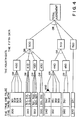
- An example of inference of judgement will now be given with reference to Fig. 4.
- The processed results indicated by "OR" are the sum of the true-and-false data, into which CF values are taken, not a logical sum. The processed results indicated by "AND" are a logical product.
- (1) The fourth data are obtained by inferences, based on the true-and-false data (the third data) and the knowledge base, and also based on CF values.
- In the case of a burden descent rule, inference is performed, in combination with consideration of the CF values, on the basis of both the knowledge base, and the true-and-false data which are composed of:
- "Burden descent speed is slow" (301);
- "Dispersion of burden descent speed is large" (302) ;
- "Delay of burden descent is large" (303);
- "Average of burden descent speeds is slow" (304).
- Thus, the inference results are a
sum 400 of the items of data used in the inference process, i.e., the fourth data, which is accompanied by a CF value and which indicates: "Burden descent is out of successful operation". - In case of a pressure loss rule, inference is performed- in the same manner corresponding CF values, on the basis of both the knowledge base and the true-and-false data of 311 to 314. Thus, the inference results are a
sum 410 of the items of data used in the inference, i.e., the fourth data, which is accompanied by a CF value summed, and which indicates "Pressure dispersion is large". - In the case of a temperature rule, the inference results, obtained from the true-and-false data of.321 to 324, are also a
sum 420, or the fourth data. The fourth data are accompanied by a summed-up CF value and indicate: "Temperature dispersion is large". - In the case of a gas utilization rule, the inference results obtained from the true-and-false data of 331 and 332 are a
sum 430, or the fourth data. The fourth data are accompanied by a summed-up CF value and indicate: "Gas utilization ratio is falling". - In the case of the inference regarding the amount of residual slag, based on sensor information (440) "Residual slag is great", which is processed by sensor judgement, a logical product is obtained from the following:
- (1) "Temperature of in-furnace central area, measured by under-bell probes set at a furnace throat level, is falling" (341).
- (2) "Temperature of in-furnace peripheral area, measured by under-bell probes set at a furnace throat level, is rising" (342).
- If either of the two is false, the logical product is false. Except for this respect, the inference is performed in the same manner as described in the foregoing.
- In the case of a residual slag rule other than the- above-mentioned, the following true-and-false data are used:
- (1) "Rise of shaft pressure is n or more" (351).
- (2) "Blast-pressure is rapidly rising" (352).
- (3) "Residual slag is great" (353).
- Moreover, in some rules for residual slag, human judgement based on the operator's judgement is incorporated. From this processing,
data 450, which constitutes the fourth data, is obtained. These data represent whether residual slag is great (450) (human judgement).
- Among those rules for burden descent behavior, pressure loss, temperature, gas composition and residual slag, the burden descent behavior and the pressure rules affect most slips and channelings. There are three residual rules: the rule for residual slag (1), the rule for residual slag (2), and the rule for residual rule (3). This is because a single rule for residual slag (1) is insufficient when an operation of a burden distribution device is modified. Human judgement of residual slag (3) can be replaced by slag flow meter judgement.
- An inference is performed, in consideration of the summed-up CF value accompanied by each of the results inferred in the fourth data-making process in respect to the burden descent behavior, pressure loss temperature and gas composition, on the basis of the following:
- "Burden descent behavior is out of successful operation" (400);
- "In-furnace pressure dispersion is large" (410);
- "In-furnace temperature dispersion is large" (420);
- "Gas utilization ratio is falling" (430).
- Thus, the inference results, or a
sum 500, i.e., the fifth data, is accompanied by a-CF value and indicates: "Channeling (sensor judgement)" (500). - In the same manner, an inference is performed, in consideration of the sum of the CF values accompanied by the results inferred in the process of making the fourth data in respect to the rest of the items on the basis of the following:
- "Residual slag is great (sensor judgement)" (440);
- "Residual slag is great (human judgement)" (450).
- Thus, the inference results or
data 510, i.e., - Finally, an inference is performed, in consideration of the summed-up CF values accompanying the results inferred in the process of making the fifth data, on the basis of the following:
- "Channeling (sensor judgement)" (500);
- "Channeling (residual slag judgement)" (510);
- "Channeling (previous alarm)" (520).
- The inference results, or a sum of these items of data indicates "Channeling (total judgement)".
- The embodiment explained above is for the diagnosis of channeling. Diagnosis of slip and hanging is made fundamentally in the same manner as the diagnosis of channeling, except that the CF values for slip and hanging are different from those for channeling.
- In the embodiment, the certainty of foreseeing slip (CFf) and the certainty of foreseeing channeling (CFf) are obtained by carrying out inferences in three steps that is, the step of obtaining the fourth data from the true-and-false (third) data; the step of obtaining the fifth data from the fourth data; and the step of making the total judgement from the fifth data. This step-by- step inference gives the following advantages:
- (1) Inference becomes speedy.
- (2) Causes for slip and channeling are easy to clarify.
- (3) CF values can be well maintained, even if modified.
- The following substitutions can be employed in the invention:
- (a) a method wherein a total judgement is inferred directly from the true-and-false (third) data;
- (b) a method wherein a total judgement is inferred from the fifth data prepared directly on the basis of the true-and-false (third) data; and
- (c) a method wherein a total judgement is made directly from the fourth data prepared on the basis of the true-and-false (third) data.
- However, the method of inference described in the embodiment is more desirable, by reason of the aforementioned (1), (2), and (3), than the substitutions.
- When a total judgement is made, the furnace is controlled in accordance with the results (CFs, CFc f) of the judgement. The control is achieved by reducing the blast supplied through tuyeres, by changing the distribution of burden charged through a furnace top, by controlling the fuel ratio, by adjusting the composition of slag or, by increase or decrease of the temperature of the tuyere-nose flame. The reduction of the blast is effective, particularly for channeling.
- The reduction of blast is standardized according to probabilities of slip. The reduction is set, for example, to 300 Nm3/min. (4 to 5% of total blast volume) when CFf is 60 to 80%, and to 500 Nm3/min. (7 to 8% of total blast amount) when CFf is greater than 80%.
- Diagnosis of slip was carried out for a 4 663 m3- blast furnace on the operating conditions shown in Table 6. The diagnosis is made every 2nd minute. The results of the diagnosis at 12°10' are shown in Table 7.


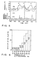
- Diagnosis of channeling was carried out every 2nd minute for 3 hours. The blast furnace was operated under the conditions shown in Table 6. The results are represented in Fig. 5, wherein (a) designates the burden descent behavior, (b) denotes the probability of slip (CFf), and (c) represents the probability of channeling (CFc f) - all in relation to the lapse of time.
- Remarkable increases of the burden descent speed occurred at points of X, Y, and Z where the probability of slip (CFf) was high. This teaches that slips have occurred. Thus, a close relationship was proved to exist between CFf and slip occurrence.
- The relationship between probability of slip (CFl) and the conditions are the same as in the case of Example 1. The results of the diagnosis at 12°10' are shown in Table 8.

- Diagnosis of slip and channeling was carried out. The actual slip occurrence ratio is shown in Fig. 6.
- The data-sampling period was 10 days. The actual slip ratio is given by formula of N/F, where N is the number of highest CFf levels obtained during the 10-day period, and F is the number of slips occurring during the same period. Each of these levels is highest of the fifteen levels detected within thirty minutes. They were counted at a ten-percent pitch.
- When CFf was greater than 60%, it was ascertained that slips occurred with a probability of greater than 70%.
the fifth data, are accompanied by a CF value summed up in the inference process and indicates: "Channeling (residual slag)" (510).

Claims (11)
Applications Claiming Priority (2)
| Application Number | Priority Date | Filing Date | Title |
|---|---|---|---|
| JP61113794A JPS62270712A (en) | 1986-05-20 | 1986-05-20 | System for detecting condition of blast furnace |
| JP113794/86 | 1986-05-20 |
Publications (1)
| Publication Number | Publication Date |
|---|---|
| EP0246517A1 true EP0246517A1 (en) | 1987-11-25 |
Family
ID=14621252
Family Applications (1)
| Application Number | Title | Priority Date | Filing Date |
|---|---|---|---|
| EP87106727A Withdrawn EP0246517A1 (en) | 1986-05-20 | 1987-05-08 | A method for controlling an operation of a blast furnace |
Country Status (5)
| Country | Link |
|---|---|
| US (1) | US4901247A (en) |
| EP (1) | EP0246517A1 (en) |
| JP (1) | JPS62270712A (en) |
| CN (1) | CN87103633A (en) |
| BR (1) | BR8702539A (en) |
Cited By (8)
| Publication number | Priority date | Publication date | Assignee | Title |
|---|---|---|---|---|
| GB2217069A (en) * | 1988-03-17 | 1989-10-18 | Toshiba Kk | Real time expert computer system |
| EP0375282A2 (en) * | 1988-12-20 | 1990-06-27 | Nippon Steel Corporation | Blast furnace operation management method and apparatus |
| EP0389132A2 (en) * | 1989-03-20 | 1990-09-26 | Hitachi, Ltd. | A control system for an industrial plant, a display device for such a control system, and a method of controlling an industrial plant |
| DE4108310A1 (en) * | 1990-03-14 | 1991-09-26 | Hitachi Ltd | Knowledge base processing and expert system - stores indices representing certainty grade of casual relationship between occurrence and others relevant to it |
| GB2245382A (en) * | 1990-04-28 | 1992-01-02 | Motorola Inc | Automotive diagnostic system |
| EP0516534A1 (en) * | 1991-05-28 | 1992-12-02 | European Gas Turbines Sa | Method and device for monitoring an apparatus working under variable conditions |
| WO1995013572A1 (en) * | 1993-11-09 | 1995-05-18 | Siemens Aktiengesellschaft | Process and device for the analysis of a diagnosis of the operating condition of a technical plant |
| DE19502554A1 (en) * | 1994-02-28 | 1995-08-31 | Fujitsu Ltd | Information processing using knowledge base and neural network |
Families Citing this family (18)
| Publication number | Priority date | Publication date | Assignee | Title |
|---|---|---|---|---|
| US5121496A (en) * | 1988-07-25 | 1992-06-09 | Westinghouse Electric Corp. | Method for creating, maintaining and using an expert system by recursively modifying calibration file and merging with standard file |
| US5099438A (en) * | 1989-08-28 | 1992-03-24 | Ucar Carbon Technology Corporation | Method for on-line monitoring and control of the performance of an electric arc furnace |
| CN1038146C (en) * | 1993-07-21 | 1998-04-22 | 首钢总公司 | Computerized blast furnace smelting expert system method |
| US5521844A (en) * | 1993-09-10 | 1996-05-28 | Beloit Corporation | Printing press monitoring and advising system |
| US5572670A (en) * | 1994-01-10 | 1996-11-05 | Storage Technology Corporation | Bi-directional translator for diagnostic sensor data |
| CN1039498C (en) * | 1995-11-23 | 1998-08-12 | 宝山钢铁(集团)公司 | Blast furnace comprhensive deterministic system |
| CN1052758C (en) * | 1997-06-13 | 2000-05-24 | 冶金工业部自动化研究院 | Blast furnace operating consulting system |
| US6389330B1 (en) | 1997-12-18 | 2002-05-14 | Reuter-Stokes, Inc. | Combustion diagnostics method and system |
| US6341519B1 (en) | 1998-11-06 | 2002-01-29 | Reuter-Stokes, Inc. | Gas-sensing probe for use in a combustor |
| US6277268B1 (en) | 1998-11-06 | 2001-08-21 | Reuter-Stokes, Inc. | System and method for monitoring gaseous combustibles in fossil combustors |
| US7128818B2 (en) * | 2002-01-09 | 2006-10-31 | General Electric Company | Method and apparatus for monitoring gases in a combustion system |
| KR101032531B1 (en) | 2008-11-07 | 2011-05-04 | 주식회사 포스코 | System and method for visualizing temperature distribution in blast furnace |
| GB0911836D0 (en) * | 2009-07-08 | 2009-08-19 | Optimized Systems And Solution | Machine operation management |
| CN101792836B (en) * | 2010-03-25 | 2011-08-31 | 济南领航机械设备有限公司 | Blast furnace bell-less furnace top failure diagnosis forecasting system |
| CN102096404B (en) * | 2010-12-31 | 2013-11-20 | 中冶南方工程技术有限公司 | Bell-less string tank furnace top charging material software tracker and control method thereof |
| CN102703626B (en) * | 2012-06-16 | 2014-01-15 | 冶金自动化研究设计院 | Intelligent optimal control system for CO2 emission of blast furnace |
| CN102816883B (en) * | 2012-06-18 | 2013-12-11 | 北京科技大学 | Radar, video and laser system combined device for measuring blast furnace burden surface |
| CN105483301B (en) * | 2015-12-01 | 2017-06-13 | 中冶南方工程技术有限公司 | Charging of blast furnace charge personal distance control method |
Citations (2)
| Publication number | Priority date | Publication date | Assignee | Title |
|---|---|---|---|---|
| US4248625A (en) * | 1979-08-06 | 1981-02-03 | Kawasaki Steel Corporation | Method of operating a blast furnace |
| GB2142206A (en) * | 1983-06-24 | 1985-01-09 | Atomic Energy Authority Uk | Monitoring system |
Family Cites Families (3)
| Publication number | Priority date | Publication date | Assignee | Title |
|---|---|---|---|---|
| GB142206A (en) * | 1919-02-06 | 1920-05-06 | William Mann | Improved process relating to the decomposition of hydrocarbons and other substances in the liquid and, or, vapour phases |
| JPS5964705A (en) * | 1982-10-01 | 1984-04-12 | Nippon Kokan Kk <Nkk> | Method of detecting condition of blast furnace |
| JPH0789283B2 (en) * | 1984-11-02 | 1995-09-27 | 株式会社日立製作所 | Formula processing control system |
-
1986
- 1986-05-20 JP JP61113794A patent/JPS62270712A/en active Granted
-
1987
- 1987-05-08 EP EP87106727A patent/EP0246517A1/en not_active Withdrawn
- 1987-05-19 BR BR8702539A patent/BR8702539A/en not_active IP Right Cessation
- 1987-05-19 CN CN198787103633A patent/CN87103633A/en active Pending
-
1989
- 1989-08-07 US US07/391,639 patent/US4901247A/en not_active Expired - Fee Related
Patent Citations (2)
| Publication number | Priority date | Publication date | Assignee | Title |
|---|---|---|---|---|
| US4248625A (en) * | 1979-08-06 | 1981-02-03 | Kawasaki Steel Corporation | Method of operating a blast furnace |
| GB2142206A (en) * | 1983-06-24 | 1985-01-09 | Atomic Energy Authority Uk | Monitoring system |
Non-Patent Citations (3)
| Title |
|---|
| AUTOMATISIERUNGSTECHNIK, vol. 33, no. 2, February 1985, pages 45-52; B. BIEKER et al.: "Fuzzy Regelungen und Linguistische Regelalgorithmen - eine kritische Bestandsaufnahme" * |
| PATENT ABSTRACTS OF JAPAN, vol. 8, no. 162 (C-235)[1599], 26th July 1984; & JP-A-59 64 705 (NIPPON KOKAN K.K.) 12-04-1984 * |
| PROCEEDINGS IECON'84 - 1984 INTERNATIONAL CNFERENCE ON INDUSTRIAL ELECTRONICS, CONTROL AND INSTRUMENTATION, Tokyo, 22nd-26th October 1984, vol. 2, pages 883-888; M. SAITO et al.: "An automatic diagnosing system for the blast furnace operating conditions" * |
Cited By (20)
| Publication number | Priority date | Publication date | Assignee | Title |
|---|---|---|---|---|
| GB2217069B (en) * | 1988-03-17 | 1993-02-24 | Toshiba Kk | Real time computer system |
| DE3908879A1 (en) * | 1988-03-17 | 1989-11-02 | Toshiba Kawasaki Kk | REAL-TIME EXPERT COMPUTER SYSTEM |
| GB2217069A (en) * | 1988-03-17 | 1989-10-18 | Toshiba Kk | Real time expert computer system |
| EP0375282A2 (en) * | 1988-12-20 | 1990-06-27 | Nippon Steel Corporation | Blast furnace operation management method and apparatus |
| EP0375282A3 (en) * | 1988-12-20 | 1991-05-15 | Nippon Steel Corporation | Blast furnace operation management method and apparatus |
| EP0641863A1 (en) * | 1988-12-20 | 1995-03-08 | Nippon Steel Corporation | Blast furnace operation management method and apparatus |
| EP0542717A1 (en) * | 1988-12-20 | 1993-05-19 | Nippon Steel Corporation | Blast furnace operation management method and apparatus |
| EP0389132A2 (en) * | 1989-03-20 | 1990-09-26 | Hitachi, Ltd. | A control system for an industrial plant, a display device for such a control system, and a method of controlling an industrial plant |
| EP0389132A3 (en) * | 1989-03-20 | 1992-04-15 | Hitachi, Ltd. | A control system for an industrial plant, a display device for such a control system, and a method of controlling an industrial plant |
| DE4108310A1 (en) * | 1990-03-14 | 1991-09-26 | Hitachi Ltd | Knowledge base processing and expert system - stores indices representing certainty grade of casual relationship between occurrence and others relevant to it |
| US5493729A (en) * | 1990-03-14 | 1996-02-20 | Hitachi, Ltd. | Knowledge data base processing system and expert system |
| DE4108310C2 (en) * | 1990-03-14 | 1998-10-22 | Hitachi Ltd | Processing system for a knowledge base in an expert system |
| GB2245382B (en) * | 1990-04-28 | 1994-03-23 | Motorola Inc | Automotive diagnostic system |
| GB2245382A (en) * | 1990-04-28 | 1992-01-02 | Motorola Inc | Automotive diagnostic system |
| FR2677152A1 (en) * | 1991-05-28 | 1992-12-04 | Europ Gas Turbines Sa | METHOD AND DEVICE FOR MONITORING AN APPARATUS OPERATING UNDER VARIABLE CONDITIONS. |
| EP0516534A1 (en) * | 1991-05-28 | 1992-12-02 | European Gas Turbines Sa | Method and device for monitoring an apparatus working under variable conditions |
| WO1995013572A1 (en) * | 1993-11-09 | 1995-05-18 | Siemens Aktiengesellschaft | Process and device for the analysis of a diagnosis of the operating condition of a technical plant |
| DE19502554A1 (en) * | 1994-02-28 | 1995-08-31 | Fujitsu Ltd | Information processing using knowledge base and neural network |
| US5845050A (en) * | 1994-02-28 | 1998-12-01 | Fujitsu Limited | Method and apparatus for processing information and a method and apparatus for executing a work instruction |
| DE19502554C2 (en) * | 1994-02-28 | 1999-07-01 | Fujitsu Ltd | Learning method for an object recognition device, object recognition method and device, and method and device for the machine execution of a work instruction |
Also Published As
| Publication number | Publication date |
|---|---|
| JPS62270712A (en) | 1987-11-25 |
| CN87103633A (en) | 1987-12-23 |
| JPH049843B2 (en) | 1992-02-21 |
| US4901247A (en) | 1990-02-13 |
| BR8702539A (en) | 1988-02-23 |
Similar Documents
| Publication | Publication Date | Title |
|---|---|---|
| EP0246517A1 (en) | A method for controlling an operation of a blast furnace | |
| US9678502B2 (en) | Process control of an industrial plant | |
| EP0375282B1 (en) | Blast furnace operation management method and apparatus | |
| JP5199478B2 (en) | Plant diagnostic equipment | |
| CN111593155B (en) | Blast furnace diagnosis system and method | |
| CN105652845A (en) | Fermentation process fault monitoring method based on just-in-time learning local model | |
| EP0246618B1 (en) | Method for controlling operation of a blast furnace | |
| CN112668749B (en) | Coal mine gas early warning method based on class mark weighting extreme learning machine | |
| CN113177353A (en) | Data model construction method applied to industrial early warning system | |
| JPH10228312A (en) | Operation supporting device for batch process plant | |
| JP2696114B2 (en) | Blast furnace operation management method | |
| JP2002215226A (en) | Plant operation monitoring device, its controlling method, program, and recording medium | |
| JP3598824B2 (en) | Blast furnace operation method | |
| CN115985041B (en) | Improved bridge safety monitoring comprehensive alarm analysis method and system | |
| Taylor | The application of principal component analysis for predicting blast furnace stability | |
| WO2023120473A1 (en) | Normal vector registration device, equipment-abnormality-monitoring system, and equipment-abnormality-monitoring method | |
| CN116070725A (en) | Mining pressure risk prediction method based on logistic regression | |
| KR20230153463A (en) | Product quality analysis support system | |
| JPH0726127B2 (en) | Blast furnace furnace automatic heat control system | |
| JPH0448217A (en) | Crt trend display system | |
| JPS58119008A (en) | Automatic deciding device for cause of accident | |
| JPH04329809A (en) | Assisting apparatus for blast furnace operation | |
| CN117789874A (en) | High sodium coal pulverizing system fault prediction method, device, medium and equipment | |
| JPH0797436B2 (en) | Power plant transient data display | |
| JP2022151364A (en) | Analysis apparatus, analysis method, and program |
Legal Events
| Date | Code | Title | Description |
|---|---|---|---|
| PUAI | Public reference made under article 153(3) epc to a published international application that has entered the european phase |
Free format text: ORIGINAL CODE: 0009012 |
|
| 17P | Request for examination filed |
Effective date: 19870508 |
|
| AK | Designated contracting states |
Kind code of ref document: A1 Designated state(s): DE FR GB |
|
| 17Q | First examination report despatched |
Effective date: 19890921 |
|
| STAA | Information on the status of an ep patent application or granted ep patent |
Free format text: STATUS: THE APPLICATION IS DEEMED TO BE WITHDRAWN |
|
| 18D | Application deemed to be withdrawn |
Effective date: 19911011 |
|
| RIN1 | Information on inventor provided before grant (corrected) |
Inventor name: SAKURAI, MASAAKIPATENT & LICENSE AND QUALITY Inventor name: WAKIMOTO, KAZUMASAPATENT & LICENSE AND QUALITY Inventor name: ISHII, TAKAHARUPATENT & LICENSE AND QUALITY Inventor name: SHIBATA, MOTOHIROPATENT & LICENSE AND QUALITY |