EP0246512A2 - Coinjection of hollow articles and preforms - Google Patents
Coinjection of hollow articles and preforms Download PDFInfo
- Publication number
- EP0246512A2 EP0246512A2 EP87106692A EP87106692A EP0246512A2 EP 0246512 A2 EP0246512 A2 EP 0246512A2 EP 87106692 A EP87106692 A EP 87106692A EP 87106692 A EP87106692 A EP 87106692A EP 0246512 A2 EP0246512 A2 EP 0246512A2
- Authority
- EP
- European Patent Office
- Prior art keywords
- nozzle
- channel
- mold cavity
- resin
- individual
- Prior art date
- Legal status (The legal status is an assumption and is not a legal conclusion. Google has not performed a legal analysis and makes no representation as to the accuracy of the status listed.)
- Granted
Links
Images
Classifications
-
- B—PERFORMING OPERATIONS; TRANSPORTING
- B29—WORKING OF PLASTICS; WORKING OF SUBSTANCES IN A PLASTIC STATE IN GENERAL
- B29C—SHAPING OR JOINING OF PLASTICS; SHAPING OF MATERIAL IN A PLASTIC STATE, NOT OTHERWISE PROVIDED FOR; AFTER-TREATMENT OF THE SHAPED PRODUCTS, e.g. REPAIRING
- B29C45/00—Injection moulding, i.e. forcing the required volume of moulding material through a nozzle into a closed mould; Apparatus therefor
- B29C45/16—Making multilayered or multicoloured articles
- B29C45/1603—Multi-way nozzles specially adapted therefor
-
- B—PERFORMING OPERATIONS; TRANSPORTING
- B29—WORKING OF PLASTICS; WORKING OF SUBSTANCES IN A PLASTIC STATE IN GENERAL
- B29C—SHAPING OR JOINING OF PLASTICS; SHAPING OF MATERIAL IN A PLASTIC STATE, NOT OTHERWISE PROVIDED FOR; AFTER-TREATMENT OF THE SHAPED PRODUCTS, e.g. REPAIRING
- B29C45/00—Injection moulding, i.e. forcing the required volume of moulding material through a nozzle into a closed mould; Apparatus therefor
- B29C45/02—Transfer moulding, i.e. transferring the required volume of moulding material by a plunger from a "shot" cavity into a mould cavity
-
- B—PERFORMING OPERATIONS; TRANSPORTING
- B29—WORKING OF PLASTICS; WORKING OF SUBSTANCES IN A PLASTIC STATE IN GENERAL
- B29C—SHAPING OR JOINING OF PLASTICS; SHAPING OF MATERIAL IN A PLASTIC STATE, NOT OTHERWISE PROVIDED FOR; AFTER-TREATMENT OF THE SHAPED PRODUCTS, e.g. REPAIRING
- B29C45/00—Injection moulding, i.e. forcing the required volume of moulding material through a nozzle into a closed mould; Apparatus therefor
- B29C45/16—Making multilayered or multicoloured articles
- B29C45/1642—Making multilayered or multicoloured articles having a "sandwich" structure
- B29C45/1643—Making multilayered or multicoloured articles having a "sandwich" structure from at least three different materials or with at least four layers
-
- B—PERFORMING OPERATIONS; TRANSPORTING
- B29—WORKING OF PLASTICS; WORKING OF SUBSTANCES IN A PLASTIC STATE IN GENERAL
- B29C—SHAPING OR JOINING OF PLASTICS; SHAPING OF MATERIAL IN A PLASTIC STATE, NOT OTHERWISE PROVIDED FOR; AFTER-TREATMENT OF THE SHAPED PRODUCTS, e.g. REPAIRING
- B29C45/00—Injection moulding, i.e. forcing the required volume of moulding material through a nozzle into a closed mould; Apparatus therefor
- B29C45/16—Making multilayered or multicoloured articles
- B29C45/1603—Multi-way nozzles specially adapted therefor
- B29C2045/1609—Multi-way nozzles specially adapted therefor having independent heating or cooling means for each way
-
- B—PERFORMING OPERATIONS; TRANSPORTING
- B29—WORKING OF PLASTICS; WORKING OF SUBSTANCES IN A PLASTIC STATE IN GENERAL
- B29C—SHAPING OR JOINING OF PLASTICS; SHAPING OF MATERIAL IN A PLASTIC STATE, NOT OTHERWISE PROVIDED FOR; AFTER-TREATMENT OF THE SHAPED PRODUCTS, e.g. REPAIRING
- B29C45/00—Injection moulding, i.e. forcing the required volume of moulding material through a nozzle into a closed mould; Apparatus therefor
- B29C45/16—Making multilayered or multicoloured articles
- B29C45/1642—Making multilayered or multicoloured articles having a "sandwich" structure
- B29C2045/1656—Injecting the skin material through the central passage of the multiway nozzle
Definitions
- the present invention relates to coinjection and relates in particular to an improved method and apparatus for molding hollow articles and preforms having a layered wall structure where the starting materials have substantially different optimum processing temperatures.
- the maintenance of processing temperatures of each individual resin is especially important when the optimum processing temperature of one resin causes degradation of a second resin or vice versa.
- ethylene vinyl alcohol copolymer which processes most satisfactorily at temperatures ranging from 400 to 440°F
- PET polyethylene terephthalate
- Some procedures involve attempting to process the resins very quickly minimizing residence time and thus minimizing degradation.
- a further feature of the present invention is to provide a coinjection method and apparatus which lends itself ideally to molds having a large number of cavities, i.e. 16 and 32 cavity molds, for example.
- a still further feature of the invention is the provision of "shooting pots" or injection cylinders individual to each resin channel.
- a further feature of the invention is the provision of a spool valve or rotary valve which is mechanically actuated to control positively the loading of the shooting pots and to eliminate undesirable backflow in the hot runner system.
- a further feature of the invention is the provision of a shooting pot and a cooperating spool valve assembly for each resin channel.
- a method of molding layers of different thermoplastic material sequentially where each material requires a different processing temperature may comprise the steps of providing individual sources of different thermoplastic materials each properly and individually conditioned for processing, providing a mold cavity, providing a hot runner system including conduits individual to each material leading from each source to the mold cavity and maintaining each material at the appropriate process temperature from its source to the mold cavity.
- a coinjection molding apparatus may comprise at least one mold cavity said cavity having a nozzle individual thereto, a hot runner system including conduit means for supplying at least two thermoplastic materials to said nozzle through individual channels, each material originating from a separate source and each material having different processing temperatures and heating means associated with the molding apparatus for maintaining each material at its appropriate temperature from its source through the hot runner system and through the nozzle to the mating mold cavity.
- a nozzle structure embracing additional principles of the invention may comprise a gate for controlling admission of molding compound to an adjacent mold cavity, a plurality of independent channels within the nozzle each communicating with the gate, means for thermally insulating said channels from one another and heating means for maintaining said channels at different temperatures whereby thermoplastic resins of different optimum processing temperatures may be advanced without degradation.
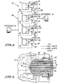
- Fig. 1 shows schematically a dual hot runner system S which accommodates two thermoplastic resins each having different optimum processing temperatures.
- One resin is provided from a source identified as extruder A and the other resin is provided from a source labeled extruder B.
- the legend of Fig. 1 indicates that the portion of the hot runner system connected to extruder A (solid lines) is maintained by suitable heaters in well-known fashion at a temperature ranging from 500 to 550°F, the optimum processing temperature for a thermoplastic resin such as PET. While the portion of the system connected to extruder B (dashed lines) is maintained at a temperature ranging from 400 to 440°F, the optimum processing temperature for a thermoplastic resin such as EVOH. It is to be noted that the resin selected and their optimum processing temperatures are merely exemplary of the present invention and their use in the present description is not intended to limit the invention to PET or to EVOH.
- the reference numerals 11, 12, 13 and 14 designate four mold cavities each communicating with individual coinjection nozzles 16, 17, 18 and 19.
- Extruder A supplies a heated manifold M which, in turn, communicates with each nozzle via hot runners or channels 21, 22, 23 and 24, respectively.
- the reference numerals 26, 27, 28 and 29 designate spool valves which operate to control charging of shooting pots or injection cylinders 31, 32, 33 and 34.
- hot manifold M b leads from extruder B to each nozzle 16, 17, 18 and 19 via hot runners or channels 36, 37, 38 and 39.
- Spool valves 41, 42, 43 and 44 control charging of shooting pots 46, 47, 48 and 49.
- Fig. 1 shows a hot runner system leading from two sources (extruders A and B) transporting conditioned thermoplastic resins to a four cavity mold, it is entirely within the scope and capability of the present invention to service as many as 16 to 48 cavities with resins originating from two or more sources.
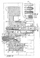
- Fig. 2 is a section of the hot runner system in the immediate vicinity of any one of the four nozzle-cavity assemblies of Fig. 1, i.e. cavity 11 and nozzle 16, for example.
- Spool valve or rotary valve 56 in circuit with channel 54 and operated (rotated) by link mechanism 57, controls the charging of reservoir 58 of the shooting pot or injection cylinder 59 equipped with an injection piston or charging piston 61.
- the spool valve 56 is formed with a transverse throughbore 62 and is shown in Fig. 2 in the closed position.
- the reservoir 58 communicates with channel 63 which leads to the nozzle assembly indicated generally by the reference numeral 64.
- Heating elements 52-52 maintain the desired processing temperature of channel 63.
- Heat conducted from manifold block 51 to a central portion of the nozzle assembly 64 maintains the integrity of the desired temperature range within the nozzle in a manner which will be described in more detail hereinafter.
- a manifold segment 65 secured to manifold block 51 is heated by elements 66-66 to maintain optimum temperature (400 to 440°F) in the hot runner connecting extruder B (not shown in Fig. 2) to channel 67 leading to the reservoir 68 of a second shooting pot 69 equipped with an injection or charging piston 71.
- a spool valve 72 (shown in Fig. 2 in the closed position relative to channel 67) controls charging of the reservoir 68.
- the reservoir 68 communicates with the nozzle assembly 64 via channel 70 by virtue of cut-out 75.
- Link mechanism 80 operates to rotate valve 72.
- nozzle assembly 64 includes a central spigot 73 in thermal contact with manifold block 51 immediately adjacent local heating elements 52-52 as is most apparent in Fig. 2.
- the spigot 73 fabricated preferably of a good metallic thermal conductor such as beryllium copper, is formed with a through channel 74 through which PET flows to the nozzle gate 76.
- the spigot is supported by minimal bearing surfaces 77-78 in a housing 79 which is spaced from the spigot substantially throughout its length by an insulating air gap 81.
- This air gap blocks conduction of heat (500 to 550°F) from the spigot 73 to the housing 79 to preserve maintenance of the EVOH at its optimum process temperature (400 to 440°F) controlled by heating means 82 as EVOH progresses through channel 80 of the housing to gate 76.
- the hot runner system of the present invention is effective to maintain different optimum process temperatures appropriate to two different resins from the source of the resin to a nozzle gate.
- extruders A and B including their cooperating shooting pots 59 and 69 are purged. Extruders A and B are moved into operative position relative to their respective manifolds. With valve stem 83 and spool valves 56 and 72 in the open position shooting pot reservoirs 58 and 68 are charged with PET and EVOH compound, respectively.
- valve stem 83 is closed and purged resin in the mold cavity is removed.
- valve stem 83 is opened and an automatic sequence occurs as follows:
- the piston 61 is held forward (in its bottomed position 100) blocking access to reservoir 58 to prevent backflow of PET compound from channel 63 into reservoir 58.
- the piston 61 is held bottomed to block access to reservoir 58 because upon subsequent operation of piston 71 to inject EVOH, the EVOH injection pressure has a tendency to displace PET from channel 63 back into reservoir 58.
- spool valve 72 is closed to extruder B and opened to channel 70. Operation of iniection piston 71 until it bottoms at 101 discharges a measured amount of EVOH into the cavity through channel 70 and gate 76.
- the volume of the first and second shots of resin is less than the total volume of the mold cavity.
- Next channel 70 is closed by appropriate rotation of spool valve 72.
- Spool valve 56 is opened allowing the PET extruder A to complete the filling of the mold cavity and to pack the molded part while PET piston 61 remains bottomed blocking access to reservoir 58.
- This step constitutes the second shot of PET (third shot of resin) to develop a five (5) layered wall as shown schematically at T in Fig. 4.
- a five (5) layered wall structure is molded using two (2) resins.
- valve stem 83 is moved to closed position and piston 61 is freed to move.
- P ET extruder A is operated to recharge reservoir 58 of shooting pot 59 displacing piston 61 until it contacts an injection stop Sa (Fig. 2).
- the position of the stop S a controls and measures the amount of PET introduced into the reservoir 58.
- injection stop Sb (Fig. 2) controls and measures the amount of EVOH introduced into the EVOH reservoir 68.
- the EVOH reservoir 68 is recharged by opening spool valve 72 to allow extruder B to displace EVOH piston 71 until the piston contacts its iniection stop Sb thus charging EVOH reservoir 68 with a measured amount of EVOH compound.
- the mold After a suitable cooling interval, the mold is opened and the article is ejected by known means.
- the above cycle is then repeated to generate additional layered articles or preforms in continuous, automatic fashion.
Abstract
Description
- The present invention relates to coinjection and relates in particular to an improved method and apparatus for molding hollow articles and preforms having a layered wall structure where the starting materials have substantially different optimum processing temperatures.
- The simultaneous or sequential injection (coinjection) of two or more resins into a mold cavity to develop layered wall structures is well known as evidenced by the disclosures of U.S. Patents Nos. 4,497,621, 4,518,344, 4,525,134 and 4,526,821, all assigned to The American Can Company.
- These disclosures, while providing separate flow paths for the respective resins, do not show or suggest a method for maintaining each resin at its optimum processing temperature during transit from an extruder or other source to the mold cavity.
- The maintenance of processing temperatures of each individual resin is especially important when the optimum processing temperature of one resin causes degradation of a second resin or vice versa.
- For example, it is frequently desirable to mold a layered wall structure for a hollow article or a preform where coinjected materials include ethylene vinyl alcohol copolymer (EVOH) which processes most satisfactorily at temperatures ranging from 400 to 440°F and polyethylene terephthalate (PET) which processes best at temperatures ranging from 500 to 550°F. As stated previously, failure to maintain these optimum temperatures individually leads to degradation of one resin or the other resulting in defective product.
- In prior art machines and processes numerous procedures have been devised to minimize the deleterious effect arising from resins having wide ranging and different processing temperatures.
- Some procedures involve attempting to process the resins very quickly minimizing residence time and thus minimizing degradation.
- Other procedures involve the use of resins that process at generally the same temperature range. Obviously, such a procedure limits the choice of resins and precludes their selection based upon desired barrier or other physical properties.
- While the above coinjection methods and procedures are operable, it is highly desirable to enhance commercial success to provide coinjection molding machines and processes in which there is complete freedom to choose resin materials on the basis of their barrier characteristics even though the chosen resins process at different temperatures.
- Consequently, it is a prime feature of the present invention to provide individual hot runner systems for each resin, from the resin source to the mold cavity, maintained and controlled independently at the temperature which is optimum for processing the selected resin.
- It is a further feature of the invention to provide a nozzle structure so constructed and arranged as to provide channels individual to each resin with individual heating means for maintaining each channel at a temperature which is most satisfactory for the resin progressing through the channel.
- A further feature of the present invention is to provide a coinjection method and apparatus which lends itself ideally to molds having a large number of cavities, i.e. 16 and 32 cavity molds, for example.
- A still further feature of the invention is the provision of "shooting pots" or injection cylinders individual to each resin channel.
- A further feature of the invention is the provision of a spool valve or rotary valve which is mechanically actuated to control positively the loading of the shooting pots and to eliminate undesirable backflow in the hot runner system.
- A further feature of the invention is the provision of a shooting pot and a cooperating spool valve assembly for each resin channel.
- A method of molding layers of different thermoplastic material sequentially where each material requires a different processing temperature according to basic principles of the present invention-may comprise the steps of providing individual sources of different thermoplastic materials each properly and individually conditioned for processing, providing a mold cavity, providing a hot runner system including conduits individual to each material leading from each source to the mold cavity and maintaining each material at the appropriate process temperature from its source to the mold cavity.
- A coinjection molding apparatus illustrating certain other principles of the invention may comprise at least one mold cavity said cavity having a nozzle individual thereto, a hot runner system including conduit means for supplying at least two thermoplastic materials to said nozzle through individual channels, each material originating from a separate source and each material having different processing temperatures and heating means associated with the molding apparatus for maintaining each material at its appropriate temperature from its source through the hot runner system and through the nozzle to the mating mold cavity.
- A nozzle structure embracing additional principles of the invention may comprise a gate for controlling admission of molding compound to an adjacent mold cavity, a plurality of independent channels within the nozzle each communicating with the gate, means for thermally insulating said channels from one another and heating means for maintaining said channels at different temperatures whereby thermoplastic resins of different optimum processing temperatures may be advanced without degradation.
- Other features and advantages of the present invention will become more apparent from an 'examination of the succeeding specification when read in conjunction with the appending drawings, in which:
-
- Fig. 1 is a schematic illustration of a hot runner system for a four cavity mold accommodating two thermoplastic resins each having different optimum processing temperatures and each maintained at its optimum temperature from its source through the coinjection nozzle,
- Fig. 2 is a sectional view illustrating details of a hot runner-nozzle assembly individual to each mold cavity of Fig. 1,
- Fig. 3 is a sectional view showing details of the nozzle of Fig. 2, inverted, and
- Fig. 4 is a series of sectional views of a molded article detailing the layered wall structure after the first, second, and third shots of resin.
- Referring now in detail to the drawings, the illustration of Fig. 1 shows schematically a dual hot runner system S which accommodates two thermoplastic resins each having different optimum processing temperatures. One resin is provided from a source identified as extruder A and the other resin is provided from a source labeled extruder B.
- While the present exemplary embodiment of the invention discloses two resin sources A and B, it is entirely within the spirit and scope of the invention to utilize more than two resin sources.
- The portion of the hot runner system leading from extruder A is shown in solid lines and that portion of the system originating with extruder B is shown in dashed lines.
- For purposes of convenient explanation of the invention, the legend of Fig. 1 indicates that the portion of the hot runner system connected to extruder A (solid lines) is maintained by suitable heaters in well-known fashion at a temperature ranging from 500 to 550°F, the optimum processing temperature for a thermoplastic resin such as PET. While the portion of the system connected to extruder B (dashed lines) is maintained at a temperature ranging from 400 to 440°F, the optimum processing temperature for a thermoplastic resin such as EVOH. It is to be noted that the resin selected and their optimum processing temperatures are merely exemplary of the present invention and their use in the present description is not intended to limit the invention to PET or to EVOH.
- Referring further to Fig. 1, the
reference numerals individual coinjection nozzles - Extruder A supplies a heated manifold M which, in turn, communicates with each nozzle via hot runners or
channels reference numerals injection cylinders - Correspondingly, hot manifold Mb leads from extruder B to each
nozzle channels Spool valves shooting pots - While the schematic of Fig. 1 shows a hot runner system leading from two sources (extruders A and B) transporting conditioned thermoplastic resins to a four cavity mold, it is entirely within the scope and capability of the present invention to service as many as 16 to 48 cavities with resins originating from two or more sources.
- Fig. 2 is a section of the hot runner system in the immediate vicinity of any one of the four nozzle-cavity assemblies of Fig. 1, i.e. cavity 11 and
nozzle 16, for example. - A
central manifold block 51 maintained at an operating temperature ranging from 500 to 550°F by heating elements 52-52 receives plasticized resin from extruder A throughchannels 53 and.54. Spool valve orrotary valve 56, in circuit withchannel 54 and operated (rotated) bylink mechanism 57, controls the charging ofreservoir 58 of the shooting pot orinjection cylinder 59 equipped with an injection piston orcharging piston 61. Thespool valve 56 is formed with atransverse throughbore 62 and is shown in Fig. 2 in the closed position. Thereservoir 58 communicates withchannel 63 which leads to the nozzle assembly indicated generally by thereference numeral 64. - Heating elements 52-52 maintain the desired processing temperature of
channel 63. - Heat conducted from
manifold block 51 to a central portion of thenozzle assembly 64 maintains the integrity of the desired temperature range within the nozzle in a manner which will be described in more detail hereinafter. - A
manifold segment 65 secured tomanifold block 51 is heated by elements 66-66 to maintain optimum temperature (400 to 440°F) in the hot runner connecting extruder B (not shown in Fig. 2) tochannel 67 leading to thereservoir 68 of asecond shooting pot 69 equipped with an injection orcharging piston 71. - Here again, a spool valve 72 (shown in Fig. 2 in the closed position relative to channel 67) controls charging of the
reservoir 68. In the closed position of thespool valve 72, thereservoir 68 communicates with thenozzle assembly 64 viachannel 70 by virtue of cut-out 75. When thespool valve 72 is open thechannel 70 is closed.Link mechanism 80 operates to rotatevalve 72. - Referring to Fig. 3 (inverted relative to the position of the nozzle in Fig. 2), note that the
nozzle assembly 64 includes acentral spigot 73 in thermal contact withmanifold block 51 immediately adjacent local heating elements 52-52 as is most apparent in Fig. 2. - The
spigot 73, fabricated preferably of a good metallic thermal conductor such as beryllium copper, is formed with a throughchannel 74 through which PET flows to thenozzle gate 76. - The spigot is supported by minimal bearing surfaces 77-78 in a
housing 79 which is spaced from the spigot substantially throughout its length by aninsulating air gap 81. This air gap blocks conduction of heat (500 to 550°F) from thespigot 73 to thehousing 79 to preserve maintenance of the EVOH at its optimum process temperature (400 to 440°F) controlled by heating means 82 as EVOH progresses throughchannel 80 of the housing togate 76. - Thus, it is apparent that the hot runner system of the present invention is effective to maintain different optimum process temperatures appropriate to two different resins from the source of the resin to a nozzle gate.
- A preferred method of operation will now be described.
- To prime the hot runner system initially, extruders A and B including their cooperating
shooting pots valve stem 83 andspool valves shooting pot reservoirs - Next valve stem 83 is closed and purged resin in the mold cavity is removed.
- Thereafter the mold is closed and clamped, valve stem 83 is opened and an automatic sequence occurs as follows:
-
Spool valve 56 is closed andinjection piston 61 is advanced until it bottoms at the point indicated by the reference numeral 100 discharging a measured amount of PET into the mold cavity throughchannel 63 andgate 76. - This constitutes the first shot of PET into the mold cavity as shown schematically at F in Fig. 4.
- The
piston 61 is held forward (in its bottomed position 100) blocking access toreservoir 58 to prevent backflow of PET compound fromchannel 63 intoreservoir 58. - That is, the
piston 61 is held bottomed to block access toreservoir 58 because upon subsequent operation ofpiston 71 to inject EVOH, the EVOH injection pressure has a tendency to displace PET fromchannel 63 back intoreservoir 58. -
Next spool valve 72 is closed to extruder B and opened to channel 70. Operation ofiniection piston 71 until it bottoms at 101 discharges a measured amount of EVOH into the cavity throughchannel 70 andgate 76. - This constitutes the first shot of EVOH into the mold cavity (second shot of resin) to develop a three (3) layered wall as shown schematically at S in Fig. 4. The volume of the first and second shots of resin is less than the total volume of the mold cavity.
-
Next channel 70 is closed by appropriate rotation ofspool valve 72.Spool valve 56 is opened allowing the PET extruder A to complete the filling of the mold cavity and to pack the molded part whilePET piston 61 remains bottomed blocking access toreservoir 58. - This step constitutes the second shot of PET (third shot of resin) to develop a five (5) layered wall as shown schematically at T in Fig. 4. Thus, a five (5) layered wall structure is molded using two (2) resins.
- After packing is completed
valve stem 83 is moved to closed position andpiston 61 is freed to move. PET extruder A is operated to rechargereservoir 58 of shootingpot 59displacing piston 61 until it contacts an injection stop Sa (Fig. 2). The position of the stop Sa controls and measures the amount of PET introduced into thereservoir 58. - In similar fashion the injection stop Sb (Fig. 2) controls and measures the amount of EVOH introduced into the
EVOH reservoir 68. - During the course of packing the mold cavity (the part) the
EVOH reservoir 68 is recharged by openingspool valve 72 to allow extruder B to displaceEVOH piston 71 until the piston contacts its iniection stop Sb thus chargingEVOH reservoir 68 with a measured amount of EVOH compound. - After a suitable cooling interval, the mold is opened and the article is ejected by known means.
- The above cycle is then repeated to generate additional layered articles or preforms in continuous, automatic fashion.
- It is to be understood that the operation just described occurs simultaneously in all four
mold cavities - It is to be understood further that the invention is not limited to the illustrations described and shown herein, which are deemed to be merely illustrative of the best modes of carrying out the invention, and which are susceptible of modification of form, size, arrangement of parts and details of operation. The invention rather is intended to encompass all such modifications which are within its spirit and scope as defined by the claims.
Claims (19)
Applications Claiming Priority (2)
| Application Number | Priority Date | Filing Date | Title |
|---|---|---|---|
| US862269 | 1986-05-12 | ||
| US06/862,269 US4717324A (en) | 1986-05-12 | 1986-05-12 | Coinjection of hollow articles and preforms |
Publications (3)
| Publication Number | Publication Date |
|---|---|
| EP0246512A2 true EP0246512A2 (en) | 1987-11-25 |
| EP0246512A3 EP0246512A3 (en) | 1988-11-30 |
| EP0246512B1 EP0246512B1 (en) | 1994-09-07 |
Family
ID=25338090
Family Applications (1)
| Application Number | Title | Priority Date | Filing Date |
|---|---|---|---|
| EP87106692A Expired - Lifetime EP0246512B1 (en) | 1986-05-12 | 1987-05-08 | Coinjection of hollow articles and preforms |
Country Status (8)
| Country | Link |
|---|---|
| US (1) | US4717324A (en) |
| EP (1) | EP0246512B1 (en) |
| JP (1) | JPS62268618A (en) |
| AT (1) | ATE111013T1 (en) |
| AU (2) | AU579768B2 (en) |
| BR (1) | BR8702360A (en) |
| CA (1) | CA1291610C (en) |
| DE (1) | DE3750489T2 (en) |
Cited By (9)
| Publication number | Priority date | Publication date | Assignee | Title |
|---|---|---|---|---|
| EP0325440A2 (en) * | 1988-01-19 | 1989-07-26 | Kamaya Kagaku Kogyo Co., Ltd. | Method and apparatus for the manufacture of three-layered containers |
| FR2631883A1 (en) * | 1988-05-27 | 1989-12-01 | Neiman Sa | METHOD AND DEVICE FOR INJECTING AT LEAST TWO MATERIALS CONSTITUTING A REFLECTOR AND REFLECTOR THUS OBTAINED |
| DE4103318A1 (en) * | 1990-02-05 | 1991-08-29 | Japan Steel Works Ltd | SPRAY HEAD |
| EP0467274A2 (en) * | 1990-07-16 | 1992-01-22 | Nissei Asb Machine Co., Ltd. | Multi-ply molding hot-runner mold |
| EP0755763A1 (en) * | 1994-03-28 | 1997-01-29 | Sumitomo Chemical Company Limited | Method of manufacturing multi-layered moldings |
| AT2516U1 (en) * | 1997-07-30 | 1998-12-28 | Engel Gmbh Maschbau | INJECTION MOLDING PROCESS |
| EP1765568A1 (en) * | 2004-07-01 | 2007-03-28 | Husky Injection Molding Systems Ltd. | Hot runner coinjection nozzle with thermally separated melt channels |
| WO2017099721A1 (en) * | 2015-12-08 | 2017-06-15 | iMFLUX Inc. | Co-injection with continuous injection molding |
| US9937647B2 (en) | 2015-12-08 | 2018-04-10 | iMFLUX Inc. | Co-injection with continuous injection molding |
Families Citing this family (85)
| Publication number | Priority date | Publication date | Assignee | Title |
|---|---|---|---|---|
| US4808101A (en) * | 1986-05-12 | 1989-02-28 | Husky Injection Molding Systems Ltd. | Tri-injection of hollow articles |
| GB8616460D0 (en) * | 1986-07-05 | 1986-08-13 | Metal Box Plc | Manufacture of articles |
| US4950143A (en) * | 1989-01-03 | 1990-08-21 | Continental Pet Technologies, Inc. | Injection mold manifold arrangement |
| CA1292848C (en) * | 1989-02-14 | 1991-12-10 | Jobst Ulrich Gellert | Injection molding system having a valve member with a ribbed insulative portion |
| US4966545A (en) * | 1989-04-19 | 1990-10-30 | Husky Injection Molding Systems Ltd. | Staged shooting pot for injection molding |
| US5192555A (en) * | 1990-02-16 | 1993-03-09 | Husky Injection Molding Systems Ltd. | Apparatus for molding plastic articles |
| US5260012A (en) * | 1990-02-16 | 1993-11-09 | Husky Injection Molding Systems Ltd. | Molding plastic articles |
| US5069840A (en) * | 1990-02-16 | 1991-12-03 | Husky Injection Molding Systems Ltd. | Molding plastic articles |
| CA2032294A1 (en) * | 1990-12-17 | 1992-06-18 | Jobst Ulrich Gellert | Thermal valve gated injection molding apparatus with melt distribution plate |
| DE4111229A1 (en) * | 1991-04-08 | 1992-10-15 | Wilhelm Hegler | DEVICE FOR PRODUCING PLASTIC TUBES |
| JP2667594B2 (en) * | 1991-04-15 | 1997-10-27 | 株式会社日本製鋼所 | Injection molding method and injection molding die |
| US5143733A (en) * | 1991-04-19 | 1992-09-01 | Husky Injection Molding Systems Ltd. | Injection molding apparatus |
| US5112212A (en) * | 1991-05-02 | 1992-05-12 | Husky Injection Molding Systems Ltd. | Shooting pot with combined valve and piston |
| US5785216A (en) * | 1991-05-29 | 1998-07-28 | Spotless Plastics Pty. Ltd. | Method of molding hangers and apparatus for implementing method |
| US5200207A (en) * | 1991-06-10 | 1993-04-06 | Husky Injection Molding Systems Ltd. | Hot runner system for coinjection |
| US5814252A (en) * | 1991-10-17 | 1998-09-29 | Spotless Plastics Pty. Ltd. | Method of molding coinjected plastic garment hangers |
| US5474735A (en) * | 1993-09-24 | 1995-12-12 | Continental Pet Technologies, Inc. | Pulse blow method for forming container with enhanced thermal stability |
| DK0688652T3 (en) * | 1994-06-06 | 2000-10-23 | Husky Injection Molding | Injection molding method with opposite inlet |
| US5650178A (en) * | 1994-11-23 | 1997-07-22 | Bemis Manufacturing Company | Co-injection manifold for injection molding |
| EE9700238A (en) * | 1995-04-19 | 1998-04-15 | Capitol Vial, Inc. | Desiccant added to a closed container |
| US5601773A (en) * | 1995-05-12 | 1997-02-11 | Cincinnati Milacron Inc. | Co-injection machine |
| US5596990A (en) * | 1995-06-06 | 1997-01-28 | Yock; Paul | Rotational correlation of intravascular ultrasound image with guide catheter position |
| TW309465B (en) * | 1995-07-05 | 1997-07-01 | Eastman Chem Co | |
| US5662856A (en) * | 1995-07-12 | 1997-09-02 | Imesco, Inc. | Low-pressure method for the preparation of hollow plastic articles |
| DE19640662C1 (en) * | 1996-10-02 | 1998-03-05 | Krupp Ag Hoesch Krupp | Injection moulding of bottle preforms |
| US5792397A (en) * | 1996-10-08 | 1998-08-11 | Ritchey; Eugene B. | Method of injection molding |
| US5840228A (en) * | 1996-10-08 | 1998-11-24 | Ritchey; Eugene B. | Method of creating indicia on a molded article |
| US6056536A (en) * | 1997-03-20 | 2000-05-02 | Husky Injection Molding Systems Ltd. | Valve gating apparatus for injection molding |
| US6464909B1 (en) * | 1998-04-21 | 2002-10-15 | Synventive Molding Solutions, Inc. | Manifold system having flow control |
| US6062840A (en) * | 1997-09-02 | 2000-05-16 | Dynisco Hotrunners, Inc. | Hot runner system for coinjection molding |
| US5858420A (en) * | 1997-08-13 | 1999-01-12 | Husky Injection Molding Systems Ltd. | Flow regulating and distributing assembly |
| US6267929B1 (en) | 1997-09-16 | 2001-07-31 | BIO MéRIEUX, INC. | Textured surface for test sample cards |
| US5972258A (en) * | 1997-10-20 | 1999-10-26 | Husky Injection Molding Systems Ltd. | Method of using a multiple gating nozzle |
| CA2219247C (en) * | 1997-10-23 | 2006-12-05 | Mold-Masters Limited | Injection molding apparatus having a melt bore through the front end of the pin |
| CA2219257C (en) * | 1997-10-23 | 2005-05-31 | Mold-Masters Limited | Sprue gated five layer injection molding apparatus |
| CA2265420C (en) | 1998-03-19 | 2005-02-08 | Husky Injection Molding Systems Ltd. | Method and system for reducing polymer degradation products in two stage injection molding machines |
| US6152721A (en) * | 1998-03-30 | 2000-11-28 | Husky Injection Molding Systems Ltd. | Shooting pot actuator for an injection molding machine |
| US7234929B2 (en) * | 1999-09-21 | 2007-06-26 | Synventive Molding Solutions, Inc. | Injection molding flow control apparatus and method |
| US6524089B1 (en) * | 1998-05-29 | 2003-02-25 | Pechiney Emballage Flexible Europe | Multilayer injection nozzle assembly |
| CA2253042C (en) * | 1998-11-05 | 2007-04-17 | Jobst Ulrich Gellert | Method of three layer injection molding with sequential and simultaneous coinjection |
| US6655945B1 (en) | 1999-03-18 | 2003-12-02 | Mold Masters Limited | Apparatus and method for multi-layer injection molding |
| US6440350B1 (en) | 1999-03-18 | 2002-08-27 | Mold-Masters Limited | Apparatus and method for multi-layer injection molding |
| US6398537B2 (en) | 1999-04-02 | 2002-06-04 | Mold-Masters Limited | Shuttle system for an apparatus for injection molding |
| US6196826B1 (en) | 1999-05-28 | 2001-03-06 | Mold-Masters Limited | Seepage system for an injection molding apparatus |
| US6276916B1 (en) | 1999-06-30 | 2001-08-21 | Husky Injection Molding Systems Ltd. | Failsafe shooting pot actuator for an injection molding machine |
| US6428727B1 (en) * | 2000-02-17 | 2002-08-06 | The Elizabeth And Sandor Valyi Foundation, Inc. | Process and apparatus for preparing a molded article |
| AU2001241822A1 (en) * | 2000-02-29 | 2001-09-12 | Bemis Manufacturing Company | No nozzle member co-injection apparatus |
| JP2001260179A (en) * | 2000-03-14 | 2001-09-25 | Aoki Technical Laboratory Inc | Hot runner mold for injection molding of multilayered preform |
| DE10055691B4 (en) * | 2000-11-06 | 2004-02-19 | Demag Ergotech Gmbh | injection molder |
| CA2364050A1 (en) * | 2000-11-30 | 2002-05-30 | Bemis Manufacturing Company | Co-injection methods using endothermic-blowing agents and products made therefrom |
| US6884061B2 (en) * | 2002-09-18 | 2005-04-26 | Mold-Masters Limited | Metering device for a nozzle of an injection molding apparatus |
| ATE376488T1 (en) * | 2002-12-03 | 2007-11-15 | Mold Masters Ltd | HOT RUNNER COINJECTION NOZZLE |
| JP4658485B2 (en) * | 2003-02-13 | 2011-03-23 | モールド−マスターズ (2007) リミテッド | Valve gate type injection molding system with independent flow control |
| EP1452293A1 (en) * | 2003-02-25 | 2004-09-01 | Mold-Masters Limited | Injection molding system with flow control and method of injection molding |
| US7125246B2 (en) * | 2003-10-08 | 2006-10-24 | Mold Hotrunner Solutions Inc. | Hot runner for molding small plastic articles |
| WO2005107988A1 (en) * | 2004-04-09 | 2005-11-17 | Bemis Manufacturing Company | One-piece co-injection housing for a co-injection apparatus |
| JP2005343099A (en) * | 2004-06-07 | 2005-12-15 | Nippon Parison Kk | Mold for preform of multilayer container |
| US20060003038A1 (en) * | 2004-06-30 | 2006-01-05 | Serniuck Nicholas W | Injection molding machine shooting pot with integral check valve |
| US7156634B2 (en) * | 2004-06-30 | 2007-01-02 | Husky Injection Molding Systems Ltd. | Injection molding machine spigotted shooting pot piston |
| US7510387B2 (en) * | 2004-06-30 | 2009-03-31 | Husky Injection Molding Systems Ltd. | Control system for dynamic feed coinjection process |
| US7165968B2 (en) * | 2004-06-30 | 2007-01-23 | Husky Injection Molding Systems Ltd. | Apparatus and method for sealing injection unit and sprue |
| US7559756B2 (en) * | 2004-06-30 | 2009-07-14 | Husky Injection Molding Systems, Ltd. | Apparatus and method for actuation of injection molding shooting pots |
| US7291304B2 (en) * | 2004-07-01 | 2007-11-06 | Husky Injection Molding Systems Ltd. | Coinjection molding cooled shooting pot cylinder |
| US7399442B2 (en) * | 2004-07-07 | 2008-07-15 | Kortec, Inc. | Multilayer molding using temperature adjustment of flow rate in conjunction with shooting pot technology |
| US7291298B2 (en) * | 2004-07-09 | 2007-11-06 | Husky Injection Molding Systems Ltd. | Apparatus and method for injection molding shooting pot wedge feature |
| CN101072820B (en) * | 2004-12-06 | 2013-01-02 | 伊士曼化工公司 | Polyester based cobalt concentrates for oxygen scavenging compositions |
| US7458805B2 (en) * | 2005-01-13 | 2008-12-02 | Axium Inc. | Gripping and positioning tool for molding machine |
| US7390184B2 (en) * | 2005-11-09 | 2008-06-24 | Centoco Plastics Limited | Dual injection manifold |
| US7458795B2 (en) * | 2006-02-24 | 2008-12-02 | Incoe Corporation | Co-injection nozzle assembly |
| US7588434B2 (en) * | 2006-08-15 | 2009-09-15 | Husky Injection Molding Systems Ltd. | Fluid distributor and translatable drive apparatus for a molding |
| US20080093772A1 (en) * | 2006-10-06 | 2008-04-24 | Graham Packing Company, Lp | Method and apparatus for delivering sequential shots to multiple cavities to form multilayer articles |
| ES2545462T3 (en) | 2008-07-21 | 2015-09-11 | Becton Dickinson And Company | Density phase separation device |
| AU2009274096B2 (en) | 2008-07-21 | 2012-08-02 | Becton, Dickinson And Company | Density phase separation device |
| CN102149472B (en) | 2008-07-21 | 2014-08-13 | 贝克顿·迪金森公司 | Density phase separation device |
| CA2949850C (en) | 2009-05-15 | 2018-03-13 | Becton, Dickinson And Company | Density phase separation device |
| CA2782963C (en) | 2009-12-31 | 2015-03-24 | Husky Injection Molding Systems Ltd. | Mold-runner system having independently controllable shooting-pot assemblies |
| JP2013519377A (en) | 2010-02-12 | 2013-05-30 | ダウ グローバル テクノロジーズ エルエルシー | Self-assembling polymer membranes for food packaging applications |
| GB2478732B (en) | 2010-03-15 | 2014-08-20 | Kraft Foods R & D Inc | Improvements in injection moulding |
| WO2012037682A2 (en) * | 2010-09-21 | 2012-03-29 | Mold-Masters (2007) Limited | Coinjection hot runner injection molding system |
| WO2013191996A2 (en) * | 2012-06-21 | 2013-12-27 | Husky Injection Molding Systems Ltd. | Shooting pot circuit valve |
| US9694359B2 (en) | 2014-11-13 | 2017-07-04 | Becton, Dickinson And Company | Mechanical separator for a biological fluid |
| US11298861B2 (en) | 2017-11-21 | 2022-04-12 | Silgan Specialty Packaging Llc | Multi-layer injection molded container |
| TWI676754B (en) * | 2018-08-28 | 2019-11-11 | 歐特捷實業股份有限公司 | valve |
| CN110886855A (en) * | 2018-09-07 | 2020-03-17 | 欧特捷实业股份有限公司 | Valve with a valve body |
| WO2021127776A1 (en) * | 2019-12-23 | 2021-07-01 | Husky Injection Molding Systems Ltd. | Injection molding of multilayer articles with post-pullback pressure monitoring |
Citations (5)
| Publication number | Priority date | Publication date | Assignee | Title |
|---|---|---|---|---|
| DE2609855A1 (en) * | 1976-03-10 | 1977-09-15 | Ver Foerderung Inst Kunststoff | Injection moulding sandwich construction mouldings - with core and skin streams separately regulated before combining at injection nozzle |
| US4124308A (en) * | 1977-06-21 | 1978-11-07 | Beloit Corporation | Sequential co-injection unit adapted for structural foam molding |
| WO1981000231A1 (en) * | 1979-07-20 | 1981-02-05 | American Can Co | Apparatus for making a multi-layer injection blow molded container |
| JPS60174622A (en) * | 1984-02-20 | 1985-09-07 | Matsushita Electric Works Ltd | Sandwich molding device |
| EP0180191A1 (en) * | 1984-10-31 | 1986-05-07 | Mitsubishi Gas Chemical Company, Inc. | Multilayered container |
Family Cites Families (13)
| Publication number | Priority date | Publication date | Assignee | Title |
|---|---|---|---|---|
| JPS5759616B2 (en) * | 1974-01-16 | 1982-12-15 | Hitachi Ltd | |
| US3981650A (en) * | 1975-01-16 | 1976-09-21 | Beloit Corporation | Melt blowing intermixed filaments of two different polymers |
| DE2507727A1 (en) * | 1975-02-22 | 1976-09-02 | Bayer Ag | DEVICE FOR DOSING AND MIXING OF FLOWABLE REACTION COMPONENTS |
| NL7512948A (en) * | 1975-11-05 | 1977-05-09 | Herstal Sa | DEVICE FOR THE MANUFACTURE OF HOLLOW PLASTIC BODIES, AND HOLLOW BODIES MADE WITH THIS DEVICE. |
| US4525134A (en) * | 1979-07-20 | 1985-06-25 | American Can Company | Apparatus for making a multi-layer injection blow molded container |
| JPS6227377Y2 (en) * | 1980-09-29 | 1987-07-14 | ||
| US4389358A (en) * | 1981-06-22 | 1983-06-21 | Kmmco Structural Foam, Inc. | Method and apparatus for making an integral structural cellular and non-cellular plastic or resinous article with a smooth outer surface |
| JPS5874332A (en) * | 1981-10-30 | 1983-05-04 | Sei Tsutsumi | Method and device for injection molding of synthetic resin |
| US4609516A (en) * | 1984-02-17 | 1986-09-02 | Continental Pet Technologies, Inc. | Method of forming laminated preforms |
| US4563149A (en) * | 1984-04-20 | 1986-01-07 | Landis Plastics Inc. | Injection molding apparatus |
| JPS60179418U (en) * | 1984-05-09 | 1985-11-28 | 日精エー・エス・ビー機械株式会社 | Hot runner mold for three-layer molding |
| DE3568525D1 (en) * | 1984-05-31 | 1989-04-06 | Toyota Motor Co Ltd | Device for tightening a coil on a cylindrical body |
| US4701292A (en) * | 1984-09-13 | 1987-10-20 | Husky Injection Molding Systems Ltd. | Method for pressure molding objects of different resins |
-
1986
- 1986-05-12 US US06/862,269 patent/US4717324A/en not_active Expired - Lifetime
-
1987
- 1987-05-08 EP EP87106692A patent/EP0246512B1/en not_active Expired - Lifetime
- 1987-05-08 AT AT87106692T patent/ATE111013T1/en not_active IP Right Cessation
- 1987-05-08 DE DE3750489T patent/DE3750489T2/en not_active Expired - Lifetime
- 1987-05-08 BR BR8702360A patent/BR8702360A/en not_active IP Right Cessation
- 1987-05-11 AU AU72688/87A patent/AU579768B2/en not_active Expired
- 1987-05-11 CA CA000536802A patent/CA1291610C/en not_active Expired - Lifetime
- 1987-05-12 JP JP62115736A patent/JPS62268618A/en active Granted
-
1989
- 1989-10-06 AU AU42603/89A patent/AU618409B2/en not_active Expired
Patent Citations (5)
| Publication number | Priority date | Publication date | Assignee | Title |
|---|---|---|---|---|
| DE2609855A1 (en) * | 1976-03-10 | 1977-09-15 | Ver Foerderung Inst Kunststoff | Injection moulding sandwich construction mouldings - with core and skin streams separately regulated before combining at injection nozzle |
| US4124308A (en) * | 1977-06-21 | 1978-11-07 | Beloit Corporation | Sequential co-injection unit adapted for structural foam molding |
| WO1981000231A1 (en) * | 1979-07-20 | 1981-02-05 | American Can Co | Apparatus for making a multi-layer injection blow molded container |
| JPS60174622A (en) * | 1984-02-20 | 1985-09-07 | Matsushita Electric Works Ltd | Sandwich molding device |
| EP0180191A1 (en) * | 1984-10-31 | 1986-05-07 | Mitsubishi Gas Chemical Company, Inc. | Multilayered container |
Non-Patent Citations (2)
| Title |
|---|
| EUROPLASTICS, vol. 46, no. 11, November 1973, pages 81-82, London, GB; "New sandwich moulding process" * |
| PATENT ABSTRACTS OF JAPAN, vol. 10, no. 14 (M-447)[2071], 21st January 1986; & JP-A-60 174 622 (MATSUSHITA DENKO K.K.) 07-09-1985 * |
Cited By (17)
| Publication number | Priority date | Publication date | Assignee | Title |
|---|---|---|---|---|
| EP0325440A2 (en) * | 1988-01-19 | 1989-07-26 | Kamaya Kagaku Kogyo Co., Ltd. | Method and apparatus for the manufacture of three-layered containers |
| EP0325440A3 (en) * | 1988-01-19 | 1990-08-29 | Kamaya Kagaku Kogyo Co., Ltd. | Three-layered containers and method and apparatus for the manufacture thereof |
| US5106284A (en) * | 1988-01-19 | 1992-04-21 | Kamaya Kagaku Kogyo Co., Ltd. | Three-layered container, a method and apparatus thereof |
| FR2631883A1 (en) * | 1988-05-27 | 1989-12-01 | Neiman Sa | METHOD AND DEVICE FOR INJECTING AT LEAST TWO MATERIALS CONSTITUTING A REFLECTOR AND REFLECTOR THUS OBTAINED |
| DE4103318A1 (en) * | 1990-02-05 | 1991-08-29 | Japan Steel Works Ltd | SPRAY HEAD |
| EP0467274A2 (en) * | 1990-07-16 | 1992-01-22 | Nissei Asb Machine Co., Ltd. | Multi-ply molding hot-runner mold |
| EP0467274A3 (en) * | 1990-07-16 | 1992-05-20 | Nissei Asb Machine Co., Ltd. | Multi-ply molding hot-runner mold |
| US5232710A (en) * | 1990-07-16 | 1993-08-03 | Nissei Asb Machine Co., Ltd. | Multi-ply molding hot-runner mold |
| EP0755763A1 (en) * | 1994-03-28 | 1997-01-29 | Sumitomo Chemical Company Limited | Method of manufacturing multi-layered moldings |
| EP0755763A4 (en) * | 1994-03-28 | 1998-07-29 | Sumitomo Chemical Co | Method of manufacturing multi-layered moldings |
| US6231798B1 (en) | 1994-03-28 | 2001-05-15 | Sumitomo Chemical Company, Ltd. | Process for producing multi-layer molded product |
| AT2516U1 (en) * | 1997-07-30 | 1998-12-28 | Engel Gmbh Maschbau | INJECTION MOLDING PROCESS |
| EP1765568A1 (en) * | 2004-07-01 | 2007-03-28 | Husky Injection Molding Systems Ltd. | Hot runner coinjection nozzle with thermally separated melt channels |
| EP1765568A4 (en) * | 2004-07-01 | 2008-12-03 | Husky Injection Molding | Hot runner coinjection nozzle with thermally separated melt channels |
| WO2017099721A1 (en) * | 2015-12-08 | 2017-06-15 | iMFLUX Inc. | Co-injection with continuous injection molding |
| US9937647B2 (en) | 2015-12-08 | 2018-04-10 | iMFLUX Inc. | Co-injection with continuous injection molding |
| US10279525B2 (en) | 2015-12-08 | 2019-05-07 | iMFLUX Inc. | System for co-injection with continuous injection molding |
Also Published As
| Publication number | Publication date |
|---|---|
| AU579768B2 (en) | 1988-12-08 |
| ATE111013T1 (en) | 1994-09-15 |
| CA1291610C (en) | 1991-11-05 |
| JPS62268618A (en) | 1987-11-21 |
| AU4260389A (en) | 1991-03-28 |
| US4717324A (en) | 1988-01-05 |
| EP0246512B1 (en) | 1994-09-07 |
| AU7268887A (en) | 1987-12-10 |
| JPH0416053B2 (en) | 1992-03-19 |
| EP0246512A3 (en) | 1988-11-30 |
| BR8702360A (en) | 1988-02-17 |
| DE3750489T2 (en) | 1995-04-27 |
| DE3750489D1 (en) | 1994-10-13 |
| AU618409B2 (en) | 1991-12-19 |
Similar Documents
| Publication | Publication Date | Title |
|---|---|---|
| US4717324A (en) | Coinjection of hollow articles and preforms | |
| US4931234A (en) | Coinjection of hollow articles and preforms | |
| US4775308A (en) | Nozzle for coinjection of hollow articles and preforms | |
| US4808101A (en) | Tri-injection of hollow articles | |
| US4863665A (en) | Tri-injection of hollow articles | |
| EP0911137B1 (en) | Multiple gating nozzle | |
| US5143733A (en) | Injection molding apparatus | |
| US5028226A (en) | Multi-cavity, co-injection molding apparatus | |
| EP1126963B1 (en) | Method of three layer injection molding with sequential and simultaneous coinjection | |
| US6491509B1 (en) | Shooting pot actuator for an injection molding machine | |
| EP0911136B1 (en) | Sprue gated five layer injection molding apparatus and method for molding five layered products | |
| EP0393389B1 (en) | Staged shooting pot for injection molding | |
| CN1215658A (en) | Injection molding apparatus having inter-manifold melt transfer bushings | |
| CA1315507C (en) | Sequential injection molding machine | |
| EP0624449A2 (en) | Method of molding plastic articles | |
| CA2462150C (en) | Multiple gating nozzle | |
| MXPA99002981A (en) | Operating container actuator for a molding machine by inyecc |
Legal Events
| Date | Code | Title | Description |
|---|---|---|---|
| PUAI | Public reference made under article 153(3) epc to a published international application that has entered the european phase |
Free format text: ORIGINAL CODE: 0009012 |
|
| AK | Designated contracting states |
Kind code of ref document: A2 Designated state(s): AT BE CH DE ES FR GB IT LI NL SE |
|
| RIN1 | Information on inventor provided before grant (corrected) |
Inventor name: BROWN, PAUL P. Inventor name: SCHAD, ROBERT D.C/O HUSKY INJECT.MOLD.SYSTEMS LTD. |
|
| PUAL | Search report despatched |
Free format text: ORIGINAL CODE: 0009013 |
|
| AK | Designated contracting states |
Kind code of ref document: A3 Designated state(s): AT BE CH DE ES FR GB IT LI NL SE |
|
| 17P | Request for examination filed |
Effective date: 19881115 |
|
| 17Q | First examination report despatched |
Effective date: 19900105 |
|
| GRAA | (expected) grant |
Free format text: ORIGINAL CODE: 0009210 |
|
| AK | Designated contracting states |
Kind code of ref document: B1 Designated state(s): AT BE CH DE ES FR GB IT LI NL SE |
|
| PG25 | Lapsed in a contracting state [announced via postgrant information from national office to epo] |
Ref country code: BE Effective date: 19940907 |
|
| REF | Corresponds to: |
Ref document number: 111013 Country of ref document: AT Date of ref document: 19940915 Kind code of ref document: T |
|
| REF | Corresponds to: |
Ref document number: 3750489 Country of ref document: DE Date of ref document: 19941013 |
|
| ITF | It: translation for a ep patent filed |
Owner name: BUGNION S.P.A. |
|
| PG25 | Lapsed in a contracting state [announced via postgrant information from national office to epo] |
Ref country code: SE Effective date: 19941207 |
|
| PG25 | Lapsed in a contracting state [announced via postgrant information from national office to epo] |
Ref country code: ES Free format text: LAPSE BECAUSE OF FAILURE TO SUBMIT A TRANSLATION OF THE DESCRIPTION OR TO PAY THE FEE WITHIN THE PRESCRIBED TIME-LIMIT Effective date: 19941218 |
|
| ET | Fr: translation filed | ||
| PLBE | No opposition filed within time limit |
Free format text: ORIGINAL CODE: 0009261 |
|
| STAA | Information on the status of an ep patent application or granted ep patent |
Free format text: STATUS: NO OPPOSITION FILED WITHIN TIME LIMIT |
|
| 26N | No opposition filed | ||
| REG | Reference to a national code |
Ref country code: GB Ref legal event code: IF02 |
|
| REG | Reference to a national code |
Ref country code: CH Ref legal event code: NV Representative=s name: BOVARD AG PATENTANWAELTE |
|
| PGFP | Annual fee paid to national office [announced via postgrant information from national office to epo] |
Ref country code: NL Payment date: 20060503 Year of fee payment: 20 Ref country code: GB Payment date: 20060503 Year of fee payment: 20 |
|
| PGFP | Annual fee paid to national office [announced via postgrant information from national office to epo] |
Ref country code: DE Payment date: 20060508 Year of fee payment: 20 |
|
| PGFP | Annual fee paid to national office [announced via postgrant information from national office to epo] |
Ref country code: AT Payment date: 20060511 Year of fee payment: 20 |
|
| PGFP | Annual fee paid to national office [announced via postgrant information from national office to epo] |
Ref country code: FR Payment date: 20060515 Year of fee payment: 20 Ref country code: CH Payment date: 20060515 Year of fee payment: 20 |
|
| PGFP | Annual fee paid to national office [announced via postgrant information from national office to epo] |
Ref country code: IT Payment date: 20060531 Year of fee payment: 20 |
|
| PG25 | Lapsed in a contracting state [announced via postgrant information from national office to epo] |
Ref country code: NL Free format text: LAPSE BECAUSE OF EXPIRATION OF PROTECTION Effective date: 20070508 |
|
| REG | Reference to a national code |
Ref country code: GB Ref legal event code: PE20 |
|
| REG | Reference to a national code |
Ref country code: CH Ref legal event code: PL |
|
| NLV7 | Nl: ceased due to reaching the maximum lifetime of a patent |
Effective date: 20070508 |
|
| PG25 | Lapsed in a contracting state [announced via postgrant information from national office to epo] |
Ref country code: GB Free format text: LAPSE BECAUSE OF EXPIRATION OF PROTECTION Effective date: 20070507 |