EP0246022A2 - Repositionable directional markers - Google Patents
Repositionable directional markers Download PDFInfo
- Publication number
- EP0246022A2 EP0246022A2 EP87304025A EP87304025A EP0246022A2 EP 0246022 A2 EP0246022 A2 EP 0246022A2 EP 87304025 A EP87304025 A EP 87304025A EP 87304025 A EP87304025 A EP 87304025A EP 0246022 A2 EP0246022 A2 EP 0246022A2
- Authority
- EP
- European Patent Office
- Prior art keywords
- markers
- directional
- elongate
- array
- portions
- Prior art date
- Legal status (The legal status is an assumption and is not a legal conclusion. Google has not performed a legal analysis and makes no representation as to the accuracy of the status listed.)
- Withdrawn
Links
Images

Classifications
-
- B—PERFORMING OPERATIONS; TRANSPORTING
- B42—BOOKBINDING; ALBUMS; FILES; SPECIAL PRINTED MATTER
- B42D—BOOKS; BOOK COVERS; LOOSE LEAVES; PRINTED MATTER CHARACTERISED BY IDENTIFICATION OR SECURITY FEATURES; PRINTED MATTER OF SPECIAL FORMAT OR STYLE NOT OTHERWISE PROVIDED FOR; DEVICES FOR USE THEREWITH AND NOT OTHERWISE PROVIDED FOR; MOVABLE-STRIP WRITING OR READING APPARATUS
- B42D9/00—Bookmarkers; Spot indicators; Devices for holding books open; Leaf turners
- B42D9/001—Devices for indicating a page in a book, e.g. bookmarkers
- B42D9/004—Devices for indicating a page in a book, e.g. bookmarkers removably attached to the book
- B42D9/005—Devices for indicating a page in a book, e.g. bookmarkers removably attached to the book clamped on the sheet
-
- B—PERFORMING OPERATIONS; TRANSPORTING
- B42—BOOKBINDING; ALBUMS; FILES; SPECIAL PRINTED MATTER
- B42F—SHEETS TEMPORARILY ATTACHED TOGETHER; FILING APPLIANCES; FILE CARDS; INDEXING
- B42F21/00—Indexing means; Indexing tabs or protectors therefor
- B42F21/06—Tabs detachably mounted on sheets, papers, cards, or suspension files
-
- Y—GENERAL TAGGING OF NEW TECHNOLOGICAL DEVELOPMENTS; GENERAL TAGGING OF CROSS-SECTIONAL TECHNOLOGIES SPANNING OVER SEVERAL SECTIONS OF THE IPC; TECHNICAL SUBJECTS COVERED BY FORMER USPC CROSS-REFERENCE ART COLLECTIONS [XRACs] AND DIGESTS
- Y10—TECHNICAL SUBJECTS COVERED BY FORMER USPC
- Y10S—TECHNICAL SUBJECTS COVERED BY FORMER USPC CROSS-REFERENCE ART COLLECTIONS [XRACs] AND DIGESTS
- Y10S206/00—Special receptacle or package
- Y10S206/813—Adhesive
-
- Y—GENERAL TAGGING OF NEW TECHNOLOGICAL DEVELOPMENTS; GENERAL TAGGING OF CROSS-SECTIONAL TECHNOLOGIES SPANNING OVER SEVERAL SECTIONS OF THE IPC; TECHNICAL SUBJECTS COVERED BY FORMER USPC CROSS-REFERENCE ART COLLECTIONS [XRACs] AND DIGESTS
- Y10—TECHNICAL SUBJECTS COVERED BY FORMER USPC
- Y10S—TECHNICAL SUBJECTS COVERED BY FORMER USPC CROSS-REFERENCE ART COLLECTIONS [XRACs] AND DIGESTS
- Y10S206/00—Special receptacle or package
- Y10S206/82—Separable, striplike plural articles
-
- Y—GENERAL TAGGING OF NEW TECHNOLOGICAL DEVELOPMENTS; GENERAL TAGGING OF CROSS-SECTIONAL TECHNOLOGIES SPANNING OVER SEVERAL SECTIONS OF THE IPC; TECHNICAL SUBJECTS COVERED BY FORMER USPC CROSS-REFERENCE ART COLLECTIONS [XRACs] AND DIGESTS
- Y10—TECHNICAL SUBJECTS COVERED BY FORMER USPC
- Y10T—TECHNICAL SUBJECTS COVERED BY FORMER US CLASSIFICATION
- Y10T428/00—Stock material or miscellaneous articles
- Y10T428/14—Layer or component removable to expose adhesive
- Y10T428/149—Sectional layer removable
- Y10T428/1495—Adhesive is on removable layer
-
- Y—GENERAL TAGGING OF NEW TECHNOLOGICAL DEVELOPMENTS; GENERAL TAGGING OF CROSS-SECTIONAL TECHNOLOGIES SPANNING OVER SEVERAL SECTIONS OF THE IPC; TECHNICAL SUBJECTS COVERED BY FORMER USPC CROSS-REFERENCE ART COLLECTIONS [XRACs] AND DIGESTS
- Y10—TECHNICAL SUBJECTS COVERED BY FORMER USPC
- Y10T—TECHNICAL SUBJECTS COVERED BY FORMER US CLASSIFICATION
- Y10T428/00—Stock material or miscellaneous articles
- Y10T428/24—Structurally defined web or sheet [e.g., overall dimension, etc.]
- Y10T428/24777—Edge feature
- Y10T428/24793—Comprising discontinuous or differential impregnation or bond
Definitions
- This invention relates to a stationery product and more particularly to repositionable, reusable directional markers which include a directional portion having low-tack, repositionable adhesive thereon and which are configured to be highly functional, economically produced and attractively dispensed.
- Rectangular repositionable notes having low-tack repositionable adhesive on a portion of the underside of the note are a very popular stationery item and have many useful applications at home, office or school.
- the low-tack repositionable adhesive enables the notes to be lifted off and repositioned on the same or another underlying object. Applying the adhesive to only a portion of the underside of the note permits the note to be conveniently grasped, lifted and repositioned by manipulating the portion of the note without the adhesive.
- Such notes typically come in a compact pad with each note releasably attached to the underlying note in the pad. However, such notes are typically rectangular in shape and do not serve to indicate direction, the sharp corners of the rectangular notes tending to catch upon other papers in the clutter and shuffle of ordinary use.
- the present invention provides a repositionable elongate directional marker having a directional portion at one end and a non-directional portion at the other end.
- Low-tack, repositionable adhesive is applied to the directional portion, while the non-directional portion is substantially free of the adhesive.
- the elongate configuration provides an appropriate space for notations.
- the end of the elongate marker including the non-directional portion is defined by a curved, regular, smooth margin, free of projecting corners which might catch on other papers.
- the preferred embodiments of the marker are further characterized by a reduced neck between the non-directional portion and the directional portion.
- the shape of the marker facilitates an efficient and inexpensive manufacturing process.
- the expensive low-tack adhesive is applied to the face stock in an elongate strip. Thereafter an array of markers are cut from the face stock so that the directional portions of the markers are cut from the portion of the face stock including the adhesive strip while the non-directional portions are cut from the face stock on either side of the adhesive strip.
- the resulting array provides an attractive and convenient configuration to market and dispense the markers.
- an exemplary embodiment of the repositionable, elongate directional marker 10 includes a directional head 12 at one end and a non-directional body 14 at the other end.
- the exemplary marker is substantially planar, having a top side and a bottom side.
- the bottom side of the head includes a low-tack repositionable adhesive 16 which enables the marker to be repeatedly released and reapplied to an object.
- the elongate shape of the marker provides an elongate, appropriately shaped, space for making notations on the top side of the marker without needlessly obscuring the underlying object. Note that the directional head of the exemplary marker directs attention along the axis 18 of the marker.
- the body of the marker is free of adhesive and accordingly may be conveniently grasped to remove the marker from its underlying object and reposition the marker on the same object or apply it to another object.
- the end of the marker incorporating the body is defined by a regular, smooth, curved margin 20 free of projecting corners which could catch on other papers and tear, remove, or disfigure the marker.
- the exemplary embodiment of FIG. 1 includes a reduced neck 21 interconnecting the head and body.
- the reduced neck is part of the curved end of the elliptically shaped body.
- the reduced neck has several purposes. It serves to set off and accentuate the directional portion of the marker thereby emphasizing the directional function of the marker. Additionally, it also provides a natural place for the marker to bend when a finger or other tool is inserted under the body of the marker preparatory to grasping and removing the marker. Bending of the marker at the neck permits the marker to remain applied to the underlying object until it is firmly grasped. Without such reduced neck the marker is liable to flip off the underlying object before the body has been securely grasped.
- FIG. 2 The design components of the exemplary marker of FIG. 1 are shown in FIG. 2. They comprise a triangle 22 and an ellipse 24.
- FIGS. 3 and 4 show further exemplary embodiments 10a amd 10b of the marker of the present invention. These exemplary embodiments are also elongate and include a directional head 12 at one end and a non-directional body 14 at the other end joined together by a reduced neck. Low-tack adhesive 16 is applied to the bottom side of the head of these markers. Note that although the body of the markers shown in FIGS. 3 and 4 is relatively longer than the body of the marker of the exemplary embodiment shown in FIG. 1, the end of the marker opposite the head is again characterized by a curved, smooth, regular margin devoid of corners.
- the present invention includes a process for efficiently and economically producing an array of markers.
- the resulting array provides an attractive and practical configuration for distributing, packaging, displaying and dispensing the markers.
- the process and the array will be explained with reference to FIGS. 5-9.
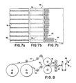
- an elongate sheet of face stock 26 is fed from a roll 28 past a gluing station 30 where low-tack, repositionable adhesive is "pattern-glued” onto one side of the face stock in a plurality of elongate adhesive strips 32, most readily seen in FIG. 7a, arranged substantially parallel to the elongate sheet of face stock.
- An elongate sheet of liner 34 is fed from a second roll 28 to a laminating station 36 where it is joined into a laminate 38 with the face stock, the adhesive strips 32 interposed between the face stock and the liner as shown in FIGS. 6 and 7b.
- the laminate is then passed to a die cutting station 40 where the face stock portion of the laminate is cut by a rotary die cutter into a plurality of arrays 42 of markers each array centered upon one of the adhesive strips.
- the die cutter does not cut the liner.
- the laminate may be preassembled into a roll of pattern-glued "pressure sensitive" paper and fed directly to the die cutting station. Another alterna tive would include printing the face stock of the laminate or of the pressure sensitive paper prior to die cutting to add a message, logo or the like to the individual markers.
- the laminate may be passed to a stripping station 44 where the excess face stock is stripped away from the laminate leaving continuous arrays 42 of markers adhering to the liner along the adhesive strips as partially shown in FIG. 7c.
- continuous arrays of markers with the excess face stock stripped away may be cut into rows, each row including one continuous array, and the rows assembled into compact rolls which may be dispersed like stamps.
- the die cut laminate may be sent to a sheeting station, not shown, where the die cut laminate is cut into sheets, strips, or cards.
- FIG. 5 shows a card 45 including an array 42 of markers, and the excess face stock 46.
- the die cutter cuts the markers in arrays of ten markers and also cuts serrated lines 48 in the face stock to facilitate removal of the excess face stock 46.
- a plurality of cards such as shown in FIG. 5 may be fastened together into a pad of cards.
- each card may be grasped by its elongate sides and squeezed so that the face of the card is convex and the bodies 14 of the markers 10 in the array stand out from the card where they may be conveniently grasped as shown in FIG. 9.
- each array 42 of markers includes an elongate row of markers having their triangular heads adjacent to one another and intermeshed on the adhesive strip, the bodies of the markers forming two rows, parallel to and on either side of the adhesive strip. It should be noted that this arrangement, with the triangular intermeshed heads pointing in the opposite direction from adjacent heads, permit all of the adhesive strip to be encompassed by the triangular heads of the markers, the intermeshed triangular heads together approximating the the adhesive strip. Since the low-tack, repositionable adhesive is relatively expensive, the process and array described above is an efficient use of the expensive glue.
- the face stock is also efficiently used by this process and array by making the bodies of the markers approximately the same width as the heads. It will be appreciated that while the bodies may be of other dimensions, bodies wider than the heads would result in waste of the expensive glue, while bodies narrower than the heads would result in waste of face stock.
Abstract
Description
- This invention relates to a stationery product and more particularly to repositionable, reusable directional markers which include a directional portion having low-tack, repositionable adhesive thereon and which are configured to be highly functional, economically produced and attractively dispensed.
- Rectangular repositionable notes having low-tack repositionable adhesive on a portion of the underside of the note are a very popular stationery item and have many useful applications at home, office or school. The low-tack repositionable adhesive enables the notes to be lifted off and repositioned on the same or another underlying object. Applying the adhesive to only a portion of the underside of the note permits the note to be conveniently grasped, lifted and repositioned by manipulating the portion of the note without the adhesive. Such notes typically come in a compact pad with each note releasably attached to the underlying note in the pad. However, such notes are typically rectangular in shape and do not serve to indicate direction, the sharp corners of the rectangular notes tending to catch upon other papers in the clutter and shuffle of ordinary use.
- The lack of repositionable directional markets is probably due to perceived problems in the production and dispensing of such markers.
- The present invention provides a repositionable elongate directional marker having a directional portion at one end and a non-directional portion at the other end. Low-tack, repositionable adhesive is applied to the directional portion, while the non-directional portion is substantially free of the adhesive. The elongate configuration provides an appropriate space for notations. The end of the elongate marker including the non-directional portion is defined by a curved, regular, smooth margin, free of projecting corners which might catch on other papers. The preferred embodiments of the marker are further characterized by a reduced neck between the non-directional portion and the directional portion.
- The shape of the marker facilitates an efficient and inexpensive manufacturing process. The expensive low-tack adhesive is applied to the face stock in an elongate strip. Thereafter an array of markers are cut from the face stock so that the directional portions of the markers are cut from the portion of the face stock including the adhesive strip while the non-directional portions are cut from the face stock on either side of the adhesive strip. The resulting array provides an attractive and convenient configuration to market and dispense the markers.
- Accordingly, it is a principal object of the present invention to provide a repositionable directional marker.
- It is a further object of the present invention to provide such a marker having a directional and non-directional portion.
- It is an associated object of the present invention to provide such a marker having a reduced neck between the directional and non-directional portions.
- It is another object of the present invention to provide such a marker having low-tack repositionable adhesive applied to the directional portion of the marker.
- It is a related object of the present invention to provide a marker adapted to receive notations thereon.
- It is an associated object of the present invention to provide a marker having a pleasing and functional shape.
- It is another object of the present invention to provide an elongate marker which has a regular curved margin on the end opposite the directional portion.
- It is a further object of the present invention to provide an inexpensive and efficient method of manufacturing the marker.
- It is a related object of the present invention to provide an array of such markers well-suited for appearance and functionality.
- The following is a specific description intended to illustrate the present invention by way of example only, reference being made to the accompanying drawings, in which:-
- FIG. 1 illustrates an exemplary marker.
- FIG. 2 shows the design components of the marker of FIG. 1.
- FIG. 3 illustrates another exemplary marker.
- FIG. 4 illustrates a further exemplary marker.
- FIG. 5 shows a card having an array of markers with their directional portions intermeshed.
- FIG. 6 is a partial cross-sectional view of the laminate including face stock, adhesive and liner.
- FIGS. 7a-c illustrate some of the steps in the process of producing the array shown in FIG. 5.
- FIG. 8 is a schematic elevation view of the manufacturing process illustrated in FIGS. 7a-c.
- FIG. 9 is an end elevation of the card of FIG. 5 which is bent into convex configuration.
- Referring to FIG. 1, an exemplary embodiment of the repositionable, elongate
directional marker 10 includes adirectional head 12 at one end and anon-directional body 14 at the other end. The exemplary marker is substantially planar, having a top side and a bottom side. The bottom side of the head includes a low-tackrepositionable adhesive 16 which enables the marker to be repeatedly released and reapplied to an object. The elongate shape of the marker provides an elongate, appropriately shaped, space for making notations on the top side of the marker without needlessly obscuring the underlying object. Note that the directional head of the exemplary marker directs attention along theaxis 18 of the marker. - The body of the marker is free of adhesive and accordingly may be conveniently grasped to remove the marker from its underlying object and reposition the marker on the same object or apply it to another object. The end of the marker incorporating the body is defined by a regular, smooth,
curved margin 20 free of projecting corners which could catch on other papers and tear, remove, or disfigure the marker. - The exemplary embodiment of FIG. 1 includes a reduced
neck 21 interconnecting the head and body. In actuality the reduced neck is part of the curved end of the elliptically shaped body. The reduced neck has several purposes. It serves to set off and accentuate the directional portion of the marker thereby emphasizing the directional function of the marker. Additionally, it also provides a natural place for the marker to bend when a finger or other tool is inserted under the body of the marker preparatory to grasping and removing the marker. Bending of the marker at the neck permits the marker to remain applied to the underlying object until it is firmly grasped. Without such reduced neck the marker is liable to flip off the underlying object before the body has been securely grasped. - The design components of the exemplary marker of FIG. 1 are shown in FIG. 2. They comprise a
triangle 22 and anellipse 24. - FIGS. 3 and 4 show further
exemplary embodiments 10a amd 10b of the marker of the present invention. These exemplary embodiments are also elongate and include adirectional head 12 at one end and anon-directional body 14 at the other end joined together by a reduced neck. Low-tack adhesive 16 is applied to the bottom side of the head of these markers. Note that although the body of the markers shown in FIGS. 3 and 4 is relatively longer than the body of the marker of the exemplary embodiment shown in FIG. 1, the end of the marker opposite the head is again characterized by a curved, smooth, regular margin devoid of corners. - The present invention includes a process for efficiently and economically producing an array of markers. The resulting array provides an attractive and practical configuration for distributing, packaging, displaying and dispensing the markers. The process and the array will be explained with reference to FIGS. 5-9.
- Referring to FIGS. 6-8, an elongate sheet of
face stock 26 is fed from aroll 28 past agluing station 30 where low-tack, repositionable adhesive is "pattern-glued" onto one side of the face stock in a plurality of elongateadhesive strips 32, most readily seen in FIG. 7a, arranged substantially parallel to the elongate sheet of face stock. An elongate sheet ofliner 34 is fed from asecond roll 28 to a laminatingstation 36 where it is joined into alaminate 38 with the face stock, theadhesive strips 32 interposed between the face stock and the liner as shown in FIGS. 6 and 7b. The laminate is then passed to adie cutting station 40 where the face stock portion of the laminate is cut by a rotary die cutter into a plurality ofarrays 42 of markers each array centered upon one of the adhesive strips. The die cutter does not cut the liner. Alternatively, the laminate may be preassembled into a roll of pattern-glued "pressure sensitive" paper and fed directly to the die cutting station. Another alterna tive would include printing the face stock of the laminate or of the pressure sensitive paper prior to die cutting to add a message, logo or the like to the individual markers. - Thereafter, the laminate may be passed to a stripping
station 44 where the excess face stock is stripped away from the laminate leavingcontinuous arrays 42 of markers adhering to the liner along the adhesive strips as partially shown in FIG. 7c. Such continuous arrays of markers with the excess face stock stripped away may be cut into rows, each row including one continuous array, and the rows assembled into compact rolls which may be dispersed like stamps. - Alternatively, the die cut laminate may be sent to a sheeting station, not shown, where the die cut laminate is cut into sheets, strips, or cards. FIG. 5 shows a
card 45 including anarray 42 of markers, and theexcess face stock 46. To create the card shown in FIG. 5, the die cutter cuts the markers in arrays of ten markers and also cutsserrated lines 48 in the face stock to facilitate removal of theexcess face stock 46. A plurality of cards such as shown in FIG. 5 may be fastened together into a pad of cards. To remove individual markers from the array, each card may be grasped by its elongate sides and squeezed so that the face of the card is convex and thebodies 14 of themarkers 10 in the array stand out from the card where they may be conveniently grasped as shown in FIG. 9. - Referring to FIGS. 5 and 7c it will be seen that each
array 42 of markers includes an elongate row of markers having their triangular heads adjacent to one another and intermeshed on the adhesive strip, the bodies of the markers forming two rows, parallel to and on either side of the adhesive strip. It should be noted that this arrangement, with the triangular intermeshed heads pointing in the opposite direction from adjacent heads, permit all of the adhesive strip to be encompassed by the triangular heads of the markers, the intermeshed triangular heads together approximating the the adhesive strip. Since the low-tack, repositionable adhesive is relatively expensive, the process and array described above is an efficient use of the expensive glue. It should also be noted that the face stock is also efficiently used by this process and array by making the bodies of the markers approximately the same width as the heads. It will be appreciated that while the bodies may be of other dimensions, bodies wider than the heads would result in waste of the expensive glue, while bodies narrower than the heads would result in waste of face stock. - The terms and expressions which have been employed in the foregoing specification are used therein as terms of description and not of limitation, and there is no intention, in the use of such terms and expressions, of excluding equivalents of the features shown and described or portions thereof.
Claims (8)
Applications Claiming Priority (2)
| Application Number | Priority Date | Filing Date | Title |
|---|---|---|---|
| US862108 | 1986-05-12 | ||
| US06/862,108 US4680210A (en) | 1986-05-12 | 1986-05-12 | Repositionable directional markers |
Publications (2)
| Publication Number | Publication Date |
|---|---|
| EP0246022A2 true EP0246022A2 (en) | 1987-11-19 |
| EP0246022A3 EP0246022A3 (en) | 1989-02-01 |
Family
ID=25337682
Family Applications (1)
| Application Number | Title | Priority Date | Filing Date |
|---|---|---|---|
| EP87304025A Withdrawn EP0246022A3 (en) | 1986-05-12 | 1987-05-05 | Repositionable directional markers |
Country Status (5)
| Country | Link |
|---|---|
| US (1) | US4680210A (en) |
| EP (1) | EP0246022A3 (en) |
| JP (1) | JPS62268691A (en) |
| AU (1) | AU7263987A (en) |
| CA (1) | CA1273789A (en) |
Cited By (2)
| Publication number | Priority date | Publication date | Assignee | Title |
|---|---|---|---|---|
| GB2280659A (en) * | 1993-08-06 | 1995-02-08 | Hannay John W & Co Ltd | Adhesive labels |
| WO2004009370A1 (en) * | 2002-07-19 | 2004-01-29 | Andres Michel Vinay Flores | Adhesive marker for printed texts and/or books |
Families Citing this family (37)
| Publication number | Priority date | Publication date | Assignee | Title |
|---|---|---|---|---|
| US4826712B1 (en) * | 1987-04-20 | 1996-09-24 | Mark H Theno | Decorative ribbons |
| US4876131A (en) * | 1988-02-09 | 1989-10-24 | Moore Business Forms, Inc. | Continuous form with releasable label |
| JPH0659752B2 (en) * | 1988-03-29 | 1994-08-10 | 三和紙業株式会社 | Adhesive sheet with film and manufacturing method thereof |
| US4863128A (en) * | 1988-05-13 | 1989-09-05 | Voxcom, Inc. | Liner reinforced hang tab |
| US5249546A (en) * | 1990-08-22 | 1993-10-05 | Pennelle Joseph F | Bookmark |
| US6129977A (en) * | 1990-09-17 | 2000-10-10 | 3M Innovative Properties Company | Tape roll structure for use in making marginal edge tabs for sheets |
| US5104148A (en) * | 1990-11-21 | 1992-04-14 | Wallace Computer Services, Inc. | Auto key ring identification tag product |
| US5101756A (en) * | 1990-12-31 | 1992-04-07 | Strumbos William P | Marker arrow system |
| US5283091A (en) * | 1991-10-07 | 1994-02-01 | Minnesota Mining And Manufacturing Company | Tape flag with transparent boundary indicating coating |
| US5306271A (en) * | 1992-03-09 | 1994-04-26 | Izi Corporation | Radiation therapy skin markers |
| DE4239764A1 (en) * | 1992-11-26 | 1994-06-01 | Pedro Rodriguez | Bookmark system consisting of bookmarks, bookmark magazine and handling procedure |
| US5332265A (en) * | 1993-01-22 | 1994-07-26 | Minnesota Mining And Manufacturing Company | Advertising assembly |
| US5468523A (en) * | 1993-03-15 | 1995-11-21 | Minnesota Mining And Manufacturing Company | Method and apparatus for forming prefabricated self-forming self-adhering pull bow and pull bow formed thereby |
| US6379764B1 (en) * | 1993-07-21 | 2002-04-30 | 3M Innovative Properties Company | Method and apparatus for placing linerless repositionable sheets directly onto advertising signatures |
| JPH09505359A (en) * | 1993-11-16 | 1997-05-27 | ミネソタ・マイニング・アンド・マニュファクチュアリング・カンパニー | Preformed self-adhesive knot structure |
| US5409753A (en) * | 1994-04-22 | 1995-04-25 | Perez; Roberto J. | Publication marker and method of using the same |
| US5782494A (en) * | 1995-12-19 | 1998-07-21 | Minnesota Mining And Manufacturing Company | Desktop printer notes |
| US6244628B1 (en) * | 1996-09-30 | 2001-06-12 | Peter D. Muller | Text tabbing system and method |
| KR20000048898A (en) * | 1996-10-04 | 2000-07-25 | 스프레이그 로버트 월터 | Tape roll structure for use in making marginal edge tabs for sheets |
| US6526906B1 (en) * | 1996-10-18 | 2003-03-04 | Edward Bidanset | Page marking device |
| US5743899A (en) * | 1997-03-04 | 1998-04-28 | Izi Medical Products | Method and apparatus for marking skin with ink |
| EP0928701A3 (en) | 1997-10-27 | 1999-10-06 | Ko-Pack International (Europe) Limited | Dispensing adhesive peelable page markers |
| DK173962B1 (en) * | 1999-05-06 | 2002-03-18 | Coloplast As | An ostomy siting device |
| AR019961A1 (en) * | 1999-07-29 | 2002-03-27 | Prinzio Nicolas Di | MAGNETIC PAGE MARKER. |
| US6257623B1 (en) * | 2000-01-18 | 2001-07-10 | Rr Donnelley & Sons | Printed publication having integrated bookmarks and method of manufacturing same |
| US7964228B2 (en) * | 2001-07-24 | 2011-06-21 | Ecolab Usa Inc. | Method for enhancing food safety |
| US7128957B2 (en) * | 2002-08-28 | 2006-10-31 | Avery Dennison Corporation | Repositionable pad of tabs |
| AU2003302606A1 (en) * | 2002-11-29 | 2004-06-23 | Donald G. Russell | Markers, methods of marking, and marking systems for use in association with images |
| US20060207144A1 (en) * | 2005-03-21 | 2006-09-21 | Daydots Holdings, Inc. | Adhesive labels and indicia for use in food rotation to enhance methods of food safety in the food industry |
| EP2138321A1 (en) * | 2007-04-04 | 2009-12-30 | Shoichi Aoki | Bookmark |
| US8307776B2 (en) * | 2007-10-25 | 2012-11-13 | Brooks Andre L | Smart bookmark |
| AU2011216036B2 (en) * | 2010-02-09 | 2014-09-25 | Avery Dennison Corporation | Healthcare form assembly having a plurality of removable strips with adhesive free feature |
| US20120082815A1 (en) * | 2010-02-09 | 2012-04-05 | Avery Dennison Corporation | Healthcare Form Assembly Having a Plurality of Removable Strips with Adhesive Free Feature |
| USD683397S1 (en) | 2010-04-21 | 2013-05-28 | Avery Dennison Corporation | Pad of labels |
| US8528731B2 (en) | 2010-04-21 | 2013-09-10 | Ccl Label, Inc. | Labels, related pads thereof, and related methods |
| US20130199437A1 (en) * | 2012-02-03 | 2013-08-08 | Gary Johnson | Booktag |
| WO2014066195A1 (en) | 2012-10-22 | 2014-05-01 | Avery Dennison Corporation | Hybrid material of crosslinked microgel particles dispersed in an adhesive |
Citations (5)
| Publication number | Priority date | Publication date | Assignee | Title |
|---|---|---|---|---|
| GB450816A (en) * | 1935-01-18 | 1936-07-24 | Isabelle Flavie Grand | Improvements in labels |
| US3481058A (en) * | 1967-07-26 | 1969-12-02 | Eng Model Associates | Identifying system |
| US3583358A (en) * | 1969-03-10 | 1971-06-08 | Leonard J Hanson Jr | Detachable marker tab and retainer therefor |
| US4188251A (en) * | 1977-01-10 | 1980-02-12 | Monarch Marking Systems, Inc. | Method of dispensing labels |
| FR2469767A1 (en) * | 1979-11-12 | 1981-05-22 | Turner James | Book marker for easy reference to bulky volumes - has pressure sensitive adhesive surface for sticking to page |
-
1986
- 1986-05-12 US US06/862,108 patent/US4680210A/en not_active Expired - Fee Related
-
1987
- 1987-05-05 CA CA000536345A patent/CA1273789A/en not_active Expired
- 1987-05-05 EP EP87304025A patent/EP0246022A3/en not_active Withdrawn
- 1987-05-08 AU AU72639/87A patent/AU7263987A/en not_active Abandoned
- 1987-05-11 JP JP62112639A patent/JPS62268691A/en active Pending
Patent Citations (5)
| Publication number | Priority date | Publication date | Assignee | Title |
|---|---|---|---|---|
| GB450816A (en) * | 1935-01-18 | 1936-07-24 | Isabelle Flavie Grand | Improvements in labels |
| US3481058A (en) * | 1967-07-26 | 1969-12-02 | Eng Model Associates | Identifying system |
| US3583358A (en) * | 1969-03-10 | 1971-06-08 | Leonard J Hanson Jr | Detachable marker tab and retainer therefor |
| US4188251A (en) * | 1977-01-10 | 1980-02-12 | Monarch Marking Systems, Inc. | Method of dispensing labels |
| FR2469767A1 (en) * | 1979-11-12 | 1981-05-22 | Turner James | Book marker for easy reference to bulky volumes - has pressure sensitive adhesive surface for sticking to page |
Cited By (2)
| Publication number | Priority date | Publication date | Assignee | Title |
|---|---|---|---|---|
| GB2280659A (en) * | 1993-08-06 | 1995-02-08 | Hannay John W & Co Ltd | Adhesive labels |
| WO2004009370A1 (en) * | 2002-07-19 | 2004-01-29 | Andres Michel Vinay Flores | Adhesive marker for printed texts and/or books |
Also Published As
| Publication number | Publication date |
|---|---|
| AU7263987A (en) | 1987-11-19 |
| JPS62268691A (en) | 1987-11-21 |
| US4680210A (en) | 1987-07-14 |
| EP0246022A3 (en) | 1989-02-01 |
| CA1273789A (en) | 1990-09-11 |
Similar Documents
| Publication | Publication Date | Title |
|---|---|---|
| US4680210A (en) | Repositionable directional markers | |
| US4586631A (en) | Dispensing package for sheets | |
| US5318825A (en) | Paper-product sheet having concealed repositionable adhesive | |
| US5587222A (en) | Label assembly with multi-ply insert | |
| JP3858082B2 (en) | Pad with co-adhesive adhesive sheet | |
| US3924744A (en) | Index tab sheet | |
| US3444635A (en) | Self-adhering index tag assembly,multiple unit thereof,and method of manufacture | |
| US4570797A (en) | Adhesive tape carrier for purse or pocket and method for making same | |
| US4525399A (en) | Perforated reinforcing strip for use with continuous forms | |
| US6511097B2 (en) | Coupon booklet and method | |
| US5970640A (en) | Integrated shelf talker and method of making same | |
| US4853268A (en) | Binding hole reinforcement, method and apparatus | |
| US6349970B2 (en) | Printed publication having integrated bookmarks and method of manufacturing same | |
| WO2002100655A1 (en) | Label pad construction | |
| JPH0327816Y2 (en) | ||
| US3055680A (en) | Book mark method and apparatus | |
| US20050019538A1 (en) | Document sheet with recessed cavity having an access tab for an object received therein | |
| US5566566A (en) | Method of making a paper clip | |
| CN2226050Y (en) | Clip for tearing adhesive tape | |
| JP3022749U (en) | Name plate sheet | |
| DE19947424A1 (en) | Dispensing device for self-adhesive functional items, in which each functional item is folded through 180 degrees | |
| JPH0681780U (en) | Adhesive tape | |
| JPH079662Y2 (en) | Books with banded paper | |
| JP3059213U (en) | Wall hook | |
| JPH081897Y2 (en) | Delivery slip continuum |
Legal Events
| Date | Code | Title | Description |
|---|---|---|---|
| PUAI | Public reference made under article 153(3) epc to a published international application that has entered the european phase |
Free format text: ORIGINAL CODE: 0009012 |
|
| AK | Designated contracting states |
Kind code of ref document: A2 Designated state(s): DE FR GB IT NL |
|
| PUAL | Search report despatched |
Free format text: ORIGINAL CODE: 0009013 |
|
| AK | Designated contracting states |
Kind code of ref document: A3 Designated state(s): DE FR GB IT NL |
|
| RHK1 | Main classification (correction) |
Ipc: G09F 3/10 |
|
| 17P | Request for examination filed |
Effective date: 19890801 |
|
| DIN1 | Information on inventor provided before grant (deleted) | ||
| RAP1 | Party data changed (applicant data changed or rights of an application transferred) |
Owner name: ZWECKFORM BUERO-PRODUKTE GMBH |
|
| RIN1 | Information on inventor provided before grant (corrected) |
Inventor name: CORCORAN, DAN E. |
|
| 17Q | First examination report despatched |
Effective date: 19910618 |
|
| STAA | Information on the status of an ep patent application or granted ep patent |
Free format text: STATUS: THE APPLICATION HAS BEEN WITHDRAWN |
|
| 18W | Application withdrawn |
Withdrawal date: 19920130 |