EP0243854B1 - Implantierbare, abgleichbare Messvorrichtung für eine Körpersubstanz - Google Patents
Implantierbare, abgleichbare Messvorrichtung für eine Körpersubstanz Download PDFInfo
- Publication number
- EP0243854B1 EP0243854B1 EP87105853A EP87105853A EP0243854B1 EP 0243854 B1 EP0243854 B1 EP 0243854B1 EP 87105853 A EP87105853 A EP 87105853A EP 87105853 A EP87105853 A EP 87105853A EP 0243854 B1 EP0243854 B1 EP 0243854B1
- Authority
- EP
- European Patent Office
- Prior art keywords
- measuring sensor
- substance
- membrane
- liquid
- measuring
- Prior art date
- Legal status (The legal status is an assumption and is not a legal conclusion. Google has not performed a legal analysis and makes no representation as to the accuracy of the status listed.)
- Expired - Lifetime
Links
Images

Classifications
-
- A—HUMAN NECESSITIES
- A61—MEDICAL OR VETERINARY SCIENCE; HYGIENE
- A61B—DIAGNOSIS; SURGERY; IDENTIFICATION
- A61B5/00—Measuring for diagnostic purposes; Identification of persons
- A61B5/145—Measuring characteristics of blood in vivo, e.g. gas concentration, pH value; Measuring characteristics of body fluids or tissues, e.g. interstitial fluid, cerebral tissue
- A61B5/1486—Measuring characteristics of blood in vivo, e.g. gas concentration, pH value; Measuring characteristics of body fluids or tissues, e.g. interstitial fluid, cerebral tissue using enzyme electrodes, e.g. with immobilised oxidase
- A61B5/14865—Measuring characteristics of blood in vivo, e.g. gas concentration, pH value; Measuring characteristics of body fluids or tissues, e.g. interstitial fluid, cerebral tissue using enzyme electrodes, e.g. with immobilised oxidase invasive, e.g. introduced into the body by a catheter or needle or using implanted sensors
-
- A—HUMAN NECESSITIES
- A61—MEDICAL OR VETERINARY SCIENCE; HYGIENE
- A61B—DIAGNOSIS; SURGERY; IDENTIFICATION
- A61B5/00—Measuring for diagnostic purposes; Identification of persons
- A61B5/145—Measuring characteristics of blood in vivo, e.g. gas concentration, pH value; Measuring characteristics of body fluids or tissues, e.g. interstitial fluid, cerebral tissue
- A61B5/14525—Measuring characteristics of blood in vivo, e.g. gas concentration, pH value; Measuring characteristics of body fluids or tissues, e.g. interstitial fluid, cerebral tissue using microdialysis
- A61B5/14528—Measuring characteristics of blood in vivo, e.g. gas concentration, pH value; Measuring characteristics of body fluids or tissues, e.g. interstitial fluid, cerebral tissue using microdialysis invasively
-
- A—HUMAN NECESSITIES
- A61—MEDICAL OR VETERINARY SCIENCE; HYGIENE
- A61B—DIAGNOSIS; SURGERY; IDENTIFICATION
- A61B5/00—Measuring for diagnostic purposes; Identification of persons
- A61B5/68—Arrangements of detecting, measuring or recording means, e.g. sensors, in relation to patient
- A61B5/6846—Arrangements of detecting, measuring or recording means, e.g. sensors, in relation to patient specially adapted to be brought in contact with an internal body part, i.e. invasive
- A61B5/6847—Arrangements of detecting, measuring or recording means, e.g. sensors, in relation to patient specially adapted to be brought in contact with an internal body part, i.e. invasive mounted on an invasive device
- A61B5/686—Permanently implanted devices, e.g. pacemakers, other stimulators, biochips
Definitions
- the invention relates to a measuring device for a body substance that can be implanted in a body, with a measuring sensor located in a housing, which has a body substance to be measured that can be extracted from the body via a first membrane as a filtrate, and also a foreign substance that is injectable from the outside via a piercing septum and a supply device which can be supplied with a calibration, rinsing or active substance.
- the control of an implanted drug dosing device ideally takes place via a likewise implanted measuring device which detects the body parameters to be controlled via a measuring sensor.
- a control signal for a metering pump is derived from the electronically processed measurement signal.
- Such a device is known for example from WO 81/01794.
- the glucose concentration in the body for example in the blood, in the connective tissue or in the peritoneum of the patient, serves as a measurement or control variable.
- the tax rate is the insulin delivery rate.
- the measuring sensor is generally subjected to a drift, which can affect both the zero point, the slope and possibly the shape of the measuring characteristic.
- An implantable measuring device of the aforementioned type is known from EP-A 0 102 548.
- the measuring sensor is connected to a body fluid directly or via an intermediate membrane which is permeable to certain body substances. In order to keep the sensor in an effective operating state, it can be withdrawn into a maintenance housing and cleaned or regenerated there.
- EP-A 0 036 171 discloses a measuring device of the type described at the outset, the measuring sensor of which is fixed in a catheter-like tube. Via a channel within this tube, a liquid of known chemical properties can be applied to the sensor in order to calibrate the sensor output signal. Only liquids that are compatible with the body can be used.
- the invention has for its object to design a measuring device of the type mentioned in such a way that its measuring sensor can remain implanted in the same place in the body of a patient for a long time without the patient supplying falsified measuring signals.
- a drift in the measurement signal of the measurement sensor should be able to be detected and compensated for using a calibration liquid.
- flushing processes to prevent or remove deposits in the measuring circuit without changing the location of the elements to be cleaned.
- the measuring sensor of the implanted measuring device can be adjusted at the required times without external intervention in the body and without having to remove the measuring sensor itself from its position in the body.
- the substance located on the measuring sensor is sucked off
- calibration substance is brought to the measuring sensor and in a third step this measuring substance is measured by the measuring sensor.
- the puncture septum and the buffer memory are connected to the measuring sensor via flow paths. The arrangement of the buffer memory from the puncture septum, viewed behind the measuring sensor, also creates the possibility of leading a calibration substance to and through the measuring sensor.
- the measuring sensor is part of its own liquid circuit, separated from the circuit of the ultrafiltrate by a semipermeable membrane, in which calibration or rinsing processes can be carried out independently of the circuit of the ultrafiltrate.
- a liquid enzyme is to be used as a foreign substance, this means that this substance can be supplied in a considerably smaller amount than would be necessary if it were supplied directly to the ultrafiltrate tract.
- the double ultrafiltration prevents the enzyme that is toxic to the body from escaping into the body's circulation.
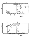
- the measuring device 1 shows a measuring device 1 which can be implanted in the body of a patient and which is used to measure or analyze a body fluid, in particular glucose in the body fluid speed is provided.
- the measuring device 1 comprises a housing 3, which is relatively flat.
- a housing surface for example an end surface of the housing 3, is provided with a large-area semipermeable membrane 5.
- the membrane 5 has an area of, for example, 20 cm 2.
- the membrane 5 is surrounded by a flat, pot-shaped capsule 7.
- a support grid 9 is arranged in the space 8 between the capsule 7 and the membrane 5.
- a connection or feed line 11 leads from the intermediate space 8, which is formed by the membrane 5 and the capsule 7, via a measuring sensor 13 to a conveying device 15, e.g. B. an electric pump P. From the conveyor 15, another line 17 leads to an outlet opening 19 in the housing 3.
- the measuring sensor 13 is followed by electronics (not shown) for processing and / or processing the measured values.
- a buffer store 25 is preferably connected to the space 8 between the membrane 5 and the capsule 7.
- the buffer store 25 can be, for example, a bellows with elastic walls, which can collapse in itself. It is also possible to form the buffer store by some other elasticity in the fluid tract, for example by the inherent elasticity of the membrane 5 or the capsule 7.
- a puncture septum 27 is connected to the feed line 11 via a connecting web 29. This creates a flow path, consisting of supply line 11, intermediate space 8 and connecting web 29, which connects the buffer memory 25, the measuring sensor 13 and the puncture septum 27 to one another in terms of lines.
- the semipermeable membrane 5 is selected so that only substances with a molecular weight below a predetermined limit value can pass as ultrafiltrate.
- the specified limit value depends on the substance to be measured or analyzed.
- the membrane 5 is dimensioned such that it is essentially permeable to molecules up to the size of glucose molecules.
- the area of the membrane 5 is chosen so large that even if the membrane 5 should be completely coated with connective tissue, an average delivery flow of the filtrate impressed by the delivery device 15 can be maintained. This is possible because the connective tissue is always supplied by the body and thus maintains a finite permeability.
- the amount of filtrate pumped out must be so small that the tissue diffusion capacity does not hinder the inflow. The influence of the permeability of the membrane 5 on the measurement signal determined by the measurement sensor 13 is thus eliminated.
- the needle or cannula of a syringe is pierced from the outside through the piercing septum 27.
- the liquid contained in the flow path is drawn off through the cannula until the buffer store 25 has collapsed.
- the syringe is then emptied outside the patient and filled with a calibration substance.
- the syringe with the calibration substance is pierced through the puncture septum 27 and the calibration substance is emptied into the flow path.
- Calibration substance is introduced until the space up to the measuring sensor 13 is completely filled. This ensures that there is 13 calibration substance at the location of the measuring sensor.
- the measuring sensor 13 together with the subsequent electronics is then adjusted in accordance with the measured value supplied by the measuring sensor 13.
- the adjustment is carried out from the outside via wireless communication options known per se in implantable devices, such as e.g. electromagnetic signal transmission using antennas (such as coils).
- implantable devices such as e.g. electromagnetic signal transmission using antennas (such as coils).
- antennas such as coils.
- an adjustment of the measuring sensor 13 in the implanted state is possible without direct intervention from the outside.
- the gain (sensitivity) or the zero point of the downstream electronics is adjusted so that a given (known) concentration of the calibration substance corresponds to a predetermined output signal.
- the adjustment can also consist in the fact that a changed tabular assignment of concentration and output signal is determined, recorded, and / or displayed, specifically outside the patient.
- FIG. 2 shows an exemplary embodiment which, instead of an ultrafiltrate, is supplied to the measuring sensor 13 with a dialysate.
- the same parts are provided with the same reference numerals.
- the structure is identical to that of FIG. 1 with the exception that no further line 17 and no outlet opening 19 connect to the conveyor 15. Instead, the conveyor device 15 is connected to the buffer store 25 via a line 30. This creates a closed circuit which leads back to the conveyor 15 via the line 30, the buffer store 25, the space 8 between the membrane 5 and the capsule 7 and the feed line 11.
- the measuring sensor 13 is connected to the feed line 11.
- an initially introduced enzyme (which is then not bound to the measuring sensor 13) can also be pumped around in this closed circuit.
- the membrane 5 is designed here so that a concentration equalization between the liquid in the body tissue on the front of the membrane 5 on the one hand and the substance in the space 8 between the back of the membrane 5 and capsule 7 takes place on the other.
- concentrations of the substances permeable to the membrane 5 in the flow path 11 of the measuring device 1 are equal to those in the body tissue on the front of the membrane 5.
- the signal from the measuring sensor 13 thus corresponds to the current concentration of the measuring substance in the body; it only occurs with a time delay just for the transport Time required for transport from the membrane 5 to the measuring sensor 13.
- the adjustment takes place in accordance with the process described in FIG. 1.
- the substance is first sucked out of the flow path until the buffer store 25 is completely emptied and has collapsed.
- a calibration substance is then introduced into the flow path via the same cannula left in the patient.
- the arrangement of the buffer memory 25 behind the sensor 13 ensures that 13 calibration substance is present at the location of the measuring sensor. If an impermissible drift of the measured value of the measuring sensor 13 is ascertained, it is readjusted in a manner known per se, e.g. re-set wirelessly or provided with a new tabular assignment (signal / concentration).
- the used or worn active substance can be removed from the flow path 29, 11 and the buffer memory 25 via the puncture septum 27 and replaced by a new, i.e. fresh, identical active substance to be replaced.
- This active substance can, for example, again be an enzyme which the measuring sensor 13 needs to maintain its function, but which is not firmly bound to the measuring sensor 13 and is pumped around with the dialysate in the tract or flow path 11, 29, 30. Flushing processes can also be carried out in this way, which remove deposits on the measuring sensor 13, in the flow path 29, 11 or in the buffer store 25. Is the measuring sensor 13, for example, "poisoned" by a substance created during the measurement or analysis, i.e.
- the measuring sensor 13 can be regenerated by a suitable rinsing substance that is used in the rinsing process.
- a suitable rinsing substance that is used in the rinsing process.
- the substance located in the measuring sensor 13 is first aspirated using a syringe or cannula.
- a rinsing substance is then introduced via the syringe.
- the active substance and / or rinsing substance can then be removed again by suction.
- FIG. 3 and 4 show two further exemplary embodiments of an implantable measuring device in which the measuring sensor is in particular an enzyme sensor.
- FIG. 3 differs from FIG. 1 in that a further semipermeable membrane 40 is arranged in the course of the feed line 11 instead of the measuring sensor 13.
- a throttling or flow restriction 41a or 41b is located in the feed line 11 in front of and behind the membrane 40.
- a chamber 42 is thereby formed on the membrane 40.
- this chamber 42 is another chamber 44, which is separated from the chamber 42 by the membrane 40.
- the measuring sensor 13 is located on the side of this chamber 44 opposite the membrane 40.
- the chamber 44 is connected via the flow path 29 to the puncture septum 27 and to a buffer store 46.
- the measuring sensor 13 is an enzyme sensor with a fixed enzyme. It can also be an enzyme sensor in which the entire tract 29, 44 and 46 is filled with a liquid enzyme.
- the ultrafiltrate obtained via the membrane 5 with the body substance to be measured is transported to the chamber 42 by the conveyor device 15.
- the body substance to be measured passes from the chamber 42 to the chamber 44 via the semipermeable membrane 40.
- the measuring sensor 13 supplies a signal which corresponds to the concentration of the body substance to be measured in the chamber 44.
- the variant according to FIG. 3 is characterized in that the entire tract of the ultrafiltrate is not rinsed by a substance supplied from the outside and the measuring sensor 13 is compared therewith, but that only the chamber 44 is accessible via the septum 27 directly in front of the measuring sensor 13 and - as described - is rinsed. If an enzyme sensor with a liquid enzyme is used, the process in particular replaces the enzyme or regenerates a fixed enzyme.
- glucose is e.g. burned in gluconic acid.
- the conveying device 15 is switched off until the measuring substance is completely used up.
- the signal which is now emitted by the measuring sensor 13 corresponds to the zero point signal and can be used for zero point adjustment of the system.
- the flow restriction 41 a, 41 b ensure that the diffusion into the chamber 42 is sufficiently low.
- An advantage of this embodiment is the reduction in the consumption of enzyme, since the reaction, i.e. the consumption of enzyme occurs only immediately after chamber 42 is filled and the system is at rest between measurements.
- the process of aligning the measuring sensor 13 corresponds to that described in FIG. 1.
- FIG. 4 shows an exemplary embodiment which, instead of an ultrafiltrate, obtains a dialysate via the membrane 5.
- the circulation of the dialysate corresponds to that described in FIG. 2, the arrangement of the measuring sensor 13 and the membrane 40 corresponds to the embodiment described in FIG. 3.
- the adjustment takes place in accordance with the procedure described in FIG. 1.
- a zero point adjustment of the measuring sensor 13 can also be carried out, as described in FIG. 3.
- enzyme sensors can be used in which the enzyme is in liquid form on the measuring sensor 13.
- the membrane 40 in FIG. 3 or the membranes 40 and 5 in FIG. 4 prevent the enzyme from escaping from the measuring device into the patient's body, where it can have a toxic effect.
- the two membranes 5 and 40 even provide double protection.
Description
- Die Erfindung betrifft eine in einen Körper implantierbare Meßvorrichtung für eine Körpersubstanz mit einem in einem Gehäuse befindlichen Meßsensor, dem eine zu messende, über eine erste Membran als Filtrat aus dem Körper extrahierbare Körpersubstanz und außerdem eine über ein Durchstichseptum und eine Zuleitvorrichtung von außen injizierbare körperfremde Substanz, die eine Eich-, Spül- oder Wirksubstanz zuführbar sind.
- Die Steuerung eines implantierten Medikamentendosiergerätes erfolgt im Idealfall über eine ebenfalls implantierte Meßvorrichtung, die den zu regelnden Körperparameter über einen Meßsensor erfaßt. Aus dem elektronisch verarbeiteten Meßsignal wird ein Steuersignal für eine Dosierpumpe abgeleitet. Ein solches Gerät ist beispielsweise aus der WO 81/01794 bekannt. Dort dient die Glucosekonzentration im Körper, zum Beispiel im Blut, im Bindegewebe oder im Peritoneum des Patienten, als Meß- bzw. Regelgröße. Steuergröße ist die Insulinförderrate. Bei einem solchen sogenannten Closed-Loop-Gerät ist der Meßsensor in der Regel einer Drift unterworfen, die sowohl den Nullpunkt, die Steigung als auch eventuell die Form der Meßcharakteristik betreffen kann.
- Eine implantierbare Meßvorrichtung der vorgenannten Art ist aus der EP-A 0 102 548 bekannt. Bei dieser Meßvorrichtung steht der Meßsensor direkt oder über eine dazwischenliegende, für bestimmte Körpersubstanzen durchlässige Membran in Verbindung mit einer Körperflüssigkeit. Um den Sensor in einem wirksamen Betriebszustand zu halten, kann dieser in ein Wartungsgehäuse zurückgezogen und dort gereinigt oder regeneriert werden.
- Darüber hinaus ist aus der EP-A 0 036 171 eine Meßvorrichtung der eingangs beschriebenen Art bekannt, deren Meßsensor fest in einem katheterähnlichen Rohr befestigt ist. Über einen Kanal innerhalb dieses Rohres kann der Sensor mit einer Flüssigkeit bekannter chemischer Eigenschaften beaufschlagt werden, um das Sensorausgangssignal zu kalibrieren. Dabei können nur solche Flüssigkeiten verwendet werden, die körperverträglich sind.
- Der Erfindung liegt die Aufgabe zugrunde, eine Meßvorrichtung der eingangs genannten Art so auszubilden, daß deren Meßsensor über längere Zeit an der gleichen Stelle im Körper eines Patienten implantiert bleiben kann, ohne daß dieser verfälschte Meßsignale liefert. Dazu soll eine Drift im Meßsignal des Meßsensors mit Hilfe einer Eichflüssigkeit erfaßt und ausgeglichen werden können. Außerdem soll es möglich sein, mit Hilfe von Spülvorgängen Ablagerungen im Meßkreislauf ohne Ortsveränderung der zu reinigenden Elemente zu verhindern oder zu beseitigen.
- Diese Aufgabe wird durch die im Patentanspruch 1 angegebene Erfindung gelöst. Dadurch ist erreicht, daß der Meßsensor der implantierten Meßvorrichtung ohne Eingriff in den Körper von außen und ohne den Meßsensor selbst aus seiner Lage im Körper entfernen zu müssen, zu den erforderlichen Zeitpunkten abgeglichen werden kann. Dazu wird in einem ersten Schritt die am Meßsensor befindliche Substanz abgesaugt, in einem zweiten Schritt Eichsubstanz an den Meßsensor gebracht und in einem dritten Schritt diese Eichsubstanz vom Meßsensor gemessen. Dabei ist es besonders vorteilhaft, daß das Durchstichseptum und der Pufferspeicher über Flußpfade mit dem Meßsensor verbunden sind. Durch die Anordnung des Pufferspeichers vom Durchstichseptum her betrachtet hinter dem Meßsensor ist darüber hinaus die Möglichkeit geschaffen, eine Eichsubstanz an den Meßsensor heran und durch diesen hindurchzuführen. Dies bietet die Möglichkeit, das für die Eichsubstanz zu erwartende Ergebnis mit dem tatsächlichen Meßwert des Meßsensors zu vergleichen. Im Falle einer unzulässigen Drift kann diese von einem äußeren Gerät mit nicht dargestellten Mitteln abgeglichen werden. Der dazu notwendige Austausch an Informationen zwischen der Meßvorrichtung und dem äußeren Gerät geschieht mit Hilfe von auch bei implantierten Dosiergeräten für die medizinische Anwendung bekannten drahtlosen Übertragungsmitteln. Anstelle der Eichsubstanz kann auch eine Spülflüssigkeit injiziert werden, die in der Lage ist, Ablagerungen auf dem Meßsensor, im Flußpfad oder im Pufferspeicher abzulösen, so daß diese durch Absaugen der Spülflüssigkeit entfernt werden können.
- In einer vorteilhaften Ausgestaltung der Erfindung nach Patentanspruch 2 kann darauf verzichtet werden, zum Abgleich des Meßsensors das gesamte im Pumpenkreislauf befindliche Ultrafiltrat durch die von außen zugeführte Substanz auszuspülen. Vielmehr ist der Meßsensor Bestandteil eines eigenen, durch eine semipermeable Membran vom Kreislauf des Ultrafiltrats getrennten Flüssigkeitskreislaufs, in dem Eich- oder Spülvorgänge unabhängig vom Kreislauf des Ultrafiltrats durchgeführt werden können.
- Falls gemäß Patentanspruch 3 als körperfremde Substanz ein flüssiges Enzym benutzt werden soll, bedeutet dies, daß diese Substanz in erheblich geringerer Menge zugeführt werden kann, als dies bei einer unmittelbaren Zuführung in den Trakt des Ultrafiltrats notwendig wäre. Dabei verhindert die doppelte Ultrafilterung ein Austreten des im Körper toxisch wirkenden Enzyms in den Körperkreislauf.
- Weitere Vorteile und Ausgestaltungen der Erfindung ergeben sich aus der Beschreibung von Ausführungsbeispielen anhand der Figuren. Es zeigen:
- Fig. 1 eine Meßvorrichtung für ein Ultrafiltrat mit integrierter Abgleichvorrichtung;
- Fig. 2 eine Meßvorrichtung für ein Dialysat mit integrierter Abgleichvorrichtung;
- Fig. 3 eine Meßvorrichtung für ein Ultrafiltrat mit einem Enzymsensor mit integrierter Abgleichvorrichtung; und
- Fig. 4 eine Meßvorrichtung für ein Dialysat mit Enzymsensor mit integrierter Abgleichvorrichtung.
- In Fig. 1 ist eine in den Körper eines Patienten implantierbare Meßvorrichtung 1 dargestellt, die zur Messung oder Analyse einer Körperflüssigkeit, insbesondere von Glukose in der Körperflüssigkeit, vorgesehen ist. Die Meßvorrichtung 1 umfaßt ein Gehäuse 3, welches relativ flach ausgebildet ist. Eine Gehäusefläche, z.B. eine Stirnfläche des Gehäuses 3, ist mit einer großflächigen semipermeablen Membran 5 versehen. Die Membran 5 hat eine Fläche von z.B. 20 cm2. Die Membran 5 ist von einer flachen, topfförmigen Kapsel 7 eingefaßt. Im Zwischenraum 8 zwischen der Kapsel 7 und der Membran 5 ist ein Stützgitter 9 angeordnet. Eine Verbindung oder Zuleitung 11 führt von dem Zwischenraum 8, der von der Membran 5 und der Kapsel 7 gebildet wird, über einen Meßsensor 13 zu einer Fördereinrichtung 15, z. B. einer elektrischen Pumpe P. Von der Fördereinrichtung 15 führt eine weitere Leitung 17 zu einer Auslaßöffnung 19 im Gehäuse 3. Dem Meßsensor 13 ist eine (nicht gezeigte) Elektronik zur Meßwertaufbereitung und/oder - verarbeitung nachgeschaltet.
- An den Zwischenraum 8 zwischen der Membran 5 und der Kapsel 7 ist bevorzugt ein Pufferspeicher 25 angeschlossen. Der Pufferspeicher 25 kann beispielsweise ein Balg mit elastischen Wänden sein, der in sich zusammenfallen kann. Es ist auch möglich, den Pufferspeicher durch eine sonstige Elastizität im Fluidtrakt zu bilden, etwa durch die Eigenelastizität der Membran 5 oder der Kapsel 7.
- Ein Durchstichseptum 27 ist über einen Verbindungssteg 29 mit der Zuleitung 11 verbunden. Es entsteht so ein Flußpfad, bestehend aus Zuleitung 11, Zwischenraum 8 und Verbindungssteg 29, welcher den Pufferspeicher 25, den Meßsensor 13 und das Durchstichseptum 27 leitungsmäßig miteinander verbindet.
- Mit Hilfe der Fördereinrichtung 15 wird von der Rückseite der Membran 5 ein dort entstandenes Ultrafiltrat über den Meßsensor 13 transportiert und durch die Auslaßöffnung 19 wieder in den Körper des Patienten zurückgeführt.
- Die semipermeable Membran 5 ist so ausgewählt, daß nur Substanzen mit einem Molekulargewicht unterhalb eines vorgegebenen Grenzwertes als Ultrafiltrat passieren können. Der vorgegebene Grenzwert richtet sich dabei nach der zu messenden oder zu analysierenden Substanz. Insbesondere ist die Membran 5 so bemessen, daß sie im wesentlichen für Moleküle bis zur Größe von Glukosemolekülen durchlässig ist. Die Fläche der Membran 5 ist so groß gewählt, daß selbst dann, wenn die Membran 5 mit Bindegewebe vollständig beschichtet sein sollte, ein durch die Fördereinrichtung 15 eingeprägter mittlerer Förderfluß des Filtrats aufrechterhalten werden kann. Dieses ist möglich, da das Bindegewebe stets vom Körper versorgt wird und so eine endliche Durchlässigkeit beibehält. Die abgepumpte Filtratmenge muß dabei so gering sein, daß die Gewebediffusionskapazität den Zufluß nicht behindert. Der Einfluß der Permeabilität der Membran 5 auf das vom Meßsensor 13 ermittelte Meßsignal ist damit ausgeschaltet.
- Zum Einleiten des Abgleichens des Meßsensors 13 wird die Nadel oder Kanüle einer Spritze durch das Durchstichseptum 27 von außen her durchgestochen. Die in dem Flußpfad enthaltene Flüssigkeit wird durch die Kanüle so lange abgesaugt, bis der Pufferspeicher 25 zusammengefallen ist. Anschließend wird die Spritze außerhalb des Patienten entleert und mit einer Eichsubstanz gefüllt. Die Spritze mit der Eichsubstanz wird durch das Durchstichseptum 27 hindurchgestochen und die Eichsubstanz in den Flußpfad entleert. Es wird so lange Eichsubstanz eingeführt, bis der Raum bis zum Meßsensor 13 vollständig gefüllt ist. Dadurch ist sichergestellt, daß am Ort des Meßsensors 13 Eichsubstanz vorliegt. Entsprechend dem vom Meßsensor 13 gelieferten Meßwert wird der Meßsensor 13 samt nachfolgender Elektronik sodann abgeglichen. Der Abgleich wird dabei von außen über an sich bei implantierbaren Geräten bekannte drahtlose Kommunikationsmöglichkeiten, wie z.B. eine elektromagnetische Signalübertragung mit Hilfe von Antennen (wie Spulen), vorgenommen. Auf diese Weise ist ein Abgleich des Meßsensors 13 im implantierten Zustand ohne direkten Eingriff von außen möglich. Dabei wird beispielsweise die Verstärkung (Empfindlichkeit) oder aber der Nullpunkt der nachgeschalteten Elektronik so nachgestellt, daß einer bestimmten (bekannten) Konzentration der Eichsubstanz wieder ein vorgegebenes Ausgangssignal entspricht. Das Abgleichen kann - abweichend hiervon - auch darin bestehen, daß eine veränderte tabellarische Zuordnung von Konzentration und Ausgangssignal ermittelt, festgehalten, aufgezeichnet und/oder dargestellt wird, und zwar außerhalb des Patienten.
- In Fig. 2 ist ein Ausführungsbeispiel gezeigt, welches statt eines Ultrafiltrats dem Meßsensor 13 ein Dialysat zugeführt wird. Gleiche Teile sind mit gleichen Bezugszeichen versehen. Der Aufbau ist mit dem gemäß Fig. 1 identisch bis auf die Ausnahme, daß keine weitere Leitung 17 und keine Auslaßöffnung 19 an die Fördereinrichtung 15 anschließen. Stattdessen ist die Fördereinrichtung 15 über eine Leitung 30 mit dem Pufferspeicher 25 verbunden. Es entsteht so ein geschlossener Kreislauf, welcher über die Leitung 30, den Pufferspeicher 25, den Zwischenraum 8 zwischen Membran 5 und Kapsel 7 und die Zuleitung 11 zurück zur Fördereinrichtung 15 führt. An der Zuleitung 11 ist der Meßsensor 13 angeschlossen. Ein Ansaugen der Körperflüssigkeit in Richtung auf die Membran 5 durch die Fördereinrichtung 15 findet hier - im Gegensatz zur Vorrichtung nach Fig. 1 - nicht statt. In diesem geschlossenen Kreislauf kann außer dem Dialysat auch ein anfangs eingebrachtes Enzym (dieses ist also dann nicht am Meßsensor 13 gebunden) herumgepumpt werden.
- Die Membran 5 ist hier so ausgelegt, daß ein Konzentrationsausgleich zwischen der Flüssigkeit im Körpergewebe auf der Vorderseite der Membran 5 einerseits und der Substanz im Zwischenraum 8 zwischen Rückseite der Membran 5 und Kapsel 7 andererseits stattfindet. Eine solche Vorgehensweise ist an sich aus der Dialysetechnik bekannt. Die Konzentrationen der für die Membran 5 durchlässigen Substanzen im Flußpfad 11 der Meßeinrichtung 1 gleichen sich mit denen im Körpergewebe auf der Vorderseite der Membran 5 aus. Das Signal des Meßsensors 13 entspricht damit der aktuellen Konzentration der Meßsubstanz im Körper; es tritt nur zeitlich verzögert auf lediglich um die Transportzeit, die zum Transport von der Membran 5 bis zum Meßsensor 13 benötigt wird.
- Auch in dieser Ausführungsform geschieht das Abgleichen entsprechend dem in Fig. 1 geschilderten Vorgang. Mit Hilfe der Kanüle einer Spritze wird zuerst die Substanz aus dem Flußpfad herausgesaugt, bis der Pufferspeicher 25 vollständig entleert und in sich zusammengefallen ist. Anschließend wird über dieselbe, im Patienten belassene Kanüle eine Eichsubstanz in den Flußpfad eingebracht. Die Anordnung des Pufferspeichers 25 hinter dem Sensor 13 stellt dabei sicher, daß am Ort des Meßsensors 13 Eichsubstanz vorhanden ist. Bei Feststellung einer unzulässigen Drift des Meßwerts des Meßsensors 13 wird dieser auf an sich bekannte Weise neu abgegelichen, z.B. drahtlos neu eingestellt oder aber mit einer neuen tabellarischen Zuordnung (Signal/Konzentration) versehen.
- Für den Fall, daß der Meßsensor 13 zur Analyse eine Wirksubstanz benötigt, die verbraucht wird oder ihre Aktivität verliert, kann die verbrauchte oder abgenutzte Wirksubstanz über das Durchstichseptum 27 aus dem Flußpfad 29, 11 und dem Pufferspeicher 25 entfernt und durch eine neue, d.h. frische gleichartige Wirksubstanz ersetzt werden. Bei dieser Wirksubstanz kann es sich zum Beispiel wieder um ein Enzym handeln, das der Meßsensor 13 für die Aufrechterhaltung seiner Funktion benötigt, das am Meßsensor 13 aber nicht fest gebunden ist und im Trakt oder Flußpfad 11, 29, 30 mit dem Dialysat umgepumpt wird. Ebenfalls können auf diese Weise Spülvorgänge vorgenommen werden, die Ablagerungen auf dem Meßsensor 13, im Flußpfad 29, 11 oder im Pufferspeicher 25 entfernen. Ist der Meßsensor 13 beispielsweise durch eine bei der Messung oder Analyse entstandene Substanz "vergiftet", d.h. unbrauchbar geworden, so kann durch eine geeignete Spülsubstanz, die beim Spülvorgang verwendet wird, eine Regenerierung des Meßsensors 13 erfolgen. Dazu wird zuerst die dem Meßsensor 13 befindliche Substanz mittels einer Spritze oder Kanüle abgesaugt. Dann wird über die Spritze eine Spülsubstanz eingebracht. Die Wirksubstanz und/oder Spülsubstanz kann anschließend wieder durch Absaugen entfernt werden.
- In Fig. 3 und 4 sind zwei weitere Ausführungsbeispiele einer implantierbaren Meßvorrichtung gezeigt, bei denen der Meßsensor insbesondere ein Enzymsensor ist. Fig. 3 unterscheidet sich von Fig. 1 dadurch, daß im Verlauf der Zuleitung 11 statt des Meßsensors 13 eine weitere semipermeable Membran 40 angeordnet ist. Zusätzlich befinden sich in der Zuleitung 11 vor und hinter der Membran 40 je eine Drosselungs- oder Strömungsengstelle 41a bzw. 41b. Dadurch wird an der Membran 40 eine Kammer 42 gebildet. Gegenüber dieser Kammer 42 befindet sich eine weitere Kammer 44, die von der Kammer 42 durch die Membran 40 getrennt ist. An der der Membran 40 gegenüberliegenden Seite dieser Kammer 44 befindet sich der Meßsensor 13. Hier ist die Kammer 44 über den Flußpfad 29 mit dem Durchstichseptum 27 und mit einem Pufferspeicher 46 verbunden. Bei dem Meßsensor 13 handelt es sich um einen Enzymsensor mit einem fixierten Enzym. Es kann sich auch um einen Enzymsensor handeln, bei dem der gesamte Trakt 29, 44 und 46 mit einem flüssigen Enzym gefüllt ist.
- Das über die Membran 5 gewonnene Ultrafiltrat mit der zu messenden Körpersubstanz wird mit der Fördereinrichtung 15 zur Kammer 42 transportiert. Durch Konzentrationsausgleich geht die zu messende Körpersubstanz von der Kammer 42 über die semipermeable Membran 40 in die Kammer 44 über. Der Meßsensor 13 liefert ein Signal, das der Konzentration der zu messenden Körpersubstanz in der Kammer 44 entspricht.
- Die Variante nach Fig. 3 zeichnet sich dadurch aus, daß nicht der gesamte Trakt des Ultrafiltrats durch eine von außen zugeführte Substanz gespült und der Meßsensor 13 damit abgeglichen wird, sondern daß nur die Kammer 44 unmittelbar vor dem Meßsensor 13 über das Septum 27 zugänglich ist und - wie geschildert - gespült wird. Im Falle der Verwendung eines Enzymsensors mit flüssigem Enzym wird bei diesem Vorgang insbesondere das Enzym ersetzt oder ein fixiertes Enzym regeneriert.
- Des weiteren ergibt sich bei allen die Meßsubstanz verbrauchenden Systemen, insbesondere bei einem Enzymsensor oder elektrokatalytischen Sensor, noch eine weitere Möglichkeit des Nullpunktsabgleichs. Bei diesen Sensoren wird Glukose z.B. in Gluconsäure verbrannt.
- Zum Nullpunktsabgleich des Meßsensors 13 wird die Fördereinrichtung 15 so lange ausgeschaltet, bis die Meßsubstanz vollständig verbraucht ist. Das Signal, das nun vom Meßsensor 13 abgegeben wird, entspricht dem Nullpunktssignal und kann zum Nullpunktsabgleich des Systems verwendet werden. Die Strömungsengstellen 41 a, 41 b sorgen dafür, daß die Diffusion in die Kammer 42 ausreichend gering wird.
- Ein Vorteil dieses Ausführungsbeispiels ist die Verringerung des Verbrauchs an Enzym, da die Reaktion, d.h. der Verbrauch an Enzym, nur unmittelbar nach Füllen der Kammer 42 erfolgt und zwischen den Messungen das System ruht.
- Der Vorgang des Abgleichens des Meßsensors 13 entspricht dem in Fig. 1 beschriebenen.
- In Fig. 4 ist ein Ausführungsbeispiel gezeigt, das statt eines Ultrafiltrats über die Membran 5 ein Dialysat gewinnt. Der Kreislauf des Dialysats entspricht dem in Fig. 2 beschriebenen, die Anordnung des Meßsensors 13 und der Membran 40 entspricht dem in Fig. 3 beschriebenen Ausführungsbeispiel. Bei dieser Ausführungsform geschieht das Abgleichen entsprechend dem in Fig. 1 geschilderten Vorgang. Ebenso kann ein Nullpunktsabgleich des Meßsensors 13 durchgeführt werden, wie in Fig. 3 beschrieben.
- Bei den in Fig. 3 und 4 beschriebenen Ausführungsbeispielen können Enzymsensoren eingesetzt werden, bei denen sich das Enzym in flüssiger Form am Meßsensor 13 befindet. Die Membran 40 in Fig. 3 bzw. die Membranen 40 und 5 in Fig. 4 verhindern ein Austreten des Enzyms aus der Meßvorrichtung in den Körper des Patienten, wo es toxisch wirken kann. Bei der Ausführungsform nach Fig. 4 ist durch die zwei Membranen 5 und 40 sogar ein doppelter Schutz vorhanden.
Claims (3)
Applications Claiming Priority (2)
| Application Number | Priority Date | Filing Date | Title |
|---|---|---|---|
| DE3614821 | 1986-05-02 | ||
| DE19863614821 DE3614821A1 (de) | 1986-05-02 | 1986-05-02 | Implantierbare, eichbare messvorrichtung fuer eine koerpersubstanz sowie eichverfahren |
Publications (2)
| Publication Number | Publication Date |
|---|---|
| EP0243854A1 EP0243854A1 (de) | 1987-11-04 |
| EP0243854B1 true EP0243854B1 (de) | 1990-07-18 |
Family
ID=6299984
Family Applications (1)
| Application Number | Title | Priority Date | Filing Date |
|---|---|---|---|
| EP87105853A Expired - Lifetime EP0243854B1 (de) | 1986-05-02 | 1987-04-21 | Implantierbare, abgleichbare Messvorrichtung für eine Körpersubstanz |
Country Status (3)
| Country | Link |
|---|---|
| US (1) | US4759371A (de) |
| EP (1) | EP0243854B1 (de) |
| DE (2) | DE3614821A1 (de) |
Families Citing this family (96)
| Publication number | Priority date | Publication date | Assignee | Title |
|---|---|---|---|---|
| DE3933373A1 (de) * | 1989-10-06 | 1991-04-18 | Thomas Hoell | Blutsensorsystem fuer die analytische in-vivo bestimmung eines blutbestandteils |
| US5109850A (en) * | 1990-02-09 | 1992-05-05 | Massachusetts Institute Of Technology | Automatic blood monitoring for medication delivery method and apparatus |
| US5593852A (en) | 1993-12-02 | 1997-01-14 | Heller; Adam | Subcutaneous glucose electrode |
| CA2050057A1 (en) | 1991-03-04 | 1992-09-05 | Adam Heller | Interferant eliminating biosensors |
| US5697366A (en) * | 1995-01-27 | 1997-12-16 | Optical Sensors Incorporated | In situ calibration system for sensors located in a physiologic line |
| DE19507107C1 (de) * | 1995-03-01 | 1996-08-14 | Meinhard Prof Dr Knoll | Implantierbares Sensorsystem zur Bestimmung von Stoffkonzentrationen in lebenden Organismen |
| JP3394262B2 (ja) | 1997-02-06 | 2003-04-07 | セラセンス、インク. | 小体積インビトロ被検体センサー |
| US8409846B2 (en) | 1997-09-23 | 2013-04-02 | The United States Of America As Represented By The Department Of Veteran Affairs | Compositions, methods and devices for maintaining an organ |
| US6134461A (en) * | 1998-03-04 | 2000-10-17 | E. Heller & Company | Electrochemical analyte |
| US6103033A (en) | 1998-03-04 | 2000-08-15 | Therasense, Inc. | Process for producing an electrochemical biosensor |
| DE19811017A1 (de) * | 1998-03-13 | 1999-09-16 | Dade Behring Marburg Gmbh | Neues Verfahren zur Bestimmung von Plasmaproteinen und Faktoren der Hämostase sowie ein neues, implantierbares Meßgerät |
| US8688188B2 (en) | 1998-04-30 | 2014-04-01 | Abbott Diabetes Care Inc. | Analyte monitoring device and methods of use |
| US8465425B2 (en) | 1998-04-30 | 2013-06-18 | Abbott Diabetes Care Inc. | Analyte monitoring device and methods of use |
| US6949816B2 (en) | 2003-04-21 | 2005-09-27 | Motorola, Inc. | Semiconductor component having first surface area for electrically coupling to a semiconductor chip and second surface area for electrically coupling to a substrate, and method of manufacturing same |
| US8974386B2 (en) | 1998-04-30 | 2015-03-10 | Abbott Diabetes Care Inc. | Analyte monitoring device and methods of use |
| US8480580B2 (en) | 1998-04-30 | 2013-07-09 | Abbott Diabetes Care Inc. | Analyte monitoring device and methods of use |
| US6175752B1 (en) | 1998-04-30 | 2001-01-16 | Therasense, Inc. | Analyte monitoring device and methods of use |
| US8346337B2 (en) | 1998-04-30 | 2013-01-01 | Abbott Diabetes Care Inc. | Analyte monitoring device and methods of use |
| US9066695B2 (en) | 1998-04-30 | 2015-06-30 | Abbott Diabetes Care Inc. | Analyte monitoring device and methods of use |
| US6251260B1 (en) | 1998-08-24 | 2001-06-26 | Therasense, Inc. | Potentiometric sensors for analytic determination |
| US6591125B1 (en) | 2000-06-27 | 2003-07-08 | Therasense, Inc. | Small volume in vitro analyte sensor with diffusible or non-leachable redox mediator |
| US6338790B1 (en) | 1998-10-08 | 2002-01-15 | Therasense, Inc. | Small volume in vitro analyte sensor with diffusible or non-leachable redox mediator |
| EP2322645A1 (de) | 1999-06-18 | 2011-05-18 | Abbott Diabetes Care Inc. | Stofftransportbegrenzter in Vivo-sensor |
| US6616819B1 (en) | 1999-11-04 | 2003-09-09 | Therasense, Inc. | Small volume in vitro analyte sensor and methods |
| US6560471B1 (en) | 2001-01-02 | 2003-05-06 | Therasense, Inc. | Analyte monitoring device and methods of use |
| WO2002078512A2 (en) | 2001-04-02 | 2002-10-10 | Therasense, Inc. | Blood glucose tracking apparatus and methods |
| US7381184B2 (en) | 2002-11-05 | 2008-06-03 | Abbott Diabetes Care Inc. | Sensor inserter assembly |
| EP2305813A3 (de) * | 2002-11-14 | 2012-03-28 | Dharmacon, Inc. | Funktionale und hyperfunktionale siRNA |
| US7811231B2 (en) | 2002-12-31 | 2010-10-12 | Abbott Diabetes Care Inc. | Continuous glucose monitoring system and methods of use |
| US7473548B2 (en) | 2003-04-25 | 2009-01-06 | Medtronic, Inc. | Optical detector for enzyme activation |
| US8066639B2 (en) | 2003-06-10 | 2011-11-29 | Abbott Diabetes Care Inc. | Glucose measuring device for use in personal area network |
| USD914881S1 (en) | 2003-11-05 | 2021-03-30 | Abbott Diabetes Care Inc. | Analyte sensor electronic mount |
| WO2005089103A2 (en) | 2004-02-17 | 2005-09-29 | Therasense, Inc. | Method and system for providing data communication in continuous glucose monitoring and management system |
| US9301519B2 (en) * | 2004-10-07 | 2016-04-05 | Transmedics, Inc. | Systems and methods for ex-vivo organ care |
| US8304181B2 (en) | 2004-10-07 | 2012-11-06 | Transmedics, Inc. | Method for ex-vivo organ care and for using lactate as an indication of donor organ status |
| US9055740B2 (en) | 2004-10-07 | 2015-06-16 | Transmedics, Inc. | Systems and methods for ex-vivo organ care |
| US20090105569A1 (en) | 2006-04-28 | 2009-04-23 | Abbott Diabetes Care, Inc. | Introducer Assembly and Methods of Use |
| US8571624B2 (en) | 2004-12-29 | 2013-10-29 | Abbott Diabetes Care Inc. | Method and apparatus for mounting a data transmission device in a communication system |
| US7697967B2 (en) | 2005-12-28 | 2010-04-13 | Abbott Diabetes Care Inc. | Method and apparatus for providing analyte sensor insertion |
| US8512243B2 (en) | 2005-09-30 | 2013-08-20 | Abbott Diabetes Care Inc. | Integrated introducer and transmitter assembly and methods of use |
| US8333714B2 (en) | 2006-09-10 | 2012-12-18 | Abbott Diabetes Care Inc. | Method and system for providing an integrated analyte sensor insertion device and data processing unit |
| US7883464B2 (en) | 2005-09-30 | 2011-02-08 | Abbott Diabetes Care Inc. | Integrated transmitter unit and sensor introducer mechanism and methods of use |
| US9398882B2 (en) | 2005-09-30 | 2016-07-26 | Abbott Diabetes Care Inc. | Method and apparatus for providing analyte sensor and data processing device |
| US8613703B2 (en) | 2007-05-31 | 2013-12-24 | Abbott Diabetes Care Inc. | Insertion devices and methods |
| US9572534B2 (en) | 2010-06-29 | 2017-02-21 | Abbott Diabetes Care Inc. | Devices, systems and methods for on-skin or on-body mounting of medical devices |
| US9351669B2 (en) | 2009-09-30 | 2016-05-31 | Abbott Diabetes Care Inc. | Interconnect for on-body analyte monitoring device |
| US9259175B2 (en) | 2006-10-23 | 2016-02-16 | Abbott Diabetes Care, Inc. | Flexible patch for fluid delivery and monitoring body analytes |
| US9788771B2 (en) | 2006-10-23 | 2017-10-17 | Abbott Diabetes Care Inc. | Variable speed sensor insertion devices and methods of use |
| US10226207B2 (en) | 2004-12-29 | 2019-03-12 | Abbott Diabetes Care Inc. | Sensor inserter having introducer |
| US7731657B2 (en) | 2005-08-30 | 2010-06-08 | Abbott Diabetes Care Inc. | Analyte sensor introducer and methods of use |
| US9743862B2 (en) | 2011-03-31 | 2017-08-29 | Abbott Diabetes Care Inc. | Systems and methods for transcutaneously implanting medical devices |
| US8112240B2 (en) | 2005-04-29 | 2012-02-07 | Abbott Diabetes Care Inc. | Method and apparatus for providing leak detection in data monitoring and management systems |
| US9078428B2 (en) | 2005-06-28 | 2015-07-14 | Transmedics, Inc. | Systems, methods, compositions and solutions for perfusing an organ |
| US9521968B2 (en) | 2005-09-30 | 2016-12-20 | Abbott Diabetes Care Inc. | Analyte sensor retention mechanism and methods of use |
| US7766829B2 (en) | 2005-11-04 | 2010-08-03 | Abbott Diabetes Care Inc. | Method and system for providing basal profile modification in analyte monitoring and management systems |
| US11298058B2 (en) | 2005-12-28 | 2022-04-12 | Abbott Diabetes Care Inc. | Method and apparatus for providing analyte sensor insertion |
| EP1968432A4 (de) | 2005-12-28 | 2009-10-21 | Abbott Diabetes Care Inc | Einführung eines medizinischen gerätes |
| US7885698B2 (en) | 2006-02-28 | 2011-02-08 | Abbott Diabetes Care Inc. | Method and system for providing continuous calibration of implantable analyte sensors |
| DE502006000203D1 (de) * | 2006-03-30 | 2008-01-10 | Roche Diagnostics Gmbh | Infusionssystem mit einer Infusionseinheit und einer Fernsteuereinheit |
| US8226891B2 (en) | 2006-03-31 | 2012-07-24 | Abbott Diabetes Care Inc. | Analyte monitoring devices and methods therefor |
| US7620438B2 (en) | 2006-03-31 | 2009-11-17 | Abbott Diabetes Care Inc. | Method and system for powering an electronic device |
| CA2881613C (en) * | 2006-04-19 | 2017-11-14 | Stanley Kyi | Systems and methods for ex vivo organ care |
| US20080071158A1 (en) | 2006-06-07 | 2008-03-20 | Abbott Diabetes Care, Inc. | Analyte monitoring system and method |
| US8732188B2 (en) | 2007-02-18 | 2014-05-20 | Abbott Diabetes Care Inc. | Method and system for providing contextual based medication dosage determination |
| US8930203B2 (en) | 2007-02-18 | 2015-01-06 | Abbott Diabetes Care Inc. | Multi-function analyte test device and methods therefor |
| US8123686B2 (en) | 2007-03-01 | 2012-02-28 | Abbott Diabetes Care Inc. | Method and apparatus for providing rolling data in communication systems |
| US9457179B2 (en) | 2007-03-20 | 2016-10-04 | Transmedics, Inc. | Systems for monitoring and applying electrical currents in an organ perfusion system |
| US8665091B2 (en) | 2007-05-08 | 2014-03-04 | Abbott Diabetes Care Inc. | Method and device for determining elapsed sensor life |
| US7928850B2 (en) | 2007-05-08 | 2011-04-19 | Abbott Diabetes Care Inc. | Analyte monitoring system and methods |
| US8461985B2 (en) | 2007-05-08 | 2013-06-11 | Abbott Diabetes Care Inc. | Analyte monitoring system and methods |
| US8456301B2 (en) | 2007-05-08 | 2013-06-04 | Abbott Diabetes Care Inc. | Analyte monitoring system and methods |
| US10750738B2 (en) | 2008-01-31 | 2020-08-25 | Transmedics, Inc. | Systems and methods for ex vivo lung care |
| US8103456B2 (en) | 2009-01-29 | 2012-01-24 | Abbott Diabetes Care Inc. | Method and device for early signal attenuation detection using blood glucose measurements |
| US9402544B2 (en) | 2009-02-03 | 2016-08-02 | Abbott Diabetes Care Inc. | Analyte sensor and apparatus for insertion of the sensor |
| US20100213057A1 (en) | 2009-02-26 | 2010-08-26 | Benjamin Feldman | Self-Powered Analyte Sensor |
| DE102009013594A1 (de) * | 2009-03-17 | 2010-10-14 | Siemens Aktiengesellschaft | Verfahren für eine in vivo Messung mit einer in einen Patienten implantierten Vorrichtung und entsprechende Vorrichtung |
| WO2010127050A1 (en) | 2009-04-28 | 2010-11-04 | Abbott Diabetes Care Inc. | Error detection in critical repeating data in a wireless sensor system |
| WO2010138856A1 (en) | 2009-05-29 | 2010-12-02 | Abbott Diabetes Care Inc. | Medical device antenna systems having external antenna configurations |
| US9314195B2 (en) | 2009-08-31 | 2016-04-19 | Abbott Diabetes Care Inc. | Analyte signal processing device and methods |
| EP2473099A4 (de) | 2009-08-31 | 2015-01-14 | Abbott Diabetes Care Inc | Analytüberwachungssystem und -verfahren zur leistungs- und rauschverwaltung |
| WO2011041469A1 (en) | 2009-09-29 | 2011-04-07 | Abbott Diabetes Care Inc. | Method and apparatus for providing notification function in analyte monitoring systems |
| USD924406S1 (en) | 2010-02-01 | 2021-07-06 | Abbott Diabetes Care Inc. | Analyte sensor inserter |
| JP5904500B2 (ja) | 2010-03-24 | 2016-04-13 | アボット ダイアベティス ケア インコーポレイテッドAbbott Diabetes Care Inc. | 鋭利部材を皮膚の表面下に挿入する装置およびシステム |
| US11064921B2 (en) | 2010-06-29 | 2021-07-20 | Abbott Diabetes Care Inc. | Devices, systems and methods for on-skin or on-body mounting of medical devices |
| CN114375945A (zh) | 2011-04-14 | 2022-04-22 | 特兰斯迈迪茨公司 | 用于供体肺的离体机器灌注的器官护理溶液 |
| JP6244302B2 (ja) * | 2011-10-04 | 2017-12-06 | インキューブ ラブズ, エルエルシー | 固体薬物の送達装置、製剤および使用の方法 |
| WO2013070794A2 (en) | 2011-11-07 | 2013-05-16 | Abbott Diabetes Care Inc. | Analyte monitoring device and methods |
| US9402570B2 (en) | 2011-12-11 | 2016-08-02 | Abbott Diabetes Care Inc. | Analyte sensor devices, connections, and methods |
| US9968306B2 (en) | 2012-09-17 | 2018-05-15 | Abbott Diabetes Care Inc. | Methods and apparatuses for providing adverse condition notification with enhanced wireless communication range in analyte monitoring systems |
| US20140275863A1 (en) * | 2013-03-14 | 2014-09-18 | Vital Herd, Inc. | Fluid analysis device and related method |
| CN113287600B (zh) | 2014-06-02 | 2022-08-19 | 特兰斯迈迪茨公司 | 对离体肝脏灌注的灌注回路和系统以及对其保存的系统 |
| WO2016014987A2 (en) * | 2014-07-24 | 2016-01-28 | Thomas Jefferson University | Long-term implantable monitoring system & methods of use |
| US10213139B2 (en) | 2015-05-14 | 2019-02-26 | Abbott Diabetes Care Inc. | Systems, devices, and methods for assembling an applicator and sensor control device |
| US10674944B2 (en) | 2015-05-14 | 2020-06-09 | Abbott Diabetes Care Inc. | Compact medical device inserters and related systems and methods |
| US10194655B2 (en) | 2015-09-09 | 2019-02-05 | Transmedics, Inc. | Aortic cannula for ex vivo organ care system |
| US11071478B2 (en) | 2017-01-23 | 2021-07-27 | Abbott Diabetes Care Inc. | Systems, devices and methods for analyte sensor insertion |
Family Cites Families (9)
| Publication number | Priority date | Publication date | Assignee | Title |
|---|---|---|---|---|
| US4360019A (en) * | 1979-02-28 | 1982-11-23 | Andros Incorporated | Implantable infusion device |
| US4403984A (en) * | 1979-12-28 | 1983-09-13 | Biotek, Inc. | System for demand-based adminstration of insulin |
| NL8001420A (nl) * | 1980-03-10 | 1981-10-01 | Cordis Europ | Voor een elektrochemische meting toepasbare elektrode omvattend samenstel, in het bijzonder een als een isfet uitgevoerd samenstel, en werkwijze ter vervaardiging van het samenstel. |
| DE3378354D1 (en) * | 1982-08-09 | 1988-12-08 | Medtronic Inc | Apparatus including an at least partially implantable device and method for maintaining such a device viable |
| US4557722A (en) * | 1983-04-13 | 1985-12-10 | Cordis Corporation | Fill port for an implantable dispensing system |
| IT1170375B (it) * | 1983-04-19 | 1987-06-03 | Giuseppe Bombardieri | Apparecchio che infonde insulina o glucosio nel soggetto diabetico sulla base di determinazioni di concentrazioni di glucosio ottenute senza bisogno di prelievi del sangue del paziente |
| US4650547A (en) * | 1983-05-19 | 1987-03-17 | The Regents Of The University Of California | Method and membrane applicable to implantable sensor |
| US4543955A (en) * | 1983-08-01 | 1985-10-01 | Cordis Corporation | System for controlling body implantable action device |
| US4680268A (en) * | 1985-09-18 | 1987-07-14 | Children's Hospital Medical Center | Implantable gas-containing biosensor and method for measuring an analyte such as glucose |
-
1986
- 1986-05-02 DE DE19863614821 patent/DE3614821A1/de not_active Withdrawn
-
1987
- 1987-04-21 EP EP87105853A patent/EP0243854B1/de not_active Expired - Lifetime
- 1987-04-21 DE DE8787105853T patent/DE3763735D1/de not_active Expired - Fee Related
- 1987-05-01 US US07/044,608 patent/US4759371A/en not_active Expired - Fee Related
Also Published As
| Publication number | Publication date |
|---|---|
| EP0243854A1 (de) | 1987-11-04 |
| US4759371A (en) | 1988-07-26 |
| DE3763735D1 (de) | 1990-08-23 |
| DE3614821A1 (de) | 1987-11-05 |
Similar Documents
| Publication | Publication Date | Title |
|---|---|---|
| EP0243854B1 (de) | Implantierbare, abgleichbare Messvorrichtung für eine Körpersubstanz | |
| EP1177759B1 (de) | Mikrodialyseanordnung | |
| EP0273258B1 (de) | Anordnung zur Untersuchung eines flüssigen Mediums und Verfahren zum Betrieb der Anordnung | |
| DE69534809T2 (de) | Verfahren und Vorrichtung zur Messung der Konzentration einer Substanz in einer Lösung | |
| EP0300008B1 (de) | Vorrichtung zur bestimmung interessierender parameter in lebenden organismen | |
| EP0485564B1 (de) | Vorrichtung zur entnahme von körperflüssigkeiten | |
| DE19747360B4 (de) | Verfahren zur Messung von Leistungsparametern von Stoff- und Energieaustausch Modulen | |
| DE3616062C2 (de) | ||
| DE4401400A1 (de) | Verfahren und Anordnung zur kontinuierlichen Überwachung der Konzentration eines Metaboliten | |
| DE3416956A1 (de) | Messvorrichtung zur bestimmung der aktivitaet oder der konzentration von ionen in loesungen | |
| DE3442744A1 (de) | Dialysegeraet mit einer einrichtung zur wiederverwendung von haemodialysatoren | |
| DE2737922A1 (de) | Kuenstliche endokrine druese | |
| EP0367752B1 (de) | Vorrichtung zur Bestimmung der Konzentration von zumindest einer in organischem Gewebe vorliegenden Substanz | |
| DE69838059T2 (de) | Monitor für lösliche chemische Substanzen | |
| EP2799097A2 (de) | Vorrichtung zur extrakorporalen Blutbehandlung | |
| DE3810186A1 (de) | Sensor zur messung der aktivitaet von ionen, sowie verfahren zu dessen herstellung | |
| EP1870033B1 (de) | Vorrichtungen und Verfahren zum Nachweisen eines Analyten | |
| EP3383451A1 (de) | Dialysegerät | |
| EP1879494A2 (de) | Verfahren und vorrichtung zur bestimmung der glucose-konzentration in gewebeflüssigkeit | |
| DE4426694A1 (de) | Verfahren und Vorrichtung zur Langzeitbestimmung des Gehaltes von mindestens einer Substanz in Körperflüssigkeiten | |
| WO2010103051A1 (de) | Probenahmevorrichtung und -verfahren | |
| DE3713060A1 (de) | Messvorrichtung fuer einen fluessigkeitsgeloesten koerperbestandteil | |
| DE3713061A1 (de) | In den koerper eines patienten implantierbares medikamentendosiergeraet | |
| DE102016120699B3 (de) | Sonde mit zwei Entnahmeöffnungen | |
| DE3601730C2 (de) |
Legal Events
| Date | Code | Title | Description |
|---|---|---|---|
| PUAI | Public reference made under article 153(3) epc to a published international application that has entered the european phase |
Free format text: ORIGINAL CODE: 0009012 |
|
| AK | Designated contracting states |
Kind code of ref document: A1 Designated state(s): DE FR GB IT |
|
| 17P | Request for examination filed |
Effective date: 19871125 |
|
| 17Q | First examination report despatched |
Effective date: 19890522 |
|
| GRAA | (expected) grant |
Free format text: ORIGINAL CODE: 0009210 |
|
| AK | Designated contracting states |
Kind code of ref document: B1 Designated state(s): DE FR GB IT |
|
| REF | Corresponds to: |
Ref document number: 3763735 Country of ref document: DE Date of ref document: 19900823 |
|
| ET | Fr: translation filed | ||
| ITF | It: translation for a ep patent filed |
Owner name: STUDIO JAUMANN |
|
| GBT | Gb: translation of ep patent filed (gb section 77(6)(a)/1977) | ||
| ITTA | It: last paid annual fee | ||
| PLBE | No opposition filed within time limit |
Free format text: ORIGINAL CODE: 0009261 |
|
| STAA | Information on the status of an ep patent application or granted ep patent |
Free format text: STATUS: NO OPPOSITION FILED WITHIN TIME LIMIT |
|
| 26N | No opposition filed | ||
| PGFP | Annual fee paid to national office [announced via postgrant information from national office to epo] |
Ref country code: GB Payment date: 19920326 Year of fee payment: 6 |
|
| PG25 | Lapsed in a contracting state [announced via postgrant information from national office to epo] |
Ref country code: GB Effective date: 19930421 |
|
| PGFP | Annual fee paid to national office [announced via postgrant information from national office to epo] |
Ref country code: FR Payment date: 19930423 Year of fee payment: 7 |
|
| GBPC | Gb: european patent ceased through non-payment of renewal fee |
Effective date: 19930421 |
|
| PGFP | Annual fee paid to national office [announced via postgrant information from national office to epo] |
Ref country code: DE Payment date: 19940620 Year of fee payment: 8 |
|
| PG25 | Lapsed in a contracting state [announced via postgrant information from national office to epo] |
Ref country code: FR Effective date: 19941229 |
|
| REG | Reference to a national code |
Ref country code: FR Ref legal event code: ST |
|
| PG25 | Lapsed in a contracting state [announced via postgrant information from national office to epo] |
Ref country code: DE Effective date: 19960103 |
|
| PG25 | Lapsed in a contracting state [announced via postgrant information from national office to epo] |
Ref country code: IT Free format text: LAPSE BECAUSE OF NON-PAYMENT OF DUE FEES;WARNING: LAPSES OF ITALIAN PATENTS WITH EFFECTIVE DATE BEFORE 2007 MAY HAVE OCCURRED AT ANY TIME BEFORE 2007. THE CORRECT EFFECTIVE DATE MAY BE DIFFERENT FROM THE ONE RECORDED. Effective date: 20050421 |