EP0243216A1 - A branching device and/or a connection for flexible pipings - Google Patents
A branching device and/or a connection for flexible pipings Download PDFInfo
- Publication number
- EP0243216A1 EP0243216A1 EP87400482A EP87400482A EP0243216A1 EP 0243216 A1 EP0243216 A1 EP 0243216A1 EP 87400482 A EP87400482 A EP 87400482A EP 87400482 A EP87400482 A EP 87400482A EP 0243216 A1 EP0243216 A1 EP 0243216A1
- Authority
- EP
- European Patent Office
- Prior art keywords
- flexible pipes
- internal
- pipes
- flexible
- connection
- Prior art date
- Legal status (The legal status is an assumption and is not a legal conclusion. Google has not performed a legal analysis and makes no representation as to the accuracy of the status listed.)
- Granted
Links
Images


Classifications
-
- B—PERFORMING OPERATIONS; TRANSPORTING
- B29—WORKING OF PLASTICS; WORKING OF SUBSTANCES IN A PLASTIC STATE IN GENERAL
- B29C—SHAPING OR JOINING OF PLASTICS; SHAPING OF MATERIAL IN A PLASTIC STATE, NOT OTHERWISE PROVIDED FOR; AFTER-TREATMENT OF THE SHAPED PRODUCTS, e.g. REPAIRING
- B29C45/00—Injection moulding, i.e. forcing the required volume of moulding material through a nozzle into a closed mould; Apparatus therefor
- B29C45/14—Injection moulding, i.e. forcing the required volume of moulding material through a nozzle into a closed mould; Apparatus therefor incorporating preformed parts or layers, e.g. injection moulding around inserts or for coating articles
- B29C45/14598—Coating tubular articles
- B29C45/14614—Joining tubular articles
-
- F—MECHANICAL ENGINEERING; LIGHTING; HEATING; WEAPONS; BLASTING
- F16—ENGINEERING ELEMENTS AND UNITS; GENERAL MEASURES FOR PRODUCING AND MAINTAINING EFFECTIVE FUNCTIONING OF MACHINES OR INSTALLATIONS; THERMAL INSULATION IN GENERAL
- F16L—PIPES; JOINTS OR FITTINGS FOR PIPES; SUPPORTS FOR PIPES, CABLES OR PROTECTIVE TUBING; MEANS FOR THERMAL INSULATION IN GENERAL
- F16L31/00—Arrangements for connecting hoses to one another or to flexible sleeves
-
- B—PERFORMING OPERATIONS; TRANSPORTING
- B29—WORKING OF PLASTICS; WORKING OF SUBSTANCES IN A PLASTIC STATE IN GENERAL
- B29C—SHAPING OR JOINING OF PLASTICS; SHAPING OF MATERIAL IN A PLASTIC STATE, NOT OTHERWISE PROVIDED FOR; AFTER-TREATMENT OF THE SHAPED PRODUCTS, e.g. REPAIRING
- B29C65/00—Joining or sealing of preformed parts, e.g. welding of plastics materials; Apparatus therefor
- B29C65/66—Joining or sealing of preformed parts, e.g. welding of plastics materials; Apparatus therefor by liberation of internal stresses, e.g. shrinking of one of the parts to be joined
- B29C65/68—Joining or sealing of preformed parts, e.g. welding of plastics materials; Apparatus therefor by liberation of internal stresses, e.g. shrinking of one of the parts to be joined using auxiliary shrinkable elements
-
- B—PERFORMING OPERATIONS; TRANSPORTING
- B29—WORKING OF PLASTICS; WORKING OF SUBSTANCES IN A PLASTIC STATE IN GENERAL
- B29C—SHAPING OR JOINING OF PLASTICS; SHAPING OF MATERIAL IN A PLASTIC STATE, NOT OTHERWISE PROVIDED FOR; AFTER-TREATMENT OF THE SHAPED PRODUCTS, e.g. REPAIRING
- B29C65/00—Joining or sealing of preformed parts, e.g. welding of plastics materials; Apparatus therefor
- B29C65/70—Joining or sealing of preformed parts, e.g. welding of plastics materials; Apparatus therefor by moulding
-
- B—PERFORMING OPERATIONS; TRANSPORTING
- B29—WORKING OF PLASTICS; WORKING OF SUBSTANCES IN A PLASTIC STATE IN GENERAL
- B29C—SHAPING OR JOINING OF PLASTICS; SHAPING OF MATERIAL IN A PLASTIC STATE, NOT OTHERWISE PROVIDED FOR; AFTER-TREATMENT OF THE SHAPED PRODUCTS, e.g. REPAIRING
- B29C66/00—General aspects of processes or apparatus for joining preformed parts
- B29C66/01—General aspects dealing with the joint area or with the area to be joined
- B29C66/05—Particular design of joint configurations
- B29C66/10—Particular design of joint configurations particular design of the joint cross-sections
- B29C66/12—Joint cross-sections combining only two joint-segments; Tongue and groove joints; Tenon and mortise joints; Stepped joint cross-sections
- B29C66/122—Joint cross-sections combining only two joint-segments, i.e. one of the parts to be joined comprising only two joint-segments in the joint cross-section
- B29C66/1222—Joint cross-sections combining only two joint-segments, i.e. one of the parts to be joined comprising only two joint-segments in the joint cross-section comprising at least a lapped joint-segment
-
- B—PERFORMING OPERATIONS; TRANSPORTING
- B29—WORKING OF PLASTICS; WORKING OF SUBSTANCES IN A PLASTIC STATE IN GENERAL
- B29C—SHAPING OR JOINING OF PLASTICS; SHAPING OF MATERIAL IN A PLASTIC STATE, NOT OTHERWISE PROVIDED FOR; AFTER-TREATMENT OF THE SHAPED PRODUCTS, e.g. REPAIRING
- B29C66/00—General aspects of processes or apparatus for joining preformed parts
- B29C66/01—General aspects dealing with the joint area or with the area to be joined
- B29C66/05—Particular design of joint configurations
- B29C66/10—Particular design of joint configurations particular design of the joint cross-sections
- B29C66/12—Joint cross-sections combining only two joint-segments; Tongue and groove joints; Tenon and mortise joints; Stepped joint cross-sections
- B29C66/122—Joint cross-sections combining only two joint-segments, i.e. one of the parts to be joined comprising only two joint-segments in the joint cross-section
- B29C66/1224—Joint cross-sections combining only two joint-segments, i.e. one of the parts to be joined comprising only two joint-segments in the joint cross-section comprising at least a butt joint-segment
-
- B—PERFORMING OPERATIONS; TRANSPORTING
- B29—WORKING OF PLASTICS; WORKING OF SUBSTANCES IN A PLASTIC STATE IN GENERAL
- B29C—SHAPING OR JOINING OF PLASTICS; SHAPING OF MATERIAL IN A PLASTIC STATE, NOT OTHERWISE PROVIDED FOR; AFTER-TREATMENT OF THE SHAPED PRODUCTS, e.g. REPAIRING
- B29C66/00—General aspects of processes or apparatus for joining preformed parts
- B29C66/01—General aspects dealing with the joint area or with the area to be joined
- B29C66/05—Particular design of joint configurations
- B29C66/10—Particular design of joint configurations particular design of the joint cross-sections
- B29C66/12—Joint cross-sections combining only two joint-segments; Tongue and groove joints; Tenon and mortise joints; Stepped joint cross-sections
- B29C66/124—Tongue and groove joints
- B29C66/1246—Tongue and groove joints characterised by the female part, i.e. the part comprising the groove
- B29C66/12461—Tongue and groove joints characterised by the female part, i.e. the part comprising the groove being rounded, i.e. U-shaped or C-shaped
-
- B—PERFORMING OPERATIONS; TRANSPORTING
- B29—WORKING OF PLASTICS; WORKING OF SUBSTANCES IN A PLASTIC STATE IN GENERAL
- B29C—SHAPING OR JOINING OF PLASTICS; SHAPING OF MATERIAL IN A PLASTIC STATE, NOT OTHERWISE PROVIDED FOR; AFTER-TREATMENT OF THE SHAPED PRODUCTS, e.g. REPAIRING
- B29C66/00—General aspects of processes or apparatus for joining preformed parts
- B29C66/50—General aspects of joining tubular articles; General aspects of joining long products, i.e. bars or profiled elements; General aspects of joining single elements to tubular articles, hollow articles or bars; General aspects of joining several hollow-preforms to form hollow or tubular articles
- B29C66/51—Joining tubular articles, profiled elements or bars; Joining single elements to tubular articles, hollow articles or bars; Joining several hollow-preforms to form hollow or tubular articles
- B29C66/52—Joining tubular articles, bars or profiled elements
- B29C66/522—Joining tubular articles
- B29C66/5224—Joining tubular articles for forming fork-shaped connections, e.g. for making Y-shaped pieces
- B29C66/52241—Joining tubular articles for forming fork-shaped connections, e.g. for making Y-shaped pieces with two right angles, e.g. for making T-shaped pieces
-
- B—PERFORMING OPERATIONS; TRANSPORTING
- B29—WORKING OF PLASTICS; WORKING OF SUBSTANCES IN A PLASTIC STATE IN GENERAL
- B29C—SHAPING OR JOINING OF PLASTICS; SHAPING OF MATERIAL IN A PLASTIC STATE, NOT OTHERWISE PROVIDED FOR; AFTER-TREATMENT OF THE SHAPED PRODUCTS, e.g. REPAIRING
- B29C66/00—General aspects of processes or apparatus for joining preformed parts
- B29C66/50—General aspects of joining tubular articles; General aspects of joining long products, i.e. bars or profiled elements; General aspects of joining single elements to tubular articles, hollow articles or bars; General aspects of joining several hollow-preforms to form hollow or tubular articles
- B29C66/51—Joining tubular articles, profiled elements or bars; Joining single elements to tubular articles, hollow articles or bars; Joining several hollow-preforms to form hollow or tubular articles
- B29C66/52—Joining tubular articles, bars or profiled elements
- B29C66/522—Joining tubular articles
- B29C66/5225—Joining tubular articles for forming cross-shaped connections, e.g. for making X-shaped pieces
- B29C66/52251—Joining tubular articles for forming cross-shaped connections, e.g. for making X-shaped pieces with four right angles, e.g. for making +-shaped pieces
-
- B—PERFORMING OPERATIONS; TRANSPORTING
- B29—WORKING OF PLASTICS; WORKING OF SUBSTANCES IN A PLASTIC STATE IN GENERAL
- B29C—SHAPING OR JOINING OF PLASTICS; SHAPING OF MATERIAL IN A PLASTIC STATE, NOT OTHERWISE PROVIDED FOR; AFTER-TREATMENT OF THE SHAPED PRODUCTS, e.g. REPAIRING
- B29C66/00—General aspects of processes or apparatus for joining preformed parts
- B29C66/50—General aspects of joining tubular articles; General aspects of joining long products, i.e. bars or profiled elements; General aspects of joining single elements to tubular articles, hollow articles or bars; General aspects of joining several hollow-preforms to form hollow or tubular articles
- B29C66/51—Joining tubular articles, profiled elements or bars; Joining single elements to tubular articles, hollow articles or bars; Joining several hollow-preforms to form hollow or tubular articles
- B29C66/52—Joining tubular articles, bars or profiled elements
- B29C66/522—Joining tubular articles
- B29C66/5229—Joining tubular articles involving the use of a socket
- B29C66/52291—Joining tubular articles involving the use of a socket said socket comprising a stop
- B29C66/52293—Joining tubular articles involving the use of a socket said socket comprising a stop said stop being external
-
- B—PERFORMING OPERATIONS; TRANSPORTING
- B29—WORKING OF PLASTICS; WORKING OF SUBSTANCES IN A PLASTIC STATE IN GENERAL
- B29C—SHAPING OR JOINING OF PLASTICS; SHAPING OF MATERIAL IN A PLASTIC STATE, NOT OTHERWISE PROVIDED FOR; AFTER-TREATMENT OF THE SHAPED PRODUCTS, e.g. REPAIRING
- B29C66/00—General aspects of processes or apparatus for joining preformed parts
- B29C66/50—General aspects of joining tubular articles; General aspects of joining long products, i.e. bars or profiled elements; General aspects of joining single elements to tubular articles, hollow articles or bars; General aspects of joining several hollow-preforms to form hollow or tubular articles
- B29C66/51—Joining tubular articles, profiled elements or bars; Joining single elements to tubular articles, hollow articles or bars; Joining several hollow-preforms to form hollow or tubular articles
- B29C66/52—Joining tubular articles, bars or profiled elements
- B29C66/522—Joining tubular articles
- B29C66/5229—Joining tubular articles involving the use of a socket
- B29C66/52297—Joining tubular articles involving the use of a socket said socket comprising slip-off prevention means
-
- B—PERFORMING OPERATIONS; TRANSPORTING
- B29—WORKING OF PLASTICS; WORKING OF SUBSTANCES IN A PLASTIC STATE IN GENERAL
- B29C—SHAPING OR JOINING OF PLASTICS; SHAPING OF MATERIAL IN A PLASTIC STATE, NOT OTHERWISE PROVIDED FOR; AFTER-TREATMENT OF THE SHAPED PRODUCTS, e.g. REPAIRING
- B29C66/00—General aspects of processes or apparatus for joining preformed parts
- B29C66/50—General aspects of joining tubular articles; General aspects of joining long products, i.e. bars or profiled elements; General aspects of joining single elements to tubular articles, hollow articles or bars; General aspects of joining several hollow-preforms to form hollow or tubular articles
- B29C66/51—Joining tubular articles, profiled elements or bars; Joining single elements to tubular articles, hollow articles or bars; Joining several hollow-preforms to form hollow or tubular articles
- B29C66/52—Joining tubular articles, bars or profiled elements
- B29C66/522—Joining tubular articles
- B29C66/5229—Joining tubular articles involving the use of a socket
- B29C66/52298—Joining tubular articles involving the use of a socket said socket being composed by several elements
-
- B—PERFORMING OPERATIONS; TRANSPORTING
- B29—WORKING OF PLASTICS; WORKING OF SUBSTANCES IN A PLASTIC STATE IN GENERAL
- B29C—SHAPING OR JOINING OF PLASTICS; SHAPING OF MATERIAL IN A PLASTIC STATE, NOT OTHERWISE PROVIDED FOR; AFTER-TREATMENT OF THE SHAPED PRODUCTS, e.g. REPAIRING
- B29C66/00—General aspects of processes or apparatus for joining preformed parts
- B29C66/50—General aspects of joining tubular articles; General aspects of joining long products, i.e. bars or profiled elements; General aspects of joining single elements to tubular articles, hollow articles or bars; General aspects of joining several hollow-preforms to form hollow or tubular articles
- B29C66/63—Internally supporting the article during joining
- B29C66/636—Internally supporting the article during joining using a support which remains in the joined object
-
- F—MECHANICAL ENGINEERING; LIGHTING; HEATING; WEAPONS; BLASTING
- F16—ENGINEERING ELEMENTS AND UNITS; GENERAL MEASURES FOR PRODUCING AND MAINTAINING EFFECTIVE FUNCTIONING OF MACHINES OR INSTALLATIONS; THERMAL INSULATION IN GENERAL
- F16L—PIPES; JOINTS OR FITTINGS FOR PIPES; SUPPORTS FOR PIPES, CABLES OR PROTECTIVE TUBING; MEANS FOR THERMAL INSULATION IN GENERAL
- F16L31/00—Arrangements for connecting hoses to one another or to flexible sleeves
- F16L31/02—Arrangements for connecting hoses to one another or to flexible sleeves for branching hoses
-
- B—PERFORMING OPERATIONS; TRANSPORTING
- B29—WORKING OF PLASTICS; WORKING OF SUBSTANCES IN A PLASTIC STATE IN GENERAL
- B29C—SHAPING OR JOINING OF PLASTICS; SHAPING OF MATERIAL IN A PLASTIC STATE, NOT OTHERWISE PROVIDED FOR; AFTER-TREATMENT OF THE SHAPED PRODUCTS, e.g. REPAIRING
- B29C66/00—General aspects of processes or apparatus for joining preformed parts
- B29C66/50—General aspects of joining tubular articles; General aspects of joining long products, i.e. bars or profiled elements; General aspects of joining single elements to tubular articles, hollow articles or bars; General aspects of joining several hollow-preforms to form hollow or tubular articles
- B29C66/51—Joining tubular articles, profiled elements or bars; Joining single elements to tubular articles, hollow articles or bars; Joining several hollow-preforms to form hollow or tubular articles
- B29C66/52—Joining tubular articles, bars or profiled elements
- B29C66/522—Joining tubular articles
- B29C66/5229—Joining tubular articles involving the use of a socket
- B29C66/52291—Joining tubular articles involving the use of a socket said socket comprising a stop
-
- B—PERFORMING OPERATIONS; TRANSPORTING
- B29—WORKING OF PLASTICS; WORKING OF SUBSTANCES IN A PLASTIC STATE IN GENERAL
- B29C—SHAPING OR JOINING OF PLASTICS; SHAPING OF MATERIAL IN A PLASTIC STATE, NOT OTHERWISE PROVIDED FOR; AFTER-TREATMENT OF THE SHAPED PRODUCTS, e.g. REPAIRING
- B29C66/00—General aspects of processes or apparatus for joining preformed parts
- B29C66/70—General aspects of processes or apparatus for joining preformed parts characterised by the composition, physical properties or the structure of the material of the parts to be joined; Joining with non-plastics material
- B29C66/71—General aspects of processes or apparatus for joining preformed parts characterised by the composition, physical properties or the structure of the material of the parts to be joined; Joining with non-plastics material characterised by the composition of the plastics material of the parts to be joined
-
- B—PERFORMING OPERATIONS; TRANSPORTING
- B29—WORKING OF PLASTICS; WORKING OF SUBSTANCES IN A PLASTIC STATE IN GENERAL
- B29C—SHAPING OR JOINING OF PLASTICS; SHAPING OF MATERIAL IN A PLASTIC STATE, NOT OTHERWISE PROVIDED FOR; AFTER-TREATMENT OF THE SHAPED PRODUCTS, e.g. REPAIRING
- B29C66/00—General aspects of processes or apparatus for joining preformed parts
- B29C66/70—General aspects of processes or apparatus for joining preformed parts characterised by the composition, physical properties or the structure of the material of the parts to be joined; Joining with non-plastics material
- B29C66/72—General aspects of processes or apparatus for joining preformed parts characterised by the composition, physical properties or the structure of the material of the parts to be joined; Joining with non-plastics material characterised by the structure of the material of the parts to be joined
- B29C66/721—Fibre-reinforced materials
- B29C66/7212—Fibre-reinforced materials characterised by the composition of the fibres
Definitions
- the invention relates to the fluid circuits of any installation comprising flexible pipes which require connections, branches or purge devices and, in particular, to the heat exchange circuits mounted on motor or road vehicles.
- Said fluid circuits are intended for the connection of different materials - or engine components in the case of vehicles - and must have, simultaneously, longevity characteristics, - despite the hostile environment due to temperature, pressure, the presence of grease or oil -, chemical resistance to the fluids conveyed and sealing.
- connection between the different materials or bodies implies that the flexible pipes have a certain number of connections, most often on rigid end pieces, generally metallic, as well as branches whose diameters can be equal to that of the main pipe or different.
- While flexible pipes have a high reliability thanks to the nature of the elastomeric material (s) constituting which comprise (s), generally reinforcing elements, continuous or discontinuous, made of textile materials or metallic, the areas of connection to equipment or bodies and those of connection of diversions or purge devices on the main pipe represent weak points where leaks or even disconnections caused by tearing may occur, under the effect pressure and temperature or simply by creep of the elastomeric mixtures under these hostile conditions.
- the internal cores are often coated with a lubricating agent, anti-sticking of rubber, which can contaminate the overmolding zone and thus harm the quality of the intimate bond necessary between the overmolding and the external surface.
- a lubricating agent anti-sticking of rubber
- the object of the invention is therefore to produce - by means of less costly and better sanitation production - a connection device between a flexible pipe and either a rigid end piece or one (or more) branch (s), or a purge system, which offers a guarantee of reliability and durability under mechanical stresses, the aggressiveness of the fluids carried and the effect of the hostile environment, avoiding any risk of leakage or disconnection.
- the invention relates to both the production method and the connection device obtained by said method.
- the invention is characterized by obtaining a hooping effect at the ends of the walls of flexible pipes, in the connection zone, between an internal rigid tube, either straight or in the form of tee, Y or cross, and an outer wrapping element, said hooping being obtained by the heat treatment, under pressure, of a polymeric material having a contraction during cooling at least equal to 1% of its initial diameter .
- said polymeric material will be called, thereafter, shrinkable polymer.
- the method for producing the connection device mainly comprises the following steps: - the flexible pipes to be connected are mounted on the ends of an internal tube having an appropriate shape, the ends of the flexible pipes thus mounted are positioned in a mold, at ambient temperature, which is closed, the shrinkable polymer is then injected into the mold, by a machine commonly used in the polymer processing industry which operates at high temperature and under high pressure, - when entering the mold, the shrinkable polymer takes the form of the mold imprint, - As it cools, the molding thus obtained decreases in diameter, thanks to the thermal properties of the shrinkable polymer, and comes to hoop the walls of the ends of the flexible pipes on the rigid internal tubing.
- the last three phases of the operation last, approximately, 20 to 60 seconds. - the assembly consisting of flexible pipes and the connection device is removed from the mold, the contraction continuing slowly with the lowering of the temperature to stabilize definitively after 24 hours, approximately.
- the invention is characterized in that the said device is composed of an internal, rigid tubing, resistant to the pressure and the temperature involved in the process and of an element d 'outer casing, consisting of a retractable polymeric material which ensures hooping of the wall of the flexible pipes on said internal tube.
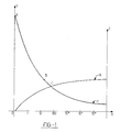
- the abscissa OX represents time, in seconds, on a logarithmic scale
- the ordinate OY represents temperature of the material
- the OZ axis represents the relative contraction of the material.
- the curve T therefore shows the variations in the temperature of the shrinkable polymer as a function of time.
- the temperature at point A, time of injection is 270 ° C, but, as the melt enters the cold mold, the temperature of the material drops rapidly to around 120 ° C, at point B, about 30 seconds later and around 100 ° C, at point C, 45 to 60 seconds after the start of the injection.
- the duration of the operation between closing the mold - containing the ends of the flexible pipes with the connection device - and removing the assembly from the assembly is less than 1 minute .
- This duration will advantageously be compared to the rubber overmolding process, in which the duration of the injection and vulcanization operations is 3 to 6 minutes.
- FIG. 2 represents, by way of nonlimiting examples, some alternative embodiments of the internal tubing (1) which can be made of any rigid material - metallic, composite or plastic - capable of supporting, without deformation , the pressure and the temperature involved in the process.
- View 2a shows an internal tube (1), straight, for the connection, in line, of two flexible pipes (here of the same diameters), made of rubber-based mixtures of identical or different formulations.
- Said internal pipe (1) comprises a collar (2) serving as a stop at the ends of the flexible pipes which will be mounted therein and thus making it possible to ensure that they are properly engaged over the desired length.
- View 2b shows an internal tube (1), straight, comprising a purge device (3) which allows the online connection of two flexible pipes (here of the same diameters) made of rubber mixtures of identical or different formulations.
- Said internal tube (1), straight, with drain device (3) is provided, in its central part with a flange (2) for abutting the ends of the flexible pipes of the same type as that of view 2a.
- View 2c concretizes the realization of a simple diversion which uses a tubing (1), in tee, allowing the connection of a flexible pipe (here provided with a diameter smaller than that of the main pipe), on a main pipe .
- Said internal pipe (1), in a tee is provided with circumferential grooves (4) which promote the mechanical attachment of the main pipes or the bypass on said internal pipe (1).
- the number, the shape, the depth and the arrangement of said grooves (4) are obviously adaptable as a function of the modules of the rubber-based mixtures, reinforced or not, which constitute the flexible pipes connected, to ensure the best mechanical connection.
- the rigid internal tubes (1) can take more complex shapes (not shown) - such as Y to make a simple branch not perpendicular to the main flexible pipe or X to make multiple branches - and may or may not be provided with grooves ( 4) and the collar (2).
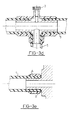
- View 3 illustrates different applications of the connection device which is the subject of the invention.
- View 3a shows the use of a simple purge device.
- the flexible pipes (here of the same diameter) (5) are mounted at the ends of the straight tube (1) comprising the purge device (3), until they come up against the flange (2).
- the contraction of said retractable polymer ensures the hooping of the wall of the flexible pipes (5) in the zones FF ⁇ , by compressing said wall between the rigid internal tubing (1) and the external wrapping element (6).
- View 3b shows the application of the connection device to the realization of a simple derivation.
- the main flexible and bypass pipes (5) are mounted on the corresponding branches of the rigid internal tube (1), in a tee until abutting on the flanges (2).
- the external wrapping element (6) is then molded under the conditions described above in order to hoop the walls of the ends of the flexible pipes (5) against the rigid internal tubing (1).
- said internal tubing (1) in a tee, includes grooves (4) improving the mechanical connection with the ends of the main flexible and diversion pipes (5).
- View 3c shows the application of the connection device to a multiple bypass.
- the ends of the main flexible and diversion pipes (5) are mounted up to the collar (2) of the different branches of the rigid internal tubing (1), in the shape of an X which includes grooves (4) for mechanical connection.
- the external wrapping element (6) then hoops the walls of the ends of the flexible pipes (5) against the rigid internal pipe (1).
- an adhesive (7) has been added between the rigid internal tubing (1), in X, and the internal coating of the ends of the flexible pipes (5), as well as an adhesive (7) between the external wrapping element (6) and the external coating of the ends of the flexible pipes (5), said adhesive being able to be identical in composition or different, depending on the nature of the rubber-based mixtures which constitute the flexible pipes.
- the 3d view illustrates, in the same way, the application of the connection device to the assembly, in the same area, of a bypass and a purge device (3).
- the view 3e represents a device for connecting a flexible pipe (5) to the end piece (8), generally metallic, of an apparatus or of a motor member, said end piece (8) in front, obviously being removable for be inserted into the mold with the end of the flexible pipe (5), because it acts as an internal tube.
- the process for producing the device for connecting and / or connecting flexible pipes which is the subject of the invention has the following advantages: - it does not affect the intrinsic resistance of the main flexible pipe, since it requires no drilling, - it is easy to implement and does not require any special equipment since it uses conventional processing machines from the polymer industry, - it saves time, energy and immobilization of tools, since its duration is very short compared to that of a rubber overmolding, - thanks to the shrinking, it adapts to the manufacturing tolerances of the flexible pipes themselves, since a difference in wall thickness can be compensated for by injecting the corresponding volume of the shrinkable polymer, - it ensures the safety of staff and the workplace, avoiding the handling of dangerous solvents, - finally, it considerably reduces the need and the number of checks required on flexible connection pipes, saving time and personnel.
- connection and / or connection device offers the following advantages: - it authorizes the production of diversions or the installation of drain systems in areas even far from the end of the flexible pipe, - it allows branching connections even if the diameters are equal to those of the main flexible pipes, - it makes it possible to place the purge system in the very zone of the bypass, - It offers the possibility of connecting flexible, main or bypass pipes, made of materials of different natures, for example to withstand environments of different aggressiveness such as heat and oil or grease, for example. It is obvious to the formulator of rubber-based mixtures that a technical-economic optimum cannot be achieved by the use of a single mixture which must satisfy, in neighboring areas, the thermal, dynamic and chemical constraints.
- connection device object of the invention provides a solution to this problem, - it acts as a set of multiple clamps on the walls of flexible pipes on rigid tubing, but without the possibility of sliding and therefore contributes to the safety of connections to machines or engine components, - it brings, by the quality of the material and the surface finish, an aesthetic element that does not offer the more or less effective consolidation aspect of the previous devices, - Finally, and above all, it has a character of reliability not achieved so far, even without interposition of adhesive between the flexible pipes and, on the one hand the internal tubing and / or, on the other hand, the element of external wrapping. In fact, tests have made it possible to demonstrate that a breakout force of more than 80 daN was necessary, at ambient temperature, to separate a pipe with a diameter of 20 millimeters, not adhered, from the connection device.
Abstract
Description
L'invention est relative aux circuits de fluide de toute installation comportant des canalisations souples qui nécessitent des raccordements, des dérivations ou des dispositifs de purge et, en particulier, aux circuits d'échange thermique montés sur des véhicules automobiles ou routiers.The invention relates to the fluid circuits of any installation comprising flexible pipes which require connections, branches or purge devices and, in particular, to the heat exchange circuits mounted on motor or road vehicles.
Lesdits circuits de fluide sont destinés à la liaison de différents matériels - ou organes de moteur dans le cas des véhicules - et doivent présenter, simultanément, des caractéristiques de longévité, - malgré l'environnement hostile dû à la température, à la pression, à la présence de graisses ou d'huile -, de résistance chimique aux fluides véhiculés et d'étanchéité.Said fluid circuits are intended for the connection of different materials - or engine components in the case of vehicles - and must have, simultaneously, longevity characteristics, - despite the hostile environment due to temperature, pressure, the presence of grease or oil -, chemical resistance to the fluids conveyed and sealing.
La liaison entre les matériels ou organes différents implique que les canalisations souples comportent un certain nombre de raccordements, le plus souvent sur des embouts rigides, généralement métalliques, ainsi que des dérivations dont les diamètres peuvent être égaux à celui de la canalisation principale ou différents.The connection between the different materials or bodies implies that the flexible pipes have a certain number of connections, most often on rigid end pieces, generally metallic, as well as branches whose diameters can be equal to that of the main pipe or different.
Alors que les canalisations souples présentent une grande fiabilité grâce à la nature du (ou des) matériau(x) élastomérique(s) constitutif(s) qui comporte(nt), généralement des éléments de renforcement, continus ou discontinus, constitués de matériaux textiles ou métalliques, les zones de raccordement aux matériels ou organes et celles de raccordement des dérivations ou des dispositifs de purge sur la tubulure principale représentent des points faibles où peuvent se produire des fuites ou même des déconnexions provoquées par l'arrachement, sous l'effet de la pression et de la température ou simplement par le fluage des mélanges à base d'élastomères dans ces conditions hostiles.While flexible pipes have a high reliability thanks to the nature of the elastomeric material (s) constituting which comprise (s), generally reinforcing elements, continuous or discontinuous, made of textile materials or metallic, the areas of connection to equipment or bodies and those of connection of diversions or purge devices on the main pipe represent weak points where leaks or even disconnections caused by tearing may occur, under the effect pressure and temperature or simply by creep of the elastomeric mixtures under these hostile conditions.
Pour pallier ces risques, des solutions diverses ont été proposées. Certaines, purement mécaniques, telles que celles décrites dans les brevets EP 88.571 ou DE 3.430.053, concernent l'insertion, dans la canalisation souple, d'une tubulure rigide, généralement métallique, à embase évasée, fixée par un moyen quelconque.To overcome these risks, various solutions have been proposed. Some, purely mechanical, such as those described in patents EP 88,571 or DE 3,430,053, relate to the insertion, in the flexible pipe, of a rigid tubing, generally metallic, with flared base, fixed by any means.
D'autres solutions s'efforcent de prévenir les risques de fuites ou de déconnexion éventuels par un surmoulage, à base de caoutchouc ou de résine synthétique, comme proposé dans les brevets FR 2 506 892, FR 2 562 886 ou EP 0.110.102.Other solutions endeavor to prevent the risks of leaks or possible disconnection by overmolding, based on rubber or synthetic resin, as proposed in patents FR 2 506 892, FR 2 562 886 or EP 0.110.102.
Les solutions existantes présentent un grand nombre d'inconvénients :
- elles affaiblissent la résistance intrinsèque de la canalisation souple principale, en nécessitant un perçage de la paroi qui réduit la section des matériaux qui seront soumis à des sollicitations mécaniques ou détruit, localement, le renforcement de ladite paroi; de plus, ce perçage induit, sur les arêtes du trou ainsi pratiqué, des amorces de déchirure dans une zone qui, en service, sera très fortement sollicitée;
- elles sont de fabrication difficile car elles nécessitent l'introduction, dans la canalisation souple principale, soit de pièces métalliques d'ancrage dans le cas des solutions mécaniques, soit, pour les solutions de surmoulage, de noyaux internes dans la zone de branchement, afin d'assurer la contrepression indispensable lors de l'opération de surmoulage, puis leur extraction une fois l'opération terminée. Pour faciliter ces manipulations, les noyaux internes sont souvent enduits d'un agent lubrifiant, anti-collant du caoutchouc, qui peut contaminer la zone de surmoulage et nuire, ainsi, à la qualité de la liaison intime nécessaire entre le surmoulage et la surface extérieure de la canalisation souple. Par ailleurs, les opérations d'introduction et d'extraction des noyaux internes risquent de provoquer, sur la face interne des canalisations souples principale et secondaire, des blessures qui, même superficielles, créent des amorces de contraintes accélérant la déchéance desdites canalisations;
- elles sont coûteuses à mettre en oeuvre, tant par la pose des inserts métalliques à l'intérieur de la canalisation souple dans le cas des solutions mécaniques, que par la nécessité de deux opérations successives, - l'injection du matériau de surmoulage sur la canalisation souple, puis sa vulcanisation sous pression, dans le moule, qui présente une durée de plusieurs minutes et mobilise, par conséquent, les outillages, dans le deuxième type de solutions;
- elles interdisent la pose de dérivation(s) de même diamètre que celui de la canalisation souple principale, en raison de la dimension nécessaire au passage de l'insert métallique ou du noyau interne; elles interdisent également, pour des raisons de difficulté d'accès, la pose de dérivations dans des zones éloignées de l'extrémité de la canalisation souple principale;
- dans le cas du surmoulage, elles raccourcissent la durée de vie de la canalisation principale en nécessitant un traitement thermique supplémentaire de la zone de branchement qui conduit à une survulcanisation du mélange à base de caoutchouc, donc à un affaiblissement des caractéristiques mécaniques et à une moindre résistance au vieillissement, dans les zones considérées.
- enfin, elles nécessitent un état de propreté parfait des zones à assembler et exigent donc l'emploi de solvants pour les raviver, ce qui nuit à la salubrité du poste de travail et crée des risques d'incendie ou d'explosion dans l'atelier.The existing solutions have a large number of drawbacks:
- They weaken the intrinsic resistance of the main flexible pipe, by requiring a drilling of the wall which reduces the section of the materials which will be subjected to mechanical stresses or locally destroyed, the reinforcement of said wall; moreover, this drilling induces, on the edges of the hole thus made, tear primers in an area which, in service, will be very strongly stressed;
- they are difficult to manufacture because they require the introduction, into the main flexible pipe, either of metal anchoring parts in the case of mechanical solutions, or, for overmolding solutions, of internal cores in the connection area, in order to ensure the essential back pressure during the overmolding operation, then their extraction once the operation is complete. To facilitate these manipulations, the internal cores are often coated with a lubricating agent, anti-sticking of rubber, which can contaminate the overmolding zone and thus harm the quality of the intimate bond necessary between the overmolding and the external surface. flexible pipe. Furthermore, the operations of introducing and extracting the internal cores risk causing, on the internal face of the main and secondary flexible pipes, injuries which, even on the surface, create primers of stress accelerating the forfeiture of said pipes;
- They are expensive to implement, both by installing the metal inserts inside the flexible pipe in the case of mechanical solutions, and by the need for two successive operations, - injection of the overmolding material onto the flexible pipe, then its vulcanization under pressure, into the mold, which has a duration of several minutes and consequently mobilizes the tools, in the second type of solutions;
- They prohibit the installation of bypass (s) of the same diameter as that of the main flexible pipe, due to the size required for the passage of the metal insert or the inner core; they also prohibit, for reasons of difficulty of access, the laying of diversions in areas remote from the end of the main flexible pipe;
- in the case of overmolding, they shorten the life of the main pipeline by requiring additional heat treatment of the connection area which leads to an over-vulcanization of the rubber-based mixture, therefore to a weakening of the mechanical characteristics and to a less resistance to aging in the areas considered.
- finally, they require a perfect state of cleanliness of the areas to be assembled and therefore require the use of solvents to revive them, which affects the salubrity of the work station and creates the risk of fire or explosion in the workshop.
L'analyse de l'art antérieur montre à l'évidence qu'un dispositif permettant de réaliser des raccordements, des branchements de dérivation ou de purges sur une canalisation souple, qui présente les caractéristiques de fiabilité nécessaire tout en étant économique sur le plan de la fabrication n'est pas connu.Analysis of the prior art clearly shows that a device making it possible to make connections, branch connections or purges on a flexible pipe, which has the necessary reliability characteristics while being economical in terms of the manufacturing is not known.
Il faut, de plus, remarquer que l'évolution des technologies industrielles - celle de l'automobile, en particulier, - accroît, de manière considérable les contraintes de service dans les domaines de la température et de la pression, plus particulièrement.It should also be noted that the evolution of industrial technologies - that of the automobile, in particular - considerably increases the service constraints in the areas of temperature and pressure, in particular.
L'invention a donc pour objectif la réalisation, - par des moyens de production moins coûteux et de meilleure salubrité - d'un dispositif de raccordement entre une canalisation souple et soit un embout rigide, soit une (ou plusieurs) dérivation(s), soit un système de purge, qui offre une garantie de fiabilité et de durabilité sous les sollicitations mécaniques, l'agressivité des fluides véhiculés et l'effet de l'environnement hostile, en évitant tout risque de fuite ou de déconnexion.The object of the invention is therefore to produce - by means of less costly and better sanitation production - a connection device between a flexible pipe and either a rigid end piece or one (or more) branch (s), or a purge system, which offers a guarantee of reliability and durability under mechanical stresses, the aggressiveness of the fluids carried and the effect of the hostile environment, avoiding any risk of leakage or disconnection.
L'invention concerne, à la fois le procédé de réalisation et le dispositif de raccordement obtenu par ledit procédé.The invention relates to both the production method and the connection device obtained by said method.
En ce qui concerne le mode de réalisation, l'invention est caractérisée par l'obtention d'un effet de frettage des extrémités des parois de canalisations souples, dans la zone de raccordement, entre une tubulure rigide interne, soit droite soit en forme de té, de Y ou de croix, et un élément d'enveloppage externe, ledit frettage étant obtenu par le traitement thermique, sous pression, d'un matériau polymérique présentant une contraction au cours du refroidissement au moins égale à 1 % de son diamètre initial.With regard to the embodiment, the invention is characterized by obtaining a hooping effect at the ends of the walls of flexible pipes, in the connection zone, between an internal rigid tube, either straight or in the form of tee, Y or cross, and an outer wrapping element, said hooping being obtained by the heat treatment, under pressure, of a polymeric material having a contraction during cooling at least equal to 1% of its initial diameter .
Pour simplifier l'exposé de l'invention, ledit matériau polymérique sera dénommé, par la suite, polymère rétractable.To simplify the description of the invention, said polymeric material will be called, thereafter, shrinkable polymer.
Le procédé de réalisation du dispositif de raccordement comprend principalement, les étapes suivantes :
- les canalisations souples à raccorder sont montées sur les extrémités d'une tubulure interne présentant une forme appropriée,
- les extrémités des canalisations souples ainsi montées sont positionnées dans un moule, à température ambiante, que l'on clôt,
- le polymère rétractable est alors injecté dans le moule, par une machine d'usage courant dans l'industrie de transformation des polymères qui fonctionne à haute température et sous pression élevée,
- en pénétrant dans le moule, le polymère rétractable vient prendre la forme de l'empreinte du moule,
- en se refroidissant, le moulage ainsi obtenu diminue en diamètre, grâce aux propriétés thermiques du polymère rétractable, et vient fretter les parois des extrémités des canalisations souples sur la tubulure interne rigide.The method for producing the connection device mainly comprises the following steps:
- the flexible pipes to be connected are mounted on the ends of an internal tube having an appropriate shape,
the ends of the flexible pipes thus mounted are positioned in a mold, at ambient temperature, which is closed,
the shrinkable polymer is then injected into the mold, by a machine commonly used in the polymer processing industry which operates at high temperature and under high pressure,
- when entering the mold, the shrinkable polymer takes the form of the mold imprint,
- As it cools, the molding thus obtained decreases in diameter, thanks to the thermal properties of the shrinkable polymer, and comes to hoop the walls of the ends of the flexible pipes on the rigid internal tubing.
Les trois dernières phases de l'opération durent, environ, 20 à 60 secondes.
- l'ensemble constitué des canalisations souples et du dispositif de raccordement est démoulé, la contraction se poursuivant lentement avec l'abaissement de la température pour se stabiliser définitivement au bout de 24 heures, à peu près.The last three phases of the operation last, approximately, 20 to 60 seconds.
- the assembly consisting of flexible pipes and the connection device is removed from the mold, the contraction continuing slowly with the lowering of the temperature to stabilize definitively after 24 hours, approximately.
En ce qui concerne le produit ainsi fabriqué, l'invention est caractérisée par le fait que ledit dispositif est composé d'une tubulure interne, rigide, résistant à la pression et à la température mises en jeu dans le procédé et d'un élément d'enveloppage externe, constitué d'une matière polymérique rétractable qui assure un frettage de la paroi des canalisations souples sur ladite tubulure interne.With regard to the product thus manufactured, the invention is characterized in that the said device is composed of an internal, rigid tubing, resistant to the pressure and the temperature involved in the process and of an element d 'outer casing, consisting of a retractable polymeric material which ensures hooping of the wall of the flexible pipes on said internal tube.
Les caractéristiques et variantes de l'invention seront mieux comprises à la lecture de la description accompagnant les dessins, dans lesquels:
- - la figure 1 schématise, sur un graphique, l'évolution de la température et de la contraction du polymère rétractable;
- - la figure 2 représente des variantes de réalisation de la tubulure interne du dispositif de raccordement;
- - la figure 3 illustre différentes applications du dispositif de raccordement.
- - Figure 1 shows schematically, on a graph, the evolution of the temperature and the contraction of the shrinkable polymer;
- - Figure 2 shows alternative embodiments of the internal tubing of the connection device;
- - Figure 3 illustrates different applications of the connection device.
Sur la figure 1, dont le but est d'expliciter le procédé de réalisation, l'abcisse OX représente le temps, en secondes, sur une échelle logarithmique, l'ordonnée OY représente la température de la matière et l'axe OZ représente la contraction relative du matériau.In FIG. 1, the aim of which is to explain the production process, the abscissa OX represents time, in seconds, on a logarithmic scale, the ordinate OY represents temperature of the material and the OZ axis represents the relative contraction of the material.
La courbe T figure donc les variations de la température du polymère rétractable en fonction du temps.The curve T therefore shows the variations in the temperature of the shrinkable polymer as a function of time.
A titre d'exemple non limitatif, l'application du procédé sera décrit pour l'injection d'un polyamide technique ce qui permet de préciser quelques ordres de grandeur, mais il est évident pour le polymériste que d'autres matériaux présentant une possibilité de rétraction thermique supérieure à 1 % pourraient être utilisés.By way of nonlimiting example, the application of the process will be described for the injection of a technical polyamide which makes it possible to specify a few orders of magnitude, but it is obvious to the polymerist that other materials presenting a possibility of thermal shrinkage greater than 1% could be used.
Dans le cas du polyamide technique, la température au point A, moment de l'injection est de 270°C, mais, comme la masse fondue pénètre dans le moule froid, la température de la matière s'abaisse rapidement jusqu'à environ 120°C, au point B, soit environ 30 secondes plus tard et vers 100°C, au point C, 45 à 60 secondes après le début de l'injection.In the case of technical polyamide, the temperature at point A, time of injection is 270 ° C, but, as the melt enters the cold mold, the temperature of the material drops rapidly to around 120 ° C, at point B, about 30 seconds later and around 100 ° C, at point C, 45 to 60 seconds after the start of the injection.
Dans le même temps, comme le montre le courbe R, la contraction du polymère rétractable qui se solidifie passe de 0 à 1 ou 2 % entre le point O et le point C où ladite courbe R tend vers une assymptote, l'évolution entre cette valeur C et la contraction stabilisée, au bout de 24 heures, étant très faible.At the same time, as the curve R shows, the contraction of the shrinking polymer which solidifies goes from 0 to 1 or 2% between point O and point C where said curve R tends towards an asymptote, the evolution between this C value and the stabilized contraction, after 24 hours, being very low.
Sur le plan de la simplicité et de l'économie du procédé, la durée de l'opération entre la fermeture du moule - contenant les extrémités des canalisations souples avec le dispositif de raccordement - et le démoulage de l'ensemble est inférieure à 1 minute. Cette durée sera avantageusement comparée au procédé de surmoulage de caoutchouc, dans lequel la durée des opérations d'injection et de vulcanisation est de 3 à 6 minutes.In terms of simplicity and economy of the process, the duration of the operation between closing the mold - containing the ends of the flexible pipes with the connection device - and removing the assembly from the assembly is less than 1 minute . This duration will advantageously be compared to the rubber overmolding process, in which the duration of the injection and vulcanization operations is 3 to 6 minutes.
L'économie d'énergie et le gain sur l'immobilisation (donc le nombre) des outillages est considérable.The energy saving and the gain on fixed assets (therefore the number) of tools is considerable.
De plus, les opérations de perçage de la canalisation souple principale, d'introduction et d'extraction des noyaux internes primaire (dans la canalisation souple principale) et secondaire (dans l'élément raccordé) sont éliminées comme le sont, d'ailleurs, les opérations de nettoyage et de ravivage par des solvants.In addition, the drilling operations of the main flexible pipe, of introduction and extraction of the primary internal cores (in the main flexible pipe) and secondary (in the connected element) are eliminated as are, moreover, the operations of cleaning and reviving with solvents.
La figure 2 représente, à titre d'exemples non limitatifs, quelques variantes de réalisation de la tubulure interne (1) qui peut être constituée de n'importe quel matériau rigide - métallique, composite ou en matière plastique - capable de supporter, sans déformation, la pression et la température mises en jeu dans le procédé.FIG. 2 represents, by way of nonlimiting examples, some alternative embodiments of the internal tubing (1) which can be made of any rigid material - metallic, composite or plastic - capable of supporting, without deformation , the pressure and the temperature involved in the process.
La vue 2a montre une tubulure interne (1), droite, pour le raccordement, en ligne, de deux canalisations souples (ici de mêmes diamètres), constituées de mélanges à base de caoutchouc de formulations identiques ou différentes. Ladite tubulure interne (1) comporte une collerette (2) servant de butée aux extrémités des canalisations souples qui y seront montées et permettant ainsi de s'assurer qu'elles sont bien engagées sur la longueur désirée.View 2a shows an internal tube (1), straight, for the connection, in line, of two flexible pipes (here of the same diameters), made of rubber-based mixtures of identical or different formulations. Said internal pipe (1) comprises a collar (2) serving as a stop at the ends of the flexible pipes which will be mounted therein and thus making it possible to ensure that they are properly engaged over the desired length.
La vue 2b représente une tubulure interne (1), droite, comportant un dispositif de purge (3) qui permet le raccordement en ligne de deux canalisations souples (ici de mêmes diamètres) constituées de mélanges à base de caoutchouc de formulations identiques ou différentes. Ladite tubulure interne (1), droite, avec dispositif de purge (3) est munie, dans sa partie centrale d'une collerette (2) de butée des extrémités des canalisations souples du même type que celle de la vue 2a.View 2b shows an internal tube (1), straight, comprising a purge device (3) which allows the online connection of two flexible pipes (here of the same diameters) made of rubber mixtures of identical or different formulations. Said internal tube (1), straight, with drain device (3) is provided, in its central part with a flange (2) for abutting the ends of the flexible pipes of the same type as that of view 2a.
La vue 2c concrétise la réalisation d'une dérivation simple qui utilise unt tubulure (1), en té, permettant le raccordement d'une canalisation souple (ici prévue d'un diamètre inférieur à celui de la canalisation principale), sur une canalisation principale. Ladite tubulure interne (1), en té, est munie de cannelures circonférentielles (4) qui favorisent l'accrochage mécanique des canalisations principales ou de la dérivation sur ladite tubulure interne (1). Le nombre, la forme, la profondeur et la disposition desdites cannelures (4) sont bien évidemment adaptables en fonction des modules des mélanges à base de caoutchouc, renforcés ou non, qui constituent les canalisations souples raccordées, pour assurer la meilleure liaison mécanique.View 2c concretizes the realization of a simple diversion which uses a tubing (1), in tee, allowing the connection of a flexible pipe (here provided with a diameter smaller than that of the main pipe), on a main pipe . Said internal pipe (1), in a tee, is provided with circumferential grooves (4) which promote the mechanical attachment of the main pipes or the bypass on said internal pipe (1). The number, the shape, the depth and the arrangement of said grooves (4) are obviously adaptable as a function of the modules of the rubber-based mixtures, reinforced or not, which constitute the flexible pipes connected, to ensure the best mechanical connection.
Les tubulures internes rigides (1) peuvent prendre des formes plus complexes (non représentées) - telles que Y pour réaliser une dérivation simple non perpendiculaire à la canalisation souple principale ou X pour réaliser des dérivations multiples - et peuvent être munies ou non des cannelures (4) et de la collerette (2).The rigid internal tubes (1) can take more complex shapes (not shown) - such as Y to make a simple branch not perpendicular to the main flexible pipe or X to make multiple branches - and may or may not be provided with grooves ( 4) and the collar (2).
Pour améliorer encore la fiabilité du raccordement, il est possible d'utiliser une liaison adhésive entre la tubulure interne (1) et les extrémités des canalisations souples principales ou de dérivation qui y sont montées.To further improve the reliability of the connection, it is possible to use an adhesive connection between the internal tubing (1) and the ends of the main flexible or branch pipes which are mounted therein.
La vue 3 illustre différentes applications du dispositif de raccordement objet de l'invention.View 3 illustrates different applications of the connection device which is the subject of the invention.
La vue 3a montre l'utilisation à un simple dispositif de purge. Les canalisations souples (ici de même diamètre) (5) sont montées aux extrémités de la tubulure droite (1) comportant le dispositif de purge (3), jusqu'à venir buter sur la collerette (2).View 3a shows the use of a simple purge device. The flexible pipes (here of the same diameter) (5) are mounted at the ends of the straight tube (1) comprising the purge device (3), until they come up against the flange (2).
Après mise en place, par le procédé d'injection du polymère rétractable précédemment décrit, de l'élément d'enveloppage externe (6), la contraction dudit polymère rétractable vient assurer le frettage de la paroi des canalisations souples (5) dans les zones FFʹ, en comprimant ladite paroi entre la tubulure interne rigide (1) et l'élément d'enveloppage externe (6).After positioning, by the method of injection of the retractable polymer described above, of the external wrapping element (6), the contraction of said retractable polymer ensures the hooping of the wall of the flexible pipes (5) in the zones FFʹ, by compressing said wall between the rigid internal tubing (1) and the external wrapping element (6).
La vue 3b montre l'application du dispositif de raccordement à la réalisation d'une dérivation simple. Les canalisations souples principales et de dérivation (5) sont montées sur les branches correspondantes de la tubulure interne rigide (1), en té jusqu'à venir buter sur les collerettes (2).View 3b shows the application of the connection device to the realization of a simple derivation. The main flexible and bypass pipes (5) are mounted on the corresponding branches of the rigid internal tube (1), in a tee until abutting on the flanges (2).
L'élément d'enveloppage externe (6) est alors moulé dans les conditions décrites précédemment pour venir fretter les parois des extrémités des canalisations souples (5) contre la tubulure interne rigide (1). Dans la réalisation illustrée, ladite tubulure interne (1), en té, comporte des cannelures (4) améliorant la liaison mécanique avec les extrémités des canalisations souples (5) principales et de dérivation.The external wrapping element (6) is then molded under the conditions described above in order to hoop the walls of the ends of the flexible pipes (5) against the rigid internal tubing (1). In the illustrated embodiment, said internal tubing (1), in a tee, includes grooves (4) improving the mechanical connection with the ends of the main flexible and diversion pipes (5).
La vue 3c montre l'application du dispositif de raccordement à une dérivation multiple. Les extrémités des canalisations souples principales et de dérivation (5) sont montées jusqu'à la collerette (2) des différentes branches de la tubulure interne rigide (1), en forme de X qui comporte des cannelures (4) de liaison mécanique. Comme dans les vues précédentes, l'élément d'enveloppage externe (6) vient alors fretter les parois des extrémités des canalisations souples (5) contre la tubulure interne rigide (1).View 3c shows the application of the connection device to a multiple bypass. The ends of the main flexible and diversion pipes (5) are mounted up to the collar (2) of the different branches of the rigid internal tubing (1), in the shape of an X which includes grooves (4) for mechanical connection. As in the previous views, the external wrapping element (6) then hoops the walls of the ends of the flexible pipes (5) against the rigid internal pipe (1).
Dans la variante illustrée, il a été ajouté un adhésif (7) entre la tubulure interne rigide (1), en X, et le revêtement interne des extrémités des canalisations souples (5), ainsi qu'un adhésif (7) entre l'élément d'enveloppage externe (6) et le revêtement extérieur des extrémités des canalisations souples (5), ledit adhésif pouvant être identique en composition ou différent, selon la nature des mélanges à base de caoutchouc qui constituent les canalisations souples.In the illustrated variant, an adhesive (7) has been added between the rigid internal tubing (1), in X, and the internal coating of the ends of the flexible pipes (5), as well as an adhesive (7) between the external wrapping element (6) and the external coating of the ends of the flexible pipes (5), said adhesive being able to be identical in composition or different, depending on the nature of the rubber-based mixtures which constitute the flexible pipes.
La vue 3d illustre, de la même manière, l'application du dispositif de raccordement au montage, dans la même zone, d'une dérivation et d'un dispositif de purge (3).The 3d view illustrates, in the same way, the application of the connection device to the assembly, in the same area, of a bypass and a purge device (3).
La vue 3e représente un dispositif de raccordement d'une canalisation souple (5) sur l'embout (8), généralement métallique, d'un appareil ou d'un organe de moteur, ledit embout (8) devant, évidemment être démontable pour être inséré dans le moule avec l'extrémité de la canalisation souple (5), car il tient le rôle de tubulure interne.The view 3e represents a device for connecting a flexible pipe (5) to the end piece (8), generally metallic, of an apparatus or of a motor member, said end piece (8) in front, obviously being removable for be inserted into the mold with the end of the flexible pipe (5), because it acts as an internal tube.
Il est évident, pour l'homme de l'art, que les différentes variantes précédemment décrites telles que la présence des cannelures (4), de la collerette (2), l'utilisation d'adhésif (7) entre le revêtement interne des extrémités des canalisations souples (5) et la tubulure interne (1) et/ou entre le revêtement externe des extrémités desdites canalisations souples (5) et l'élément extérieur d'enveloppage (6) peuvent être utilisées de manière isolée ou en combinaison sur les différentes formes de raccordement et de branchement simples ou multiples.It is obvious, for those skilled in the art, that the various variants described above such as the presence of the grooves (4), the flange (2), the use of adhesive (7) between the internal coating of the ends of the flexible pipes (5) and the internal tubing (1) and / or between the external coating of the ends of said flexible pipes (5) and the outer casing element (6) can be used individually or in combination on the different forms of connection and connection, single or multiple.
En conclusion, le procédé de réalisation du dispositif de raccordement et/ou de branchement de canalisations souples objet de l'invention présente les avantages suivants :
- il n'affecte pas la résistance intrinsèque de la canalisation souple principale, puisqu'il n'exige aucun perçage,
- il est facile à mettre en oeuvre et ne requiert pas de matériel particulier puisqu'il utilise des machines de transformation classiques de l'industrie des polymères,
- il est économe en temps, en énergie et en immobilisation d'outillage, puisque sa durée est très courte par rapport à celle d'un surmoulage de caoutchouc,
- grâce au frettage, il s'adapte aux tolérances de fabrication des canalisations souples elles-mêmes, puisqu'une différence d'épaisseur de la paroi peut être compensée par l'injection du volume correspondant du polymère rétractable,
- il assure la sécurité du personnel et du poste de travail, en évitant la manipulation de solvants dangereux,
- enfin, il réduit considérablement la nécessité et le nombre des contrôles nécessaires sur les canalisations souples à branchement, apportant une économie de temps et de personnel. En effet, pour que puisse se produire le frettage de la paroi des canalisations souples, il est nécessaire que le remplissage du moule s'opère sans manque de matière. Cette qualité du remplissage peut être vérifiée par un simple contrôle visuel, un mauvais remplissage se traduisant, immanquablement, par des défauts de surface ou de forme. Cet élément de réduction des coûts de contrôle devient important lorsque l'on sait que, pour les conduits de fluides des véhicules, par exemple, les cahiers des charges imposent des essais de plusieurs milliers de cycles en pression et sans pression sur les canalisations souples à dérivations.In conclusion, the process for producing the device for connecting and / or connecting flexible pipes which is the subject of the invention has the following advantages:
- it does not affect the intrinsic resistance of the main flexible pipe, since it requires no drilling,
- it is easy to implement and does not require any special equipment since it uses conventional processing machines from the polymer industry,
- it saves time, energy and immobilization of tools, since its duration is very short compared to that of a rubber overmolding,
- thanks to the shrinking, it adapts to the manufacturing tolerances of the flexible pipes themselves, since a difference in wall thickness can be compensated for by injecting the corresponding volume of the shrinkable polymer,
- it ensures the safety of staff and the workplace, avoiding the handling of dangerous solvents,
- finally, it considerably reduces the need and the number of checks required on flexible connection pipes, saving time and personnel. Indeed, so that the hooping of the wall of the flexible pipes can occur, it is necessary that the filling of the mold takes place without lack of material. This filling quality can be checked by a simple visual check, a bad filling inevitably resulting in surface or shape defects. This element of reducing control costs becomes important when it is known that, for the fluid conduits of vehicles, for example, the specifications impose tests of several thousand cycles of pressure and without pressure on the flexible pipes to leads.
Quant au dispositif de branchement et/ou de raccordement, il offre les avantages suivants :
- il autorise la réalisation de dérivations ou la pose de systèmes de purge dans des zones même éloignées de l'extrémité de la canalisation souple,
- il permet le branchement de dérivations même si les diamètres sont égaux à ceux des canalisations souples principales,
- il permet de placer le système de purge dans la zone même de la dérivation,
- il offre la possibilité de raccorder des canalisations souples, principales ou de dérivation, réalisées dans des matériaux de natures différentes, par exemple pour résister à des environnements d'agressivités différentes tels que chaleur et huile ou graisses, par exemple. Il est évident pour le formulateur de mélanges à base de caoutchouc qu'un optimum technico-économique ne peut être atteint par l'emploi d'un mélange unique devant satisfaire, dans des zones voisines, aux contraintes thermiques, dynamiques et chimiques. Mais le polymériste sait aussi que tous les matériaux ne sont pas compatibles entre eux et qu'il est parfois impossible d'assurer une liaison adhésive fiable entre deux mélanges. L'utilisation du dispositif de raccordement objet de l'invention apporte alors une solution à ce problème,
- il agit comme un ensemble de colliers de serrage multiple des parois de canalisations souples sur une tubulure rigide, mais sans possibilité de glissement et contribue, de ce fait, à la sécurité des branchements sur les machines ou les organes du moteur,
- il apporte, par la qualité du matériau et du fini de surface un élément d'esthétique que n'offre pas l'aspect de consolidation, plus ou moins efficace, des dispositifs antérieurs,
- enfin, et surtout, il présente un caractère de fiabilité non atteint jusque là, même sans interposition d'adhésif entre les canalisations souples et, d'une part la tubulure interne et/ou, d'autre part, l'élément d'enveloppage externe. En effet, des essais ont permis de mettre en évidence qu'une force d'arrachement de plus de 80 daN était nécessaire, à température ambiante, pour séparer une canalisation d'un diamètre de 20 millimètres, non adhérisée, du dispositif de raccordement.As for the connection and / or connection device, it offers the following advantages:
- it authorizes the production of diversions or the installation of drain systems in areas even far from the end of the flexible pipe,
- it allows branching connections even if the diameters are equal to those of the main flexible pipes,
- it makes it possible to place the purge system in the very zone of the bypass,
- It offers the possibility of connecting flexible, main or bypass pipes, made of materials of different natures, for example to withstand environments of different aggressiveness such as heat and oil or grease, for example. It is obvious to the formulator of rubber-based mixtures that a technical-economic optimum cannot be achieved by the use of a single mixture which must satisfy, in neighboring areas, the thermal, dynamic and chemical constraints. But the polymerist also knows that not all materials are compatible with each other and that it is sometimes impossible to ensure a reliable adhesive bond between two mixtures. The use of the connection device object of the invention then provides a solution to this problem,
- it acts as a set of multiple clamps on the walls of flexible pipes on rigid tubing, but without the possibility of sliding and therefore contributes to the safety of connections to machines or engine components,
- it brings, by the quality of the material and the surface finish, an aesthetic element that does not offer the more or less effective consolidation aspect of the previous devices,
- Finally, and above all, it has a character of reliability not achieved so far, even without interposition of adhesive between the flexible pipes and, on the one hand the internal tubing and / or, on the other hand, the element of external wrapping. In fact, tests have made it possible to demonstrate that a breakout force of more than 80 daN was necessary, at ambient temperature, to separate a pipe with a diameter of 20 millimeters, not adhered, from the connection device.
L'homme de l'art peut, bien entendu, apporter au procédé et au dispositif décrits précédemment ainsi qu'à leurs applications illustrées à titre d'exemples non limitatifs, diverses modifications sans sortir du cadre de l'invention.Those skilled in the art can, of course, make various modifications to the method and the device described above as well as to their applications illustrated by way of non-limiting examples without departing from the scope of the invention.
Claims (8)
Applications Claiming Priority (2)
| Application Number | Priority Date | Filing Date | Title |
|---|---|---|---|
| FR8603972A FR2596133B1 (en) | 1986-03-20 | 1986-03-20 | METHOD FOR MANUFACTURING A CONNECTION AND / OR CONNECTION DEVICE FOR FLEXIBLE PIPES AND CONNECTION AND / OR CONNECTION DEVICE CARRIED OUT ACCORDING TO THIS METHOD |
| FR8603972 | 1986-03-20 |
Publications (2)
| Publication Number | Publication Date |
|---|---|
| EP0243216A1 true EP0243216A1 (en) | 1987-10-28 |
| EP0243216B1 EP0243216B1 (en) | 1990-07-04 |
Family
ID=9333329
Family Applications (1)
| Application Number | Title | Priority Date | Filing Date |
|---|---|---|---|
| EP87400482A Expired - Lifetime EP0243216B1 (en) | 1986-03-20 | 1987-03-05 | A branching device and/or a connection for flexible pipings |
Country Status (19)
| Country | Link |
|---|---|
| US (1) | US5033775A (en) |
| EP (1) | EP0243216B1 (en) |
| JP (2) | JP2630333B2 (en) |
| KR (1) | KR950007635B1 (en) |
| CN (1) | CN1017644B (en) |
| AT (1) | ATE54360T1 (en) |
| AU (1) | AU591762B2 (en) |
| BR (1) | BR8701272A (en) |
| CA (1) | CA1324244C (en) |
| DE (1) | DE3763521D1 (en) |
| ES (1) | ES2017097B3 (en) |
| FR (1) | FR2596133B1 (en) |
| GR (1) | GR3001014T3 (en) |
| HU (1) | HU200628B (en) |
| MA (1) | MA20902A1 (en) |
| MX (1) | MX170452B (en) |
| PT (1) | PT84523B (en) |
| SU (1) | SU1706400A3 (en) |
| ZA (1) | ZA871903B (en) |
Cited By (11)
| Publication number | Priority date | Publication date | Assignee | Title |
|---|---|---|---|---|
| FR2658770A1 (en) * | 1990-02-28 | 1991-08-30 | Caoutchouc Manuf Plastique | WINDOW WASHER LIQUID HEATER ON ENGINE COOLANT LIQUID CIRCUIT. |
| GB2245947A (en) * | 1990-07-12 | 1992-01-15 | Saiag Ind Spa | A branch connector for connection between a main flexible pipe and a secondary flexible pipe with sleeve moulded in situ |
| EP0564990A1 (en) * | 1992-04-07 | 1993-10-13 | SAIAG INDUSTRIA S.p.A. | A connection and/or T-joint for flexible tubes |
| EP0577492A1 (en) * | 1992-07-03 | 1994-01-05 | Hutchinson | Method and apparatus for connecting pipes and branching device |
| US5447341A (en) * | 1988-06-13 | 1995-09-05 | Metzeler Automotive Profiles Gmbh | Molder rubber hose branch |
| WO1996014533A1 (en) * | 1994-11-03 | 1996-05-17 | Pipe Couplings (A/Asia) Pty. Limited | Coupling arrangements for pipes and pipe fittings |
| US5773036A (en) * | 1994-02-23 | 1998-06-30 | Phoenix Aktiengesellschaft | Device and method for extrusion-coating tubes or compound tubular connection fittings with rubber or plastic |
| DE19907736A1 (en) * | 1999-02-23 | 2000-08-24 | Volkswagen Ag | Sealed joint in a vehicle motor fuel line has a shrunk hose section over the joint which is heat-shrunk in place for a durable and leak-free joint seal |
| US6220634B1 (en) | 1999-02-08 | 2001-04-24 | The Goodyear Tire & Rubber Company | Branched hose construction |
| FR2815694A1 (en) | 2000-10-23 | 2002-04-26 | Gates Corp | Positioning device used in assembly of pipe joint, includes over-molded gripping ring, joining section and plate locating annular compression collar |
| FR2871871A1 (en) | 2004-06-17 | 2005-12-23 | Trelleborg Fluid Systems Geie | Flexible pipe e.g. cooling circuit, connecting device for rigid internal pipe, has passage section reducer provided as traversing tubular body, where body includes external radial units such as fixed stud for expansion of connecting zone |
Families Citing this family (36)
| Publication number | Priority date | Publication date | Assignee | Title |
|---|---|---|---|---|
| DE3713064C1 (en) * | 1987-04-16 | 1988-11-17 | Metzeler Gmbh | Process for the production of molded hose branches made of rubber |
| FR2639088B1 (en) * | 1988-11-17 | 1990-12-28 | Caoutchouc Manuf Plastique | COUPLING FOR FLEXIBLE PIPE WITH INTERLOCKING BY TURNING O-RING ON A LOW ANGLE CONE |
| JPH02136896U (en) * | 1989-04-20 | 1990-11-15 | ||
| JPH0645756Y2 (en) * | 1989-10-30 | 1994-11-24 | 豊田合成株式会社 | Hose connection structure |
| IT220447Z2 (en) * | 1990-06-08 | 1993-09-22 | Italiana Serrature Torino | CONNECTION GROUP FOR CIRCUITS OF CIRCULATION OF THE COOLANT LIQUID OF A VEHICLE ENGINE |
| US5335944A (en) * | 1991-03-25 | 1994-08-09 | Toyoda Gosei Co., Ltd. | Hose coupling structure |
| JPH0826955B2 (en) * | 1991-03-25 | 1996-03-21 | 豊田合成株式会社 | Hose fastening structure |
| JP2513090B2 (en) * | 1991-05-09 | 1996-07-03 | 豊田合成株式会社 | Branch hose |
| US5381832A (en) * | 1992-10-06 | 1995-01-17 | Toyoda Gosei Co., Ltd. | Branched hose connector |
| DE4239909C1 (en) * | 1992-11-27 | 1994-05-05 | Rasmussen Gmbh | Tubular plastic connector for flexible lines - comprises fibre reinforced first part with low creep, injected onto unreinforced second part |
| US5411300A (en) * | 1993-03-16 | 1995-05-02 | Toyoda Gosei Co., Ltd. | Hose connecting assembly |
| FR2726626B1 (en) | 1994-11-07 | 1996-12-20 | Hutchinson | DEVICE FOR CONNECTING A PIPE TO AN INSERT |
| US5573283A (en) * | 1995-01-23 | 1996-11-12 | Dayco Products, Inc. | Branched hose construction, part therefor and methods of making the same |
| US5743569A (en) * | 1996-10-15 | 1998-04-28 | Cooper Tire & Rubber Company | Repairable molded-in-place hose connections |
| US5988689A (en) * | 1997-12-26 | 1999-11-23 | Central Plastics Company | Heat-shrinkable electrofusion fittings and methods |
| CA2319473C (en) | 1998-03-13 | 2005-08-30 | The Gates Corporation | Molded hose joint assembly |
| WO2000073039A1 (en) * | 1999-06-01 | 2000-12-07 | Stant Manufacturing Inc. | Weldable mount for fuel systems component |
| NO20001606L (en) * | 2000-03-28 | 2001-10-01 | Nexans | Shot in offshore umbilical hose |
| KR100477145B1 (en) * | 2000-08-22 | 2005-04-29 | 권혁중 | A socket for coupling drainpipes assembly method |
| AUPR113300A0 (en) * | 2000-10-31 | 2000-11-23 | Eli Lilly And Company | Pour-on application method and devices |
| US20020125715A1 (en) * | 2001-03-12 | 2002-09-12 | Alpha-Western Corporation Dba Aquatemp Products Corporation | Fitting and pipe section for jetted bath heaters |
| ITMI20012112A1 (en) * | 2001-10-12 | 2003-04-12 | Aquajet S R L | METHOD OF REALIZATION OF A JOINT OF A JOINT SLEEVE TO ONE OR MORE DISTRIBUTION PIPES OF A FLUID |
| US7503594B2 (en) * | 2003-09-09 | 2009-03-17 | Westinghouse Savannah River Company | Expanding hollow metal rings |
| US20060243453A1 (en) * | 2005-04-27 | 2006-11-02 | Mckee L M | Tubing connector |
| US8424923B2 (en) * | 2005-10-21 | 2013-04-23 | Dow Corning Corporation | Fluid transfer assembly |
| JP5286771B2 (en) * | 2007-01-26 | 2013-09-11 | トヨタ自動車株式会社 | Fuel cell system |
| US7975724B2 (en) * | 2009-06-19 | 2011-07-12 | Ward David P | Hose bend bleeder for ammonia application system |
| US8220126B1 (en) | 2009-11-13 | 2012-07-17 | Mercury Plastics, Inc. | Barbed metal insert overmolding using crosslinked polymers |
| US8844111B1 (en) | 2009-11-13 | 2014-09-30 | Mercury Plastics, Inc. | Barbed metal insert overmolding using crosslinked polymers |
| US9273881B2 (en) * | 2009-11-24 | 2016-03-01 | Climate Recovery Ind. Ab | Connecting piece and a method and tool for its manufacture |
| US8851308B2 (en) * | 2009-12-10 | 2014-10-07 | Alcon Research, Ltd. | Systems and methods for composite frame systems |
| WO2012150991A2 (en) * | 2011-03-03 | 2012-11-08 | Emd Millipore Corporation | Tubing and connector and method making the same |
| FR3028915B1 (en) * | 2014-11-21 | 2017-04-21 | Sartorius Stedim Fmt Sas | FLUID CONNECTION SYSTEM AND METHOD OF MANUFACTURE |
| JP6521194B2 (en) * | 2016-12-28 | 2019-05-29 | 東洋紡株式会社 | Resin molded product, and method for producing resin molded product |
| CN106523829A (en) * | 2016-12-31 | 2017-03-22 | 桂林航天工业学院 | Improved pipe fitting connecting device |
| DE102019216518B3 (en) * | 2019-10-25 | 2021-03-25 | Magna Exteriors Gmbh | Vehicle door and its method for producing a vehicle door |
Citations (4)
| Publication number | Priority date | Publication date | Assignee | Title |
|---|---|---|---|---|
| FR1488316A (en) * | 1966-04-27 | 1967-07-13 | Ct De Rech S De Pont A Mousson | Method and device for manufacturing tubular fittings and resulting fittings |
| EP0110102A1 (en) * | 1982-10-26 | 1984-06-13 | Metzeler Kautschuk Gmbh | Process for the production of a hose junction from rubber, and hose thus obtained |
| US4457542A (en) * | 1981-09-21 | 1984-07-03 | Nibco Inc. | Plastic pipe fitting |
| DE3430053C1 (en) * | 1984-08-16 | 1986-01-02 | Phoenix Ag, 2100 Hamburg | T-hose |
Family Cites Families (36)
| Publication number | Priority date | Publication date | Assignee | Title |
|---|---|---|---|---|
| DE336940C (en) * | 1919-11-12 | 1921-05-19 | Helmholz & Pauli | Glass reflector for incandescent lamps arranged horizontally |
| US3315986A (en) * | 1964-05-05 | 1967-04-25 | Carl F Quick | Means and methods for connecting tubular conduits |
| US3415287A (en) * | 1964-08-21 | 1968-12-10 | Raychem Corp | Protective covering and article |
| US3458619A (en) * | 1965-04-13 | 1969-07-29 | Anger Kunststoff | Process for producing molded bodies |
| US3567259A (en) * | 1967-09-29 | 1971-03-02 | Smiths Industries Ltd | Shrunk fit tube coupling |
| US3898369A (en) * | 1968-02-27 | 1975-08-05 | Robin J T Clabburn | Metal coated heat-recoverable articles |
| US3707032A (en) * | 1969-01-23 | 1972-12-26 | Weatherhead Co | Method of forming an abrasion resistant hose assembly |
| US4170296A (en) * | 1970-01-07 | 1979-10-09 | Raychem Corporation | Self-heating articles and process |
| US3975039A (en) * | 1970-11-03 | 1976-08-17 | Raychem Corporation | Heat-recoverable members |
| BE794882A (en) * | 1972-02-15 | 1973-05-29 | Stewing Albert | CHANNEL SHEATH FOR CABLES AND METHOD FOR ITS REALIZATION |
| JPS51135960A (en) * | 1975-05-21 | 1976-11-25 | Hitachi Ltd | Method of producing hose joint |
| US4070044A (en) * | 1976-01-22 | 1978-01-24 | Phillips Petroleum Company | Polymer pipe connection and method to make it |
| US4386984A (en) * | 1978-02-03 | 1983-06-07 | Raychem Corporation | Heat-shrinkable hollow article |
| US4297155A (en) * | 1978-02-03 | 1981-10-27 | Raychem Corporation | Heat-shrinkable hollow article |
| US4287012A (en) * | 1978-04-10 | 1981-09-01 | Raychem Corporation | Recoverable articles |
| US4163117A (en) * | 1978-04-19 | 1979-07-31 | Raychem Corporation | Heat-recoverable articles and their use |
| US4236736A (en) * | 1978-05-01 | 1980-12-02 | Turnbuckle Products Corporation | Hose coupling |
| US4235832A (en) * | 1978-07-31 | 1980-11-25 | Alden Research Foundation | Molding method |
| US4251304A (en) * | 1979-04-19 | 1981-02-17 | Raychem Corporation | Heat-recoverable articles and their use |
| US4264780A (en) * | 1979-05-22 | 1981-04-28 | Raychem Pontoise S.A. | Heat-recoverable articles |
| US4586971A (en) * | 1979-07-19 | 1986-05-06 | Raychem Corporation | Method of joining heat shrinkable closure members |
| US4596732A (en) * | 1980-06-12 | 1986-06-24 | Raychem Corporation | Pleated heat-recoverable tape |
| FR2506892B1 (en) * | 1981-06-01 | 1988-09-09 | Hutchinson Mapa | BYPASS CONNECTION ON FLEXIBLE PIPE AND ITS INSTALLATION METHOD |
| US4514244A (en) | 1981-09-21 | 1985-04-30 | Nibco Inc. | Plastic pipe elements and methods for making same |
| US4497926A (en) * | 1981-12-28 | 1985-02-05 | Raychem Corporation | Elastomer based adhesive compositions |
| EP0088571B1 (en) * | 1982-03-04 | 1986-05-21 | Avon Industrial Polymers Limited | Method of making branches in hoses |
| GB2138527B (en) * | 1983-04-18 | 1986-10-01 | Dunlop Ltd | Improvements in or relating to branched elastomeric hose |
| FR2549196B1 (en) * | 1983-07-13 | 1985-12-27 | Hutchinson | IMPROVEMENTS IN OR RELATING TO BYPASS CONNECTIONS OBTAINED BY MOLDING A COVERING OF JOINT MATERIAL, IN PARTICULAR A TUBULAR RIGID INSERT, AND MANUFACTURING METHOD |
| DE3336940C2 (en) | 1983-10-11 | 1986-03-27 | Phoenix Ag, 2100 Hamburg | T-shaped hose branch made of rubber |
| US4589939A (en) * | 1984-02-17 | 1986-05-20 | Raychem Corporation | Insulating multiple-conductor cables using coated insert means |
| IT8421539V0 (en) * | 1984-04-13 | 1984-04-13 | Euromatic Srl | CONTINUOUS OVEN FOR THE HEAT TREATMENT OF GLASS CONTAINERS OF VARIABLE SIZE. |
| ES278800Y (en) * | 1984-04-13 | 1985-08-01 | Industrias Vulca, S.A. | MULTIPLE CONNECTION PIECE OF FLUID CIRCUITS |
| US4641860A (en) * | 1984-06-25 | 1987-02-10 | Berkley And Company, Inc. | Coupling for flexible tubing |
| US4656070A (en) * | 1984-09-06 | 1987-04-07 | Raychem Corporation | Coextruded recoverable articles |
| US4648628A (en) * | 1985-09-19 | 1987-03-10 | Dayco Products, Inc. | Branched hose construction, T-connector therefor and methods of making the same |
| DE3534620A1 (en) * | 1985-09-28 | 1987-04-02 | Continental Gummi Werke Ag | METHOD FOR PRODUCING BODY HOSES WITH ONE OR SEVERAL SIDE BRANCH HOSES |
-
1986
- 1986-03-20 FR FR8603972A patent/FR2596133B1/en not_active Expired
-
1987
- 1987-03-05 DE DE8787400482T patent/DE3763521D1/en not_active Expired - Lifetime
- 1987-03-05 ES ES87400482T patent/ES2017097B3/en not_active Expired - Lifetime
- 1987-03-05 EP EP87400482A patent/EP0243216B1/en not_active Expired - Lifetime
- 1987-03-05 AT AT87400482T patent/ATE54360T1/en not_active IP Right Cessation
- 1987-03-11 CA CA000531790A patent/CA1324244C/en not_active Expired - Lifetime
- 1987-03-16 ZA ZA871903A patent/ZA871903B/en unknown
- 1987-03-17 MA MA21142A patent/MA20902A1/en unknown
- 1987-03-18 KR KR1019870002464A patent/KR950007635B1/en not_active IP Right Cessation
- 1987-03-19 CN CN87102671A patent/CN1017644B/en not_active Expired
- 1987-03-19 AU AU70406/87A patent/AU591762B2/en not_active Expired
- 1987-03-19 SU SU874202232A patent/SU1706400A3/en active
- 1987-03-19 MX MX005626A patent/MX170452B/en unknown
- 1987-03-19 PT PT84523A patent/PT84523B/en unknown
- 1987-03-20 JP JP62067688A patent/JP2630333B2/en not_active Expired - Lifetime
- 1987-03-20 HU HU871253A patent/HU200628B/en unknown
- 1987-03-20 BR BR8701272A patent/BR8701272A/en not_active IP Right Cessation
- 1987-03-20 JP JP62067687A patent/JPH07101074B2/en not_active Expired - Fee Related
-
1989
- 1989-04-03 US US07/353,381 patent/US5033775A/en not_active Expired - Lifetime
-
1990
- 1990-07-05 GR GR90400221T patent/GR3001014T3/en unknown
Patent Citations (4)
| Publication number | Priority date | Publication date | Assignee | Title |
|---|---|---|---|---|
| FR1488316A (en) * | 1966-04-27 | 1967-07-13 | Ct De Rech S De Pont A Mousson | Method and device for manufacturing tubular fittings and resulting fittings |
| US4457542A (en) * | 1981-09-21 | 1984-07-03 | Nibco Inc. | Plastic pipe fitting |
| EP0110102A1 (en) * | 1982-10-26 | 1984-06-13 | Metzeler Kautschuk Gmbh | Process for the production of a hose junction from rubber, and hose thus obtained |
| DE3430053C1 (en) * | 1984-08-16 | 1986-01-02 | Phoenix Ag, 2100 Hamburg | T-hose |
Cited By (17)
| Publication number | Priority date | Publication date | Assignee | Title |
|---|---|---|---|---|
| US5447341A (en) * | 1988-06-13 | 1995-09-05 | Metzeler Automotive Profiles Gmbh | Molder rubber hose branch |
| EP0446093A1 (en) * | 1990-02-28 | 1991-09-11 | Caoutchouc Manufacture Et Plastiques | Heater for windscreen washer liquid, using the liquid in the engine cooling system |
| US5183099A (en) * | 1990-02-28 | 1993-02-02 | Caoutchouc Manufacture Et Plastiques S.A. | Motor vehicle windshield washer system |
| FR2658770A1 (en) * | 1990-02-28 | 1991-08-30 | Caoutchouc Manuf Plastique | WINDOW WASHER LIQUID HEATER ON ENGINE COOLANT LIQUID CIRCUIT. |
| GB2245947B (en) * | 1990-07-12 | 1994-03-30 | Saiag Ind Spa | A branch connector for connection between a main flexible pipe and a secondary flexible pipe |
| GB2245947A (en) * | 1990-07-12 | 1992-01-15 | Saiag Ind Spa | A branch connector for connection between a main flexible pipe and a secondary flexible pipe with sleeve moulded in situ |
| US5299839A (en) * | 1992-04-07 | 1994-04-05 | Saiag Industria S.P.A. | Connection and/or T-joint for flexible tubes |
| EP0564990A1 (en) * | 1992-04-07 | 1993-10-13 | SAIAG INDUSTRIA S.p.A. | A connection and/or T-joint for flexible tubes |
| FR2693249A1 (en) * | 1992-07-03 | 1994-01-07 | Hutchinson | Method of connecting tubes or pipes, fittings and similar devices obtained by its implementation. |
| EP0577492A1 (en) * | 1992-07-03 | 1994-01-05 | Hutchinson | Method and apparatus for connecting pipes and branching device |
| US5460762A (en) * | 1992-07-03 | 1995-10-24 | Hutchinson | Method of coupling tubes or pipes by using pressure generated by expanding material |
| US5773036A (en) * | 1994-02-23 | 1998-06-30 | Phoenix Aktiengesellschaft | Device and method for extrusion-coating tubes or compound tubular connection fittings with rubber or plastic |
| WO1996014533A1 (en) * | 1994-11-03 | 1996-05-17 | Pipe Couplings (A/Asia) Pty. Limited | Coupling arrangements for pipes and pipe fittings |
| US6220634B1 (en) | 1999-02-08 | 2001-04-24 | The Goodyear Tire & Rubber Company | Branched hose construction |
| DE19907736A1 (en) * | 1999-02-23 | 2000-08-24 | Volkswagen Ag | Sealed joint in a vehicle motor fuel line has a shrunk hose section over the joint which is heat-shrunk in place for a durable and leak-free joint seal |
| FR2815694A1 (en) | 2000-10-23 | 2002-04-26 | Gates Corp | Positioning device used in assembly of pipe joint, includes over-molded gripping ring, joining section and plate locating annular compression collar |
| FR2871871A1 (en) | 2004-06-17 | 2005-12-23 | Trelleborg Fluid Systems Geie | Flexible pipe e.g. cooling circuit, connecting device for rigid internal pipe, has passage section reducer provided as traversing tubular body, where body includes external radial units such as fixed stud for expansion of connecting zone |
Also Published As
| Publication number | Publication date |
|---|---|
| SU1706400A3 (en) | 1992-01-15 |
| AU591762B2 (en) | 1989-12-14 |
| JPS62233591A (en) | 1987-10-13 |
| MA20902A1 (en) | 1987-10-01 |
| ES2017097B3 (en) | 1991-01-01 |
| MX170452B (en) | 1993-08-24 |
| CN87102671A (en) | 1988-02-24 |
| CA1324244C (en) | 1993-11-16 |
| KR950007635B1 (en) | 1995-07-13 |
| EP0243216B1 (en) | 1990-07-04 |
| FR2596133B1 (en) | 1988-08-12 |
| AU7040687A (en) | 1987-09-24 |
| GR3001014T3 (en) | 1991-12-30 |
| US5033775A (en) | 1991-07-23 |
| ZA871903B (en) | 1987-11-25 |
| PT84523B (en) | 1989-11-10 |
| ATE54360T1 (en) | 1990-07-15 |
| JPH07101074B2 (en) | 1995-11-01 |
| CN1017644B (en) | 1992-07-29 |
| KR870009171A (en) | 1987-10-23 |
| HUT47706A (en) | 1989-03-28 |
| FR2596133A1 (en) | 1987-09-25 |
| HU200628B (en) | 1990-07-28 |
| PT84523A (en) | 1987-04-01 |
| BR8701272A (en) | 1988-01-05 |
| JP2630333B2 (en) | 1997-07-16 |
| JPS62233592A (en) | 1987-10-13 |
| DE3763521D1 (en) | 1990-08-09 |
Similar Documents
| Publication | Publication Date | Title |
|---|---|---|
| EP0243216B1 (en) | A branching device and/or a connection for flexible pipings | |
| EP0577492B1 (en) | Method and apparatus for connecting pipes and branching device | |
| EP2707641B1 (en) | Device and method for thermally insulating a region of connection of connection end fittings of two lagged underwater pipes | |
| RU2121100C1 (en) | Sealing member | |
| EP0446093B1 (en) | Heater for windscreen washer liquid, using the liquid in the engine cooling system | |
| EP1597509B1 (en) | Sleeve with insert for repairing high-pressure fluid pipes | |
| RU2344930C2 (en) | Method for manufacture of heat-insulating pipelines and heat-insulating pipelines for transportation of hot or cold fluids | |
| WO2006042925A1 (en) | Underwater pipe comprising an internal liner | |
| EP0148652A1 (en) | Thermal insulating pipe elements used under thermal, hydrostatic and mechanical stresses, application and manufacture of such insulating elements | |
| EP0614034B1 (en) | Hose having means for the visual early detection of a malfunction and its end flanges | |
| US20120211119A1 (en) | Pipe section joining | |
| CA2564109A1 (en) | Method of repairing a leak in a flange of a gas pipe | |
| WO2008043891A2 (en) | High-pressure pipe element comprising an assembly of hooped tubes and method of manufacture | |
| EP3464977B1 (en) | Method for connecting two unitary elements of a conduit for transporting fluids by means of a sleeve | |
| FR2587933A1 (en) | METHOD FOR PRODUCING HOSES COMPRISING ONE OR MORE LATERAL DERIVATION FLEXIBLES, AND FLEXIBLE SO PERFORMED | |
| FR2489463A1 (en) | ANNULAR JOINT FOR SEALING, METHOD FOR CONSTRUCTING THE SAME, MOLDS AND DEVICE FOR IMPLEMENTING SAID METHOD, APPLICATION OF THE SEAL FOR CONNECTING TWO SHEATHERS | |
| EP0045239B1 (en) | Process for effectuating the protection of junctions of electrical conductors | |
| PL185715B1 (en) | Self-adjusting clamp made of at least bidirectionally oriented polymer for use on hoses and pipes | |
| EP0934485B1 (en) | Method for locking the jointing of a plastic tube on a connecting piece | |
| FR2518927A1 (en) | METHOD FOR MANUFACTURING A RUBBER TUBE OR PLASTIC MATERIAL PROVIDED WITH TEXTILE REINFORCEMENT INSERTIONS AND EQUIPPED WITH A LATERAL BRANCH BYPASS HOSE | |
| FR2888306A1 (en) | Flexible tube and connection piece e.g. end piece, joining device, has heat shrinkable sheath type maintenance piece positioned around joining zone of tube and connection piece and shrunk by heating when tube is vulcanized | |
| US20220178491A1 (en) | Molding system for insulated pipe | |
| WO2023247875A1 (en) | Method for assembling flexible elastomer pipes and pipe assembly thus assembled | |
| WO2008132680A2 (en) | Pipes and couplings | |
| EP0606178A1 (en) | Method of producing a thread on an object, in particular for an object made from composite material and object thus obtained |
Legal Events
| Date | Code | Title | Description |
|---|---|---|---|
| PUAI | Public reference made under article 153(3) epc to a published international application that has entered the european phase |
Free format text: ORIGINAL CODE: 0009012 |
|
| AK | Designated contracting states |
Kind code of ref document: A1 Designated state(s): AT BE CH DE ES FR GB GR IT LI LU NL SE |
|
| 17P | Request for examination filed |
Effective date: 19871116 |
|
| 17Q | First examination report despatched |
Effective date: 19890127 |
|
| GRAA | (expected) grant |
Free format text: ORIGINAL CODE: 0009210 |
|
| AK | Designated contracting states |
Kind code of ref document: B1 Designated state(s): AT BE CH DE ES FR GB GR IT LI LU NL SE |
|
| REF | Corresponds to: |
Ref document number: 54360 Country of ref document: AT Date of ref document: 19900715 Kind code of ref document: T |
|
| ITF | It: translation for a ep patent filed |
Owner name: JACOBACCI & PERANI S.P.A. |
|
| REF | Corresponds to: |
Ref document number: 3763521 Country of ref document: DE Date of ref document: 19900809 |
|
| GBT | Gb: translation of ep patent filed (gb section 77(6)(a)/1977) | ||
| REG | Reference to a national code |
Ref country code: GR Ref legal event code: FG4A Free format text: 3001014 |
|
| PLBE | No opposition filed within time limit |
Free format text: ORIGINAL CODE: 0009261 |
|
| STAA | Information on the status of an ep patent application or granted ep patent |
Free format text: STATUS: NO OPPOSITION FILED WITHIN TIME LIMIT |
|
| 26N | No opposition filed | ||
| ITTA | It: last paid annual fee | ||
| PGFP | Annual fee paid to national office [announced via postgrant information from national office to epo] |
Ref country code: BE Payment date: 19940124 Year of fee payment: 8 |
|
| PGFP | Annual fee paid to national office [announced via postgrant information from national office to epo] |
Ref country code: CH Payment date: 19940309 Year of fee payment: 8 |
|
| EPTA | Lu: last paid annual fee | ||
| EAL | Se: european patent in force in sweden |
Ref document number: 87400482.3 |
|
| PG25 | Lapsed in a contracting state [announced via postgrant information from national office to epo] |
Ref country code: LI Effective date: 19950331 Ref country code: BE Effective date: 19950331 Ref country code: CH Effective date: 19950331 |
|
| BERE | Be: lapsed |
Owner name: CAOUTCHOUC MANUFACTURE ET PLASTIQUES Effective date: 19950331 |
|
| REG | Reference to a national code |
Ref country code: CH Ref legal event code: PL |
|
| REG | Reference to a national code |
Ref country code: FR Ref legal event code: ST |
|
| REG | Reference to a national code |
Ref country code: FR Ref legal event code: RN Ref country code: FR Ref legal event code: FC |
|
| REG | Reference to a national code |
Ref country code: FR Ref legal event code: RU |
|
| REG | Reference to a national code |
Ref country code: FR Ref legal event code: JE |
|
| REG | Reference to a national code |
Ref country code: FR Ref legal event code: PC |
|
| REG | Reference to a national code |
Ref country code: FR Ref legal event code: JE |
|
| REG | Reference to a national code |
Ref country code: FR Ref legal event code: CD Ref country code: FR Ref legal event code: TP |
|
| REG | Reference to a national code |
Ref country code: GB Ref legal event code: 732E |
|
| REG | Reference to a national code |
Ref country code: GB Ref legal event code: IF02 |
|
| PGFP | Annual fee paid to national office [announced via postgrant information from national office to epo] |
Ref country code: DE Payment date: 20040430 Year of fee payment: 18 |
|
| PG25 | Lapsed in a contracting state [announced via postgrant information from national office to epo] |
Ref country code: DE Free format text: THE PATENT HAS BEEN ANNULLED BY A DECISION OF A NATIONAL AUTHORITY Effective date: 20050315 |
|
| PGFP | Annual fee paid to national office [announced via postgrant information from national office to epo] |
Ref country code: NL Payment date: 20060216 Year of fee payment: 20 |
|
| PGFP | Annual fee paid to national office [announced via postgrant information from national office to epo] |
Ref country code: AT Payment date: 20060221 Year of fee payment: 20 |
|
| PGFP | Annual fee paid to national office [announced via postgrant information from national office to epo] |
Ref country code: FR Payment date: 20060317 Year of fee payment: 20 |
|
| PGFP | Annual fee paid to national office [announced via postgrant information from national office to epo] |
Ref country code: ES Payment date: 20060327 Year of fee payment: 20 |
|
| PGFP | Annual fee paid to national office [announced via postgrant information from national office to epo] |
Ref country code: GB Payment date: 20060329 Year of fee payment: 20 Ref country code: SE Payment date: 20060329 Year of fee payment: 20 |
|
| PGFP | Annual fee paid to national office [announced via postgrant information from national office to epo] |
Ref country code: IT Payment date: 20060331 Year of fee payment: 20 Ref country code: GR Payment date: 20060331 Year of fee payment: 20 |
|
| PGFP | Annual fee paid to national office [announced via postgrant information from national office to epo] |
Ref country code: LU Payment date: 20060403 Year of fee payment: 20 |
|
| PG25 | Lapsed in a contracting state [announced via postgrant information from national office to epo] |
Ref country code: GB Free format text: LAPSE BECAUSE OF EXPIRATION OF PROTECTION Effective date: 20070304 |
|
| PG25 | Lapsed in a contracting state [announced via postgrant information from national office to epo] |
Ref country code: NL Free format text: LAPSE BECAUSE OF EXPIRATION OF PROTECTION Effective date: 20070305 |
|
| PG25 | Lapsed in a contracting state [announced via postgrant information from national office to epo] |
Ref country code: ES Free format text: LAPSE BECAUSE OF EXPIRATION OF PROTECTION Effective date: 20070306 |
|
| REG | Reference to a national code |
Ref country code: GB Ref legal event code: PE20 |
|
| NLV7 | Nl: ceased due to reaching the maximum lifetime of a patent |
Effective date: 20070305 |
|
| EUG | Se: european patent has lapsed | ||
| REG | Reference to a national code |
Ref country code: ES Ref legal event code: FD2A Effective date: 20070306 |