EP0242871A2 - Molded plastic valve and sealing means therefor - Google Patents
Molded plastic valve and sealing means therefor Download PDFInfo
- Publication number
- EP0242871A2 EP0242871A2 EP19870105909 EP87105909A EP0242871A2 EP 0242871 A2 EP0242871 A2 EP 0242871A2 EP 19870105909 EP19870105909 EP 19870105909 EP 87105909 A EP87105909 A EP 87105909A EP 0242871 A2 EP0242871 A2 EP 0242871A2
- Authority
- EP
- European Patent Office
- Prior art keywords
- valve
- valve member
- recess
- cavity
- port means
- Prior art date
- Legal status (The legal status is an assumption and is not a legal conclusion. Google has not performed a legal analysis and makes no representation as to the accuracy of the status listed.)
- Withdrawn
Links
Images

Classifications
-
- A—HUMAN NECESSITIES
- A61—MEDICAL OR VETERINARY SCIENCE; HYGIENE
- A61M—DEVICES FOR INTRODUCING MEDIA INTO, OR ONTO, THE BODY; DEVICES FOR TRANSDUCING BODY MEDIA OR FOR TAKING MEDIA FROM THE BODY; DEVICES FOR PRODUCING OR ENDING SLEEP OR STUPOR
- A61M1/00—Suction or pumping devices for medical purposes; Devices for carrying-off, for treatment of, or for carrying-over, body-liquids; Drainage systems
- A61M1/71—Suction drainage systems
- A61M1/74—Suction control
- A61M1/741—Suction control with means for varying suction manually
- A61M1/7413—Suction control with means for varying suction manually by changing the cross-section of the line
-
- A—HUMAN NECESSITIES
- A61—MEDICAL OR VETERINARY SCIENCE; HYGIENE
- A61M—DEVICES FOR INTRODUCING MEDIA INTO, OR ONTO, THE BODY; DEVICES FOR TRANSDUCING BODY MEDIA OR FOR TAKING MEDIA FROM THE BODY; DEVICES FOR PRODUCING OR ENDING SLEEP OR STUPOR
- A61M1/00—Suction or pumping devices for medical purposes; Devices for carrying-off, for treatment of, or for carrying-over, body-liquids; Drainage systems
- A61M1/71—Suction drainage systems
- A61M1/77—Suction-irrigation systems
- A61M1/774—Handpieces specially adapted for providing suction as well as irrigation, either simultaneously or independently
-
- A—HUMAN NECESSITIES
- A61—MEDICAL OR VETERINARY SCIENCE; HYGIENE
- A61M—DEVICES FOR INTRODUCING MEDIA INTO, OR ONTO, THE BODY; DEVICES FOR TRANSDUCING BODY MEDIA OR FOR TAKING MEDIA FROM THE BODY; DEVICES FOR PRODUCING OR ENDING SLEEP OR STUPOR
- A61M1/00—Suction or pumping devices for medical purposes; Devices for carrying-off, for treatment of, or for carrying-over, body-liquids; Drainage systems
- A61M1/71—Suction drainage systems
- A61M1/77—Suction-irrigation systems
- A61M1/772—Suction-irrigation systems operating alternately
-
- A—HUMAN NECESSITIES
- A61—MEDICAL OR VETERINARY SCIENCE; HYGIENE
- A61M—DEVICES FOR INTRODUCING MEDIA INTO, OR ONTO, THE BODY; DEVICES FOR TRANSDUCING BODY MEDIA OR FOR TAKING MEDIA FROM THE BODY; DEVICES FOR PRODUCING OR ENDING SLEEP OR STUPOR
- A61M2202/00—Special media to be introduced, removed or treated
- A61M2202/02—Gases
- A61M2202/0208—Oxygen
-
- A—HUMAN NECESSITIES
- A61—MEDICAL OR VETERINARY SCIENCE; HYGIENE
- A61M—DEVICES FOR INTRODUCING MEDIA INTO, OR ONTO, THE BODY; DEVICES FOR TRANSDUCING BODY MEDIA OR FOR TAKING MEDIA FROM THE BODY; DEVICES FOR PRODUCING OR ENDING SLEEP OR STUPOR
- A61M2210/00—Anatomical parts of the body
- A61M2210/10—Trunk
- A61M2210/1025—Respiratory system
- A61M2210/1039—Lungs
-
- Y—GENERAL TAGGING OF NEW TECHNOLOGICAL DEVELOPMENTS; GENERAL TAGGING OF CROSS-SECTIONAL TECHNOLOGIES SPANNING OVER SEVERAL SECTIONS OF THE IPC; TECHNICAL SUBJECTS COVERED BY FORMER USPC CROSS-REFERENCE ART COLLECTIONS [XRACs] AND DIGESTS
- Y10—TECHNICAL SUBJECTS COVERED BY FORMER USPC
- Y10T—TECHNICAL SUBJECTS COVERED BY FORMER US CLASSIFICATION
- Y10T137/00—Fluid handling
- Y10T137/8593—Systems
- Y10T137/86493—Multi-way valve unit
- Y10T137/86574—Supply and exhaust
- Y10T137/8667—Reciprocating valve
-
- Y—GENERAL TAGGING OF NEW TECHNOLOGICAL DEVELOPMENTS; GENERAL TAGGING OF CROSS-SECTIONAL TECHNOLOGIES SPANNING OVER SEVERAL SECTIONS OF THE IPC; TECHNICAL SUBJECTS COVERED BY FORMER USPC CROSS-REFERENCE ART COLLECTIONS [XRACs] AND DIGESTS
- Y10—TECHNICAL SUBJECTS COVERED BY FORMER USPC
- Y10T—TECHNICAL SUBJECTS COVERED BY FORMER US CLASSIFICATION
- Y10T137/00—Fluid handling
- Y10T137/8593—Systems
- Y10T137/86493—Multi-way valve unit
- Y10T137/86847—Pivoted valve unit
- Y10T137/86855—Gate
-
- Y—GENERAL TAGGING OF NEW TECHNOLOGICAL DEVELOPMENTS; GENERAL TAGGING OF CROSS-SECTIONAL TECHNOLOGIES SPANNING OVER SEVERAL SECTIONS OF THE IPC; TECHNICAL SUBJECTS COVERED BY FORMER USPC CROSS-REFERENCE ART COLLECTIONS [XRACs] AND DIGESTS
- Y10—TECHNICAL SUBJECTS COVERED BY FORMER USPC
- Y10T—TECHNICAL SUBJECTS COVERED BY FORMER US CLASSIFICATION
- Y10T137/00—Fluid handling
- Y10T137/8593—Systems
- Y10T137/86493—Multi-way valve unit
- Y10T137/86879—Reciprocating valve unit
Definitions
- This invention concerns a valve and especially a gate valve of all-molded plastic construction and improvements in the design of one or more sealing means which are incorporated therein to render sealing more efficient while greatly reducing cost.
- Such valves may have particular application in systems for suctioning fluids from the lungs and alternatively, for oxygenating the lungs of patients requiring such treatment and as such may be made sufficiently inexpensive to be disposable.
- Gate valves - often called slide valves - operate on the same basic principle.
- the housing or body of the valve contains one or more inlets and, connected thereto, passages through the housing which conduct fluids to one or more outlets.
- the housing includes a recess or slot which receives the slide member or gate, often a flat rectangular or semi-circular member.
- the slide member contains one or more fluid passages or apertures which can be selectively aligned by reciprocation or rotation of the slide member with one or more through passages in the housing or valve body, thus controlling or limiting flow through the valve.
- valves of this type by molding the housing and slide member of plastic, for example by injection molding.
- This type of manufacture obviously can produce a valve less expensively than, for example, where the parts are of metal and particularly where machining and precision fitting of parts is required.
- one side of the valve is connected to a source of suction and to an oxygen source, the outlet of the valve being connected to a catheter which passes into the lungs of a patient to be treated.
- the valve body has fluid passages therethrough which extend from the inlet openings to a single outlet, the valve body further defining a recess perpendicular thereto which receives a slide member or gate.
- the latter is reciprocable or rotatable and defines at least one opening which can be selectively aligned with the aforesaid fluid passages to prevent or interrupt flow to the outlet.
- one other of the important aspects of the present invention is to provide improved sealing means which obviates the above difficulties and which is expected to have use in many other applications other than the disclosed oxygenation/suctioning system.
- the sealing construction disclosed herein (which is a laminated seal) has been used heretofore as a gasket (engines) and as a seal around aircraft canopies and exit doors and has been used to seal medicinal ampules or vials; as used herein it is a significant improvement over the foregoing applications and valve and other sealing configurations found for example in US-A-4,089,506; 3,907,310; 4,111,440; 4,019,535; 4,465,062 and 4,538,607.
- the gate valve sealing means of the invention particularly finds application in inexpensive molded plastic valves which may have to be disposable for hygienic reasons, i.e. in hospital environments.
- the improved seal construction significantly reduces the cost of molding the body of the valve, maintaining close tolerances to achieve effective sealing, and also reduces the cost of the plastic materials chosen for particular valve constructions, while simultaneously providing greatly increased sealing efficiency.
- a valve having a housing of molded plastic material, the housing having a recess to receive an elongated, flat-sided member for slidable movement therein with respect to said housing, the housing having fluid passage means therethrough, the fluid passage means defining aligned, facing orifices in the recess, the slidable member also defining fluid passage means adapted to be brought into and out of alignment with the fluid passage means in the housing, the slidable member including sealing means comprising a laminated member defining fluid passage means generally congruent with the fluid passage means in said member.
- the laminated member has an outer layer of low friction plastic material, for example polytetrafluorethylene, and bonded thereto, an inner layer of resilient material, for example silicone rubber, the layer of resilient material normally being maintained in compression when said slidable member is in the recess in the housing, the outer low friction plastic layer being thereby thrust into sealing contact with the facing portions of the housing.
- low friction plastic material for example polytetrafluorethylene
- resilient material for example silicone rubber
- the invention further includes venting means which is located in the housing on the side thereof closest to the inlet connections for the housing so that contamination from the area in which the slide member is located is substantially obviated.
- the housing includes a special lavage port to permit the introduction of a sterile saline solution as an adjunct to an oxygenation/suctioning procedure.
- Another aspect of the invention is the manner in which the rotary or reciprocable slide member is held in its recess in the valve housing by resilient tab means which acts as a stop to limit movement of the slide member and which secures the slide member in its recess.
- a valve (10) includes a one-piece housing (11) and a moveable slide member (12) which are each molded of a suitable plastic material, by the use of injection molding techniques.
- Housing (11) has two tubular inlet connections (13 and 14) which are each threaded to a plastic tubing (16 and 17), respectively.
- One of the uses of the valve (10) is in conjunction with oxygenation/suctioning systems which permit the alternate oxygenating of the lungs of a patient and the removal of fluid therefrom by suction.
- tubular member (16) may be for example connected to a source of suction and member (17) connected to a source of oxygen.
- the housing (11) includes passages (13a and 14a), respectively, which are in alignment with passages (13b, 14b). The latter are connected with a chamber (18) which is connected to a single cylindrical outlet (19). Outlet (19) is internally recessed at (19a) to receive the end of a catheter (20) whose distal end (not shown) may be inserted into the lungs of a patient for oxygenation/suctioning treatment.
- housing (11) defines a generally rectangular slot or recess (21) which receives the slide member (12) for reciprocal movement therein.
- the lateral ends of slide member (12) have been formed as cylindrical guide sections or posts (12a and 12b) which are received within mating cylindrical end sections (21a, 21b) of housing recess (21).
- the inner ends of post sections (12a and 12b) define two laterally spaced recesses (12c and 12d) which receive coiled compression springs (22), the opposite ends of these springs resting upon the bottom surface of recess (21).
- Slide member (12) can be depressed by the therapist or doctor administering the oxygenation/suctioning treatment by pressing down with the thumb or a forefinger against the upper curved flange (12e) of the slide member, the inner portion of which serves to limit inward movement of the slide member into recess (21).
- springs (22) will return the slide member (12) to the position shown in the figures, which in the illustrated embodiment is the oxygenation position.
- Slide member (12) defines a generally elliptical or elongated aperture (12f) which in the full outer position shown in Figs. 1 and 3 becomes aligned with the tube (17) connected to the oxygen source, while as best seen in Fig. 3 when slide member (12) is depressed within recess (21), the elliptical aperture (12b) is out of alignment with passageway (14a) (oxygen) and is brought into alignment with passageway (13a) (suction).
- slide member (12) has been formed to have an integral leaf spring tab (23) which normally and resiliently projects from a lateral surface of the slide member.
- Housing (11) has been formed with a corresponding recess (24) which receives tab (23) when the slide member (12) has been inserted into housing recess (21) for a distance sufficient to permit tab (23) to spring outwardly and into recess (24).
- tab (23) acts as a stop, adapted to bear against the upper edge of recess (24) to prevent movement of slide member (12) outwardly of the recess beyond the position shown in Figs. 5 and 6.
- one side of slide member (12) defines a generally rectangular recess (26) and that within such recess a laminated sealing member (27) is mounted and affixed by using, for example, a suitable adhesive.
- Sealing member (27) consists of two layers, adhesively bonded together, the outermost layer (28) facing passages (13b and 14b) comprising a layer of low friction plastic material such as polytetrafluorethylene while the inner layer (29) within recess (26) is resilient and may, for example, be of silicone rubber.
- the laminated sealing member (27) extends peripherally around elliptical aperture (12f) in slide member (12). It will be seen and understood (see Fig.
- resilient layer (29) of sealing member (27) causes the resilient layer (29) of sealing member (27) to be more greatly compressed than in the configuration of Fig. 6.
- resilient layer (29) since resilient layer (29) is constantly in compression, in both configurations it operates to force the low friction sheet layer (28) facing passages (13b and 14b) into sealing engagement with the orifice ends of passages (13b and 14b).
- the resilient thrust of layer (29) also acts to force surface (12h) facing passages (13a and 14a) into sealing engagement with the orifice ends of these passages, thereby effecting a complete seal between both sides of the slide member and the passages in the adjacent housing.
- the valve (10) incorporates a venting system which is best seen in connection with Fig. 2.
- Each of passages (13a) (suction) and (14a) (oxygen) includes, respectively, a vent passage (30, 31) which further include check valves (32, 33) to control venting of passages (13a, 14a) through vent orifices (34, 35).
- Check valves (32 and 33) may for example be of a slitted diaphragm type and will each be set to open whenever a preselected pressure differential exists with respect to opposite sides of the diaphragm. Accordingly, should a blockage occur in a catheter during the suctioning mode, air would be admitted through check valve (32) into passage (13a) as soon as a requisite pressure differential exists between the reduced pressure in passage (13a) and atmospheric pressure.
- the check valve (33) has one other useful function.
- the slitted diaphragm construction will permit the introduction therethrough of a needle for injecting a sterile saline solution for lavage.
- the ability of the valve (10) quickly and easily to alternate between suction and oxygenation modes permits such saline solution to break up mucous or other blockages from the lungs encountered during suctioning by lavage which will be simultaneously administered with oxygen until suction flow is reestablished and the lungs are completely clear.
- passages (30, 31) and check valves (32, 33) are positioned relative to slide member (12) and housing recess (21) so that any bacterial contamination from member (12) or recess (21) cannot issue from vent orifices (34 or 35) when check valves (32, 33) are open.
- suction line ( ⁇ 13a) leading to the suction pump exhaust venting system (not shown) remains free from contamination.
- oxygen is vented to atmosphere through valve (33) and vent orifice (35), the surrounding environment remains uncontaminated.
- Fig. 4 illustrates a variation of the valve configuration disclosed in Figs. 1 bo 3. Parts which are the same have been designated by the same reference numerals. Accordingly, valve housing (11) has been formed to have slide recess (21) therein which receives slide member (12 ⁇ ). In the configuration of Fig. 4, it will be seen that oxygen passage (13a ⁇ ) is located above suction passage (14a ⁇ ) and not side-by-side as in the previous embodiment. Consequently, aperture (12f ⁇ ) in the slide member is vertically oriented, as is laminated sealing member (27 ⁇ ). Otherwise, the operation and function of the valve configuration of Fig. 4 is the same as that described in connection with Figs. 1 to 3 and Figs. 5 and 6.
- Valve (40) includes a plastic valve housing (41) molded in two parts (41a and 41b), the housing having separate inlets (42, 43), which may be connected to suction and oxygen, respectively, and a single outlet (44) to be connected to a catheter (45).
- Passages (42a, 43a) are formed within housing (41) and lead to a generally semi-circular recess (46) which receives a otary slide member (47) therein.
- the latter includes an integral resilient tab (48) the upper curved end (48a) of which is adapted to be received and to snap into a mating recess (49) (Fig. 9) in the valve housing (41) when the parts are assembled.
- the slide member (47) has been formed with outer flanges (47a, 47b) each of which can be alternately depressed by the therapist or doctor to rotate member (47) into the oxygenation or suctioning positions. Flanges (47a and 47b) will abut the housing (41) to define these two operational positions. Rotation of slide member (47) is about the curved end portion (48a) of tab (48) and correspondingly curved portion of recess (49).
- Slide member (47) defines an aperture (47c) therein which will register with one or the other of passages (42a and 43a), respectively, when member (47) assumes its alternate positions. Accordingly and by this means alternate fluid connection can be made of inlets (42 and 43) to outlet (44). Slide member (47) further defines a recess (47d) which receives a laminated sealing member (50) whose periphery includes the curved section (50a) and straight peripheral sides (50b) through (50e). Sealing member (50) is a bonded laminate of two layers, i.e. a resilient backing layer (51), adhesively mounted in recess (47d), and a low friction sheet layer (52), which faces the inner orifice end of outlet (44).
- laminated sealing member (50) is the same as described in respect of the sealing member (27) of Figs. 1 through 6. It will therefore be understood that the combination of constant resilient force applied by resilient backing layer (51) acting upon the low friction surface of sheet layer (52) produces a highly efficient sealing of both sides of slide member (47) with respect to the orifice ends of the passages through the valve (40), and that sealing member (50) is capable of compensating for the fairly large molding tolerances which occur between the respective widths of recess (46) and the rotary slide member (47).
- Valve (40) also includes the non-contaminating vent system described in connection with the first embodiment.
- vent orifices (53, 53) and slitted diaphragm check valves (55, 56) are illustrated in Fig. 8.
- valve (40) is provided with a lavage port (57) and a passage (58) through which a needle may be inserted to inject a sterile saline solution into the oxygen passage (42a).
- the lavage procedure has been described in connection with the embodiment of Figs. 1 through 6.
- lavage passage (58) is very narrow but sufficiently wide to admit a needle and consequently when oxygen is flowing in passage (42a) and passage (58) is not in use, ambiant air will be asperated into this passage by the venturi effect produced by the flow of oxygen past the inner end of passage (58).
- valve configurations disclosed herein are ideally of all molded plastic construction and lend themselves to high production and inexpensive cost.
- laminated sealing member disclosed herein provides extremely efficient low-friction sealing and makes possible the use of these inexpensive molded plastic techniques.
Abstract
Description
- This invention concerns a valve and especially a gate valve of all-molded plastic construction and improvements in the design of one or more sealing means which are incorporated therein to render sealing more efficient while greatly reducing cost. Such valves may have particular application in systems for suctioning fluids from the lungs and alternatively, for oxygenating the lungs of patients requiring such treatment and as such may be made sufficiently inexpensive to be disposable.
- Gate valves - often called slide valves - operate on the same basic principle. The housing or body of the valve contains one or more inlets and, connected thereto, passages through the housing which conduct fluids to one or more outlets. The housing includes a recess or slot which receives the slide member or gate, often a flat rectangular or semi-circular member. The slide member contains one or more fluid passages or apertures which can be selectively aligned by reciprocation or rotation of the slide member with one or more through passages in the housing or valve body, thus controlling or limiting flow through the valve.
- Attempts have been made to produce valves of this type by molding the housing and slide member of plastic, for example by injection molding. This type of manufacture obviously can produce a valve less expensively than, for example, where the parts are of metal and particularly where machining and precision fitting of parts is required. However, it is difficult, if not impossible, to maintain close tolerances, using present injection molding techniques, between the dimensions of the slide member and the recess in the valve housing which receives the slide member.
- In order to produce an efficient valve, where sealing is effected directly (without the interposition of specific sealing means) between slide member and valve housing, the difference in width between the slide member and its recess would have to be held to say, one hundreth of a millimeter (0,01 mm). It is not unusual when molding valves of this type, however, to be unable to hold tolerances of less than plus or minus one tenth of a millimeter. The use of conventional seals in such circumstances will not satisfactorily solve these wide dimensional differences, and it has been found that to attempt efficient sealing would be to introduce large frictional forces which inhibit movements of the slide member.
- It is one of the important aspects of the present invention to solve these inherent problems in the manufacture of molded plastic valves of this type.
- In the environment in which the present invention is depicted herein, one side of the valve is connected to a source of suction and to an oxygen source, the outlet of the valve being connected to a catheter which passes into the lungs of a patient to be treated. The valve body has fluid passages therethrough which extend from the inlet openings to a single outlet, the valve body further defining a recess perpendicular thereto which receives a slide member or gate. The latter is reciprocable or rotatable and defines at least one opening which can be selectively aligned with the aforesaid fluid passages to prevent or interrupt flow to the outlet. Within the oxygenation/suctioning environment, illustrations of systems and valves of this type, may be found in US-A-4,193,406 and US-A-4,300,550.
- A serious problem shared by these prior valve constructions is their lack of adequate sealing between slide member and fluid passage orifices which greatly impairs the efficiency of the systems incorporating them. Where, for example, fluid is suctioned from, and oxygen is alternatively provided to the lungs, it is imperative and apparent that each operation be performed as expeditiously as possible to minimize potential harm to the patient and leakage of oxygen or bacterially contaminated air to the surrounding environment.
- Therefore, generally speaking, one other of the important aspects of the present invention is to provide improved sealing means which obviates the above difficulties and which is expected to have use in many other applications other than the disclosed oxygenation/suctioning system. The sealing construction disclosed herein (which is a laminated seal) has been used heretofore as a gasket (engines) and as a seal around aircraft canopies and exit doors and has been used to seal medicinal ampules or vials; as used herein it is a significant improvement over the foregoing applications and valve and other sealing configurations found for example in US-A-4,089,506; 3,907,310; 4,111,440; 4,019,535; 4,465,062 and 4,538,607.
- As will be described, the gate valve sealing means of the invention particularly finds application in inexpensive molded plastic valves which may have to be disposable for hygienic reasons, i.e. in hospital environments. The improved seal construction significantly reduces the cost of molding the body of the valve, maintaining close tolerances to achieve effective sealing, and also reduces the cost of the plastic materials chosen for particular valve constructions, while simultaneously providing greatly increased sealing efficiency.
- Other improved features of the new valve construction including an improved non-contaminating valve venting system will become apparent upon examination of the detailed description and drawing.
- In accordance with the present invention, there is disclosed a valve having a housing of molded plastic material, the housing having a recess to receive an elongated, flat-sided member for slidable movement therein with respect to said housing, the housing having fluid passage means therethrough, the fluid passage means defining aligned, facing orifices in the recess, the slidable member also defining fluid passage means adapted to be brought into and out of alignment with the fluid passage means in the housing, the slidable member including sealing means comprising a laminated member defining fluid passage means generally congruent with the fluid passage means in said member. The laminated member has an outer layer of low friction plastic material, for example polytetrafluorethylene, and bonded thereto, an inner layer of resilient material, for example silicone rubber, the layer of resilient material normally being maintained in compression when said slidable member is in the recess in the housing, the outer low friction plastic layer being thereby thrust into sealing contact with the facing portions of the housing.
- The invention further includes venting means which is located in the housing on the side thereof closest to the inlet connections for the housing so that contamination from the area in which the slide member is located is substantially obviated. The housing includes a special lavage port to permit the introduction of a sterile saline solution as an adjunct to an oxygenation/suctioning procedure.
- Another aspect of the invention is the manner in which the rotary or reciprocable slide member is held in its recess in the valve housing by resilient tab means which acts as a stop to limit movement of the slide member and which secures the slide member in its recess.
- In the drawings embodiments of valves including the principles of the present invention are shown in certain detail, wherein
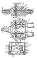
- Fig. 1 is a side, cross-sectional view of a molded plastic valve embodying the principles of the invention, along line 1-1 of Fig. 2,
- Fig. 2 is a plan view partially broken-away and partially in cross-section of the valve of Fig. 1 along line 2-2 of Fig. 1,
- Fig. 3 is a view taken in the direction of arrows 3-3 of Fig. 1,
- Fig. 4 is an end view, partially in cross-section, of an alternate embodiment of the invention showing in particular an alternate arrangement of the passages in the valve housing and in the reciprocable slide member,
- Figs. 5 and 6 are enlarged cross-sectional views of the reciprocable slide member and laminated seal of the invention along line 5-5 of Fig. 3 which illustrate the ability of the seal to compensate for differences in the width of the slide recess,
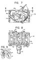
- Fig. 7 is a vertical cross-section of an alternate rotary form of valve incorporating the features of the invention,
- Fig. 8 is a plan view, partially, cut along line 8-8 of Fig. 7 of this alternate valve and
- Fig. 9 is a fragmentary illustration of the rotary slide member of Figs. 7 and 8 and the adjacent housing, juxtaposed to show the tab stop and recess means therefor of the invention.
- Referring now to the drawings and initially to Figs. 1 to 3 thereof a valve (10) includes a one-piece housing (11) and a moveable slide member (12) which are each molded of a suitable plastic material, by the use of injection molding techniques. Housing (11) has two tubular inlet connections (13 and 14) which are each threaded to a plastic tubing (16 and 17), respectively. One of the uses of the valve (10) is in conjunction with oxygenation/suctioning systems which permit the alternate oxygenating of the lungs of a patient and the removal of fluid therefrom by suction. Accordingly and for illustrative purposes, tubular member (16) may be for example connected to a source of suction and member (17) connected to a source of oxygen.
- The housing (11) includes passages (13a and 14a), respectively, which are in alignment with passages (13b, 14b). The latter are connected with a chamber (18) which is connected to a single cylindrical outlet (19). Outlet (19) is internally recessed at (19a) to receive the end of a catheter (20) whose distal end (not shown) may be inserted into the lungs of a patient for oxygenation/suctioning treatment.
- Between the inner ends of passages (13a, 14a and 13b, 14b) housing (11) defines a generally rectangular slot or recess (21) which receives the slide member (12) for reciprocal movement therein. The lateral ends of slide member (12) have been formed as cylindrical guide sections or posts (12a and 12b) which are received within mating cylindrical end sections (21a, 21b) of housing recess (21). The inner ends of post sections (12a and 12b) define two laterally spaced recesses (12c and 12d) which receive coiled compression springs (22), the opposite ends of these springs resting upon the bottom surface of recess (21).
- Slide member (12) can be depressed by the therapist or doctor administering the oxygenation/suctioning treatment by pressing down with the thumb or a forefinger against the upper curved flange (12e) of the slide member, the inner portion of which serves to limit inward movement of the slide member into recess (21). When such downward pressure is released, springs (22) will return the slide member (12) to the position shown in the figures, which in the illustrated embodiment is the oxygenation position. Slide member (12) defines a generally elliptical or elongated aperture (12f) which in the full outer position shown in Figs. 1 and 3 becomes aligned with the tube (17) connected to the oxygen source, while as best seen in Fig. 3 when slide member (12) is depressed within recess (21), the elliptical aperture (12b) is out of alignment with passageway (14a) (oxygen) and is brought into alignment with passageway (13a) (suction).
- Referring now to Figs. 5 and 6, it will be seen that slide member (12) has been formed to have an integral leaf spring tab (23) which normally and resiliently projects from a lateral surface of the slide member. Housing (11) has been formed with a corresponding recess (24) which receives tab (23) when the slide member (12) has been inserted into housing recess (21) for a distance sufficient to permit tab (23) to spring outwardly and into recess (24). When this has occurred, tab (23) acts as a stop, adapted to bear against the upper edge of recess (24) to prevent movement of slide member (12) outwardly of the recess beyond the position shown in Figs. 5 and 6. It will be understood that when the slide member (12) is further depressed into the recess and into its alternate suction position, tab (23) will be urged out of engagement with recess (24) and will return into such engagement to limit outward movement of slide member (12) when the parts have re-assumed the position of Figs. 5 and 6.
- In accordance with a critical aspect of the present invention, it will be seen that one side of slide member (12) defines a generally rectangular recess (26) and that within such recess a laminated sealing member (27) is mounted and affixed by using, for example, a suitable adhesive. Sealing member (27) consists of two layers, adhesively bonded together, the outermost layer (28) facing passages (13b and 14b) comprising a layer of low friction plastic material such as polytetrafluorethylene while the inner layer (29) within recess (26) is resilient and may, for example, be of silicone rubber. The laminated sealing member (27) extends peripherally around elliptical aperture (12f) in slide member (12). It will be seen and understood (see Fig. 5) that surface (12g) of slide member (12) and surface (26a) within recess (26) are planar and parallel and that laminated sealing member (27), including low friction sheet layer (28) is planar as well and parallel to these surfaces of slide member (12). In fact the outer surface of sheet layer (28) facing the orifice ends of passages (13b and 14b) may be perceived as a projection of the surface (12g) of slide member (12), but resiliently and movably backed up by inner layer (29).
- The unique qualities of laminated sealing member (27) to effect sealing of the elliptical passage (12d) in the slide member (12) with respect to passages (13b and 14b), and also with respect to passages (13a and 14a), may be seen in Figs. 5 and 6. Note the differences in dimension between the relatively narrow gap (21ʹ) shown in Fig. 5 and the relatively wider gap (21ʺ) shown in Fig. 6 which occurs between the surface (12g) of the slide member and the opposing or facing surface (11a) of the housing. These differences in width may in an actual molded valve configuration represent about one thenth(0,1)of a millimeter, a fairly typical working tolerance for injection molded plastic valves of this type. Thus the relatively smaller gap (21ʹ) (Fig. 5) causes the resilient layer (29) of sealing member (27) to be more greatly compressed than in the configuration of Fig. 6. However, since resilient layer (29) is constantly in compression, in both configurations it operates to force the low friction sheet layer (28) facing passages (13b and 14b) into sealing engagement with the orifice ends of passages (13b and 14b). Conversely, the resilient thrust of layer (29) also acts to force surface (12h) facing passages (13a and 14a) into sealing engagement with the orifice ends of these passages, thereby effecting a complete seal between both sides of the slide member and the passages in the adjacent housing.
- In accordance with another aspect of the present invention, the valve (10) incorporates a venting system which is best seen in connection with Fig. 2. Each of passages (13a) (suction) and (14a) (oxygen) includes, respectively, a vent passage (30, 31) which further include check valves (32, 33) to control venting of passages (13a, 14a) through vent orifices (34, 35). Check valves (32 and 33) may for example be of a slitted diaphragm type and will each be set to open whenever a preselected pressure differential exists with respect to opposite sides of the diaphragm. Accordingly, should a blockage occur in a catheter during the suctioning mode, air would be admitted through check valve (32) into passage (13a) as soon as a requisite pressure differential exists between the reduced pressure in passage (13a) and atmospheric pressure.
- Likewise, should an oxygen pressure surge, which could be very harmful to a patient, particularly an infant, whose lungs are being oxygenated, occur in line (14a), oxygen would be vented through valve (33) to the atmosphere to relieve the pressure surge.
- The check valve (33) has one other useful function. The slitted diaphragm construction will permit the introduction therethrough of a needle for injecting a sterile saline solution for lavage. The ability of the valve (10) quickly and easily to alternate between suction and oxygenation modes permits such saline solution to break up mucous or other blockages from the lungs encountered during suctioning by lavage which will be simultaneously administered with oxygen until suction flow is reestablished and the lungs are completely clear.
- It will be noted that passages (30, 31) and check valves (32, 33) are positioned relative to slide member (12) and housing recess (21) so that any bacterial contamination from member (12) or recess (21) cannot issue from vent orifices (34 or 35) when check valves (32, 33) are open. Thus, suction line (ʹ13a) leading to the suction pump exhaust venting system (not shown) remains free from contamination. Similarly, if oxygen is vented to atmosphere through valve (33) and vent orifice (35), the surrounding environment remains uncontaminated. These are very important health considerations particularly to those personnel present during administration of the oxygenation/suctioning procedure.
- Fig. 4 illustrates a variation of the valve configuration disclosed in Figs. 1
bo 3. Parts which are the same have been designated by the same reference numerals. Accordingly, valve housing (11) has been formed to have slide recess (21) therein which receives slide member (12ʹ). In the configuration of Fig. 4, it will be seen that oxygen passage (13aʹ) is located above suction passage (14aʹ) and not side-by-side as in the previous embodiment. Consequently, aperture (12fʹ) in the slide member is vertically oriented, as is laminated sealing member (27ʹ). Otherwise, the operation and function of the valve configuration of Fig. 4 is the same as that described in connection with Figs. 1 to 3 and Figs. 5 and 6. - Referring now to Figs. 7 to 9, there is shown an alternate rotary valve (40) constructed according to the principles of the present invention. Valve (40) includes a plastic valve housing (41) molded in two parts (41a and 41b), the housing having separate inlets (42, 43), which may be connected to suction and oxygen, respectively, and a single outlet (44) to be connected to a catheter (45). Passages (42a, 43a) are formed within housing (41) and lead to a generally semi-circular recess (46) which receives a otary slide member (47) therein. The latter includes an integral resilient tab (48) the upper curved end (48a) of which is adapted to be received and to snap into a mating recess (49) (Fig. 9) in the valve housing (41) when the parts are assembled.
- The slide member (47) has been formed with outer flanges (47a, 47b) each of which can be alternately depressed by the therapist or doctor to rotate member (47) into the oxygenation or suctioning positions. Flanges (47a and 47b) will abut the housing (41) to define these two operational positions. Rotation of slide member (47) is about the curved end portion (48a) of tab (48) and correspondingly curved portion of recess (49).
- Slide member (47) defines an aperture (47c) therein which will register with one or the other of passages (42a and 43a), respectively, when member (47) assumes its alternate positions. Accordingly and by this means alternate fluid connection can be made of inlets (42 and 43) to outlet (44). Slide member (47) further defines a recess (47d) which receives a laminated sealing member (50) whose periphery includes the curved section (50a) and straight peripheral sides (50b) through (50e). Sealing member (50) is a bonded laminate of two layers, i.e. a resilient backing layer (51), adhesively mounted in recess (47d), and a low friction sheet layer (52), which faces the inner orifice end of outlet (44). The operation of laminated sealing member (50) is the same as described in respect of the sealing member (27) of Figs. 1 through 6. It will therefore be understood that the combination of constant resilient force applied by resilient backing layer (51) acting upon the low friction surface of sheet layer (52) produces a highly efficient sealing of both sides of slide member (47) with respect to the orifice ends of the passages through the valve (40), and that sealing member (50) is capable of compensating for the fairly large molding tolerances which occur between the respective widths of recess (46) and the rotary slide member (47).
- Valve (40) also includes the non-contaminating vent system described in connection with the first embodiment. For this purpose, vent orifices (53, 53) and slitted diaphragm check valves (55, 56) are illustrated in Fig. 8. Additionally, valve (40) is provided with a lavage port (57) and a passage (58) through which a needle may be inserted to inject a sterile saline solution into the oxygen passage (42a). The lavage procedure has been described in connection with the embodiment of Figs. 1 through 6. It will be noted that lavage passage (58) is very narrow but sufficiently wide to admit a needle and consequently when oxygen is flowing in passage (42a) and passage (58) is not in use, ambiant air will be asperated into this passage by the venturi effect produced by the flow of oxygen past the inner end of passage (58).
- The various valve configurations disclosed herein are ideally of all molded plastic construction and lend themselves to high production and inexpensive cost. The laminated sealing member disclosed herein provides extremely efficient low-friction sealing and makes possible the use of these inexpensive molded plastic techniques.
Claims (7)
characterized in that said valve body (11; 41) is of precision molded construction and has an open valve cavity (21; 46) formed therein for the movable reception of said valve member (12; 47), that said oxygenation and suctioning port means (13, 14; 42, 43) open into said valve cavity at one side, and said catheterization port means (19; 44) opens into said valve cavity at the other side, that said valve member is of precision molded construction and has a cross sectional configuration closely conforming to that of said valve cavity while being freely bi-directionally movable therein with at least a minimum positive clearance, that said valve member has an open recess (26; 47d) of predetermined depth, less than the thickness of said valve member, and formed in at least one side thereof, that a resilient valve seal member (27; 47) is received in said recess, projects outward therefrom and has an outer surface (28; 52) of low friction material, that said resilient seal member has a thickness greater than the depth of said recess such that, within normal precision molding tolerance limits of said valve cavity and said valve member, said seal member will be held under at least some compression within said recess (26; 47d), that said valve member and said seal member have passage means (12f, 47e) therein, within the area of said recess, for alternatively connecting said oxygenation or suctioning port means with said catheterization port means, and that said valve member and said valve body have cooperating limit stop means (12e; 47a, 47b) for limiting the bi-directional movements of the valve member and defining said limit positions such that said seal-receiving recess and said seal extend over an area of said valve member such that at least a portion of said seal is positioned opposite said oxygenation and suctioning port means in either limit position of said valve member.
characterized in that said valve body (11; 41) and valve member (12; 47) are of precision molded construction to tolerances of approximately plus or minus 0,1 mm, that said valve member is of a relatively thin, flat cross sectional configuration, that said valve body has a valve receiving cavity (21; 46) therein of relatively thin, flat cross sectional configuaration adapted for the reception of said valve member (12; 47),that said valve member and said cavity are so dimensioned that, in all instances, a positive clearance (21ʹ; 21ʺ) will exist between the valve member and the walls of said cavity, that valve port means (13, 14; 42a, 43a; 19; 44) are provided in said valve body (11; 41) communicating with said cavity in opposite walls thereof, that said valve member (12; 47) has valve passage means (12f; 47c) operable upon predetermined positioning of said valve member to connect certain of said valve port means and to block certain other port means, that said valve member, in the region of said valve passage means, has a recess (26; 47d) of substantially greater depth than the thickness of said positive clearance, that a resilient seal member (27; 47) is received in said recess having a thickness at least slightly greater than the combined thickness of said positive clearance and the depth of said recess, whereby said seal member is maintained under at least a slight compression, that said seal member comprises a composite material formed principally of resilient material (29; 51) and having an outer surface (28; 52) of low friction material, and that said seal member forms a seal with one wall of said cavity and urging the opposite side of said valve member toward the opposite wall of said cavity.
Applications Claiming Priority (2)
| Application Number | Priority Date | Filing Date | Title |
|---|---|---|---|
| US06/854,829 US4705073A (en) | 1986-04-23 | 1986-04-23 | Molded plastic gate valve and sealing means therefor |
| US854829 | 1986-04-23 |
Publications (2)
| Publication Number | Publication Date |
|---|---|
| EP0242871A2 true EP0242871A2 (en) | 1987-10-28 |
| EP0242871A3 EP0242871A3 (en) | 1989-03-22 |
Family
ID=25319622
Family Applications (1)
| Application Number | Title | Priority Date | Filing Date |
|---|---|---|---|
| EP19870105909 Withdrawn EP0242871A3 (en) | 1986-04-23 | 1987-04-22 | Molded plastic valve and sealing means therefor |
Country Status (2)
| Country | Link |
|---|---|
| US (1) | US4705073A (en) |
| EP (1) | EP0242871A3 (en) |
Cited By (3)
| Publication number | Priority date | Publication date | Assignee | Title |
|---|---|---|---|---|
| EP0347026A2 (en) * | 1988-04-19 | 1989-12-20 | Ventech Healthcare Corporation Inc. | Valve for an endotracheal tube used for ventilation and aspiration |
| FR2759915A1 (en) * | 1997-02-27 | 1998-08-28 | Concept Medical Service | Suction controller for use in medicine |
| DE102009010131A1 (en) | 2008-03-11 | 2009-09-17 | Luk Lamellen Und Kupplungsbau Beteiligungs Kg | Longitudinal slide valve i.e. piston slide valve for hydraulic applications i.e. hydraulic controller, has longitudinal slide implemented as flat slide and movably accommodated in retaining area that is recessed in slide retaining body |
Families Citing this family (32)
| Publication number | Priority date | Publication date | Assignee | Title |
|---|---|---|---|---|
| DE58906330D1 (en) * | 1988-03-09 | 1994-01-20 | Blaschke Pumpen Filteranlagen | Device for ventilation of protective suits. |
| JPH01144058U (en) * | 1988-03-25 | 1989-10-03 | ||
| GB8819514D0 (en) * | 1988-08-17 | 1988-09-21 | Neotronics Technology Plc | Resuscitator valve |
| US5207641A (en) * | 1989-05-15 | 1993-05-04 | Bird Medical International Inc. | Medical rotary valve having aspiration, insufflation and an intermediate flushing positions |
| US5181908A (en) * | 1990-12-07 | 1993-01-26 | Smiths Industries Medical Systems Inc. | Method and apparatus for lavaging with oxygenated irrigating fluid while suctioning |
| US5224929A (en) * | 1990-12-21 | 1993-07-06 | C. R. Bard, Inc. | Irrigation/aspiration cannula and valve assembly |
| US5279549A (en) * | 1991-01-04 | 1994-01-18 | Sherwood Medical Company | Closed ventilation and suction catheter system |
| DE4120609C1 (en) * | 1991-06-20 | 1993-02-11 | Wiest, Peter P., Dipl.-Ing., 1000 Berlin, De | Gas connector for insufflation appts. - has pressure reducer, safety valve, pressure indicator and gas outlet union with magnetic valve |
| US5303735A (en) * | 1991-12-04 | 1994-04-19 | Ryder International Corporation | Valve assembly |
| US5722949A (en) * | 1994-08-26 | 1998-03-03 | Sanese Medical Corporation | Fluid supply and suction apparatus and method |
| US5586974A (en) * | 1995-04-25 | 1996-12-24 | Olympus America, Inc. | Continuously adjustable high flow insufflator valve |
| AU6686796A (en) * | 1995-08-02 | 1997-02-26 | Parker-Hannifin Corporation | Lockout valve |
| US6227200B1 (en) | 1998-09-21 | 2001-05-08 | Ballard Medical Products | Respiratory suction catheter apparatus |
| US7021313B1 (en) | 1998-09-21 | 2006-04-04 | Ballard Medical Products | Respiratory suction catheter apparatus with improved valve and collar |
| US6427691B1 (en) * | 1999-07-09 | 2002-08-06 | Walter Jinotti | Medical valve |
| US7152603B1 (en) | 1999-12-13 | 2006-12-26 | Kimberly-Clark Worldwide, Inc. | Endotracheal catheter and manifold assembly with improved valve |
| US6543451B1 (en) | 1999-12-23 | 2003-04-08 | Kimberly-Clark Worldwide, Inc. | Endotracheal catheter and manifold assembly with improved seal and valve |
| DE10030584A1 (en) * | 2000-06-21 | 2002-01-03 | Gneuss Kunststofftechnik Gmbh | Reusable rotary slide valve for the distribution of high-molecular polymer-plastic melts |
| US6769430B1 (en) | 2000-10-31 | 2004-08-03 | Kimberly-Clark Worldwide, Inc. | Heat and moisture exchanger adaptor for closed suction catheter assembly and system containing the same |
| US6729326B1 (en) * | 2000-11-27 | 2004-05-04 | Sorenson Medical, Inc. | Neonatal valved manifold |
| IL145461A (en) * | 2001-09-16 | 2006-09-05 | Alyn Woldenberg Family Hospita | Inexsufflator |
| US6588427B1 (en) | 2002-02-25 | 2003-07-08 | Kimberly-Clark Worldwide, Inc. | Heat and moisture exchanger adapter to closed suction catheter assembly and system having improved catheter cleaning |
| US7137974B2 (en) * | 2002-07-26 | 2006-11-21 | Almasian Joseph M | Sterile connector |
| US7644722B2 (en) * | 2003-03-04 | 2010-01-12 | Wolfe Tory Medical, Inc. | Medical valve and method to monitor intra-abdominal pressure |
| US20070255167A1 (en) * | 2004-03-01 | 2007-11-01 | Wolfe Tory Medical, Inc. | Apparatus for monitoring intra-abdominal pressure |
| US7112177B2 (en) * | 2003-03-04 | 2006-09-26 | Wolfe Tory Medical, Inc. | Apparatus for monitoring intra-abdominal pressure |
| US8052671B2 (en) * | 2004-10-11 | 2011-11-08 | Abviser Medical, Llc | Intra-abdominal pressure monitoring device and method |
| US20070186928A1 (en) * | 2005-09-26 | 2007-08-16 | Be Eri Eliezer | Combined ventilator inexsufflator |
| US20070199566A1 (en) * | 2006-02-02 | 2007-08-30 | Be Eri Eliezer | Respiratory apparatus |
| DE102008025959B4 (en) * | 2008-05-30 | 2013-09-19 | Airbus Operations Gmbh | Device for connecting two pipe elements and a shutter in an aircraft air conditioning system |
| US20130030373A1 (en) * | 2011-07-29 | 2013-01-31 | Sfk Business Ventures, Llc | Angiocatheter System With Anti-Leak Features |
| DE102016106410A1 (en) * | 2016-04-07 | 2017-10-12 | Samson Aktiengesellschaft | Electropneumatic solenoid valve, impact valve member for an electropneumatic solenoid valve |
Citations (4)
| Publication number | Priority date | Publication date | Assignee | Title |
|---|---|---|---|---|
| DE2110855A1 (en) * | 1971-03-08 | 1972-09-28 | Rheinisches Metallwerk Gmbh | Valve spindle - with applied elastic lining |
| US4089506A (en) * | 1977-01-24 | 1978-05-16 | American Hospital Supply Corporation | Gate valve |
| US4193406A (en) * | 1978-09-18 | 1980-03-18 | Jinotti Walter J | Dual purpose catheter |
| GB2073851A (en) * | 1980-02-19 | 1981-10-21 | Ranco Inc | Water Flow Control Valve |
Family Cites Families (10)
| Publication number | Priority date | Publication date | Assignee | Title |
|---|---|---|---|---|
| DE946258C (en) * | 1950-07-12 | 1956-07-26 | Draegerwerk Ag | Respirator |
| US3035809A (en) * | 1960-03-18 | 1962-05-22 | Phillips Petroleum Co | Self-lubricating compressible slide gate |
| US3113757A (en) * | 1961-01-18 | 1963-12-10 | Nixon Phillip | Solenoid-operated gate valve |
| GB1150267A (en) * | 1966-06-08 | 1969-04-30 | Kinematics Ltd | Improvements in and relating to Sluice Valves. |
| US3570540A (en) * | 1969-12-11 | 1971-03-16 | Mine Safety Appliances Co | Piston operated slide valve |
| US3784158A (en) * | 1972-05-01 | 1974-01-08 | Coplastix Ltd | Fluid-flow control valves and sealing means therefor |
| US4019535A (en) * | 1973-05-31 | 1977-04-26 | Globe-Union Inc. | Material selector system |
| US3936031A (en) * | 1973-09-21 | 1976-02-03 | Alphamedics Mfg. Corporation | Self-contained vacuum aspirator |
| US4221307A (en) * | 1978-11-22 | 1980-09-09 | Salina Vortex Conveyor Corporation | Method and apparatus for material handling |
| US4595005A (en) * | 1984-02-08 | 1986-06-17 | Jinotti Walter J | Dual-purpose catheter |
-
1986
- 1986-04-23 US US06/854,829 patent/US4705073A/en not_active Expired - Fee Related
-
1987
- 1987-04-22 EP EP19870105909 patent/EP0242871A3/en not_active Withdrawn
Patent Citations (4)
| Publication number | Priority date | Publication date | Assignee | Title |
|---|---|---|---|---|
| DE2110855A1 (en) * | 1971-03-08 | 1972-09-28 | Rheinisches Metallwerk Gmbh | Valve spindle - with applied elastic lining |
| US4089506A (en) * | 1977-01-24 | 1978-05-16 | American Hospital Supply Corporation | Gate valve |
| US4193406A (en) * | 1978-09-18 | 1980-03-18 | Jinotti Walter J | Dual purpose catheter |
| GB2073851A (en) * | 1980-02-19 | 1981-10-21 | Ranco Inc | Water Flow Control Valve |
Cited By (4)
| Publication number | Priority date | Publication date | Assignee | Title |
|---|---|---|---|---|
| EP0347026A2 (en) * | 1988-04-19 | 1989-12-20 | Ventech Healthcare Corporation Inc. | Valve for an endotracheal tube used for ventilation and aspiration |
| EP0347026A3 (en) * | 1988-04-19 | 1990-07-18 | Ventech Healthcare Corporation Inc. | Valve for an endotracheal tube used for ventilation and aspiration |
| FR2759915A1 (en) * | 1997-02-27 | 1998-08-28 | Concept Medical Service | Suction controller for use in medicine |
| DE102009010131A1 (en) | 2008-03-11 | 2009-09-17 | Luk Lamellen Und Kupplungsbau Beteiligungs Kg | Longitudinal slide valve i.e. piston slide valve for hydraulic applications i.e. hydraulic controller, has longitudinal slide implemented as flat slide and movably accommodated in retaining area that is recessed in slide retaining body |
Also Published As
| Publication number | Publication date |
|---|---|
| US4705073A (en) | 1987-11-10 |
| EP0242871A3 (en) | 1989-03-22 |
Similar Documents
| Publication | Publication Date | Title |
|---|---|---|
| US4705073A (en) | Molded plastic gate valve and sealing means therefor | |
| US4712583A (en) | Precision passive flat-top valve for medication infusion system | |
| US5445141A (en) | Respiratory support system | |
| EP0781379B1 (en) | Engineered pumping segment | |
| US5353837A (en) | Quick-disconnect valve | |
| EP1839689B1 (en) | Cassette having elastomeric clamping ribs | |
| EP0492162B1 (en) | Irrigation/aspiration cannula | |
| EP0781402B1 (en) | Dome-shaped pressure vessel and method for optimizing same | |
| DK0643591T3 (en) | Peritoneal Dialysis Systems and Methods Using a Liquid Distribution and Pump Cartridge with Independent Air Insulation and Bo | |
| US5337780A (en) | Suction control valve | |
| US5647575A (en) | Volumetric shaft/valve | |
| US5006114A (en) | Medical valve assembly | |
| US5628306A (en) | Respiratory manifold with accessory access port | |
| EP0777832B1 (en) | Sliding flow controller having channel with variable size groove | |
| CA2354130C (en) | Fluid flow rate switching device | |
| US6886561B2 (en) | Respiratory valve | |
| EP2968900B1 (en) | Collapsible valve with internal dimples | |
| BR8606684A (en) | CASSETTE FOR SURGICAL IRRIGATION AND ASPIRATION, COMBINATION FOR SURGICAL IRRIGATION AND ASPIRATION AND MEDICAL INSTRUMENT CASSETTE | |
| CA2190098A1 (en) | Disposable fluid infusion pumping chamber cassette having a push button flow stop thereon | |
| KR950700087A (en) | Surgical Cassette | |
| US5191881A (en) | Insufflating/suctioning valve | |
| US5309904A (en) | Insufflating/suctioning valve | |
| US4064909A (en) | Slide valve apparatus | |
| EP0347026A2 (en) | Valve for an endotracheal tube used for ventilation and aspiration | |
| US4629158A (en) | Disposable male valve member |
Legal Events
| Date | Code | Title | Description |
|---|---|---|---|
| PUAI | Public reference made under article 153(3) epc to a published international application that has entered the european phase |
Free format text: ORIGINAL CODE: 0009012 |
|
| AK | Designated contracting states |
Kind code of ref document: A2 Designated state(s): AT BE CH DE ES FR GB GR IT LI LU NL SE |
|
| PUAL | Search report despatched |
Free format text: ORIGINAL CODE: 0009013 |
|
| AK | Designated contracting states |
Kind code of ref document: A3 Designated state(s): AT BE CH DE ES FR GB GR IT LI LU NL SE |
|
| STAA | Information on the status of an ep patent application or granted ep patent |
Free format text: STATUS: THE APPLICATION IS DEEMED TO BE WITHDRAWN |
|
| 18D | Application deemed to be withdrawn |
Effective date: 19890923 |
|
| RIN1 | Information on inventor provided before grant (corrected) |
Inventor name: BECK, BLAINE E. |