EP0242649A2 - Printing unit for a rotary printing machine - Google Patents
Printing unit for a rotary printing machine Download PDFInfo
- Publication number
- EP0242649A2 EP0242649A2 EP87104793A EP87104793A EP0242649A2 EP 0242649 A2 EP0242649 A2 EP 0242649A2 EP 87104793 A EP87104793 A EP 87104793A EP 87104793 A EP87104793 A EP 87104793A EP 0242649 A2 EP0242649 A2 EP 0242649A2
- Authority
- EP
- European Patent Office
- Prior art keywords
- blanket
- cylinder
- impression cylinder
- printing unit
- cylinders
- Prior art date
- Legal status (The legal status is an assumption and is not a legal conclusion. Google has not performed a legal analysis and makes no representation as to the accuracy of the status listed.)
- Granted
Links
Images


Classifications
-
- B—PERFORMING OPERATIONS; TRANSPORTING
- B41—PRINTING; LINING MACHINES; TYPEWRITERS; STAMPS
- B41F—PRINTING MACHINES OR PRESSES
- B41F7/00—Rotary lithographic machines
- B41F7/02—Rotary lithographic machines for offset printing
- B41F7/025—Multicolour printing or perfecting on sheets or on one or more webs, in one printing unit
Definitions
- the invention relates to a printing unit according to the preamble of claim 1.
- a printing unit is known from DE-AS 28 44 418.
- This printing unit it is possible to apply a double face print to a print carrier web or to selectively apply one face print from one of the two blanket cylinders during operation of the machine.
- a double-sized fixed common impression cylinder is used, on which two so-called simple large rubber blanket cylinders can be adjusted together or individually.
- Each of the blanket cylinders thus has two positions with respect to the common impression cylinder, namely an on and an off position.
- DE-AS 1 238 929 From DE-AS 1 238 929 it is known to provide three positions for a blanket cylinder in a conventional five-cylinder printing unit which comprises a common printing cylinder and two blanket cylinders, but this is not a printing unit for a so-called "flying plate change". , d. H. With this printing unit it is not possible to alternately position the blanket cylinders on the impression cylinder during operation.
- DE-GM 1 827 845 shows printing unit configurations (FIG. 3, FIG. 4) with which a print carrier web is either provided with a print on both sides or with a double print on one side.
- the object of the invention is to develop a printing unit of the type specified at the outset in such a way that it can be used in a variety of ways, ie that both double-sided printing (1/1), double face printing (2/0) and an impression (1/0 below / 1/0 above) is possible, whereby duplication should be avoided when printing on both sides (1/1).
- This object is achieved by applying the features of the characterizing part of claim 1 solved.
- the advantage of the solution according to the invention is that minimal adjustment options are required, since the printing cylinder is fixed in position, one of the blanket cylinders only has to have an on and off position and the other blanket cylinder has three positions according to the respective operating modes and that three or four operating modes are possible are.
- FIG. 1 to 10 schematically show the printing unit according to the invention in five operating modes.
- a simply large impression cylinder 1 is locally fixed with its central axis 1 ⁇ .
- Two blanket cylinders 2, 3 can be set on this impression cylinder 1.
- the blanket cylinder 2 or 3 can alternately be placed on the common impression cylinder 1 (FIGS. 2, 3), so that printing on the printing medium web 6, which is guided around the impression cylinder in a known manner, is printed on one side can (1/0 above or 1/0 below).
- the blanket cylinders 2 and 3 are each assigned plate cylinders 4, 5, which do not have to be pivoted during the individual changeover processes, but which can be lifted off the respective blanket cylinder for the plate change.
- a further mode of operation of the printing unit shown results from the fact that, as indicated in FIG. 1, the print carrier web is carried out between the two blanket cylinders 2, 3 placed against one another and is partly continued around the impression cylinder 1.
- the impression cylinder 1 and the blanket cylinder 2 are also placed against each other.
- the direction of rotation of the cylinders 1, 2, 3 is indicated by arrows in the respective operating modes. It is understood that in the version shown, a reversal of the direction of rotation is required at least for the lower blanket cylinder 3, when this is turned on the impression cylinder 1 in the direction of rotation shown.
- the individual position of the blanket cylinders 2, 3 for the operating modes mentioned is indicated by an apostrophe.
- the position 2 ⁇ indicates the storage position of the blanket cylinder 2 from the impression cylinder 1, while the position 2 ⁇ marks the position on the impression cylinder 1.
- the position 3 ⁇ means the position in which the blanket cylinder 3 is turned off by both the blanket cylinder 2 and the impression cylinder 1, i. H. in the case of the flying impression, a plate change can be carried out on the plate cylinder 5 in this position.
- the position 3 ′′′ indicates the position of the blanket cylinder 3 on the impression cylinder 1. At 3 ⁇ the blanket cylinder 3 is employed on the impression cylinder 1.
- an advantageous further development of the invention consists in that, in the printing unit according to the invention, the impression cylinder 1 can be covered with a rubber blanket 9 using a pit 8, so that a so-called re-offset on the underside of the print carrier web 6 in the perfecting mode (1/1) he follows. Furthermore, the use of a washing unit 7 attached to the impression cylinder 1 is advantageous. Perforating strips 14 can also be attached axially or circumferentially on the impression cylinder 1.
- FIG. 5 Blanket plate cylinder pair 11, 10 z. B. above a through the center 1 ⁇ of the impression cylinder 1 horizontal plane, and possibly a further blanket-plate cylinder pair 12, 13 is arranged below this level.
- the arrangement of the upper pair of cylinders 11, 12 is thus at an angle less than 180 ° to the negative abscissa whose coordinate intersection is assumed to be the center point 1 ⁇ , measured counterclockwise.
- the possible path guidance is indicated at 6 ⁇ .
- Fig. 4 on the print carrier web 6 ⁇ allows double printing. The triangles each indicate on which side of the print carrier web 6 or 6 ⁇ is printed.
- FIGS. 6 to 10 in particular for newspaper printing.
- Fig. 6 enables 1/1 printing, it being possible to work on the face side with “flying plate change” and the counterprint is single-colored when the impression cylinder 1 is covered with a rubber blanket.
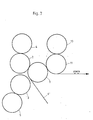
- Fig. 7 also enables a 2/0 print with "flying plate change”.
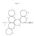
- Fig. 8 for the web 6 ⁇ , a 1/1 pressure and for the web 6 ⁇ a 1/0 pressure can be achieved.
- Fig. 10 offers 2/1 and Fig. 9 a 3/0 print.
- Fig. 7 is advantageous for local editions with a colored impression, eg. B. with underlined headings.
Abstract
Bei einem Fünfzylinderdruckwerk für 1/1, 2/0 und Eindruck 1/0 unten/1/0 oben wird ein Gummituchzylinder 3 mit drei Positionen verwendet. Bei einer sind die beiden Gummituchzylinder 2, 3 bei der anderen der Gummituchzylinder 3 und ein feststehender Gegendruckzylinder 1 aneinander angestellt, während bei der dritten Position der Gummituchzylinder 3 sowohl von dem Gummituchzylinder 2 als auch von dem Gegendruckzylinder 1 abgestellt ist. Während des 1/1 Druckes wird die Druckträgerbahn 6 sowohl zwischen den aneinander angestellten Gummituchzylinder 2, 3 als auch zwischen den aneinander angestellten Gummituchzylinder 2 und Gegendruckzylinder 1 geführt, sodaß ein Dublieren vermieden wird. An den Gegendruckzylinder 1 kann eine Waschvorrichtung 7 angeordnet werden und an seinem Umfang oder in Achsrichtung können Perforierstreifen 14 fixiert werden. 
Description
Die Erfindung betrifft ein Druckwerk nach dem Oberbegriff des Anspruchs 1. Ein derartiges Druckwerk ist aus der DE-AS 28 44 418 bekannt. Mit diesem Druckwerk ist es möglich, auf eine Druckträgerbahn zweifachen Schöndruck oder während des Betriebes der Maschine wahlweise von einem der beiden Gummituchzylinder einen Schöndruck aufzubringen. Dabei wird ein doppelgroßer feststehender gemeinsamer Gegendruckzylinder verwendet, an den zwei sogenannte einfache große Gummituchzylinder gemeinsam oder einzeln anstellbar sind. Jeder der Gummituchzylinder weist somit bezogen auf den gemeinsamen Gegendruckzylinder zwei Positionen auf, nämlich eine Anstell- und eine Abstellposition.The invention relates to a printing unit according to the preamble of
Aus der DE-AS 1 238 929 ist es zwar bekannt, in einem herkömmlichen Fünfzylinderdruckwerk, das einen gemeinsamen Druckzylinder und zwei Gummituchzylinder umfaßt, für einen Gummituchzylinder drei Positionen vorzusehen, jedoch handelt es sich hier nicht um ein Druckwerk für einen sogenannten "fliegenden Plattenwechsel", d. h. es ist mit diesem Druckwerk nicht möglich, während des Betriebes wechselweise die Gummituchzylinder an den Gegendruckzylinder anzustellen. Schließlich zeigt das DE-GM 1 827 845 Druckwerkkonfigurationen (Fig. 3, Fig. 4), mit denen eine Druckträgerbahn entweder beidseitig mit einem Druck oder auf einer Seite mit einem zweifachen Druck versehen werden.From DE-AS 1 238 929 it is known to provide three positions for a blanket cylinder in a conventional five-cylinder printing unit which comprises a common printing cylinder and two blanket cylinders, but this is not a printing unit for a so-called "flying plate change". , d. H. With this printing unit it is not possible to alternately position the blanket cylinders on the impression cylinder during operation. Finally, DE-GM 1 827 845 shows printing unit configurations (FIG. 3, FIG. 4) with which a print carrier web is either provided with a print on both sides or with a double print on one side.
Aufgabe der Erfindung ist es ein Druckwerk der eingangs spezifizierten Gattung so weiterzubilden, daß es vielseitig einsetzbar ist, d. h. daß sowohl ein beidseitiger Druck (1/1), ein zweifacher Schöndruck (2/0) als auch ein Eindruck (1/0 unten/1/0 oben) möglich ist, wobei ein Dublieren bei einem beidseitigen Druck (1/1) vermieden werden soll. Diese Aufgabe wird durch die Anwendung der Merkmale des kennzeichnenden Teils des Anspruch 1 gelöst. Der Vorteil der erfindungsgemäßen Lösung besteht darin, daß minimale Verstellmöglichkeiten erforderlich sind, da der Druckzylinder festpositioniert ist, einer der Gummituchzylinder lediglich eine An- und Abstellposition aufweisen muß und der andere Gummituchzylinder entsprechend den jeweiligen Betriebsweisen drei Stellpositionen aufweist und daß drei bzw. vier Betriebsweisen möglich sind.The object of the invention is to develop a printing unit of the type specified at the outset in such a way that it can be used in a variety of ways, ie that both double-sided printing (1/1), double face printing (2/0) and an impression (1/0 below / 1/0 above) is possible, whereby duplication should be avoided when printing on both sides (1/1). This object is achieved by applying the features of the characterizing part of
Weiterbildungen der Erfindung ergeben sich aus den Unteransprüchen und aus der Beschreibung in Verbindung mit der Zeichnung. Diese zeigen in Fig. 1 bis 10 schematisch das erfindungsgemäße Druckwerk in fünf Betriebsarten. Ein einfach großer Gegendruckzylinder 1 ist mit seiner Mittelachse 1ʹ örtlich festpositioniert. An diesen Gegendruckzylinder 1 sind zwei Gummituchzylinder 2, 3 anstellbar. Während des Betriebes können bei einem sogenannten "fliegenden Plattenwechsel" abwechselnd der Gummituchzylinder 2 oder 3 an den gemeinsamen Gegendruckzylinder 1 angestellt werden, (Fig. 2, 3), so daß auf einer Seite der in bekannter Weise um den Gegendruckzylinder geführten Druckträgerbahn 6 gedruckt werden kann (1/0 oben oder 1/0 unten). Den Gummituchzylindern 2 und 3 sind jeweils Plattenzylinder 4, 5 zugeordnet, die während der einzelnen Umstellvorgänge nicht mitverschwenkt werden müssen, die jedoch für den Plattenwechsel vom jeweiligen Gummituchzylinder abhebbar sind.Further developments of the invention result from the subclaims and from the description in connection with the drawing. 1 to 10 schematically show the printing unit according to the invention in five operating modes. A simply
Eine weitere Betriebsweise des dargestellten Druckwerks ergibt sich dadurch, daß, wie Fig. 1 angedeutet, die Druckträgerbahn zwischen den beiden aneinander angestellten Gummituchzylindern 2, 3 durchgeführt und teilweise um den Gegendruckzylinder 1 weitergeführt wird. Dabei sind auch der Gegendruckzylinder 1 und der Gummituchzylinder 2 aneinander angestellt. Die Drehrichtung der Zylinder 1, 2, 3 ist bei den jeweiligen Betriebsarten durch Pfeile angedeutet. Es versteht sich, daß in der dargestellten Version zumindest für den unteren Gummituchzylinder 3 eine Drehrichtungsumkehr erforderlich ist, wenn dieser bei der dargestellten Drehrichtung des Gegendruckzylinders 1 an diesen angestellt wird.A further mode of operation of the printing unit shown results from the fact that, as indicated in FIG. 1, the print carrier web is carried out between the two
Bei der dargestellten Betriebsweise für Schön- und Widerdruck (1/1) ist die Gefahr eines Dublierens vermieden, da die Druckträgerbahn 6 sowohl zwischen den Gummituchzylindern 2, 3 als auch zwischen dem Gummituchzylinder 2 und dem Gegendruckzylinder 1 sicher geführt wird.In the illustrated mode of printing for perfecting (1/1), the risk of duplication is avoided, since the
Die einzelne Stellposition der Gummituchzylinder 2, 3 für die erwähnten Betriebsarten, ist jeweils durch einen Apostroph angedeutet. Die Position 2ʹ deutet die Abstellposition des Gummituchzylinders 2 von dem Gegendruckzylinder 1 an, während die Position 2ʺ die Stellung an dem Gegendruckzylinder 1 markiert. Bei dem Gummituchzylinder 3 bedeutet die Position 3ʺ die Stellung, bei der der Gummituchzylinder 3 sowohl von dem Gummituchzylinder 2 als auch von dem Gegendruckzylinder 1 abgestellt ist, d. h. beim fliegenden Abdruck kann in dieser Position ein Plattenwechsel an dem Plattenzylinder 5 vorgenommen werden. Die Position 3‴ deutet die Anstellposition des Gummituchzylinders 3 an den Gegendruckzylinder 1 an. Bei 3ʹ ist der Gummituchzylinder 3 an den Gegendruckzylinder 1 angestellt.The individual position of the
Eine vorteilhafte Weiterbildung der Erfindung besteht darin, daß bei dem erfindungsgemäßen Druckwerk der Gegendruckzylinder 1 unter Verwendung einer Grube 8 mit einem Gummituch 9 bespannt werden kann, wodurch ein sogenanntes Nachoffseten an der Unterseite der Druckträgerbahn 6 bei der Schön- und Widerdruckbetriebsweise (1/1) erfolgt. Des weiteren ist die Verwendung eines an den Gegendruckzylinder 1 angestellten Waschwerkes 7 von Vorteil. Auch können auf dem Gegendruckzylinder 1 axial oder in Umfangsrichtung Perforierstreifen 14 angebracht werden.An advantageous further development of the invention consists in that, in the printing unit according to the invention, the
Eine weitere Ausbildungsmöglichkeit des Druckwerkes besteht darin, daß zumindestens ein weiteres (Fig. 5) Gummituch-Plattenzylinderpaar 11, 10 z. B. oberhalb einer durch den Mittelpunkt 1ʹ des Gegendruckzylinders 1 verlaufenden horizontalen Ebene, und ggf. ein weiteres Gummituch-Plattenzylinderpaar 12, 13 unterhalb dieser Ebene angeordnet wird. Die Anordnung des oberen Zylinderpaars 11, 12 liegt somit in einem Winkel kleiner als 180° zur negativen Abszisse deren Koordinatenschnittpunkt im Mittelpunkt 1ʹ angenommen wird, gegen den Uhrzeigersinn gemessen. Die hierbei mögliche Bahnführung ist bei 6ʹ angedeutet. Schließlich ermöglicht Fig. 4 auf der Druckträgerbahn 6ʹ einen zweifachen Schöndruck. Die Dreiecke zeigen jeweils an, auf welcher Seite der Druckträgerbahn 6 bzw. 6ʹ gedruckt wird.Another training option for the printing unit is that at least one further (FIG. 5) Blanket
Weitere vorteilhafte Ausgestaltungen ergeben sich aus den Fig. 6 bis 10, insbesondere für den Zeitungsdruck. Fig. 6 ermöglicht einen 1/1 Druck, wobei auf der Schöndruckseite mit "fliegendem Plattenwechsel" gearbeitet werden kann und der Widerdruck bei mit einem Gummituch belegtem Gegendruckzylinder 1 einfarbig ist. Fig. 7 ermöglicht ebenfalls bei "fliegendem Plattenwechsel" einen 2/0 Druck. Nach Fig. 8 ist für die Bahn 6ʹ, ein 1/1 Druck und für die Bahn 6ʺ ein 1/0 Druck zu erreichen. Fig. 10 bietet einen 2/1 und Fig. 9 einen 3/0 Druck.Further advantageous refinements emerge from FIGS. 6 to 10, in particular for newspaper printing. Fig. 6 enables 1/1 printing, it being possible to work on the face side with "flying plate change" and the counterprint is single-colored when the
Fig. 7 ist vorteilhaft bei Lokalausgaben mit einem farbigen Eindruck, z. B. mit unterstrichenen Oberschriften.Fig. 7 is advantageous for local editions with a colored impression, eg. B. with underlined headings.
Claims (10)
dadurch gekennzeichnet,
daß der andere Gummituchzylinder (3) drei Positionen (3ʹ, 3ʺ, 3‴) einnehmen kann, zur Anstellung an den gemeinsamen Gegendruckzylinder (1) oder zur Anstellung an den einen Gummituchzylinder (2) oder in eine von beiden Zylindern (1, 2) getrennte Position, wobei die Druckträgerbahn (6) zwischen den beiden Gummituchzylindern (2, 3) und zwischen dem einen Gummituchzylinder (2) und dem Gegendruckzylinder (1) hindurchführbar ist, wenn die beiden Gummituchzylinder (2, 3) aneinander und der eine Gummituchzylinder (2) an den gemeinsamen Gegendruckzylinder (1) angestellt sind.1. Printing unit for a web-fed rotary printing press with a stationary impression cylinder, around which a printing carrier web is guided and to which at least two blanket cylinders a rubber blanket cylinder can optionally be adjusted simultaneously or during operation, a blanket cylinder having a starting and a parking position with respect to the common impression cylinder,
characterized,
that the other blanket cylinder (3) can take up three positions (3ʹ, 3ʺ, 3 ‴), for employment on the common impression cylinder (1) or for employment on the one blanket cylinder (2) or in one of both cylinders (1, 2) Separate position, the print carrier web (6) being able to be passed between the two blanket cylinders (2, 3) and between the one blanket cylinder (2) and the impression cylinder (1) when the two blanket cylinders (2, 3) are in contact with one another and the one blanket cylinder ( 2) are employed on the common impression cylinder (1).
dadurch gekennzeichnet,
daß der Gegendruckzylinder (1) den gleichen Durchmesser, wie die beiden Gummituchzylinder (2, 3) aufweist. 3. Druckwerk nach Anspruch 1 oder 2,
dadurch gekennzeichnet,
daß an den Gegendruckzylinder (1) ein Waschwerk (7) angestellt ist.2. Printing unit according to claim 11,
characterized,
that the impression cylinder (1) has the same diameter as the two blanket cylinders (2, 3). 3. Printing unit according to claim 1 or 2,
characterized,
that a washer (7) is employed on the impression cylinder (1).
daß der Gegendruckzylinder (1) mit einem Gummituch (9) bespannt ist.4. Printing unit according to one of the preceding claims, characterized in
that the impression cylinder (1) is covered with a rubber blanket (9).
daß auf dem Gegendruckzylinder (1) in Umfangsrichtung oder achsparallel laufende Perforierstreifen (14) angeordnet sind.5. Printing unit according to one of the preceding claims, characterized in
that on the impression cylinder (1) in the circumferential direction or axially parallel perforating strips (14) are arranged.
dadurch gekennzeichnet,
daß an den Gegendruckzylindern (1) mindestens ein weiteres Gummituch-Plattenzylinderpaar (11, 10, 12, 13) anstellbar ist.6. Printing unit according to one of the preceding claims,
characterized,
that at least one further pair of blanket-plate cylinders (11, 10, 12, 13) can be set on the impression cylinders (1).
dadurch gekennzeichnet,
daß der Mittelpunkt des Gummituchzylinders (11) eines Gummituch-Plattenzylinderpaares (11, 10) oberhalb einer durch den Mittelpunkt (1ʹ) des Gegendruckzylinders (1) verlaufenden horizontalen Ebene angeordnet ist.7. Printing unit according to claim 6,
characterized,
that the center of the blanket cylinder (11) of a pair of blanket-plate cylinders (11, 10) is arranged above a horizontal plane running through the center (1ʹ) of the impression cylinder (1).
Applications Claiming Priority (2)
| Application Number | Priority Date | Filing Date | Title |
|---|---|---|---|
| DE3614030 | 1986-04-25 | ||
| DE19863614030 DE3614030A1 (en) | 1986-04-25 | 1986-04-25 | PRINTER FOR A ROLL ROTATION PRINTING MACHINE |
Publications (3)
| Publication Number | Publication Date |
|---|---|
| EP0242649A2 true EP0242649A2 (en) | 1987-10-28 |
| EP0242649A3 EP0242649A3 (en) | 1989-10-11 |
| EP0242649B1 EP0242649B1 (en) | 1992-03-11 |
Family
ID=6299525
Family Applications (1)
| Application Number | Title | Priority Date | Filing Date |
|---|---|---|---|
| EP87104793A Expired - Lifetime EP0242649B1 (en) | 1986-04-25 | 1987-04-01 | Printing unit for a rotary printing machine |
Country Status (5)
| Country | Link |
|---|---|
| US (1) | US4788912A (en) |
| EP (1) | EP0242649B1 (en) |
| JP (1) | JPS62259853A (en) |
| CA (1) | CA1304258C (en) |
| DE (2) | DE3614030A1 (en) |
Cited By (2)
| Publication number | Priority date | Publication date | Assignee | Title |
|---|---|---|---|---|
| EP0429852A2 (en) * | 1989-11-29 | 1991-06-05 | M.A.N.-ROLAND Druckmaschinen Aktiengesellschaft | Printing tower comprising at least two superposed printing units of the "satellite" type |
| DE102006012607A1 (en) * | 2006-03-18 | 2007-09-20 | Man Roland Druckmaschinen Ag | Satellite printing unit of a web-fed rotary printing machine |
Families Citing this family (12)
| Publication number | Priority date | Publication date | Assignee | Title |
|---|---|---|---|---|
| DE3702071C1 (en) * | 1987-01-24 | 1988-07-14 | Roland Man Druckmasch | Suitable printing unit for changing plate |
| DE3825145A1 (en) * | 1988-07-23 | 1990-01-25 | Koenig & Bauer Ag | ROLL ROTATION OFFSET PRINTING MACHINE WITH A PRINTER FOR FLYING PLATE REPLACEMENT |
| DE3918127C1 (en) * | 1989-06-03 | 1990-12-13 | Man Roland Druckmaschinen Ag, 6050 Offenbach, De | |
| DE4345570B4 (en) * | 1993-12-29 | 2011-06-16 | Wifag Maschinenfabrik Ag | Drive for cylinder of a rotary printing machine |
| DE19629605C2 (en) * | 1996-07-23 | 2000-02-03 | Koenig & Bauer Ag | Drive a printing unit |
| US5806427A (en) * | 1997-08-29 | 1998-09-15 | Goss Graphic Systems, Inc. | Printing press having carriage mounted interchangeable plate cylinders |
| US6745688B1 (en) * | 1998-03-31 | 2004-06-08 | Heidelberger Druckmaschinen Ag | Lithographic web-fed rotary printing press |
| US6227110B1 (en) * | 1998-06-23 | 2001-05-08 | Heidelberger Druckmaschinen Ag | Wet printing press with throw-off mechanism |
| DE19833468C2 (en) * | 1998-07-24 | 2000-05-18 | Koenig & Bauer Ag | Printing units |
| GB0315986D0 (en) * | 2003-07-08 | 2003-08-13 | Goss Graphic Systems Ltd | Printing press |
| CN103192590A (en) * | 2013-04-03 | 2013-07-10 | 潍坊浩田印刷机械有限公司 | Three-point suspension type web press adopting rubber cylinder secondary pressing technology |
| CN113978108A (en) * | 2021-11-12 | 2022-01-28 | 高斯图文印刷系统(中国)有限公司 | Multicolor web printing press and printing method thereof |
Citations (7)
| Publication number | Priority date | Publication date | Assignee | Title |
|---|---|---|---|---|
| DE341855C (en) * | ||||
| GB620770A (en) * | 1945-07-13 | 1949-03-30 | Harris Seybold Co | Improvements in or relating to a perfecting offset press |
| DE1238929B (en) * | 1965-11-11 | 1967-04-20 | Koenig & Bauer Schnellpressfab | Device on five-cylinder rotary offset sheet-fed printing machines for either single-color double-sided printing or two-colored double-sided printing for connecting and disconnecting one rubber cylinder to the printing cylinder or the other rubber cylinder |
| US3593987A (en) * | 1968-03-11 | 1971-07-20 | Bernard J Garber | Method of making a book |
| DE2409219A1 (en) * | 1974-02-27 | 1975-09-04 | Maschf Augsburg Nuernberg Ag | Satellite rotary offset printing mechanism - has fixed satellite cylinder and at least two offset cylinders mounted in eccentric bearings |
| EP0010141A1 (en) * | 1978-10-12 | 1980-04-30 | Albert-Frankenthal AG | Device for manufacturing printed products with interchangeable imprints |
| DE3220542A1 (en) * | 1982-06-01 | 1983-12-01 | Print + Pack AG, 8027 Zürich | Printing unit for multi-colour printing |
Family Cites Families (7)
| Publication number | Priority date | Publication date | Assignee | Title |
|---|---|---|---|---|
| SE342407B (en) * | 1970-07-10 | 1972-02-07 | Printing Equipment Ab | |
| JPS55103959A (en) * | 1979-02-02 | 1980-08-08 | Tokyo Kikai Seisakusho:Kk | Printing mode selector for printing drum of rotary press |
| US4250809A (en) * | 1979-08-21 | 1981-02-17 | Publishers Equipment Corporation | Perfecting or multicolor offset printing press |
| JPS56111669A (en) * | 1980-02-06 | 1981-09-03 | Tokyo Kikai Seisakusho:Kk | Printing mode switching device in blanket drum of offset rotary printing press |
| US4369705A (en) * | 1980-09-24 | 1983-01-25 | Harris Corporation | Printing press |
| DD208112A1 (en) * | 1981-12-11 | 1984-03-28 | Polygraph Leipzig | OFFSET PRINT UNIT |
| US4526099A (en) * | 1983-02-16 | 1985-07-02 | Rockwell International Corporation | Reversible color deck for rotary printing presses |
-
1986
- 1986-04-25 DE DE19863614030 patent/DE3614030A1/en not_active Withdrawn
-
1987
- 1987-03-27 US US07/031,700 patent/US4788912A/en not_active Expired - Fee Related
- 1987-04-01 DE DE87104793T patent/DE3777228D1/de not_active Expired - Lifetime
- 1987-04-01 EP EP87104793A patent/EP0242649B1/en not_active Expired - Lifetime
- 1987-04-15 CA CA000534818A patent/CA1304258C/en not_active Expired - Lifetime
- 1987-04-24 JP JP62100185A patent/JPS62259853A/en active Pending
Patent Citations (7)
| Publication number | Priority date | Publication date | Assignee | Title |
|---|---|---|---|---|
| DE341855C (en) * | ||||
| GB620770A (en) * | 1945-07-13 | 1949-03-30 | Harris Seybold Co | Improvements in or relating to a perfecting offset press |
| DE1238929B (en) * | 1965-11-11 | 1967-04-20 | Koenig & Bauer Schnellpressfab | Device on five-cylinder rotary offset sheet-fed printing machines for either single-color double-sided printing or two-colored double-sided printing for connecting and disconnecting one rubber cylinder to the printing cylinder or the other rubber cylinder |
| US3593987A (en) * | 1968-03-11 | 1971-07-20 | Bernard J Garber | Method of making a book |
| DE2409219A1 (en) * | 1974-02-27 | 1975-09-04 | Maschf Augsburg Nuernberg Ag | Satellite rotary offset printing mechanism - has fixed satellite cylinder and at least two offset cylinders mounted in eccentric bearings |
| EP0010141A1 (en) * | 1978-10-12 | 1980-04-30 | Albert-Frankenthal AG | Device for manufacturing printed products with interchangeable imprints |
| DE3220542A1 (en) * | 1982-06-01 | 1983-12-01 | Print + Pack AG, 8027 Zürich | Printing unit for multi-colour printing |
Cited By (4)
| Publication number | Priority date | Publication date | Assignee | Title |
|---|---|---|---|---|
| EP0429852A2 (en) * | 1989-11-29 | 1991-06-05 | M.A.N.-ROLAND Druckmaschinen Aktiengesellschaft | Printing tower comprising at least two superposed printing units of the "satellite" type |
| EP0429852A3 (en) * | 1989-11-29 | 1991-10-30 | M.A.N.-Roland Druckmaschinen Aktiengesellschaft | Printing tower comprising at least two superposed printing units of the "satellite" type |
| US5179899A (en) * | 1989-11-29 | 1993-01-19 | Man Roland Druckmaschinen Ag | Tower printing system having multiple vertically stacked satellite printing stations |
| DE102006012607A1 (en) * | 2006-03-18 | 2007-09-20 | Man Roland Druckmaschinen Ag | Satellite printing unit of a web-fed rotary printing machine |
Also Published As
| Publication number | Publication date |
|---|---|
| DE3777228D1 (en) | 1992-04-16 |
| JPS62259853A (en) | 1987-11-12 |
| EP0242649A3 (en) | 1989-10-11 |
| US4788912A (en) | 1988-12-06 |
| CA1304258C (en) | 1992-06-30 |
| DE3614030A1 (en) | 1987-10-29 |
| EP0242649B1 (en) | 1992-03-11 |
Similar Documents
| Publication | Publication Date | Title |
|---|---|---|
| EP0242649B1 (en) | Printing unit for a rotary printing machine | |
| DE3109964A1 (en) | "COLLECTIVE PRINTING MACHINE PRINTER FOR SECURITIES PRINTING" | |
| DE4439144C2 (en) | Inking unit of a rotary offset printing press | |
| DE3336193A1 (en) | RUBBER SCARF FOR AN OFFSETROTATION PRINTING MACHINE | |
| EP0967078B1 (en) | Web press with a throw-on and a throw-off mechanism | |
| EP0119537A2 (en) | Paper web catching device | |
| DE4303904C2 (en) | Tower-style printing unit | |
| DE3918127C1 (en) | ||
| DE2703345C3 (en) | Friction drive for at least two friction rollers | |
| DE2335682A1 (en) | PRINTING MACHINE CYLINDERS | |
| EP0218874A2 (en) | Rotary sheet offset printing machine with line construction | |
| DE407369C (en) | Rubber printing machine for the continuous printing of paper or fabric webs with two impression cylinders | |
| DE2518334B1 (en) | ARCH SUPPORT DISC FOR ARCH TRANSFER DRUMS | |
| CH647980A5 (en) | Forme cylinder for offset rotary printing machines | |
| DE4032442C2 (en) | Sheet-fed rotary printing press in unit design | |
| DD242028A1 (en) | DRYING DEVICE IN PRINTING MACHINES | |
| DE3416029C2 (en) | ||
| EP0995596A1 (en) | Device and method and for carrying out a flying printing plate exchange | |
| DE3438325C2 (en) | ||
| DE3702327A1 (en) | Web-fed rotary printing machine | |
| DE2809689A1 (en) | PRINTING UNIT WITH ONLY TWO PRINTING UNIT CYLINDERS | |
| DE102019120263A1 (en) | Printing unit of a rotary printing press | |
| DE4401425C2 (en) | Printing unit of an offset rotary printing machine | |
| DE3211454C2 (en) | Web-fed rotary printing press for continuous printing | |
| DD264651B5 (en) | DEVICE FOR LUBRICATING BOW GUIDANCE |
Legal Events
| Date | Code | Title | Description |
|---|---|---|---|
| PUAI | Public reference made under article 153(3) epc to a published international application that has entered the european phase |
Free format text: ORIGINAL CODE: 0009012 |
|
| AK | Designated contracting states |
Kind code of ref document: A2 Designated state(s): CH DE FR GB IT LI SE |
|
| PUAL | Search report despatched |
Free format text: ORIGINAL CODE: 0009013 |
|
| AK | Designated contracting states |
Kind code of ref document: A3 Designated state(s): CH DE FR GB IT LI SE |
|
| 17P | Request for examination filed |
Effective date: 19890918 |
|
| 17Q | First examination report despatched |
Effective date: 19910201 |
|
| GRAA | (expected) grant |
Free format text: ORIGINAL CODE: 0009210 |
|
| ITF | It: translation for a ep patent filed |
Owner name: BARZANO' E ZANARDO ROMA S.P.A. |
|
| AK | Designated contracting states |
Kind code of ref document: B1 Designated state(s): CH DE FR GB IT LI SE |
|
| REF | Corresponds to: |
Ref document number: 3777228 Country of ref document: DE Date of ref document: 19920416 |
|
| ITTA | It: last paid annual fee | ||
| ET | Fr: translation filed | ||
| GBT | Gb: translation of ep patent filed (gb section 77(6)(a)/1977) | ||
| PLBE | No opposition filed within time limit |
Free format text: ORIGINAL CODE: 0009261 |
|
| STAA | Information on the status of an ep patent application or granted ep patent |
Free format text: STATUS: NO OPPOSITION FILED WITHIN TIME LIMIT |
|
| 26N | No opposition filed | ||
| PGFP | Annual fee paid to national office [announced via postgrant information from national office to epo] |
Ref country code: CH Payment date: 19930315 Year of fee payment: 7 Ref country code: GB Payment date: 19930315 Year of fee payment: 7 |
|
| PGFP | Annual fee paid to national office [announced via postgrant information from national office to epo] |
Ref country code: FR Payment date: 19930317 Year of fee payment: 7 |
|
| PGFP | Annual fee paid to national office [announced via postgrant information from national office to epo] |
Ref country code: SE Payment date: 19930322 Year of fee payment: 7 |
|
| PG25 | Lapsed in a contracting state [announced via postgrant information from national office to epo] |
Ref country code: GB Effective date: 19940401 |
|
| PG25 | Lapsed in a contracting state [announced via postgrant information from national office to epo] |
Ref country code: SE Effective date: 19940402 |
|
| PG25 | Lapsed in a contracting state [announced via postgrant information from national office to epo] |
Ref country code: LI Effective date: 19940430 Ref country code: CH Effective date: 19940430 |
|
| GBPC | Gb: european patent ceased through non-payment of renewal fee |
Effective date: 19940401 |
|
| PG25 | Lapsed in a contracting state [announced via postgrant information from national office to epo] |
Ref country code: FR Effective date: 19941229 |
|
| REG | Reference to a national code |
Ref country code: CH Ref legal event code: PL |
|
| EUG | Se: european patent has lapsed |
Ref document number: 87104793.2 Effective date: 19941110 |
|
| REG | Reference to a national code |
Ref country code: FR Ref legal event code: ST |
|
| PGFP | Annual fee paid to national office [announced via postgrant information from national office to epo] |
Ref country code: DE Payment date: 20010421 Year of fee payment: 15 |
|
| PG25 | Lapsed in a contracting state [announced via postgrant information from national office to epo] |
Ref country code: DE Free format text: LAPSE BECAUSE OF NON-PAYMENT OF DUE FEES Effective date: 20021101 |
|
| PG25 | Lapsed in a contracting state [announced via postgrant information from national office to epo] |
Ref country code: IT Free format text: LAPSE BECAUSE OF NON-PAYMENT OF DUE FEES;WARNING: LAPSES OF ITALIAN PATENTS WITH EFFECTIVE DATE BEFORE 2007 MAY HAVE OCCURRED AT ANY TIME BEFORE 2007. THE CORRECT EFFECTIVE DATE MAY BE DIFFERENT FROM THE ONE RECORDED. Effective date: 20050401 |