EP0241722A2 - Laser beam switching device - Google Patents
Laser beam switching device Download PDFInfo
- Publication number
- EP0241722A2 EP0241722A2 EP87103696A EP87103696A EP0241722A2 EP 0241722 A2 EP0241722 A2 EP 0241722A2 EP 87103696 A EP87103696 A EP 87103696A EP 87103696 A EP87103696 A EP 87103696A EP 0241722 A2 EP0241722 A2 EP 0241722A2
- Authority
- EP
- European Patent Office
- Prior art keywords
- mirror
- laser beam
- switching device
- housing
- beam switching
- Prior art date
- Legal status (The legal status is an assumption and is not a legal conclusion. Google has not performed a legal analysis and makes no representation as to the accuracy of the status listed.)
- Withdrawn
Links
Images

Classifications
-
- B—PERFORMING OPERATIONS; TRANSPORTING
- B23—MACHINE TOOLS; METAL-WORKING NOT OTHERWISE PROVIDED FOR
- B23K—SOLDERING OR UNSOLDERING; WELDING; CLADDING OR PLATING BY SOLDERING OR WELDING; CUTTING BY APPLYING HEAT LOCALLY, e.g. FLAME CUTTING; WORKING BY LASER BEAM
- B23K26/00—Working by laser beam, e.g. welding, cutting or boring
- B23K26/02—Positioning or observing the workpiece, e.g. with respect to the point of impact; Aligning, aiming or focusing the laser beam
- B23K26/06—Shaping the laser beam, e.g. by masks or multi-focusing
- B23K26/067—Dividing the beam into multiple beams, e.g. multifocusing
- B23K26/0673—Dividing the beam into multiple beams, e.g. multifocusing into independently operating sub-beams, e.g. beam multiplexing to provide laser beams for several stations
-
- B—PERFORMING OPERATIONS; TRANSPORTING
- B23—MACHINE TOOLS; METAL-WORKING NOT OTHERWISE PROVIDED FOR
- B23K—SOLDERING OR UNSOLDERING; WELDING; CLADDING OR PLATING BY SOLDERING OR WELDING; CUTTING BY APPLYING HEAT LOCALLY, e.g. FLAME CUTTING; WORKING BY LASER BEAM
- B23K26/00—Working by laser beam, e.g. welding, cutting or boring
- B23K26/02—Positioning or observing the workpiece, e.g. with respect to the point of impact; Aligning, aiming or focusing the laser beam
- B23K26/06—Shaping the laser beam, e.g. by masks or multi-focusing
- B23K26/067—Dividing the beam into multiple beams, e.g. multifocusing
-
- G—PHYSICS
- G02—OPTICS
- G02B—OPTICAL ELEMENTS, SYSTEMS OR APPARATUS
- G02B7/00—Mountings, adjusting means, or light-tight connections, for optical elements
- G02B7/18—Mountings, adjusting means, or light-tight connections, for optical elements for prisms; for mirrors
- G02B7/182—Mountings, adjusting means, or light-tight connections, for optical elements for prisms; for mirrors for mirrors
- G02B7/1821—Mountings, adjusting means, or light-tight connections, for optical elements for prisms; for mirrors for mirrors for rotating or oscillating mirrors
Definitions
- the invention relates generally to laser utilising machinery, and, the invention relates specifically to a laser systems where a plurality of stations share a common lasing unit.
- the light tube system from the laser unit be provided with a beam switcher which, at predetermined intervals, may be activated to re-route the laser beam from a former, straight line path.
- a floor mounted laser generator unit directs a laser beam to an aperture in a robot base.
- the drawings illustrate a linear cylinder having a single-end position rod with a mirror attached to the rod end, and the cylinder is oriented transversely to the laser beam.
- An angled mirror is carried on the piston rod end and is movable to intercept the laser beam and divert the beam to another robot.
- a laser beam switching device comprising a housing, a beam entry aperture in the housing, a first beam exit aperture in the housing, a second beam exit aperture in the housing, a second beam exit aperture in the housing located out of line with said entry aperture, a mirror means pivotally mounted in said housing, drive means for driving said mirror means between open and closed positions, positive stop means for accurately locating said mirror means in said closed position, and signal means for indicating said open and closed positions.
- the mirror means may be pivoted to said open position to permit a laser beam to pass straight through said housing, and said closed position to divert a laser beam entering said housing through said entry tube, to said second, out of line exit tube.
- the switching device comprises light tubes secured over the entry aperture and the first and second exit apertures, and advantageously the mirror means is pivotally mounted on a pivot rod secured in the housing.
- the housing is hermetically sealed, and advantageously the mirror means comprises a frame, a mirror adjustably mounted on said frame, and means for adjusting the plane of the mirror relative to said frame.
- said frame carries a part-spherical member and the mirror carries a corresponding mating part-spherical member, means being provided to bias said part-spherical surfaces into engagement.
- the beam may be routed to auxiliary units such as laser tools or robots (not shown), connected to an auxiliary light pipe 18c of the beam switching box 20 ( Figure 2).
- FIG. 2 The plan view depicted in Figure 2 illustrates the square beam switching box 20 of Figure I, having entry and exit light pipes 18a and 18b secured in position with threaded collars 500 secured to the sides 501, 502 of the box 20.
- one side 503 carries a multi-pin electrical connector 505 for a motor and switches ( Figures 4-8) and the other side 504 carries a threaded collar 500 sealed with an 0-ring 506 and secured with screws 507.
- a side light pipe 18c is threadably received in the collar 500 and held thereto by a locknut 508.
- the box can be secured to a base plate 509 by screws 510 received through the base plate 509 and into the sides 501-504.
- a mirror 511 is pivotable between closed and open positions 511a, 511b to either reflect the laser beam 12 to the side pipe 18c or pass the beam 12 through to the in-line pipe 18b.
- the base plate 509 carries a vertical mounting plate 512 attached to a right angle foot plate 513.
- the vertical mounting plate 51-2 carries a pair of identical right angle bearing blocks 514 on its opposite side, which contain bearings 515 (see Figure 6) to support a vertical pivot rod 516.
- the pivot rod 516 in turn, carries a mirror frame or gate 517, which is a generally square vertical plate having side- extending lugs 518 which are bored to fit the pivot rod 516.
- Saw slots 519 and clamping screws 520 secure the gate 517 to the rod 516.
- the gate 517 is fitted with a pair of fitting washers 521 to take the vertical shake out of the assembly, the lower fitting washer 521 resting against a collar 522 secured to the pivot rod 516.
- the bottom of the pivot rod 516 extends into a flanged bushing 523 in the base plate 509.
- the top of the pivot rod 516 carries a gear 524 secured by a hub set screw 525 tightened against a flat 526 on the rod 516.
- the top of the vertical mounting plate 512 carries a motor mounting bracket 527 which serves to position a drive motor 528 in a vertical attitude.
- the shaft 529 of the drive motor 528 carries a drive pinion 530 secured by a set screw 531, the pinion 530 being in constant mesh with the gear 524.
- FIG. 4 The plan view of Figure 4 shows that the gate 517 is pivotable between the closed position shown in solid, i.e., resting against a closed position stop block 532, and an open position shown in phantom, i.e. resting against an open position stop block 533.
- Three identical switch mounting brackets 534 are secured to the base plate 509, and support identical push button switches 535a, 535b, 535c. Two of the switches 535a, 535b are activated or "made" when the gate 517 is in the closed position, while the third limit switch 535c is activated by bracket 536 (secured to the back of the gate) when the gate 517 is open.
- the closed position of the gate and its control elements are angled with respect to the base plate to that an incoming laser beam 12 will be reflected 90° to the side when the gate is closed, and the beam 12 will flow directly through when the gate 517 is opened.
- the mirror mounting assembly for the mirror gate 517 is shown in Figure 7, where the circular mirror 511 is positioned in the counterbore 537 of a mirror retainer 538, the retainer 538 having a central clearance hole 599 extending therethrough.
- the counterbore 537 is threaded and received on the threaded diameter of a mirror adjusting bracket 540.
- the bracket 540 has a cylindrical flange 541 adjacent to the threaded diameter screwed into the mirror retainer 538, and provided with a stop screw 542 to prevent overtightening of the mirror .511.
- the back face of the mirror adjusting bracket 540 has a counterbore 543 and has a circular facial groove 544 machined into the bottom thereof, in the shape of an incomplete ring with approximately 60 0 between the start and stop points of the groove 544 (see Figure 8).
- a cover plate 545 is seated against the bottom of the counterbore 543 to enclose the groove 544, and a pair of barbed hose fittings 546 are threadably received in the coverplate to provide for coolant flow through the groove 544 when it is desired to cool the mirror 511.
- the outer surface 538a of the mirror retainer 538 is spherical, having a radius swung from the intersection point, or reflecting point 547 of the surface of the mirror 511 at the centreline 548.
- a spherical socket 549 is provided in a square mounting plate 550 secured to the back of the gate 517 and accurately positioned with a fitting washer 551 to establish the correct adjustment to the mirror reflecting point 547.
- the flange 541 of the mirror adjusting bracket 540 has three equally-spaced swivel-pad adjusting screws 552 which bear against the mounting plate 550, and thereby provide an accurate swivel adjustment of the spherical mirror retainer 538.
- a plurality of commercial spring plungers 553, each having a threaded body and spring-loaded nose, are threadably received in the flange 541 to bias the mirror retainer 538 in its spherical socket 549.
- An 0-ring 554 may be provided on the retainer 538 to introduce a slight drag, to prevent slipping, when adjusting the mirror 511.
Abstract
Description
- The invention relates generally to laser utilising machinery, and, the invention relates specifically to a laser systems where a plurality of stations share a common lasing unit.
- In the laser arts, it is felt to be beneficial, and commercially economical, particularly in the area of large scale lasing units i.e. having an output of 1.5kw and above, that a single lasing unit may be piped to a plurality of work stations, where the stations may be dissimilar, or identical machines.
- To avoid the necessity of moving a losing unit to varied work stations, it has been proposed that the light tube system from the laser unit be provided with a beam switcher which, at predetermined intervals, may be activated to re-route the laser beam from a former, straight line path.
- Such a system has been proposed in a very rudimentary form in the Japanese unexamined Patent Application No. 57-181, 798, disclosure date: November 9, 1982, entitled Spot Welder Utilising Laser Beam. In the Japanese application, a floor mounted laser generator unit directs a laser beam to an aperture in a robot base. The drawings illustrate a linear cylinder having a single-end position rod with a mirror attached to the rod end, and the cylinder is oriented transversely to the laser beam. An angled mirror is carried on the piston rod end and is movable to intercept the laser beam and divert the beam to another robot.
- It is therefore an object of the present invention to provide a reliable laser beam switcher which may be repeatedly actuated while maintaining accuracy.
- According to this invention there is provided a laser beam switching device comprising a housing, a beam entry aperture in the housing, a first beam exit aperture in the housing, a second beam exit aperture in the housing, a second beam exit aperture in the housing located out of line with said entry aperture, a mirror means pivotally mounted in said housing, drive means for driving said mirror means between open and closed positions, positive stop means for accurately locating said mirror means in said closed position, and signal means for indicating said open and closed positions.
- In this manner the mirror means may be pivoted to said open position to permit a laser beam to pass straight through said housing, and said closed position to divert a laser beam entering said housing through said entry tube, to said second, out of line exit tube.
- Preferably the switching device comprises light tubes secured over the entry aperture and the first and second exit apertures, and advantageously the mirror means is pivotally mounted on a pivot rod secured in the housing.
- Preferably the housing is hermetically sealed, and advantageously the mirror means comprises a frame, a mirror adjustably mounted on said frame, and means for adjusting the plane of the mirror relative to said frame. Advantageously said frame carries a part-spherical member and the mirror carries a corresponding mating part-spherical member, means being provided to bias said part-spherical surfaces into engagement.
- Conveniently means is provided to deliver coolant fluid to the mirror assembly.
- There will now be given a detailed description, to be read with reference to the accompanying drawings of a laser beam switching device which is a preferred embodiment of this invention, which has been selected for the purposes of illustrating the invention by way of example. In the accompanying drawings:
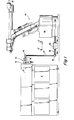
- FIGURE I is a side elevational view of a laser robotic system, employing the laser beam switching device of the present invention;
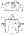
- FIGURE 2 is a plan view of the laser beam switching device taken along the line 2-2 of Figure 1;
- FIGURE 3 is a side elevational view taken along the line 3-3 of Figure 2;
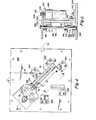
- FIGURE 4 is a plan view of the inner mechanism of Figure 2 with covers removed;
- FIGURE 5 is an elevational view of the mechanism of Figure 4, taken along the line 5-5 of Figure 4;
- FIGURE 6 is an elevational section through the pivot drive mechanism taken along the line 6-6 of Figure 4;
- FIGURE 7 is a plan section through the mirror mounting assembly taken along the line 7-7 of Figure 5; and
- FIGURE 8 is a rear elevational view of the mirror gate assembly taken along the line 8-8 of Figure 4.
- Figure I of the drawings illustrates a right side elevational view of a
laser robot 10 utilising a laser. generating unit I I mounted on a floor nearby. The laser unit I I may be any of a variety of industrial lasing units manufactured by companies such as Coherent General, Spectra-Physics, etc. The preferred laser unit I I for many power applications is a C02 gas laser, emitting alaser beam 12 along a horizontal path from theexit end 13 of the unit II. Thebeam 12 is directed into abeam combining unit 14, exiting through a light pipe 15, which is a hollow tube connected to thebeam combiner unit 14 and to a path-direction changing unit such as thecorner mirror assembly 16 shown. Themirror assembly 16 directs thebeam 12 downward along a vertical path through alight pipe 17 to asecond mirror assembly 16 which redirects thebeam 12 along a horizontal path through alight tube 18 into thebase 19 of therobot 10. Thelight pipe 18 may be continous in many applications, but for the preferred embodiment thepipe 18 may be replaced by twosections 18a, 18b with abeam switching box 20 located therebetween. - During periods of the robotic cycle when the
laser beam 12 is not needed, the beam may be routed to auxiliary units such as laser tools or robots (not shown), connected to anauxiliary light pipe 18c of the beam switching box 20 (Figure 2). - The plan view depicted in Figure 2 illustrates the square
beam switching box 20 of Figure I, having entry andexit light pipes 18a and 18b secured in position with threadedcollars 500 secured to thesides 501, 502 of thebox 20. Of the remaining twosides box 20, oneside 503 carries a multi-pinelectrical connector 505 for a motor and switches (Figures 4-8) and theother side 504 carries a threadedcollar 500 sealed with an 0-ring 506 and secured withscrews 507. Aside light pipe 18c is threadably received in thecollar 500 and held thereto by a locknut 508. Since thelight pipes 18a box 20, it can be seen from the view shown in Figure 3 that the box can be secured to abase plate 509 byscrews 510 received through thebase plate 509 and into the sides 501-504. - A
mirror 511 is pivotable between closed and open positions 511a, 511b to either reflect thelaser beam 12 to theside pipe 18c or pass thebeam 12 through to the in-line pipe 18b. - Referring simultaneously to Figures 4 and 5, the sides 501-504 of the
box 20 are removed for clarity and Figure 5 shows that thebase plate 509 carries avertical mounting plate 512 attached to a rightangle foot plate 513. The vertical mounting plate 51-2 carries a pair of identical right angle bearingblocks 514 on its opposite side, which contain bearings 515 (see Figure 6) to support avertical pivot rod 516. Thepivot rod 516, in turn, carries a mirror frame orgate 517, which is a generally square vertical plate having side- extendinglugs 518 which are bored to fit thepivot rod 516. Sawslots 519 and clampingscrews 520 secure thegate 517 to therod 516. Thegate 517 is fitted with a pair offitting washers 521 to take the vertical shake out of the assembly, thelower fitting washer 521 resting against acollar 522 secured to thepivot rod 516. The bottom of thepivot rod 516 extends into aflanged bushing 523 in thebase plate 509. The top of thepivot rod 516 carries agear 524 secured by a hub setscrew 525 tightened against a flat 526 on therod 516. The top of thevertical mounting plate 512 carries amotor mounting bracket 527 which serves to position adrive motor 528 in a vertical attitude. Theshaft 529 of thedrive motor 528 carries adrive pinion 530 secured by aset screw 531, thepinion 530 being in constant mesh with thegear 524. The plan view of Figure 4 shows that thegate 517 is pivotable between the closed position shown in solid, i.e., resting against a closedposition stop block 532, and an open position shown in phantom, i.e. resting against an openposition stop block 533. Three identicalswitch mounting brackets 534 are secured to thebase plate 509, and support identicalpush button switches switches 535a, 535b are activated or "made" when thegate 517 is in the closed position, while thethird limit switch 535c is activated by bracket 536 (secured to the back of the gate) when thegate 517 is open. As can be seen in Figure 5, the closed position of the gate and its control elements are angled with respect to the base plate to that anincoming laser beam 12 will be reflected 90° to the side when the gate is closed, and thebeam 12 will flow directly through when thegate 517 is opened. - The mirror mounting assembly for the
mirror gate 517 is shown in Figure 7, where thecircular mirror 511 is positioned in thecounterbore 537 of amirror retainer 538, theretainer 538 having a central clearance hole 599 extending therethrough. Thecounterbore 537 is threaded and received on the threaded diameter of a mirror adjustingbracket 540. Thebracket 540 has acylindrical flange 541 adjacent to the threaded diameter screwed into themirror retainer 538, and provided with astop screw 542 to prevent overtightening of the mirror .511. The back face of themirror adjusting bracket 540 has acounterbore 543 and has a circularfacial groove 544 machined into the bottom thereof, in the shape of an incomplete ring with approximately 600 between the start and stop points of the groove 544 (see Figure 8). Acover plate 545 is seated against the bottom of thecounterbore 543 to enclose thegroove 544, and a pair ofbarbed hose fittings 546 are threadably received in the coverplate to provide for coolant flow through thegroove 544 when it is desired to cool themirror 511. The outer surface 538a of themirror retainer 538 is spherical, having a radius swung from the intersection point, or reflectingpoint 547 of the surface of themirror 511 at thecentreline 548. Aspherical socket 549 is provided in asquare mounting plate 550 secured to the back of thegate 517 and accurately positioned with afitting washer 551 to establish the correct adjustment to themirror reflecting point 547. Theflange 541 of themirror adjusting bracket 540 has three equally-spaced swivel-pad adjustingscrews 552 which bear against themounting plate 550, and thereby provide an accurate swivel adjustment of thespherical mirror retainer 538. A plurality ofcommercial spring plungers 553, each having a threaded body and spring-loaded nose, are threadably received in theflange 541 to bias themirror retainer 538 in itsspherical socket 549. An 0-ring 554 may be provided on theretainer 538 to introduce a slight drag, to prevent slipping, when adjusting themirror 511. - The features disclosed in the foregoing description, or the following claims, or the accompanying drawings, expressed in their specific forms or in terms of a means for performing the disclosed function, or a method or process for attaining the disclosed result, or a class or group of substances or compositions, as appropriate, may, separately or in any combination of such features, be utilised for realising the invention in diverse forms thereof.
Claims (8)
Applications Claiming Priority (2)
| Application Number | Priority Date | Filing Date | Title |
|---|---|---|---|
| US84023986A | 1986-03-17 | 1986-03-17 | |
| US840239 | 1986-03-17 |
Publications (2)
| Publication Number | Publication Date |
|---|---|
| EP0241722A2 true EP0241722A2 (en) | 1987-10-21 |
| EP0241722A3 EP0241722A3 (en) | 1989-01-25 |
Family
ID=25281813
Family Applications (1)
| Application Number | Title | Priority Date | Filing Date |
|---|---|---|---|
| EP87103696A Withdrawn EP0241722A3 (en) | 1986-03-17 | 1987-03-13 | Laser beam switching device |
Country Status (3)
| Country | Link |
|---|---|
| EP (1) | EP0241722A3 (en) |
| JP (1) | JPS62275209A (en) |
| DE (1) | DE241722T1 (en) |
Cited By (2)
| Publication number | Priority date | Publication date | Assignee | Title |
|---|---|---|---|---|
| EP0857536A1 (en) * | 1997-02-05 | 1998-08-12 | Honda Giken Kogyo Kabushiki Kaisha | Laser beam welding apparatus |
| US7409779B2 (en) | 2005-10-19 | 2008-08-12 | Nike, Inc. | Fluid system having multiple pump chambers |
Citations (3)
| Publication number | Priority date | Publication date | Assignee | Title |
|---|---|---|---|---|
| GB897496A (en) * | 1959-05-27 | 1962-05-30 | Fernseh Gmbh | Device for selection among alternative optical paths |
| FR2523363A1 (en) * | 1982-03-12 | 1983-09-16 | Gentric Alain | Bistable electromagnetic light beam switch - has rotating arm with two rest positions one of which sets mirror in path of light beam |
| JPS6096391A (en) * | 1983-10-28 | 1985-05-29 | Shinkawa Ltd | Laser working machine |
-
1987
- 1987-03-13 DE DE1987103696 patent/DE241722T1/en active Pending
- 1987-03-13 EP EP87103696A patent/EP0241722A3/en not_active Withdrawn
- 1987-03-17 JP JP6232287A patent/JPS62275209A/en active Pending
Patent Citations (3)
| Publication number | Priority date | Publication date | Assignee | Title |
|---|---|---|---|---|
| GB897496A (en) * | 1959-05-27 | 1962-05-30 | Fernseh Gmbh | Device for selection among alternative optical paths |
| FR2523363A1 (en) * | 1982-03-12 | 1983-09-16 | Gentric Alain | Bistable electromagnetic light beam switch - has rotating arm with two rest positions one of which sets mirror in path of light beam |
| JPS6096391A (en) * | 1983-10-28 | 1985-05-29 | Shinkawa Ltd | Laser working machine |
Non-Patent Citations (1)
| Title |
|---|
| PATENT ABSTRACTS OF JAPAN, vol. 9, no. 242 (M-417)[1965], 28th September 1985; & JP-A-60 096 391 (SHINKAWA K.K.) 29-05-1985 * |
Cited By (3)
| Publication number | Priority date | Publication date | Assignee | Title |
|---|---|---|---|---|
| EP0857536A1 (en) * | 1997-02-05 | 1998-08-12 | Honda Giken Kogyo Kabushiki Kaisha | Laser beam welding apparatus |
| US6072149A (en) * | 1997-02-05 | 2000-06-06 | Honda Giken Kogyo Kabushiki Kaisha | Laser beam welding apparatus |
| US7409779B2 (en) | 2005-10-19 | 2008-08-12 | Nike, Inc. | Fluid system having multiple pump chambers |
Also Published As
| Publication number | Publication date |
|---|---|
| JPS62275209A (en) | 1987-11-30 |
| DE241722T1 (en) | 1988-02-25 |
| EP0241722A3 (en) | 1989-01-25 |
Similar Documents
| Publication | Publication Date | Title |
|---|---|---|
| US6452131B2 (en) | Apparatus and control system for laser welding | |
| US4626999A (en) | Apparatus for controlled manipulation of laser focus point | |
| US4695701A (en) | Laser wrist | |
| US4661680A (en) | End-of-arm tooling carousel apparatus for use with a robot | |
| US5685999A (en) | Compact laser machining head with integrated on-line path control for laser machining of material | |
| US5961858A (en) | Laser welding apparatus employing a tilting mechanism | |
| EP0245608A2 (en) | Laser beam combiner | |
| US4892992A (en) | Industrial laser robot system | |
| US4698479A (en) | Beam delivery system for a CO2 laser | |
| US3993402A (en) | Apparatus for directing a laser beam | |
| US4652133A (en) | Vision system with environmental control | |
| US5140129A (en) | Multi-articulated arm type industrial laser robot | |
| US4707585A (en) | Laser wrist with sealed beam pathway | |
| EP0241722A2 (en) | Laser beam switching device | |
| EP1170085B1 (en) | A focusing head for a laser machine | |
| US5484982A (en) | Beam axis adjusting method for a laser robot | |
| JPH05506517A (en) | Deflection mirror housing and beam separation filter for laser material processing equipment | |
| US5493095A (en) | Laser beam divergence compensation apparatus | |
| KR970005926B1 (en) | Laser robot system for industrial use | |
| GB2153785A (en) | Laser beam delivery system | |
| JPH0782154B2 (en) | Device for delivering parallel beams such as laser beams | |
| EP0237987B1 (en) | Laser beam diverter and robotic assembly comprising a laser beam diverter | |
| US4698482A (en) | Laser robot | |
| EP0413826A1 (en) | Method and apparatus for laser machining using non-axisymmetric parabolic reflector | |
| DE29716121U1 (en) | Robotic hand for processing workpieces with laser radiation |
Legal Events
| Date | Code | Title | Description |
|---|---|---|---|
| PUAI | Public reference made under article 153(3) epc to a published international application that has entered the european phase |
Free format text: ORIGINAL CODE: 0009012 |
|
| AK | Designated contracting states |
Kind code of ref document: A2 Designated state(s): DE FR GB IT SE |
|
| ITCL | It: translation for ep claims filed |
Representative=s name: JACOBACCI CASETTA & PERANI S.P.A. |
|
| EL | Fr: translation of claims filed | ||
| DET | De: translation of patent claims | ||
| PUAL | Search report despatched |
Free format text: ORIGINAL CODE: 0009013 |
|
| AK | Designated contracting states |
Kind code of ref document: A3 Designated state(s): DE FR GB IT SE |
|
| STAA | Information on the status of an ep patent application or granted ep patent |
Free format text: STATUS: THE APPLICATION IS DEEMED TO BE WITHDRAWN |
|
| 18D | Application deemed to be withdrawn |
Effective date: 19890726 |
|
| RIN1 | Information on inventor provided before grant (corrected) |
Inventor name: HAFFNER, JAMES L. Inventor name: ROSS, TONY LEE |