EP0241241A1 - Information display apparatus - Google Patents
Information display apparatus Download PDFInfo
- Publication number
- EP0241241A1 EP0241241A1 EP87302942A EP87302942A EP0241241A1 EP 0241241 A1 EP0241241 A1 EP 0241241A1 EP 87302942 A EP87302942 A EP 87302942A EP 87302942 A EP87302942 A EP 87302942A EP 0241241 A1 EP0241241 A1 EP 0241241A1
- Authority
- EP
- European Patent Office
- Prior art keywords
- elements
- display apparatus
- information display
- frame
- activating means
- Prior art date
- Legal status (The legal status is an assumption and is not a legal conclusion. Google has not performed a legal analysis and makes no representation as to the accuracy of the status listed.)
- Granted
Links
Images


Classifications
-
- G—PHYSICS
- G09—EDUCATION; CRYPTOGRAPHY; DISPLAY; ADVERTISING; SEALS
- G09F—DISPLAYING; ADVERTISING; SIGNS; LABELS OR NAME-PLATES; SEALS
- G09F9/00—Indicating arrangements for variable information in which the information is built-up on a support by selection or combination of individual elements
- G09F9/30—Indicating arrangements for variable information in which the information is built-up on a support by selection or combination of individual elements in which the desired character or characters are formed by combining individual elements
- G09F9/37—Indicating arrangements for variable information in which the information is built-up on a support by selection or combination of individual elements in which the desired character or characters are formed by combining individual elements being movable elements
- G09F9/375—Indicating arrangements for variable information in which the information is built-up on a support by selection or combination of individual elements in which the desired character or characters are formed by combining individual elements being movable elements the position of the elements being controlled by the application of a magnetic field
Definitions
- This invention relates to information display apparatus and more particularly to visual information display apparatus.
- Information display apparatus are known in which an image is formed by selectively displaying an appropriate face of one or more character forming elements. Electromagnetic means have been used to actuate the elements to change the image. Such display apparatus are of complex construction in that they require an electromagnet for each element.
- An aim of the present invention is to reduce the number of activating means to provide a display apparatus of simplified and compact construction.
- an information display apparatus comprising a frame in which are mounted a plurality of moveable elements having at least two display areas and an array of activating means, wherein the frame of elements and the array of activating means are moveable relative to each other such that on selective energisation of the activating means one or more of the plurality of elements is or are moved to create a changeable display of information.
- the frame of moveable elements is rotatable relative to the array of activating means.
- the frame of elements may be arranged on a cylindrical surface which is rotatable with a fixed array of activating means.
- the frame of elements can be arranged as a fixed linear surface which is traversed by the array of activating means.
- the activating means comprises an array of electromagnets which are selectively energised.
- the electromagnets control air jets which impinge on the plurality of elements to rotate one or more elements to display a changeable image.
- the activating means are preferably microprocessor controlled to display changeable characters or images.
- each frame is provided with a series of timing marks offset by a distance twice the width of the moveable elements.
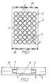
- the display apparatus comprises a frame l made up from one or more units generally indicated at 2.
- Each frame unit 2 is formed with a plurality of apertures 3 in which are rotatably mounted disc-shaped elements 4 each element having two display surfaces 5 and 6.
- These discs are made of a soft magnetic material and are each pivoted about two pins 7 located in bearings formed by recessed portions 8 in the frame.
- the frame unit is made up of a laminate of sheet metal 9, of a hard magnetic material of low magnetic remanence, e.g. mild steel, and another layer l0 of a hard magnetic material of low remanence.
- a hard magnetic material of low magnetic remanence e.g. mild steel
- another layer l0 of a hard magnetic material of low remanence e.g. mild steel
- the two pins 7 are located in bearings formed by the recessed portions 8 sandwiched in between the layers of sheet metal.
- Each disc-shaped element 4 has two contrasting surfaces which can be of a fluorescent sheet material, or coated with other suitable material such as paint.
- the discs are arranged to pivot about their pins along axes at 45 degrees to the sides of the frame units 2.
- the frames are thus divided along magnetic lines south pole - null - north pole - null - south pole etc.
- the combined magnetic effect of the laminate acts as a detent to maintain the alignment of the rotatable elements flat with the plane of the frame units.
- each frame unit 2 Arranged at the sides of each frame unit 2 are a series of timing marks 20 which are offset by a distance of twice the diameter of the disc-shaped elements 4.
- FIGS. 3 to 6 illustrate a preferred construction of the invention in which the frame and elements are arranged as a cylinder ll which is rotated by a motor (not shown) about an axis relative to a fixed activating means l2.
- the activating means comprises a vertical support which carries an array of seven electromagnets projecting into an aperture l3 formed in a fixed cylindrical wall l4 located inside cylindrical frame ll.
- One wall of the aperture l3 is rigid and is curved to provide a smooth guide l5 for each rotatable element 4 as it is attracted by an adjacent electromagnet and pivoted about its pins 7.
- the other wall of the aperture is provided with a curved flexible member l6 which eliminates the effect of extraneous stray magnetic influence and to gently urge the rotatable element attracted by the electromagnet over its 90 degree pivot point to display its other surface.
- the cylindrical frame ll of rotatable display elements is rotated in the direction of arrow 'A' about an axis such that successive rows of elements pass adjacent to the array of electromagnets of the activating means l2.
- the electromagnets are selectively energised to attract one or more rotatable elements and pivot them about their axis.
- the curved side l5 of the wall aperture guides the elements through 90 degrees until the resiliently flexible side wall l6 urges the element over its 90 degree position as it passes the activating means causing it to rotate through l80 degrees to display its other surface.
- the activating means takes the form of a vertical support l2 which carries an array of seven electromagnets l2 a which are traversed by the cylindrical wall ll made up of a plurality of frame units.
- Each frame unit is formed with circular apertures l3 in each of which is mounted a disc-shaped rotatable element 4.
- Located at one end of the electromagnets l2 a is a printed circuit board l7.
- a brush l8 Secured at each side of the electromagnets l2 a is a brush l8 which engages the partially energised disc 4 and gently brushes them through l80 degrees to their reversed position. The brushes will minimise air flow over the elements to prevent the leading brush air flow disturbing the alignment.
- FIGs 8 and 9 illustrate another embodiment of the information display apparatus comprising a fixed linear housing 2l with a reciprocating activating means 22.
- the housing 2l has an elongated rectangular cross-section with closing end plates 23.
- the front rectangular face of the display apparatus has an array of frame units 2 of the type illustrated in Figures l and 2.
- the activating means 22 reciprocates laterally along the array of fixed frame units 2.
- the activating means is illustrated on an enlarged scale in Figure 8 and comprises a support l2 ⁇ which carries a plurality of electromagnets l2 a ⁇ which can be individually energised to attract selective ones of the magnetic discs 4 ⁇ as it is traversed past them causing them to rotate through l80 degrees to show their reverse face and form an information display.
- the activating means is traversed along its linear path by a cable 24 and capstan 25 device, the capstan 25 being driven by an electric motor 26.
- a brush l8 ⁇ is mounted on each side of the electromagnets l2 a to engage the partially energised disc 4 to gently brush them through l80 degrees to their reverse position.
- the cable and capstan device may be replaced by a toothed belt engaging a motor driven toothed wheel, providing a positive reciprocating motion to the energising means.
- the array of frame units 2 form a two line display but this can be enlarged to more than two lines to provide a greater display area.
- the arrangement and shape of the rotatable elements in the frame structure provide a display which can be rapidly changed to provide a variety of characters, designs or animated images.
- the preferred embodiment describes a cylindrical display surface moveable relative to a fixed actuating means, it is equally possible to provide a fixed display surface containing the rotatable elements, and move the activating means in close proximity to the rotatable elements to rotate them by selectively energising the electromagnets of the activating means.
- One arrangement for driving the activating means causing them to traverse the display surface is to mount them on a support rod with a drive belt to pull the activating means to and fro along the display surface.
- Another method of moving the activating means along a linear path can be by means of a lead-screw which rotates and causes a nut on the lead-screw, which nut is fixed to the activating means, to move along the lead-screw to traverse the display surface selectively rotating the elements.
- the energising means has been described as electromagnetic it is, of course, possible to use other forms of activation such as blasts of air controlled by electrically activated valves, which blasts would impinge on the rotatable elements to selectively rotate them about their axes.
- the selective actuation of the electromagnetic means are preferably microprocessor controlled to provide a pre-programmed changing of the display.
- the programmed changing of the display can alternatively be under the control of a computer keyboard where characters on the display can be altered to display messages or urgent information.
- An enhancement to the invention would be the provision of sensing means to sense the current position of the rotatable elements.
- Such sensing means would preferably be mounted adjacent to the activating means and arranged such that one sensor is provided for each horizontal row of rotatable elements.
- the relative movement of the activating means and sensing means, and the array of rotatable elements, would enable the status of all rotatable elements to be ascertained by the sensing means; the information so derived could then be used by the microprocessor to decide whether a given rotatable element needs to be rotated when setting up a new image on the display surface.
Abstract
Description
- This invention relates to information display apparatus and more particularly to visual information display apparatus.
- Information display apparatus are known in which an image is formed by selectively displaying an appropriate face of one or more character forming elements. Electromagnetic means have been used to actuate the elements to change the image. Such display apparatus are of complex construction in that they require an electromagnet for each element.
- An aim of the present invention is to reduce the number of activating means to provide a display apparatus of simplified and compact construction.
- According to the present invention there is provided an information display apparatus comprising a frame in which are mounted a plurality of moveable elements having at least two display areas and an array of activating means,
wherein the frame of elements and the array of activating means are moveable relative to each other such that on selective energisation of the activating means one or more of the plurality of elements is or are moved to create a changeable display of information. - Conveniently the frame of moveable elements is rotatable relative to the array of activating means.
- The frame of elements may be arranged on a cylindrical surface which is rotatable with a fixed array of activating means. Alternatively the frame of elements can be arranged as a fixed linear surface which is traversed by the array of activating means.
- Preferably the activating means comprises an array of electromagnets which are selectively energised.
- In another construction the electromagnets control air jets which impinge on the plurality of elements to rotate one or more elements to display a changeable image.
- The activating means are preferably microprocessor controlled to display changeable characters or images.
- The sides of each frame are provided with a series of timing marks offset by a distance twice the width of the moveable elements.
- An embodiment of the invention will now be described, by way of example, with reference to the accompanying drawings, in which :
- Figure l is a front elevation of a display unit, according to the present invention ;
- Figure 2 is an enlarged cross-section taken along the line II-II of Figure l ;
- Figures 3 to 6 are diagrammatic views showing the movement of a cylindrical display relative to a fixed activating means ;
- Figure 7 is a modified diagrammatic view of the cylindrical display shown in Figures 3 to 6 and
- Figure 8 is an alternative form of display showing a fixed linear housing with a reciprocating activating means.
- Figure 9 is a perspective view with portions broken away, of the fixed linear housing of Figure 8.
- The display apparatus comprises a frame l made up from one or more units generally indicated at 2. Each
frame unit 2 is formed with a plurality of apertures 3 in which are rotatably mounted disc-shaped elements 4 each element having twodisplay surfaces pins 7 located in bearings formed by recessedportions 8 in the frame. - The frame unit is made up of a laminate of sheet metal 9, of a hard magnetic material of low magnetic remanence, e.g. mild steel, and another layer l0 of a hard magnetic material of low remanence. In the construction illustrated the two
pins 7 are located in bearings formed by the recessedportions 8 sandwiched in between the layers of sheet metal. - Each disc-
shaped element 4 has two contrasting surfaces which can be of a fluorescent sheet material, or coated with other suitable material such as paint. The discs are arranged to pivot about their pins along axes at 45 degrees to the sides of theframe units 2. The frames are thus divided along magnetic lines south pole - null - north pole - null - south pole etc. The combined magnetic effect of the laminate acts as a detent to maintain the alignment of the rotatable elements flat with the plane of the frame units. - Arranged at the sides of each
frame unit 2 are a series oftiming marks 20 which are offset by a distance of twice the diameter of the disc-shaped elements 4. - With reference now to Figures 3 to 6 these illustrate a preferred construction of the invention in which the frame and elements are arranged as a cylinder ll which is rotated by a motor (not shown) about an axis relative to a fixed activating means l2. The activating means comprises a vertical support which carries an array of seven electromagnets projecting into an aperture l3 formed in a fixed cylindrical wall l4 located inside cylindrical frame ll. One wall of the aperture l3 is rigid and is curved to provide a smooth guide l5 for each
rotatable element 4 as it is attracted by an adjacent electromagnet and pivoted about itspins 7. The other wall of the aperture is provided with a curved flexible member l6 which eliminates the effect of extraneous stray magnetic influence and to gently urge the rotatable element attracted by the electromagnet over its 90 degree pivot point to display its other surface. - In operation the cylindrical frame ll of rotatable display elements is rotated in the direction of arrow 'A' about an axis such that successive rows of elements pass adjacent to the array of electromagnets of the activating means l2. As each row of elements passes the aperture l3 in the wall into which the electromagnets project, the electromagnets are selectively energised to attract one or more rotatable elements and pivot them about their axis. The curved side l5 of the wall aperture guides the elements through 90 degrees until the resiliently flexible side wall l6 urges the element over its 90 degree position as it passes the activating means causing it to rotate through l80 degrees to display its other surface.
- In a modified construction of the cylindrical display illustrated in Figure 7 the activating means takes the form of a vertical support l2 which carries an array of seven electromagnets l2a which are traversed by the cylindrical wall ll made up of a plurality of frame units. Each frame unit is formed with circular apertures l3 in each of which is mounted a disc-shaped
rotatable element 4. Located at one end of the electromagnets l2a is a printed circuit board l7. Secured at each side of the electromagnets l2a is a brush l8 which engages the partiallyenergised disc 4 and gently brushes them through l80 degrees to their reversed position. The brushes will minimise air flow over the elements to prevent the leading brush air flow disturbing the alignment. - Figures 8 and 9 illustrate another embodiment of the information display apparatus comprising a fixed linear housing 2l with a reciprocating
activating means 22. The housing 2l has an elongated rectangular cross-section withclosing end plates 23. The front rectangular face of the display apparatus has an array offrame units 2 of the type illustrated in Figures l and 2. - Located within the housing 2l the activating means 22 reciprocates laterally along the array of
fixed frame units 2. The activating means is illustrated on an enlarged scale in Figure 8 and comprises a support l2ʹ which carries a plurality of electromagnets l2aʹ which can be individually energised to attract selective ones of the magnetic discs 4ʹ as it is traversed past them causing them to rotate through l80 degrees to show their reverse face and form an information display. The activating means is traversed along its linear path by acable 24 andcapstan 25 device, thecapstan 25 being driven by anelectric motor 26. A brush l8ʹ is mounted on each side of the electromagnets l2a to engage the partiallyenergised disc 4 to gently brush them through l80 degrees to their reverse position. - In a modified construction the cable and capstan device may be replaced by a toothed belt engaging a motor driven toothed wheel, providing a positive reciprocating motion to the energising means.
- The array of
frame units 2 form a two line display but this can be enlarged to more than two lines to provide a greater display area. - It will be appreciated that the arrangement and shape of the rotatable elements in the frame structure provide a display which can be rapidly changed to provide a variety of characters, designs or animated images.
- The simplicity of having a single array of activating means to selectively alter the display reduces the cost and improves the operating efficiency of the display apparatus.
- Although the preferred embodiment describes a cylindrical display surface moveable relative to a fixed actuating means, it is equally possible to provide a fixed display surface containing the rotatable elements, and move the activating means in close proximity to the rotatable elements to rotate them by selectively energising the electromagnets of the activating means.
- One arrangement for driving the activating means causing them to traverse the display surface is to mount them on a support rod with a drive belt to pull the activating means to and fro along the display surface. Another method of moving the activating means along a linear path can be by means of a lead-screw which rotates and causes a nut on the lead-screw, which nut is fixed to the activating means, to move along the lead-screw to traverse the display surface selectively rotating the elements.
- Although the energising means has been described as electromagnetic it is, of course, possible to use other forms of activation such as blasts of air controlled by electrically activated valves, which blasts would impinge on the rotatable elements to selectively rotate them about their axes.
- The selective actuation of the electromagnetic means are preferably microprocessor controlled to provide a pre-programmed changing of the display. The programmed changing of the display can alternatively be under the control of a computer keyboard where characters on the display can be altered to display messages or urgent information.
- An enhancement to the invention would be the provision of sensing means to sense the current position of the rotatable elements. Such sensing means would preferably be mounted adjacent to the activating means and arranged such that one sensor is provided for each horizontal row of rotatable elements. The relative movement of the activating means and sensing means, and the array of rotatable elements, would enable the status of all rotatable elements to be ascertained by the sensing means; the information so derived could then be used by the microprocessor to decide whether a given rotatable element needs to be rotated when setting up a new image on the display surface.
Claims (17)
Priority Applications (1)
| Application Number | Priority Date | Filing Date | Title |
|---|---|---|---|
| AT87302942T ATE70139T1 (en) | 1986-04-05 | 1987-04-03 | INFORMATION DISPLAY DEVICE. |
Applications Claiming Priority (2)
| Application Number | Priority Date | Filing Date | Title |
|---|---|---|---|
| GB8608363 | 1986-04-05 | ||
| GB868608363A GB8608363D0 (en) | 1986-04-05 | 1986-04-05 | Information display apparatus |
Publications (2)
| Publication Number | Publication Date |
|---|---|
| EP0241241A1 true EP0241241A1 (en) | 1987-10-14 |
| EP0241241B1 EP0241241B1 (en) | 1991-12-04 |
Family
ID=10595750
Family Applications (1)
| Application Number | Title | Priority Date | Filing Date |
|---|---|---|---|
| EP87302942A Expired - Lifetime EP0241241B1 (en) | 1986-04-05 | 1987-04-03 | Information display apparatus |
Country Status (6)
| Country | Link |
|---|---|
| US (1) | US4926167A (en) |
| EP (1) | EP0241241B1 (en) |
| AT (1) | ATE70139T1 (en) |
| AU (1) | AU7105287A (en) |
| DE (1) | DE3774922D1 (en) |
| GB (2) | GB8608363D0 (en) |
Cited By (2)
| Publication number | Priority date | Publication date | Assignee | Title |
|---|---|---|---|---|
| EP0316095A1 (en) * | 1987-11-05 | 1989-05-17 | Bright-Tech (Developments) Limited | An improved information display apparatus |
| WO1995010103A1 (en) * | 1993-10-05 | 1995-04-13 | Bright-Tech Developments Limited | Display apparatus |
Families Citing this family (1)
| Publication number | Priority date | Publication date | Assignee | Title |
|---|---|---|---|---|
| JPH0738102B2 (en) * | 1988-10-12 | 1995-04-26 | 日方 若竹 | Rotating display element and display device using the same |
Citations (4)
| Publication number | Priority date | Publication date | Assignee | Title |
|---|---|---|---|---|
| US1765215A (en) * | 1927-08-22 | 1930-06-17 | Duchard Henri Maurice | Publicity apparatus |
| US3267595A (en) * | 1963-06-05 | 1966-08-23 | Levy | Display unit |
| GB1220338A (en) * | 1966-12-12 | 1971-01-27 | Trans Lux Corp | Fluid-jet operated monogrammic travelling display systems |
| DE2244322A1 (en) * | 1972-09-09 | 1974-03-21 | Klaus J Dipl Ing Hecker | ELECTRICALLY ADJUSTABLE DISPLAY BOARD |
Family Cites Families (12)
| Publication number | Priority date | Publication date | Assignee | Title |
|---|---|---|---|---|
| GB295989A (en) * | 1927-08-22 | 1928-11-29 | Henri Maurice Duchard | Improvements in and relating to monogrammic apparatus for publicity purposes |
| GB1023667A (en) * | 1961-11-17 | 1966-03-23 | Levy Associates Company Ltd | Display unit |
| US3199098A (en) * | 1963-02-14 | 1965-08-03 | Samuel A Schwartz | Display apparatus having spheres mounted on rods |
| US3283427A (en) * | 1963-11-13 | 1966-11-08 | Ferranti Packard Ltd | Method and apparatus for construction of an electromagnetically operated sign |
| US3374565A (en) * | 1965-09-27 | 1968-03-26 | Recognition Equipment Inc | Moving display system |
| FR1582678A (en) * | 1967-09-16 | 1969-10-03 | ||
| US3486258A (en) * | 1967-12-06 | 1969-12-30 | Contraves Ag | Movable display arrangement |
| AU7448074A (en) * | 1973-10-26 | 1976-04-29 | Caritato Ltd | Programmable displays |
| SE7910071L (en) * | 1978-12-08 | 1980-06-09 | Roy Mcgreevy | Display apparatus |
| GB2101386B (en) * | 1981-06-16 | 1984-10-24 | Robin Warne | Visual display apparatus |
| JPS5898776A (en) * | 1981-12-07 | 1983-06-11 | 若竹 雅之 | Display element and display unit using same |
| US4694289A (en) * | 1982-12-08 | 1987-09-15 | E.R.G. Management Services Pty., Ltd. | Display member |
-
1986
- 1986-04-05 GB GB868608363A patent/GB8608363D0/en active Pending
-
1987
- 1987-04-02 US US07/034,126 patent/US4926167A/en not_active Expired - Fee Related
- 1987-04-03 DE DE8787302942T patent/DE3774922D1/en not_active Expired - Lifetime
- 1987-04-03 GB GB08707985A patent/GB2189067A/en not_active Withdrawn
- 1987-04-03 EP EP87302942A patent/EP0241241B1/en not_active Expired - Lifetime
- 1987-04-03 AT AT87302942T patent/ATE70139T1/en not_active IP Right Cessation
- 1987-04-03 AU AU71052/87A patent/AU7105287A/en not_active Abandoned
Patent Citations (4)
| Publication number | Priority date | Publication date | Assignee | Title |
|---|---|---|---|---|
| US1765215A (en) * | 1927-08-22 | 1930-06-17 | Duchard Henri Maurice | Publicity apparatus |
| US3267595A (en) * | 1963-06-05 | 1966-08-23 | Levy | Display unit |
| GB1220338A (en) * | 1966-12-12 | 1971-01-27 | Trans Lux Corp | Fluid-jet operated monogrammic travelling display systems |
| DE2244322A1 (en) * | 1972-09-09 | 1974-03-21 | Klaus J Dipl Ing Hecker | ELECTRICALLY ADJUSTABLE DISPLAY BOARD |
Cited By (2)
| Publication number | Priority date | Publication date | Assignee | Title |
|---|---|---|---|---|
| EP0316095A1 (en) * | 1987-11-05 | 1989-05-17 | Bright-Tech (Developments) Limited | An improved information display apparatus |
| WO1995010103A1 (en) * | 1993-10-05 | 1995-04-13 | Bright-Tech Developments Limited | Display apparatus |
Also Published As
| Publication number | Publication date |
|---|---|
| GB2189067A (en) | 1987-10-14 |
| AU7105287A (en) | 1987-10-08 |
| EP0241241B1 (en) | 1991-12-04 |
| GB8707985D0 (en) | 1987-05-07 |
| ATE70139T1 (en) | 1991-12-15 |
| GB8608363D0 (en) | 1986-05-08 |
| DE3774922D1 (en) | 1992-01-16 |
| US4926167A (en) | 1990-05-15 |
Similar Documents
| Publication | Publication Date | Title |
|---|---|---|
| US4761905A (en) | Scanned electromechanical display | |
| US3949392A (en) | Multi-element display apparatus for displaying different patterns or information | |
| US6819228B2 (en) | Scanning braille presentation | |
| EP0357251A2 (en) | High speed shuttle printer | |
| EP0241241A1 (en) | Information display apparatus | |
| JPS5931713B2 (en) | information display device | |
| US3537197A (en) | Lever operated display device | |
| EP0327250A2 (en) | Electromagnetic display device | |
| US4912442A (en) | Scanned electromechanical alphanumeric display | |
| US4115941A (en) | Display and reset apparatus | |
| US4259801A (en) | Display device | |
| EP0584837B1 (en) | A display apparatus | |
| US3589672A (en) | Solenoid controlled valve and armature with adjustable bias | |
| US3924226A (en) | Display device having an array of movable display elements | |
| GB2188470A (en) | Display element | |
| US3659366A (en) | Display apparatus | |
| EP0083844A1 (en) | Display element and display panel using the same | |
| US3624647A (en) | Translatable display sign | |
| EP0316095A1 (en) | An improved information display apparatus | |
| AU760452B2 (en) | Display device and array | |
| EP0067678A1 (en) | Visual display apparatus | |
| US3281853A (en) | Display marking apparatus | |
| EP0487696B1 (en) | Numeral display device | |
| EP1024471A1 (en) | Display element for electromagnetic displays | |
| GB1598646A (en) | Paper tape punch and reader |
Legal Events
| Date | Code | Title | Description |
|---|---|---|---|
| PUAI | Public reference made under article 153(3) epc to a published international application that has entered the european phase |
Free format text: ORIGINAL CODE: 0009012 |
|
| AK | Designated contracting states |
Kind code of ref document: A1 Designated state(s): AT BE CH DE ES FR GB IT LI NL SE |
|
| 17P | Request for examination filed |
Effective date: 19880405 |
|
| RAP1 | Party data changed (applicant data changed or rights of an application transferred) |
Owner name: BRIGHT-TECH (DEVELOPMENTS) LIMITED |
|
| 17Q | First examination report despatched |
Effective date: 19891130 |
|
| GRAA | (expected) grant |
Free format text: ORIGINAL CODE: 0009210 |
|
| AK | Designated contracting states |
Kind code of ref document: B1 Designated state(s): AT BE CH DE ES FR GB IT LI NL SE |
|
| PG25 | Lapsed in a contracting state [announced via postgrant information from national office to epo] |
Ref country code: IT Free format text: LAPSE BECAUSE OF FAILURE TO SUBMIT A TRANSLATION OF THE DESCRIPTION OR TO PAY THE FEE WITHIN THE PRE;WARNING: LAPSES OF ITALIAN PATENTS WITH EFFECTIVE DATE BEFORE 2007 MAY HAVE OCCURRED AT ANY TIME BEFORE 2007. THE CORRECT EFFECTIVE DATE MAY BE DIFFERENT FROM THE ONE RECORDED.SCRIBED TIME-LIMIT Effective date: 19911204 Ref country code: SE Effective date: 19911204 Ref country code: BE Effective date: 19911204 Ref country code: AT Effective date: 19911204 Ref country code: CH Effective date: 19911204 Ref country code: LI Effective date: 19911204 Ref country code: NL Effective date: 19911204 |
|
| REF | Corresponds to: |
Ref document number: 70139 Country of ref document: AT Date of ref document: 19911215 Kind code of ref document: T |
|
| REF | Corresponds to: |
Ref document number: 3774922 Country of ref document: DE Date of ref document: 19920116 |
|
| REG | Reference to a national code |
Ref country code: CH Ref legal event code: PL |
|
| PG25 | Lapsed in a contracting state [announced via postgrant information from national office to epo] |
Ref country code: ES Free format text: LAPSE BECAUSE OF FAILURE TO SUBMIT A TRANSLATION OF THE DESCRIPTION OR TO PAY THE FEE WITHIN THE PRESCRIBED TIME-LIMIT Effective date: 19920315 |
|
| EN | Fr: translation not filed | ||
| PG25 | Lapsed in a contracting state [announced via postgrant information from national office to epo] |
Ref country code: FR Effective date: 19920424 |
|
| NLV1 | Nl: lapsed or annulled due to failure to fulfill the requirements of art. 29p and 29m of the patents act | ||
| PLBE | No opposition filed within time limit |
Free format text: ORIGINAL CODE: 0009261 |
|
| STAA | Information on the status of an ep patent application or granted ep patent |
Free format text: STATUS: NO OPPOSITION FILED WITHIN TIME LIMIT |
|
| 26N | No opposition filed | ||
| REG | Reference to a national code |
Ref country code: FR Ref legal event code: ST |
|
| PGFP | Annual fee paid to national office [announced via postgrant information from national office to epo] |
Ref country code: GB Payment date: 19980401 Year of fee payment: 12 |
|
| PGFP | Annual fee paid to national office [announced via postgrant information from national office to epo] |
Ref country code: DE Payment date: 19980429 Year of fee payment: 12 |
|
| PG25 | Lapsed in a contracting state [announced via postgrant information from national office to epo] |
Ref country code: GB Free format text: LAPSE BECAUSE OF NON-PAYMENT OF DUE FEES Effective date: 19990403 |
|
| GBPC | Gb: european patent ceased through non-payment of renewal fee |
Effective date: 19990403 |
|
| PG25 | Lapsed in a contracting state [announced via postgrant information from national office to epo] |
Ref country code: DE Free format text: LAPSE BECAUSE OF NON-PAYMENT OF DUE FEES Effective date: 20000201 |