EP0240817A2 - Dispensing device for mixtures - Google Patents
Dispensing device for mixtures Download PDFInfo
- Publication number
- EP0240817A2 EP0240817A2 EP87104211A EP87104211A EP0240817A2 EP 0240817 A2 EP0240817 A2 EP 0240817A2 EP 87104211 A EP87104211 A EP 87104211A EP 87104211 A EP87104211 A EP 87104211A EP 0240817 A2 EP0240817 A2 EP 0240817A2
- Authority
- EP
- European Patent Office
- Prior art keywords
- chamber
- closure
- admixing
- riser pipe
- discharge
- Prior art date
- Legal status (The legal status is an assumption and is not a legal conclusion. Google has not performed a legal analysis and makes no representation as to the accuracy of the status listed.)
- Granted
Links
Images

Classifications
-
- B—PERFORMING OPERATIONS; TRANSPORTING
- B05—SPRAYING OR ATOMISING IN GENERAL; APPLYING FLUENT MATERIALS TO SURFACES, IN GENERAL
- B05B—SPRAYING APPARATUS; ATOMISING APPARATUS; NOZZLES
- B05B11/00—Single-unit hand-held apparatus in which flow of contents is produced by the muscular force of the operator at the moment of use
- B05B11/0005—Components or details
- B05B11/0078—Arrangements for separately storing several components
- B05B11/0081—Arrangements for separately storing several components and for mixing the components in a common container as a mixture ready for use before discharging the latter
-
- B—PERFORMING OPERATIONS; TRANSPORTING
- B05—SPRAYING OR ATOMISING IN GENERAL; APPLYING FLUENT MATERIALS TO SURFACES, IN GENERAL
- B05B—SPRAYING APPARATUS; ATOMISING APPARATUS; NOZZLES
- B05B11/00—Single-unit hand-held apparatus in which flow of contents is produced by the muscular force of the operator at the moment of use
- B05B11/01—Single-unit hand-held apparatus in which flow of contents is produced by the muscular force of the operator at the moment of use characterised by the means producing the flow
- B05B11/10—Pump arrangements for transferring the contents from the container to a pump chamber by a sucking effect and forcing the contents out through the dispensing nozzle
- B05B11/1042—Components or details
- B05B11/1043—Sealing or attachment arrangements between pump and container
- B05B11/1046—Sealing or attachment arrangements between pump and container the pump chamber being arranged substantially coaxially to the neck of the container
- B05B11/1047—Sealing or attachment arrangements between pump and container the pump chamber being arranged substantially coaxially to the neck of the container the pump being preassembled as an independent unit before being mounted on the container
-
- B—PERFORMING OPERATIONS; TRANSPORTING
- B05—SPRAYING OR ATOMISING IN GENERAL; APPLYING FLUENT MATERIALS TO SURFACES, IN GENERAL
- B05B—SPRAYING APPARATUS; ATOMISING APPARATUS; NOZZLES
- B05B15/00—Details of spraying plant or spraying apparatus not otherwise provided for; Accessories
- B05B15/30—Dip tubes
-
- B—PERFORMING OPERATIONS; TRANSPORTING
- B65—CONVEYING; PACKING; STORING; HANDLING THIN OR FILAMENTARY MATERIAL
- B65D—CONTAINERS FOR STORAGE OR TRANSPORT OF ARTICLES OR MATERIALS, e.g. BAGS, BARRELS, BOTTLES, BOXES, CANS, CARTONS, CRATES, DRUMS, JARS, TANKS, HOPPERS, FORWARDING CONTAINERS; ACCESSORIES, CLOSURES, OR FITTINGS THEREFOR; PACKAGING ELEMENTS; PACKAGES
- B65D81/00—Containers, packaging elements, or packages, for contents presenting particular transport or storage problems, or adapted to be used for non-packaging purposes after removal of contents
- B65D81/32—Containers, packaging elements, or packages, for contents presenting particular transport or storage problems, or adapted to be used for non-packaging purposes after removal of contents for packaging two or more different materials which must be maintained separate prior to use in admixture
- B65D81/3216—Rigid containers disposed one within the other
- B65D81/3222—Rigid containers disposed one within the other with additional means facilitating admixture
-
- B—PERFORMING OPERATIONS; TRANSPORTING
- B65—CONVEYING; PACKING; STORING; HANDLING THIN OR FILAMENTARY MATERIAL
- B65D—CONTAINERS FOR STORAGE OR TRANSPORT OF ARTICLES OR MATERIALS, e.g. BAGS, BARRELS, BOTTLES, BOXES, CANS, CARTONS, CRATES, DRUMS, JARS, TANKS, HOPPERS, FORWARDING CONTAINERS; ACCESSORIES, CLOSURES, OR FITTINGS THEREFOR; PACKAGING ELEMENTS; PACKAGES
- B65D83/00—Containers or packages with special means for dispensing contents
- B65D83/14—Containers or packages with special means for dispensing contents for delivery of liquid or semi-liquid contents by internal gaseous pressure, i.e. aerosol containers comprising propellant for a product delivered by a propellant
- B65D83/32—Dip-tubes
-
- B—PERFORMING OPERATIONS; TRANSPORTING
- B65—CONVEYING; PACKING; STORING; HANDLING THIN OR FILAMENTARY MATERIAL
- B65D—CONTAINERS FOR STORAGE OR TRANSPORT OF ARTICLES OR MATERIALS, e.g. BAGS, BARRELS, BOTTLES, BOXES, CANS, CARTONS, CRATES, DRUMS, JARS, TANKS, HOPPERS, FORWARDING CONTAINERS; ACCESSORIES, CLOSURES, OR FITTINGS THEREFOR; PACKAGING ELEMENTS; PACKAGES
- B65D83/00—Containers or packages with special means for dispensing contents
- B65D83/14—Containers or packages with special means for dispensing contents for delivery of liquid or semi-liquid contents by internal gaseous pressure, i.e. aerosol containers comprising propellant for a product delivered by a propellant
- B65D83/68—Dispensing two or more contents, e.g. sequential dispensing or simultaneous dispensing of two or more products without mixing them
- B65D83/682—Dispensing two or more contents, e.g. sequential dispensing or simultaneous dispensing of two or more products without mixing them the products being first separated, but finally mixed, e.g. in a dispensing head
- B65D83/687—Dispensing two or more contents, e.g. sequential dispensing or simultaneous dispensing of two or more products without mixing them the products being first separated, but finally mixed, e.g. in a dispensing head the products being totally mixed on, or prior to, first use, e.g. by breaking an ampoule containing one of the products
-
- Y—GENERAL TAGGING OF NEW TECHNOLOGICAL DEVELOPMENTS; GENERAL TAGGING OF CROSS-SECTIONAL TECHNOLOGIES SPANNING OVER SEVERAL SECTIONS OF THE IPC; TECHNICAL SUBJECTS COVERED BY FORMER USPC CROSS-REFERENCE ART COLLECTIONS [XRACs] AND DIGESTS
- Y10—TECHNICAL SUBJECTS COVERED BY FORMER USPC
- Y10S—TECHNICAL SUBJECTS COVERED BY FORMER USPC CROSS-REFERENCE ART COLLECTIONS [XRACs] AND DIGESTS
- Y10S215/00—Bottles and jars
- Y10S215/08—Mixing
Definitions
- the invention relates to a discharge device for mixed media comprising at least two components, with a main chamber and at least one admixing chamber closed with respect to the latter with a closure part which is accessible from the outside for opening, the component of which can be transferred into the main chamber after the closure has been opened.
- the invention has for its object to provide a discharge device of the type mentioned, in which the admixing of at least one component to at least one further component can be carried out in a simple manner so that a safe and complete transfer of the one component into the chamber the other component is guaranteed and that the mixed medium can then be discharged directly from the associated chamber for use without the main chamber having to be pressurized.
- a discharge device of the type mentioned according to the invention that at least one intermediate chamber directly adjoins the main chamber via the closure part, that the closure part can be separated from the closed position via a predetermined breaking point and that the main chamber has a holder for a suction side has to be connected to its interior manually operated discharge pump.
- the intermediate chamber and the main chamber are thus, for example, directly connected to one another via a transition opening provided in a common wall and initially kept closed with the closure part, so that after the closure part has been removed, the transition opening is essentially open over its entire width, which is precisely defined by its dimensionally stable limitation and the contents of one chamber can be transferred directly to the other chamber, avoiding any leakage losses.
- the components to be mixed can be liquids, powdery substances, gases or the like.
- each of the aforementioned forms of aggregate can also be provided for mixing with any of the two other aggregate forms.
- the admixing component can be in powder form and the main component can be liquid.
- at least one component is formed by at least one, for example detachable or catalytically active, solid body which can be brought together as a whole with the other component by the design according to the invention, since the closure completely covers the transfer path or the transfer opening releases. Due to the manually operated discharge pump connected to the main chamber in the operating state, the mixed medium can then be discharged very easily in, for example, precisely metered quantity units, so that above all those mixed media can be used which are detrimental to aerosols or similar propellants.
- a diaphragm which is to be destroyed by a riser pipe of a valve head is provided as a closure between two chambers and generally tends to lie relatively closely around the riser pipe, so that if the upper chamber were to accommodate an admixture component, a safe passage of this admixture component into the main chamber is not guaranteed would. Because the closure part in the subject matter of the invention can be separated via at least one predetermined breaking point, the disadvantages mentioned are avoided.
- the admixing chamber is inserted into the holder for the discharge pump, which is preferably designed in the manner of a neck of the vessel, so that when the main chamber is in the normal position, it is generally above its content and therefore the content of the admixing chamber Opening of the closure part under its own weight reaches the main chamber by itself.
- the walls of the admixing chamber in one piece with those of the main chamber, there is an embodiment which is particularly easy to manufacture and handle if the admixing chamber is provided in the form of a separate container inserted into the main chamber, which is preferably on the outer end face the holder for the discharge pump is sealed with a flange ring.
- closure part is provided in a bottom wall of the preferably cup-shaped admixing chamber and, in particular, it takes up almost the entire bottom wall, practically the entire associated wall is broken out to open the connection between the admixing chamber and the main chamber, so that it is ensured with particular certainty that the entire Contents of the admixing chamber reaches the main chamber.
- the construction and handling of the discharge device according to the invention can be significantly simplified in that the closure part can be opened by the discharge pump that can be inserted from the outside into a chamber, in particular the mixing chamber, so that the discharge pump first of all from the container forming the mixing and the main chamber is provided separately and for mixing the compo
- the discharge pump which can be detached as a whole only has to be attached to the container in its operating position.
- the closure part forms a solid component with a riser pipe for the discharge pump, which is only connected to the pump when the discharge pump is inserted into the container, the relatively sensitive and therefore easily damaged inner end of the riser pipe need not be used to open the closure part and it can also be avoided that the closure part is in an uncontrolled position in the main chamber after opening.
- the closure part can be formed on the one hand in one piece with the riser tube and on the other hand in one piece with the admixing comb, so that in a preferred embodiment the admixing chamber, closure member and riser tube or the like by means of a single integral component made of plastic. are formed.
- the one-piece design of the closure part with the admixing chamber and the connection of the closure part with the admixing chamber exclusively via the predetermined breaking point enables an extremely dense formation of the admixing chamber even without special effort, so that even in the worst case, no proportions of the admixing component can get into the main chamber unintentionally.
- any closure that can be opened from the outside can be provided, it being conceivable, for example, to close a closure cap for the neck of the vessel or the admixing chamber on the inside with a closure member for the riser pipe provided so that this closure member is simultaneously removed from the riser when removing the closure cap.
- a target Breakage is connected in one piece to the riser pipe and is arranged so that it can be opened by the discharge pump which can be inserted from the outside.
- the pipe closure is advantageously protected inside the riser pipe, the outer end of which is expediently designed as a plug outer sleeve for receiving an end piece of the discharge pump housing provided as an intake pipe.
- the pipe closure is broken open by itself and thus opened.
- the pipe closure can be designed so that it consists of individual segments which connect to one another via further predetermined breaking points and detach from one another when opened, these segments then each having a maximum width which is smaller than the clear width of the inner channel of the riser pipe, so that it is guaranteed with certainty that the broken pipe closure does not get stuck in the riser pipe, but falls completely into the main chamber, where it does not prevent.
- the predetermined breaking point of the pipe closure has a lower breaking strength than the predetermined breaking point of the closure part, so that the closure part is only broken free when the plug connection between the discharge pump and the riser pipe is established.
- a stop for example formed by the opposite bottom of the main chamber, for the inner end of the riser pipe, against which the inner end of the riser pipe strikes in a position which corresponds to its operating position connected to the discharge pump, so that when inserted
- the discharge part of the discharge pump can first be opened, after which the final operational connection between the discharge pump and the riser pipe is established by breaking the pipe closure.
- the inner end of the climb Pipe or the stop formed so that the inner end is not closed in the operating position, but is open, for example laterally in the jacket for sucking in the mixed medium.
- the design according to the invention is particularly suitable for discharge devices in which the discharge pump is designed as a thrust piston pump, the pump chamber of which is preferably connected to the intake port via an inlet valve, and the discharge channel of which, in particular in the piston rod, has at least one outlet valve.
- This discharge pump is suitable for both liquid and pasty media, can be adjusted to precisely metered discharge quantities and also enables atomized or sprayed discharge of the mixed medium. Furthermore, such a discharge pump has the essential advantage that, in the case of sensitive mixed media, the durability of the discharge valve and any ventilation provided for it in the main chamber are closed in the initial state.
- a discharge device 1 As shown in FIGS. 1 to 4, a discharge device 1 according to the invention has a storage or receiving container 2 for all media components to be mixed and a discharge pump 3 in the form of a hand-operated push piston pump which is held outside the container 2 before mixing and discharge of the components on, which is connected to the container 2 for mixing the components and for discharging the mixed components according to FIG. 3.
- a discharge pump 3 in the form of a hand-operated push piston pump which is held outside the container 2 before mixing and discharge of the components on, which is connected to the container 2 for mixing the components and for discharging the mixed components according to FIG. 3.
- the container 2 has, as a bottle-shaped outer container, a main chamber 4, into which an admixing chamber 5 integrated with a riser pipe 6 is inserted as an inner, substantially smaller-volume container.
- the admixing chamber 5 is substantially smaller than the main chamber 4 both in terms of its cross sections and in terms of its length or height.
- the main chamber 4 has a sleeve-shaped holder 7 on its upper end wall 9, the inside width of which is considerably smaller than the inside width the rest of the main chamber 4 and which only projects outwards beyond the end wall 9.
- This holder 7 is formed in one piece in the manner of a vessel neck with all the other walls of the main chamber 4 and also forms the filling opening for filling the main chamber 4 with the main component.
- the essentially constant internal width of the holder 7 over its length is only slightly larger than the outer circumferential width of the admixture mer 5, which has approximately constant cross sections over its entire height and engages with a small gap distance in the holder 7 such that its inner end protrudes inward beyond the end wall 9, but a large or its largest part is within the holder 7.
- the admixing chamber 5 is thus connected to the main chamber 4 in the manner of a simple plug-in connection and is centered relative to the holder 7 in its position which is axially identical to the central axis l0 of the discharge device l.
- the admixing chamber 5 has a flange ring 11 projecting over its outer circumference, which has the same outer cross section as the associated end of the holder 7 and bears against the end face 12 thereof with an intermediate ring seal 13. Adjacent to the flange ring II, the admixing chamber 5 has a section which is widened in the outside width for centering relative to the holder 7.
- the bottom wall l5 of the cup-shaped admixing chamber 5, which is open at its outer end to its full width, is formed in one piece with the jacket wall l4 of the admixing chamber 5 and with the riser pipe 6, which has constant cross sections over its entire length.
- a longitudinal section of the riser tube 6 projecting into the admixing chamber 5 is shorter than the admixing chamber 5, so that the end of this longitudinal section is provided between the wall 15 and the open end of the admixing chamber 5.
- the other longitudinal section protrudes from the bottom wall l5 into the main chamber 4, but is in the state according to FIG. 2 from its opposite bottom wall l6 a relatively large distance.
- a closure part l7 which forms at least a central part of the bottom wall l5 and projects with the part of the bottom wall or the jacket wall l4 adjoining its outer circumference, projects in a ring collar over the outer circumference of the riser tube 6 a predetermined breaking point l8 is connected in one piece.
- the predetermined breaking point 18 formed by a considerable weakening of the thickness of the wall of the admixing chamber 5 is closed by at least one ring around the central axis 10 Notch groove defined on the inside or on the outside of the associated wall of the admixing chamber 5, such notches 19, 20 being substantially congruent and of the same cross-section or the same depth being provided on both sides in the exemplary embodiment shown.
- the predetermined breaking point 18 can also have a width which is at least approximated to the inner width of the admixing chamber 5.
- the outside width of the riser pipe 6, in particular of its part projecting into the admixing chamber 5, is considerably smaller than the inside width of the admixing chamber 5, for example only about half as large.
- the closure cap 8 engages over the holder 7 on the outside and is secured in its closed position relative to the holder 7 by suitable securing members.
- the securing members 2l are formed by an external thread on the holder 7 and an internal thread on the jacket of the closure cap 8.
- they can also be formed by the members of a snap lock, a spring lock or by a separate securing member that can only be removed by destruction and serves as a seal.
- the flat end wall of the closure cap 8 lies in a sealed manner on the flange ring 11 and presses it against the holder 7, so that the main chamber 4 and the admixing chamber 5 are closed to one another by the closure cap 8 and each individual chamber is closed to the outside on the other hand.
- the admixing chamber 5 is open at its top, the admixing chamber 5 being able to be filled with the associated admixing component only over part or almost its entire height.
- the main chamber 4 remains closed to the outside, ie the admixing chamber 5 is also closed in relation to the main chamber 4 in this state.
- a pipe closure 22 which in the Riser pipe 6 is provided within the admixing chamber 5, namely relatively close to the associated end of the riser pipe 6.
- the disk-shaped or membrane-shaped pipe closure 22 is formed in one piece with the riser pipe 6 and connects to the boundary of its inner channel via an annular predetermined breaking point 23.
- the pipe closure 22 lies within a connection 25 provided for the plug-in connection with an intake port 27 of the discharge pump 3, which is formed by the associated end of the riser pipe 6 designed as a plug-in outer sleeve 26.
- the outer end section of this outer sleeve 26 has a slightly larger inner width than the remaining riser pipe 6 and the outer circumference of the intake manifold 27, this section passing over an intermediate section 28 tapering in the shape of a truncated cone into the subsequent, narrower inner channel 24 and the pipe closure 22 at the transition between the intermediate section 28 and the remaining inner channel 24.
- the length of the further end portion of the outer sleeve 26 is of the order of about half the length of the intake manifold 27, so that it can engage approximately half its length in the adjoining inner channel 24, the internal cross section of which is adapted to the external cross section of the intake manifold 27 that this engages sealed.
- the discharge pump 3 is inserted into the admixing chamber 5 in such a way that the suction nozzle 27 dips into the outer sleeve 26. After striking the end face of the intake manifold 27 on the pipe closure 22, this is broken open by further insertion of the discharge pump 3, so that the intake manifold 27 completely penetrates into the riser pipe 6 into its operating position according to FIG. 3.
- the discharge pump 3 strikes with an end stop 29 on the associated forehead Surface of the riser pipe 6, this end stop 29 being formed by a frustoconical annular shoulder 29 adjoining the intake manifold 27, which, by engaging in the inner edge of the outer sleeve 26, contributes to further sealing the connection between discharge pump 3 and riser pipe 6.
- the discharge pump 3 has not yet reached its operating position in relation to the container 2, in which it has an annular flange 30 projecting beyond the outside of its housing, which is expediently formed by an outer cylinder cover cap of the housing, with the interposition of an annular seal 3l on the outer End face of the flange ring 11 abuts and thereby closes the admixing chamber 5.
- the discharge pump 3 is pressed further into the admixing chamber 5, taking the riser pipe 6 connected to it in a clamped manner via the end stop 29, breaking the predetermined breaking point 18.
- the closure part 17 is completely released from the admixing chamber 5, so that an annular transition opening 32 from the admixing chamber 5 to the main chamber 4 is exposed around the riser pipe 6.
- the admixing component located in the admixing chamber 5 flows automatically into the main chamber 4, in which it is brought together with the main component located there and mixed if necessary by shaking. This mixing is further promoted by the admixing chamber 5 projecting into the main chamber 4 and the ring-shaped closure part 17, since these parts contribute to the swirling of the flow.
- a closure cap 8 replacing sleeve, which is expediently secured by the same securing members 2l of the holder 7 as the closure cap 8, that is, in the exemplary embodiment shown is designed as a screw sleeve 8 'with which the discharge pump 3 can be securely clamped.
- the discharge pump 3 is designed in the exemplary embodiment shown as a thrust piston pump, the cylinder housing of which projects into the admixing chamber 5 and is reduced in the outer diameter several times over the entire length of the admixing chamber 5.
- the discharge pump 3 has a piston unit 34 which can be displaced in the cylinder housing 33 and has an elastic piston sleeve 35 which is formed in one piece at its outer end with an elastically resilient compression sleeve 36.
- the piston sleeve 35 and the compression sleeve 36 are arranged on the outer circumference of a piston tappet 37 which is penetrated by a discharge channel 38 leading to its end located outside the pump housing.
- the piston sleeve 35 forms the outer, annular valve closing part of an outlet valve 39, the valve seat of which is provided on the piston tappet 37.
- the piston sleeve 35 including the valve closing part, can be moved against the direction of the pump stroke, with the compression sleeve 36 springing back against the piston tappet 37, as a result of which the outlet valve 39 opens. This movement can take place either towards the end of the pump stroke by abutment of the piston sleeve 35 on an inner shoulder of the cylinder housing 33 or, depending on the pressure, through a corresponding excess pressure in the pump chamber.
- the discharge pump 3 has an inlet valve 40 in the form of a ball valve, which closes when there is excess pressure in the pump chamber, that is to say during the pumping stroke.
Abstract
Eine Austragvorrichtung (l) weist für jede der miteinander in einer Hauptkammer (4) zu mischenden Zumischkomponenten eine Zumischkammer (5) auf, die in eine durch einen Gefäßhals gebildete Halterung (7) der Hauptkammer (4) eingesetzt ist. Eine Wandung der Zumischkammer (5) ist im wesentlichen als Verschlußteil (l7) ausgebildet, der über eine Sollbruchstelle (l8) einteilig mit der Zumischkammer (5) verbunden ist und einen Bestandteil eines Steigrohres (6) bildet. Zur Inbetriebnahme der Austragvorrichtung wird ein Verschluß geöffnet und eine Austragpumpe (3) innerhalb der Halterung (7) in die Zumischkammer (5) derart eingesetzt, daß die Austragpumpe (3) mit einem Ansaugstutzen (27) unter Öffnung eines Rohrverschlusses mit dem Steigrohr (6) verbunden und danach durch weiteres axiales Verschieben des Steigrohres (6) der Verschlußteil (l7) freigebrochen wird, so daß die Komponente aus der Zumischkammer (5) in die Hauptkammer (4) fließt. Durch Betätigung der Austragpumpe (3) läßt sich dann das Mischmedium unmittelbar über den Austragkanal (38) der Austragpumpe (3) austragen.A discharge device (1) has a mixing chamber (5) for each of the mixing components to be mixed in a main chamber (4), which is inserted into a holder (7) of the main chamber (4) formed by a neck of the vessel. One wall of the admixing chamber (5) is essentially designed as a closure part (l7), which is connected in one piece to the admixing chamber (5) via a predetermined breaking point (l8) and forms part of a riser pipe (6). To start up the discharge device, a closure is opened and a discharge pump (3) is inserted into the admixing chamber (5) within the holder (7) in such a way that the discharge pump (3) with an intake port (27) opens a pipe closure with the riser pipe (6 ) connected and then by further axial displacement of the riser pipe (6) the closure part (l7) is broken free so that the component flows from the admixing chamber (5) into the main chamber (4). By actuating the discharge pump (3), the mixed medium can then be discharged directly via the discharge channel (38) of the discharge pump (3).
Description
Die Erfindung betrifft eine Austragvorrichtung für Mischmedien aus mindestens zwei Komponenten, mit einer Hauptkammer und mindestens einer gegenüber dieser mit einem zur Öffnung von außen zugänglichen Verschlußteil geschlossenen Zumischkammer, deren Komponente nach Öffnung des Verschlusses in die Hauptkammer überführbar ist.The invention relates to a discharge device for mixed media comprising at least two components, with a main chamber and at least one admixing chamber closed with respect to the latter with a closure part which is accessible from the outside for opening, the component of which can be transferred into the main chamber after the closure has been opened.
Technische, pharmazeutische, kosmetische und ähnliche Medien bestehen häufig aus mehreren Komponenten, die aus Gründen einer Reaktionszeit oder weil sie im gemischten Zustand zu Veränderungen, beispielsweise geringerer Haltbarkeit neigen, möglichst erst kurz vor Gebrauch gemischt werden sollten. Daher werden solche Mischmedien in der Regel getrennt voneinander in gesonderten Gefäßen bereitsgestellt und vor dem Gebrauch muß die Zumisch-Komponente nach Öffnen des zugehörigen Gefäßdeckels der Hauptkomponente zugegeben sowie mit dieser durchmischt werden. Hierzu bedarf es einiger Geschicklichkeit und auch hoher Sorgfalt, wenn es darauf an kommt, daß die Komponenten in einem genauen Mengenverhältnis miteinander gemischt werden. Ist mindestens eine Komponente von der Art, daß ihr eine unmittelbare Berührung mit Luft abträglich ist, so kann die Mischung praktisch nur unter Laborbedingungen erfolgen.Technical, pharmaceutical, cosmetic and similar media often consist of several components, which should only be mixed shortly before use for reasons of a reaction time or because they tend to change in the mixed state, for example less durability. Such mixed media are therefore usually provided separately from one another in separate vessels and, before use, the admixing component must be added to the main component after opening the associated vessel lid and mixed with it. This requires some skill and also great care when it comes down to it comes that the components are mixed together in an exact quantitative ratio. If at least one component is such that direct contact with air is detrimental to it, the mixing can practically only take place under laboratory conditions.
Der Erfindung liegt die Aufgabe zugrunde, eine Austragvorrichtung der genannten Art zu schaffen, bei welcher auf einfache Weise das Zumischen mindestens einer Komponente zu mindestens einer weiteren Komponente in einfacher Weise so vorgenommen werden kann, daß ein sicheres und vollständiges Übertreten der einen Komponente in die Kammer der anderen Komponente gewährleistet ist und daß danach das Mischmedium unmittelbar aus der zugehörigen Kammer für den Gebrauch ausgetragen werden kann, ohne daß die Hauptkammer unter Druck gesetzt werden muß.The invention has for its object to provide a discharge device of the type mentioned, in which the admixing of at least one component to at least one further component can be carried out in a simple manner so that a safe and complete transfer of the one component into the chamber the other component is guaranteed and that the mixed medium can then be discharged directly from the associated chamber for use without the main chamber having to be pressurized.
Zur Lösung dieser Aufgabe ist bei einer Austragvorrichtung der eingangs genannten Art gemäß der Erfindung vorgesehen, daß mindestens eine Zwischenkammer über den Verschlußteil unmittelbar an die Hauptkammer angrenzt, daß der Verschlußteil über eine Sollbruchstelle aus der Verschlußlage abtrennbar ist und daß die Hauptkammer eine Halterung für eine saugseitig an ihren Innenraum anzuschließende handbetätigbare Austragpumpe aufweist. Die Zwischenkammer und die Hauptkammer sind also beispielsweise über eine in einer gemeinsamen Wandung vorgesehene, zunächst mit dem Verschlußteil geschlossen gehaltene Übertrittsöffnung unmittelbar miteinander leitungsverbunden, so daß nach Abtrennen des Verschlußteiles die Übertrittsöffnung im wesentlichen auf ihrer gesamten, durch ihre formstabile Begrenzung genau definierten Weite offen ist und der Inhalt der einen Kammer unter Umgehung irgendwelcher Leckverluste unmittelbar in die andere Kammer überführt werden kann. Die zu mischenden Komponenten, die zweckmäßig fließfähig sind, können Flüssigkeiten, pulverförmige Substanzen, Gase o.dgl. sein, wobei auch jede der genannten Aggregatformen zur Mischung mit einer beliebigen der beiden anderen Aggregatformen vorgesehen sein kann. Beispielsweise kann die Zumischkomponente pulverförmig und die Hauptkomponente flüssig sein. Es ist aber des weiteren auch denkbar, daß mindestens eine Komponente durch wenigstens einen, beispielsweise lösbaren oder katalytisch wirkenden Festkörper gebildet ist, der durch die erfindungsgemäße Ausbildung als Ganzes mit der anderen Komponente zusammengebracht werden kann, da der Verschluß den Übertrittsweg bzw. die Übertrittsöffnung vollständig freigibt. Durch die im Betriebszustand an die Hauptkammer angeschlossene handbetätigbare Austragpumpe läßt sich das Mischmedium dann in beispielsweise genau dosierten Mengeneinheiten sehr einfach austragen, so daß vor allem solche Mischmedien zur Anwendung kommen können, denen Aerosole oder ähnliche Treibmittel abträglich sind.To solve this problem it is provided in a discharge device of the type mentioned according to the invention that at least one intermediate chamber directly adjoins the main chamber via the closure part, that the closure part can be separated from the closed position via a predetermined breaking point and that the main chamber has a holder for a suction side has to be connected to its interior manually operated discharge pump. The intermediate chamber and the main chamber are thus, for example, directly connected to one another via a transition opening provided in a common wall and initially kept closed with the closure part, so that after the closure part has been removed, the transition opening is essentially open over its entire width, which is precisely defined by its dimensionally stable limitation and the contents of one chamber can be transferred directly to the other chamber, avoiding any leakage losses. The components to be mixed, which are expediently flowable, can be liquids, powdery substances, gases or the like. be where each of the aforementioned forms of aggregate can also be provided for mixing with any of the two other aggregate forms. For example, the admixing component can be in powder form and the main component can be liquid. However, it is also conceivable that at least one component is formed by at least one, for example detachable or catalytically active, solid body which can be brought together as a whole with the other component by the design according to the invention, since the closure completely covers the transfer path or the transfer opening releases. Due to the manually operated discharge pump connected to the main chamber in the operating state, the mixed medium can then be discharged very easily in, for example, precisely metered quantity units, so that above all those mixed media can be used which are detrimental to aerosols or similar propellants.
Durch die US-PS 32 40 403 ist zwar eine Austragvorrichtung mit zwei durch einen Zwischendeckel getrennten Kammern bekanntgeworden, bei welcher die obere Kammer das auszutragende Medium und die untere Kammer ein Treibgas enthält, das nicht als Mischkomponente, sondern lediglich zur Erzeugung eines das Medium über einen Ventilkopf nach außen fördernden Druckes vorgesehen ist. Eine Deckelplatte zwischen den beiden Kammern wird unter dem Gasdruck in Verschlußlage gehalten, weshalb diese Ausbildung nicht zum Zusammenmischen getrennt gehaltener Mischkomponenten wie beim Erfindungsgegenstand geeignet ist. Bei einer anderen, durch die US-PS 3l 34 505 bekanntgewordenen Austragvorrichtung ist als Verschluß zwischen zwei Kammern eine durch ein Steigrohr eines Ventilkopfes zu zerstörende Membran vorgesehen, die in der Regel dazu neigt, sich relativ eng um das Steigrohr zu legen, so daß, falls die obere Kammer zur Aufnahme einer Zumischkomponente vorgesehen wäre, ein sicherer Übertritt dieser Zumischkomponente in die Hauptkammer nicht gewährleistet wäre. Dadurch, daß beim Erfindungsgegenstand der Verschlußteil über mindestens eine Sollbruchstelle abtrennbar ist, werden die genannten Nachteile vermieden.From US-PS 32 40 403 a discharge device with two chambers separated by an intermediate cover has become known, in which the upper chamber contains the medium to be discharged and the lower chamber contains a propellant gas which is not used as a mixing component, but only for producing a medium a valve head to the outside promoting pressure is provided. A cover plate between the two chambers is kept in the closed position under the gas pressure, which is why this design is not suitable for mixing separately kept mixing components as in the subject of the invention. In another discharge device which has become known from US Pat. No. 3l 34 505, a diaphragm which is to be destroyed by a riser pipe of a valve head is provided as a closure between two chambers and generally tends to lie relatively closely around the riser pipe, so that if the upper chamber were to accommodate an admixture component, a safe passage of this admixture component into the main chamber is not guaranteed would. Because the closure part in the subject matter of the invention can be separated via at least one predetermined breaking point, the disadvantages mentioned are avoided.
Eine besonders vorteilhafte Weiterbildung des Erfindungsgegenstandes besteht darin, daß die Zumischkammer in die vorzugsweise nach Art eines Gefäßhalses ausgebildete Halterung für die Austragpumpe eingesetzt ist, so daß sie bei normaler Standstellung der Hauptkammer in der Regel oberhalb von deren Inhalt liegt und deshalb der Inhalt der Zumischkammer nach Öffnen des Verschlußteiles unter seiner Gewichtskraft von selbst in die Hauptkammer gelangt. Es ist zwar denkbar, die Wandungen der Zumischkammer einteilig mit denen der Hauptkammer auszubilden, jedoch ergibt sich eine besonders einfach herzustellende und zu handhabende Ausführungsform, wenn die Zumischkammer in Form eines gesonderten, in die Hauptkammer eingesetzten Behältnisses vorgesehen ist, das vorzugsweise an der äußeren Stirnfläche der Halterung für die Austragpumpe mit einem Flanschring abgedichtet anliegt.A particularly advantageous development of the subject matter of the invention is that the admixing chamber is inserted into the holder for the discharge pump, which is preferably designed in the manner of a neck of the vessel, so that when the main chamber is in the normal position, it is generally above its content and therefore the content of the admixing chamber Opening of the closure part under its own weight reaches the main chamber by itself. Although it is conceivable to form the walls of the admixing chamber in one piece with those of the main chamber, there is an embodiment which is particularly easy to manufacture and handle if the admixing chamber is provided in the form of a separate container inserted into the main chamber, which is preferably on the outer end face the holder for the discharge pump is sealed with a flange ring.
Ist der Verschlußteil in einer Bodenwand der vorzugsweise napfförmigen Zumischkammer vorgesehen und nimmt er insbesondere annähernd die gesamte Bodenwand ein, so wird zur Öffnung der Verbindung zwischen der Zumischkammer und der Hauptkammer praktisch die gesamte zugehörige Wandung herausgebrochen, so daß besonders sicher gewährleistet ist, daß der gesamte Inhalt der Zumischkammer in die Hauptkammer gelangt.If the closure part is provided in a bottom wall of the preferably cup-shaped admixing chamber and, in particular, it takes up almost the entire bottom wall, practically the entire associated wall is broken out to open the connection between the admixing chamber and the main chamber, so that it is ensured with particular certainty that the entire Contents of the admixing chamber reaches the main chamber.
Der Aufbau sowie die Handhabung der erfindungsgemäßen Austragvorrichtung können noch wesentlich dadurch vereinfacht werden, daß der Verschlußteil durch die von außen in eine Kammer, insbesondere die Zumischkammer einführbare Austragpumpe öffenbar ist, so daß also die Austragpumpe zunächst von dem die Zumisch- und die Hauptkammer bildenden Behältnis getrennt bereitgestellt wird und zur Vermischung der Kompo nenten die als Ganzes von dem Behälter lösbare Austragpumpe lediglich in ihrer Betriebslage am Behälter angebracht werden muß.The construction and handling of the discharge device according to the invention can be significantly simplified in that the closure part can be opened by the discharge pump that can be inserted from the outside into a chamber, in particular the mixing chamber, so that the discharge pump first of all from the container forming the mixing and the main chamber is provided separately and for mixing the compo The discharge pump which can be detached as a whole only has to be attached to the container in its operating position.
Bildet dabei der Verschlußteil einen festen Bauteil mit einem Steigrohr für die Austragpumpe, das erst beim Einsetzen der Austragpumpe in den Behälter an die Pumpe angeschlossen wird, so braucht nicht das verhältnismäßig empfindliche und daher leicht zu beschädigende innere Ende des Steigrohres zum Öffnen des Verschlußteiles verwendet werden und es kann auch vermieden werden, daß sich der Verschlußteil nach dem Öffnen in unkontrollierter Lage in der Hauptkammer befindet. Des weiteren kann dadurch der Verschlußteil einerseits einteilig mit dem Steigrohr und andererseits einteilig mit der Zumischkamme ausgebildet werden, so daß also bei einer bevorzugten Ausführungsform Zumischkammer, Verschlußteil und Steigrohr durch einen einzigen einstückigen Bauteil aus Kunststoff o.dgl. gebildet sind. Die einteilige Ausbildung des Verschlußteiles mit der Zumischkammer und die Verbindung des Verschlußteiles mit der Zumischkammer ausschließlich über die Sollbruchstelle ermöglicht auch ohne besonderen Aufwand eine äußerst dichte Ausbildung der Zumischkammer, so daß auch im ungünstigsten Falle keinerlei Anteile der Zumischkomponente unbeabsichtigt in die Hauptkammer gelangen können.If the closure part forms a solid component with a riser pipe for the discharge pump, which is only connected to the pump when the discharge pump is inserted into the container, the relatively sensitive and therefore easily damaged inner end of the riser pipe need not be used to open the closure part and it can also be avoided that the closure part is in an uncontrolled position in the main chamber after opening. Furthermore, the closure part can be formed on the one hand in one piece with the riser tube and on the other hand in one piece with the admixing comb, so that in a preferred embodiment the admixing chamber, closure member and riser tube or the like by means of a single integral component made of plastic. are formed. The one-piece design of the closure part with the admixing chamber and the connection of the closure part with the admixing chamber exclusively via the predetermined breaking point enables an extremely dense formation of the admixing chamber even without special effort, so that even in the worst case, no proportions of the admixing component can get into the main chamber unintentionally.
Damit das Steigrohr keine Leitungsverbindung zwischen der Zumischkammer und der Hauptkammer herstellt, kann jeder beliebige, von außen zu öffnende Verschluß vorgesehen sein, wobei es beispielsweise denkbar ist, eine Verschlußkappe für den Gefäßhals bzw. die Zumischkammer an ihrer Innenseite mit einem Verschlußglied für das Steigrohr zu versehen, so daß dieses Verschlußglied beim Entfernen der Verschlußkappe gleichzeitig vom Steigrohr abgezogen wird. Zum hermetischen Verschluß des Steigrohres ist es jedoch besonders vorteilhaft, wenn der Rohrverschluß des Steigrohres über eine Soll bruchstelle einteilig mit dem Steigrohr verbunden und so angeordnet ist, daß er durch die von außen einführbare Austragpumpe öffenbar ist.So that the riser pipe does not establish a line connection between the admixing chamber and the main chamber, any closure that can be opened from the outside can be provided, it being conceivable, for example, to close a closure cap for the neck of the vessel or the admixing chamber on the inside with a closure member for the riser pipe provided so that this closure member is simultaneously removed from the riser when removing the closure cap. For the hermetic closure of the riser pipe, however, it is particularly advantageous if the pipe closure of the riser pipe is above a target Breakage is connected in one piece to the riser pipe and is arranged so that it can be opened by the discharge pump which can be inserted from the outside.
Vorteilhaft liegt der Rohrverschluß geschützt innerhalb des Steigrohres, dessen äußeres Ende zweckmäßig als Steck-Außenhülse für die Aufnahme eines als Ansaugstutzen vorgesehenen Endstutzens des Gehäuses der Austragpumpe ausgebildet ist. Beim Einsetzen der Austragpumpe wird dadurch der Rohrverschluß von selbst freigebrochen und somit geöffnet. Der Rohrverschluß kann daßei so ausgebildet sein, daß er aus einzelnen Segmenten besteht, die über weitere Sollbruchstellen aneinander anschließen und sich beim Öffnen voneinander lösen, wobei diese Segmente dann jeweils eine maximale Weite haben, die kleiner als die lichte Weite des Innenkanales des Steigrohres ist, so daß mit Sicherheit gewährleistet ist, daß der freigebrochene Rohrverschluß nicht im Steigrohr stecken bleibt, sondern vollständig in die Hauptkammer fällt, wo er nicht hindert.The pipe closure is advantageously protected inside the riser pipe, the outer end of which is expediently designed as a plug outer sleeve for receiving an end piece of the discharge pump housing provided as an intake pipe. When the discharge pump is inserted, the pipe closure is broken open by itself and thus opened. The pipe closure can be designed so that it consists of individual segments which connect to one another via further predetermined breaking points and detach from one another when opened, these segments then each having a maximum width which is smaller than the clear width of the inner channel of the riser pipe, so that it is guaranteed with certainty that the broken pipe closure does not get stuck in the riser pipe, but falls completely into the main chamber, where it does not prevent.
Um eine sichere Verbindung der Austragpumpe mit dem Steigrohr zu gewährleisten, ist es vorteilhaft, wenn die Sollbruchstelle des Rohrverschlusses eine geringere Bruchkraft als die Sollbruchstelle des Verschlußteiles aufweist, so daß der Verschlußteil erst freigebrochen wird, wenn die Steckverbindung zwischen Austragpumpe und Steigrohr hergestellt ist. Es ist aber auch denkbar, für das innere Ende des Steigrohres einen, beispielsweise durch den gegenüberliegenden Boden der Hauptkammer gebildeten Anschlag vorzusehen, an welchem das innere Ende des Steigrohres in einer Lage anschlägt, welche ihrer mit der Austragpumpe verbundenen Betriebslage entspricht, so daß beim Einsetzen der Austragpumpe zuerst der Verschlußteil geöffnet werden kann, wonach unter Freibrechen des Rohrverschlusses die endgültige Betriebsverbindung zwischen Austragpumpe und Steigrohr hergestellt wird. In diesem Fall ist das innere Ende des Steig rohres bzw. der Anschlag so ausgebildet, daß in der Betriebslage das innere Ende nicht verschlossen, sondern, beispielsweise seitlich im Mantel zum Ansaugen des gemischten Mediums, geöffnet ist.In order to ensure a secure connection of the discharge pump with the riser pipe, it is advantageous if the predetermined breaking point of the pipe closure has a lower breaking strength than the predetermined breaking point of the closure part, so that the closure part is only broken free when the plug connection between the discharge pump and the riser pipe is established. However, it is also conceivable to provide a stop, for example formed by the opposite bottom of the main chamber, for the inner end of the riser pipe, against which the inner end of the riser pipe strikes in a position which corresponds to its operating position connected to the discharge pump, so that when inserted The discharge part of the discharge pump can first be opened, after which the final operational connection between the discharge pump and the riser pipe is established by breaking the pipe closure. In this case, the inner end of the climb Pipe or the stop formed so that the inner end is not closed in the operating position, but is open, for example laterally in the jacket for sucking in the mixed medium.
Die erfindungsgemäße Ausbildung eignet sich insbesondere für Austragvorrichtungen, bei welchen die Austragpumpe als Schubkolbenpumpe ausgebildet ist, deren Pumpenkammer vorzugsweise über ein Einlaßventil mit dem Ansaugstutzen verbunden ist und deren insbesondere im Kolbenstößel liegender Austragkanal mindestens ein Auslaßventil aufweist. Diese Austragpumpe ist sowohl für flüssige wie pastöse Medien geeignet, kann auf genau dosierte Austragmengen justiert werden und ermöglicht auch einen zerstäubten bzw. gesprühten Austrag des Mischmediums. Des weiteren hat eine solche Austragpumpe des wesentlichen Vorteil, daß dadurch, daß das Auslaßventil und eine ggf. in ihr vorgesehene Belüftung für die Hauptkammer im Ausgangszustand federnd geschlossen sind, im Falle empfindlicher Mischmedien deren Haltbarkeit wesentlich erhöht werden kann.The design according to the invention is particularly suitable for discharge devices in which the discharge pump is designed as a thrust piston pump, the pump chamber of which is preferably connected to the intake port via an inlet valve, and the discharge channel of which, in particular in the piston rod, has at least one outlet valve. This discharge pump is suitable for both liquid and pasty media, can be adjusted to precisely metered discharge quantities and also enables atomized or sprayed discharge of the mixed medium. Furthermore, such a discharge pump has the essential advantage that, in the case of sensitive mixed media, the durability of the discharge valve and any ventilation provided for it in the main chamber are closed in the initial state.
Diese und weitere Merkmale von bevorzugten Weiterbildungen der Erfindung gehen auch aus der Beschreibung und den Zeichnungen hervor, wobei die einzelnen Merkmale jeweils für sich allein oder zu mehreren in Form von Unterkombinationen bei einer Ausführungsform der Erfindung und auf anderen Gebieten verwirklicht sein können. Ein Ausführungsbeispiel der Erfindung ist in den Zeichnungen dargestellt und wird im folgenden näher erläutert. In den Zeichnungen zeigen:
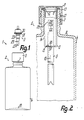
- Fig. l eine erfindungsgemäße Austragvorrichtung in Ansicht und im Lagerzustand,
- Fig. 2 einen Ausschnitt des Behälters der Austragvorrichtung gemäß Fig. l im Axialschnitt,
- Fig. 3 den Ausschnitt gemäß Fig. 2, jedoch im Betriebszustand der Austragvorrichtung,
- Fig. 4 die Zumischkammer der Austragvorrichtung gemäß den Fig. l bis 3 in wesentlich vergrößerter Darstellung und im Axialschnitt.
- 1 is a discharge device according to the invention in view and in storage condition,
- 2 shows a detail of the container of the discharge device according to FIG. 1 in axial section,
- 3 shows the detail according to FIG. 2, but in the operating state of the discharge device,
- 4 the admixing chamber of the discharge device according to FIGS. 1 to 3 in a substantially enlarged illustration and in axial section.
Wie die Fig. l bis 4 zeigen, weist eine erfindungsgemäße Austragvorrichtung l einen Speicher- bzw. Aufnahme-Behälter 2 für alle zu mischenden Medienkomponenten und eine vor der Mischung und dem Austrag der Komponenten außerhalb des Behälters 2 gehaltene Austragpumpe 3 in Form einer handbetätigbaren Schubkolbenpumpe auf, die zum Mischen der Komponenten sowie zum Austrag der gemischten Komponenten gemäß Fig. 3 mit dem Behälter 2 verbunden wird.As shown in FIGS. 1 to 4, a
Der Behälter 2 weist als flaschenförmigen Außenbehälter eine Hauptkammer 4 auf, in welche als innenliegender, wesentlich kleiner-volumiger Behälter eine mit einem Steigrohr 6 integrierte Zumischkammer 5 eingesetzt ist. Die Zumischkammer 5 ist sowohl hinsichtlich ihrer Querschnitte als auch hinsichtlich ihrer Länge bzw. Höhe wesentlich kleiner als die Hauptkammer 4. Zur Aufnahme der Zumischkammer 5 weist die Hauptkammer 4 an ihrer oberen Stirnwand 9 eine muffenförmige Halterung 7 auf, deren Innenweite wesentlich kleiner als die Innenweite der übrigen Hauptkammer 4 ist und die ausschließlich nach außen über die Stirnwand 9 vorsteht. Diese Halterung 7 ist nach Art eines Gefäßhalses einteilig mit allen übrigen Wandungen der Hauptkammer 4 ausgebildet und bildet auch die Befüllöffnung zur Befüllung der Hauptkammer 4 mit der Hauptkomponente. Die über ihre Länge im wesentlichen durchgehend konstante Innenweite der Halterung 7 ist nur geringfügig größer als die Außenumfangsweite der Zumischkam mer 5, die annähernd über ihre gesamte Höhe konstante Querschnitte aufweist und mit geringem Spaltabstand derart in die Halterung 7 eingreift, daß ihr inneres Ende nach innen über die Stirnwand 9 vorsteht, jedoch ein großer bzw. ihr größter Teil innerhalb der Halterung 7 liegt. Die Zumischkammer 5 ist somit nach Art einer einfachen Steckverbindung mit der Hauptkammer 4 verbunden und in ihrer zur Mittelachse l0 der Austragvorrichtung l achsgleichen Lage gegenüber der Halterung 7 zentriert. Am äußeren Ende weist die Zumischkammer 5 einen über ihren Außenumfang vorstehenden Flanschring ll auf, der gleichen Außenquerschnitt wie das zugehörige Ende der Halterung 7 aufweist und an deren Stirnfläche l2 unter Zwischenlage einer Ringdichtung l3 anliegt. Benachbart zum Flanschring ll weist die Zumischkammer 5 zur Zentrierung gegenüber der Halterung 7 einen in der Außenweite erweiterten Abschnitt auf. Die Boden-Wandung l5 der napfförmigen und an ihrem äußeren Ende auf voller Weite offenen Zumischkammer 5 ist einteilig mit der Mantelwandung l4 der Zumischkammer 5 sowie mit dem Steigrohr 6 ausgebildet, das annähernd über seine gesamte Länge konstante Querschnitte hat. Ein in die Zumischkammer 5 ragender Längsabschnitt des Steigrohres 6 ist kürzer als die Zumischkammer 5, so daß das Ende dieses Längsabschnittes zwischen der Wandung l5 und dem offenen Ende der Zumischkammer 5 innerhalb von dieser vorgesehen ist. Der andere Längsabschnitt ragt von der Boden-Wandung l5 in die Hauptkammer 4, hat jedoch im Zustand gemäß Fig. 2 von deren gegenüberliegender Bodenwand l6 einen verhältnismäßig großen Abstand. In der Ebene der Boden-Wandung l5 steht über den Außenumfang des Steigrohres 6 ringbundförmig ein Verschlußteil l7 vor, der wenigstens einen zentralen Teil der Boden-Wandung l5 bildet und mit dem an seinen Außenumfang anschließenden Teil der Boden-Wandung bzw. der Mantelwand l4 über eine Sollbruchstelle l8 einteilig verbunden ist. Die durch eine beträchtliche Dickenschwächung der Wandung der Zumischkammer 5 gebildete Sollbruchstelle l8 ist durch mindestens eine ringförmig um die Mittelachse l0 geschlossene Kerbnut an der Innenseite oder an der Außenseite der zugehörigen Wand der Zumischkammer 5 definiert, wobei im dargestellten Ausführungsbeispiel derartige Kerbnuten l9, 20 im wesentlichen deckungsgleich und von gleichem Querschnitt bzw. gleicher Tiefe an beiden Seiten vorgesehen sind. Die Sollbruchstelle l8 kann auch eine Weite aufweisen, die wenigstens an die Innenweite der Zumischkammer 5 angenähert ist. Die Außenweite des Steigrohres 6, insbesondere von dessen in die Zumischkammer 5 ragenden Teil, ist gegenüber der Innenweite der Zumischkammer 5 wesentlich kleiner, beispielsweise nur etwa halb so groß.The container 2 has, as a bottle-shaped outer container, a main chamber 4, into which an admixing chamber 5 integrated with a riser pipe 6 is inserted as an inner, substantially smaller-volume container. The admixing chamber 5 is substantially smaller than the main chamber 4 both in terms of its cross sections and in terms of its length or height. To accommodate the admixing chamber 5, the main chamber 4 has a sleeve-shaped holder 7 on its upper end wall 9, the inside width of which is considerably smaller than the inside width the rest of the main chamber 4 and which only projects outwards beyond the end wall 9. This holder 7 is formed in one piece in the manner of a vessel neck with all the other walls of the main chamber 4 and also forms the filling opening for filling the main chamber 4 with the main component. The essentially constant internal width of the holder 7 over its length is only slightly larger than the outer circumferential width of the admixture mer 5, which has approximately constant cross sections over its entire height and engages with a small gap distance in the holder 7 such that its inner end protrudes inward beyond the end wall 9, but a large or its largest part is within the holder 7. The admixing chamber 5 is thus connected to the main chamber 4 in the manner of a simple plug-in connection and is centered relative to the holder 7 in its position which is axially identical to the central axis l0 of the discharge device l. At the outer end, the admixing chamber 5 has a flange ring 11 projecting over its outer circumference, which has the same outer cross section as the associated end of the holder 7 and bears against the end face 12 thereof with an
Die Verschlußkappe 8 übergreift die Halterung 7 an der Außenseite und ist in ihrer Verschlußlage gegenüber der Halterung 7 durch geeignete Sicherungsglieder gesichert. Im dargestellten Ausführungsbeispiel sind die Sicherungsglieder 2l durch ein Außengewinde an der Halterung 7 und ein Innengewinde am Mantel der Verschlußkappe 8 gebildet. Sie können aber auch durch die Glieder eines Schnappverschlusses, eines Springverschlusses oder durch ein gesondertes, nur durch Zerstörung lösbares und als Versiegelung dienendes Sicherungsglied gebildet sein. Die ebene Stirnwand der Verschlußkappe 8 liegt abgedichtet am Flanschring ll an und preßt diesen gegen die Halterung 7, so daß durch die Verschlußkappe 8 einerseits die Hauptkammer 4 und die Zumischkammer 5 gegeneinander und andererseits jede einzelne Kammer für sich nach außen verschlossen ist.The
Nach Abnehmen der Verschlußkappe 8 ist die Zumischkammer 5 an ihrer Oberseite geöffnet, wobei die Zumischkammer 5 nur über einen Teil oder annähernd über ihre gesamte Höhe mit der zugehörigen Zumischkomponente gefüllt sein kann. Auch in diesem Zustand bleibt die Hauptkammer 4 nach außen verschlossen, d.h., daß auch in diesem Zustand die Zumischkammer 5 gegenüber der Hauptkammer 4 verschlossen ist. Dies wird durch einen Rohrverschluß 22 erreicht, der in dem Steigrohr 6 innerhalb der Zumischkammer 5 und zwar relativ nahe benachbart zum zugehörigen Ende des Steigrohres 6 vorgesehen ist. Der scheiben- bzw. membranförmige Rohrverschluß 22 ist einteilig mit dem Steigrohr 6 ausgebildet und schließt an die Begrenzung von dessen Innenkanal über eine ringförmige Sollbruchstelle 23 an. Diese Sollbruchstelle 23, die ebenfalls durch eine oder zwei Kertnuten gebildet sein kann, liegt so, daß nach Freibrechen des Rohrverschlusses 22 praktisch keinerlei Grat über die Begrenzungsfläche des Innenkanales 24 vorsteht. Der Rohrverschluß 22 liegt innerhalb eines für die Steckverbindung mit einem Ansaugstutzen 27 der Austragpumpe 3 vorgesehenen Anschlusses 25, der durch das als Steck-Außenhülse 26 ausgebildete zugehörige Ende des Steigrohres 6 gebildet ist. Der äußere Endabschnitt dieser Außenhülse 26 weist eine gegenüber dem übrigen Steigrohr 6 sowie gegenüber dem Außenumfang des Ansaugstutzens 27 geringfügig größere Innenweite auf, wobei dieser Abschnitt über einen spitzwinklig kegelstumpfförmig verjüngten Zwischenabschnitt 28 in den anschließenden, engeren Innenkanal 24 übergeht und der Rohrverschluß 22 am Übergang zwischen dem Zwischenabschnitt 28 und dem übrigen Innenkanal 24 liegt. Die Länge des weiteren Endabschnittes der Außenhülse 26 liegt in der Größenordnung etwa von der Hälfte der Länge des Ansaugstutzens 27, so daß dieser annähernd mit der Hälfte seiner Länge in den anschließenden Innenkanal 24 eingreifen kann, dessen Innenquerschnitt an den Außenquerschnitt des Ansaugstutzens 27 so angepaßt ist, daß dieser abgedichtet eingreift. Nach dem Abnehmen der Verschlußkappe 8 wird die Austragpumpe 3 in die Zumischkammer 5 derart eingesetzt, daß der Ansaugstutzen 27 in die Außenhülse 26 eintaucht. Nach Anschlagen der Endfläche des Ansaugstutzens 27 an dem Rohrverschluß 22 wird dieser durch weiteres Einführen der Austragpumpe 3 freigebrochen, so daß der Ansaugstutzen 27 vollends in seine Betriebslage gemäß Fig. 3 in das Steigrohr 6 eindringt. Bei Erreichen dieser Lage schlägt die Austragpumpe 3 mit einem Endanschlag 29 an der zugehörigen Stirn fläche des Steigrohres 6 an, wobei dieser Endanschlag 29 durch eine an den Ansaugstutzen 27 anschließende kegelstumpfförmige Ringschulter 29 gebildet ist, die durch Eingreifen in den Innenrand der Außenhülse 26 zur weiteren Abdichtung der Verbindung zwischen Austragpumpe 3 und Steigrohr 6 beiträgt. In dieser Lage hat die Austragpumpe 3 noch nicht ihre Betriebsstellung gegenüber dem Behälter 2 erreicht, in welcher sie mit einem über die Außenseite ihres Gehäuses vorstehenden Ringflansch 30, der zweckmäßig durch eine äußere Zylinderdeckelkappe des Gehäuses gebildet ist, unter Zwischenlage einer Ringdichtung 3l an der äußeren Stirnfläche des Flanschringes ll anliegt und dadurch die Zumischkammer 5 verschließt. Zur vollständigen Überführung in die Betriebslage wird die Austragpumpe 3 weiter in die Zumischkammer 5 hineingedrückt, wobei sie über den Endanschlag 29 das klemmend mit ihr verbundene Steigrohr 6 unter Brechen der Sollbruchstelle l8 mitnimmt. Dadurch wird der Verschlußteil l7 vollständig von der Zumischkammer 5 gelöst, so daß um das Steigrohr 6 eine ringförmige Übertrittsöffnung 32 von der Zumischkammer 5 zur Hauptkammer 4 freigelegt wird. Die in der Zumischkammer 5 befindliche Zumischkomponente fließt selbsttätig in die Hauptkammer 4, in welcher sie mit der dort befindlichen Hauptkomponente zusammengebracht und ggf. durch Schütteln vermischt wird. Diese Durchmischung wird noch durch die in die Hauptkammer 4 ragende Zumischkammer 5 und den ringtellerförmigen Verschlußteil l7 gefördert, da diese Teile zur Strömungsverwirbelung beitragen.After the
Zur Sicherung der Austragpumpe 3 dient eine die Verschlußkappe 8 ersetzende Muffe, die zweckmäßig durch dieselben Sicherungsglieder 2l der Halterung 7 wie die Verschlußkappe 8 gesichert, also im dargestellten Ausführungsbeispiel als Schraubmuffe 8ʹ ausgebildet ist, mit welcher die Austragpumpe 3 sicher festgespannt werden kann. Es ist aber auch denkbar, die am Ringflansch 30 angreifende, die Halterung 7 am Außenumfang umgebende Muffe durch andere Sicherungsglieder als die Verschlußkappe 8 gegenüber der Halterung 7 zu sichern, beispielsweise dadurch, daß sie nach Art eines Schnappverschlusses aufgesprengt ist.To secure the
Die Austragpumpe 3 ist im dargestellter Ausführungsbeispiel als Schubkolbenpumpe ausgebildet, deren in die Zumischkammer 5 ragendes, zum Ansaugstutzen 27 im Außendurchmesser mehrfach abgesetzt reduziertes Zylindergehäuse über seine gesamte Länge mit Abstand vom Innenumfang der Zumischkammer 5 liegt. Die Austragpumpe 3 weist eine im Zylindergehäuse 33 verschiebbare Kolbeneinheit 34 mit einer elastischen Kolbenmanschette 35 auf, die an ihren äußerer Ende einteilig mit einer elastisch federnden Stauchhülse 36 ausgebildet ist. Die Kolbenmanschette 35 und die Stauchhülse 36 sind am Außenumfang eines Kolbenstößels 37 angeordnet, welcher von einem zu seinem außerhalb des Pumpengehäuses liegenden Ende führenden Austragkanal 38 durchsetzt ist. Die Kolbenmanschette 35 bildet im Übergangsbereich zur Stauchhülse 36 den äußeren, ringförmigen Ventilschließteil eines Auslaßventiles 39, dessen Ventilsitz am Kolbenstößel 37 vorgesehen ist. Die Kolbenmanschette 35 kann einschließlich des Ventilschließteiles unter rückfedernder Stauchung der Stauchhülse 36 gegenüber dem Kolbenstößel 37 entgegen der Richtung des Pumphubes bewegt werden, wodurch das Auslaßventil 39 öffnet. Diese Bewegung kann entweder gegen Ende des Pumphubes durch Anschlag der Kolbenmanschette 35 an einer Innenschulter des Zylindergehäuses 33 zwangsläufig oder durckabhängig durch einen entsprechenden Überdruck in der Pumpenkammer erfolgen. Zwischen der Pumpenkammer und dem Ansaugstutzen 27 weist die Austragpumpe 3 ein Einlaßventil 40 in Form eines Kugelventiles auf, welches bei Überdruck in der Pumpenkammer, also während des Pumphubes, schließt.The
Claims (10)
Applications Claiming Priority (2)
| Application Number | Priority Date | Filing Date | Title |
|---|---|---|---|
| DE3611690 | 1986-04-08 | ||
| DE19863611690 DE3611690A1 (en) | 1986-04-08 | 1986-04-08 | DISCHARGE DEVICE FOR MIXED MEDIA |
Publications (3)
| Publication Number | Publication Date |
|---|---|
| EP0240817A2 true EP0240817A2 (en) | 1987-10-14 |
| EP0240817A3 EP0240817A3 (en) | 1988-06-29 |
| EP0240817B1 EP0240817B1 (en) | 1991-09-11 |
Family
ID=6298167
Family Applications (1)
| Application Number | Title | Priority Date | Filing Date |
|---|---|---|---|
| EP87104211A Expired - Lifetime EP0240817B1 (en) | 1986-04-08 | 1987-03-21 | Dispensing device for mixtures |
Country Status (3)
| Country | Link |
|---|---|
| US (1) | US4821923A (en) |
| EP (1) | EP0240817B1 (en) |
| DE (2) | DE3611690A1 (en) |
Cited By (5)
| Publication number | Priority date | Publication date | Assignee | Title |
|---|---|---|---|---|
| EP0606672A1 (en) * | 1992-12-09 | 1994-07-20 | Bernardino Parise | Container for substances concentrated in the form of powder or a liquid to be placed in solution within a receptacle at the time of use |
| FR2704530A1 (en) * | 1993-04-26 | 1994-11-04 | Reboul Smt | Valve for aerosol package with an additional upstream gas intake |
| EP2092985A1 (en) | 2008-02-25 | 2009-08-26 | Seriplast | Container with dip tube |
| WO2022089994A1 (en) * | 2020-10-28 | 2022-05-05 | Unilever Ip Holdings B.V. | Dispensing container and process of manufacturing a container |
| WO2022089956A1 (en) * | 2020-10-28 | 2022-05-05 | Unilever Ip Holdings B.V. | Dispensing container and process of manufacturing a container |
Families Citing this family (126)
| Publication number | Priority date | Publication date | Assignee | Title |
|---|---|---|---|---|
| ES2013413A6 (en) * | 1989-03-29 | 1990-05-01 | Monturas Sa | A dispensing pump for a fluid contained in a container. |
| IT1232115B (en) * | 1989-06-23 | 1992-01-23 | Veglia Borletti Srl | FUEL LEVEL DETECTOR DEVICE IN A VEHICLE TANK |
| US5009342A (en) * | 1989-08-14 | 1991-04-23 | Mark R. Miller | Dual liquid spraying assembly |
| US5273189A (en) * | 1991-02-14 | 1993-12-28 | Societe Technique De Pulverisation - Step | Device for spraying or dispensing a fluid, the device including a member sliding in its admission duct |
| US5252064A (en) * | 1991-02-19 | 1993-10-12 | Teledyne Industries, Inc. | Subgingival irrigator |
| US5246142A (en) * | 1991-09-26 | 1993-09-21 | Dipalma Elio | Device for storing two products separately and subsequently mixing them |
| US5620113A (en) * | 1992-05-22 | 1997-04-15 | Meshberg; Philip | Dispenser and method of its use |
| US5310089A (en) * | 1993-03-22 | 1994-05-10 | Hudgins Richard G | Liquid dispensing system |
| DE4342680A1 (en) * | 1993-12-15 | 1995-06-22 | Pfeiffer Erich Gmbh & Co Kg | Discharge device for media |
| US5590815A (en) * | 1995-07-13 | 1997-01-07 | Monturas S.A. | Minature pump sprayer |
| GB9525414D0 (en) * | 1995-12-13 | 1996-02-14 | Rocep Lusol Holdings | A device for releasing a fluid into a liquid in a container |
| US5657910A (en) * | 1996-03-25 | 1997-08-19 | Keyser; Robert O. | Safety seal for spray dispensing container |
| DE19615422A1 (en) * | 1996-04-19 | 1997-11-20 | Boehringer Ingelheim Kg | Two-chamber cartridge for propellant-free MDIs |
| DE19742559C2 (en) * | 1997-09-26 | 1999-08-05 | Gaplast Gmbh | Container with a pump |
| US6003566A (en) * | 1998-02-26 | 1999-12-21 | Becton Dickinson And Company | Vial transferset and method |
| DE19847968A1 (en) | 1998-10-17 | 2000-04-20 | Boehringer Ingelheim Pharma | Separate storage of an active material and a solvent comprises a closure cap and a container, with a chamber attached to the unit. |
| DE19933330A1 (en) * | 1999-07-16 | 2001-01-18 | Pfeiffer Erich Gmbh & Co Kg | Media Donor |
| FR2800360B1 (en) | 1999-10-29 | 2002-01-18 | Valois Sa | EXTEMPORANE MIXTURE DISPENSER |
| WO2002020172A1 (en) | 2000-09-08 | 2002-03-14 | Fresh Products, Inc. | Combination air freshener and hand lotion dispenser |
| US6598762B2 (en) * | 2001-01-31 | 2003-07-29 | Affinity Management Solutions, Inc. | Coating touch up kit |
| US6742677B2 (en) * | 2002-04-18 | 2004-06-01 | Valois S.A.S. | Fluid dispenser pump |
| US7147468B2 (en) * | 2002-12-31 | 2006-12-12 | Water Pik, Inc. | Hand held oral irrigator |
| US20040245144A1 (en) * | 2003-06-03 | 2004-12-09 | Hurst William E. | Preformed mixing bag for dry powder, apparatus, method and system for using same |
| US20040245124A1 (en) * | 2003-06-03 | 2004-12-09 | Hurst William E. | Preformed mixing bag for dry powder, apparatus, method and system for using same |
| US20050133544A1 (en) * | 2003-12-23 | 2005-06-23 | Tadlock Charles C. | Functional dip tube for cosmetic dispensers |
| US7331486B2 (en) * | 2004-04-06 | 2008-02-19 | Colgate-Palmolive Company | Pump dispenser and cartridge |
| ES2378668T3 (en) * | 2004-08-11 | 2012-04-16 | Tekni-Plex Europe Nv | Dispenser pump or bottle and tube and valve unit used in it |
| US7581662B2 (en) * | 2004-12-21 | 2009-09-01 | Michael Powell | Multi-compartment spray dispenser with common pressurizer |
| US20070203439A1 (en) | 2006-02-24 | 2007-08-30 | Water Pik, Inc. | Water jet unit and handle |
| US7670141B2 (en) | 2006-07-07 | 2010-03-02 | Water Pik, Inc. | Oral irrigator |
| US20080169316A1 (en) * | 2007-01-12 | 2008-07-17 | Ganiere Jeffrey R | Tube with pressurized spring-like action and vacuum lock regulator for rendering optimum liquid extraction and uninterrupted on-command vertical and horizontal operation and a method for retrofitting a liquid dispensing device with such tube |
| USD802120S1 (en) | 2007-02-27 | 2017-11-07 | Water Pik, Inc. | Tip for oral irrigator |
| EP2077132A1 (en) | 2008-01-02 | 2009-07-08 | Boehringer Ingelheim Pharma GmbH & Co. KG | Dispensing device, storage device and method for dispensing a formulation |
| US8302816B2 (en) * | 2008-10-15 | 2012-11-06 | Sim Jae K | Spray bottle with refill cartridge |
| US8261943B2 (en) * | 2008-10-15 | 2012-09-11 | Sim Jae K | Spray bottle with refill cartridge |
| US20100190132A1 (en) | 2009-01-28 | 2010-07-29 | Water Pik, Inc. | Oral irrigator tip |
| US10258442B2 (en) | 2009-03-20 | 2019-04-16 | Water Pik, Inc. | Oral irrigator appliance with radiant energy delivery for bactericidal effect |
| JP5670421B2 (en) | 2009-03-31 | 2015-02-18 | ベーリンガー インゲルハイム インターナショナル ゲゼルシャフト ミット ベシュレンクテル ハフツング | Component surface coating method |
| US9265910B2 (en) | 2009-05-18 | 2016-02-23 | Boehringer Ingelheim International Gmbh | Adapter, inhalation device, and nebulizer |
| US10016568B2 (en) | 2009-11-25 | 2018-07-10 | Boehringer Ingelheim International Gmbh | Nebulizer |
| WO2011064163A1 (en) | 2009-11-25 | 2011-06-03 | Boehringer Ingelheim International Gmbh | Nebulizer |
| CN102686260B (en) | 2009-11-25 | 2014-10-01 | 贝林格尔.英格海姆国际有限公司 | Nebulizer |
| USD629884S1 (en) | 2009-12-16 | 2010-12-28 | Water Pik, Inc. | Powered irrigator for sinus cavity rinse |
| US9061096B2 (en) | 2009-12-16 | 2015-06-23 | Water Pik, Inc. | Powered irrigator for sinus cavity rinse |
| EP2585151B1 (en) | 2010-06-24 | 2018-04-04 | Boehringer Ingelheim International GmbH | Nebulizer |
| USD670373S1 (en) | 2010-12-16 | 2012-11-06 | Water Pik, Inc. | Powered irrigator for sinus cavity rinse |
| WO2012130757A1 (en) | 2011-04-01 | 2012-10-04 | Boehringer Ingelheim International Gmbh | Medical device comprising a container |
| US9827384B2 (en) | 2011-05-23 | 2017-11-28 | Boehringer Ingelheim International Gmbh | Nebulizer |
| US9463560B2 (en) * | 2011-10-03 | 2016-10-11 | Illinois Tool Works Inc. | Portable pressurized power source for fastener driving tool |
| WO2013152894A1 (en) | 2012-04-13 | 2013-10-17 | Boehringer Ingelheim International Gmbh | Atomiser with coding means |
| USD707350S1 (en) | 2012-10-11 | 2014-06-17 | Water Pik, Inc. | Handheld water flosser |
| WO2014059362A2 (en) | 2012-10-11 | 2014-04-17 | Water Pik, Inc. | Interdental cleaner using water supply |
| USD717427S1 (en) | 2013-03-14 | 2014-11-11 | Water Pik, Inc. | Handle for water flosser |
| USD725770S1 (en) | 2013-03-14 | 2015-03-31 | Water Pik, Inc. | Reservoir for water flosser |
| US9642677B2 (en) | 2013-03-14 | 2017-05-09 | Water Pik, Inc. | Oral irrigator with massage mode |
| USD788907S1 (en) | 2013-03-14 | 2017-06-06 | Water Pik, Inc. | Water flosser base unit with reservoir lid |
| USD714929S1 (en) | 2013-03-14 | 2014-10-07 | Water Pik, Inc. | Base for water flosser |
| DE202013006898U1 (en) * | 2013-07-31 | 2013-08-20 | Optipharma Gmbh | drug bottle |
| EP3030298B1 (en) | 2013-08-09 | 2017-10-11 | Boehringer Ingelheim International GmbH | Nebulizer |
| EP2835146B1 (en) | 2013-08-09 | 2020-09-30 | Boehringer Ingelheim International GmbH | Nebulizer |
| ES2718685T3 (en) | 2013-11-27 | 2019-07-03 | Water Pik Inc | Oral irrigator with slide pause switch |
| US9980793B2 (en) | 2013-11-27 | 2018-05-29 | Water Pik, Inc. | Oral hygiene system |
| US10226782B2 (en) * | 2013-11-29 | 2019-03-12 | Daizo Corporation | Content-accommodating container, content-accommodating product using same, discharge product, and discharge device |
| CN203693808U (en) | 2013-12-12 | 2014-07-09 | 洁碧有限公司 | Dental water sprayer |
| US10085729B2 (en) | 2014-03-06 | 2018-10-02 | Ethicon, Inc. | Methods and devices for forming biomedical coatings using variable mixing ratios of multi-part compositions |
| EP3139982B1 (en) | 2014-05-07 | 2022-02-16 | Boehringer Ingelheim International GmbH | Nebulizer |
| KR102443737B1 (en) | 2014-05-07 | 2022-09-19 | 베링거 인겔하임 인터내셔날 게엠베하 | Container, nebulizer and use |
| DK3139984T3 (en) | 2014-05-07 | 2021-07-19 | Boehringer Ingelheim Int | Atomizer |
| EP2957347B1 (en) | 2014-06-18 | 2017-02-22 | Albea Thomaston Inc. | System for dispensing a mixture of a first product and a second product |
| USD772397S1 (en) | 2014-12-01 | 2016-11-22 | Water Pik, Inc. | Oral irrigator with a charging device |
| USD772396S1 (en) | 2014-12-01 | 2016-11-22 | Water Pik, Inc. | Handheld oral irrigator |
| CN205586102U (en) | 2014-12-01 | 2016-09-21 | 洁碧有限公司 | Waterproof wireless oral cavity flusher |
| WO2016175449A1 (en) * | 2015-04-30 | 2016-11-03 | 주식회사 삼화플라스틱 | Liquid container sealing device |
| USD780908S1 (en) | 2015-11-03 | 2017-03-07 | Water Pik, Inc. | Handheld oral irrigator |
| USD822196S1 (en) | 2016-01-14 | 2018-07-03 | Water Pik, Inc. | Oral irrigator |
| USD804018S1 (en) | 2016-07-19 | 2017-11-28 | Water Pik, Inc. | Base for an oral irrigator |
| USD802747S1 (en) | 2016-07-19 | 2017-11-14 | Water Pik, Inc. | Reservoir for oral irrigator |
| KR102072661B1 (en) | 2016-01-25 | 2020-02-03 | 워터 피크 인코포레이티드 | Mouthwashes with Reduced Shape Factors |
| USD783809S1 (en) | 2016-01-25 | 2017-04-11 | Water Pik, Inc. | Oral irrigator handle |
| USD794773S1 (en) | 2016-07-19 | 2017-08-15 | Water Pik, Inc. | Oral irrigator |
| USD819956S1 (en) | 2016-01-25 | 2018-06-12 | Water Pik, Inc. | Kit bag |
| USD796028S1 (en) | 2016-07-19 | 2017-08-29 | Water Pik, Inc. | Oral irrigator |
| USD786422S1 (en) | 2016-01-25 | 2017-05-09 | Water Pik, Inc. | Oral irrigator |
| USD782656S1 (en) | 2016-01-25 | 2017-03-28 | Water Pik, Inc. | Oral irrigator |
| US10835356B2 (en) | 2016-01-25 | 2020-11-17 | Water Pik, Inc. | Swivel assembly for oral irrigator handle |
| USD804016S1 (en) | 2016-02-05 | 2017-11-28 | Water Pik, Inc. | Handheld oral irrigator |
| USD783810S1 (en) | 2016-02-22 | 2017-04-11 | Water Pik, Inc. | Handle for an oral irrigator |
| USD809650S1 (en) | 2016-02-22 | 2018-02-06 | Water Pik, Inc. | Oral irrigator |
| USD782657S1 (en) | 2016-03-02 | 2017-03-28 | Water Pik, Inc. | Oral irrigator handle |
| KR102397188B1 (en) | 2016-03-02 | 2022-05-12 | 워터 피크 인코포레이티드 | Actuating Assembly for Mouthwash |
| USD802119S1 (en) | 2016-03-02 | 2017-11-07 | Water Pik, Inc. | Oral irrigator |
| USD807822S1 (en) | 2016-07-19 | 2018-01-16 | Water Pik, Inc. | Power supply cartridge |
| USD809651S1 (en) | 2016-07-19 | 2018-02-06 | Water Pik, Inc. | Combination base and reservoir for an oral irrigator |
| USD832419S1 (en) | 2016-12-15 | 2018-10-30 | Water Pik, Inc. | Oral irrigator unit |
| USD832420S1 (en) | 2016-12-15 | 2018-10-30 | Water Pik, Inc. | Oral irrigator base |
| USD833000S1 (en) | 2016-12-15 | 2018-11-06 | Water Pik, Inc. | Oral irrigator unit |
| USD822826S1 (en) | 2016-12-15 | 2018-07-10 | Water Pik, Inc. | Oral irrigator base |
| USD867579S1 (en) | 2016-12-15 | 2019-11-19 | Water Pik, Inc. | Oral irrigator unit |
| USD840022S1 (en) | 2016-12-15 | 2019-02-05 | Water Pik, Inc. | Oral irrigator handle |
| USD829886S1 (en) | 2016-12-15 | 2018-10-02 | Water Pik, Inc. | Oral irrigator base |
| USD839409S1 (en) | 2016-12-15 | 2019-01-29 | Water Pik, Inc. | Oral irrigator unit |
| CN114642510A (en) | 2016-12-15 | 2022-06-21 | 洁碧有限公司 | Pause valve and swivel assembly for oral irrigator handle |
| USD840023S1 (en) | 2016-12-15 | 2019-02-05 | Water Pik, Inc. | Oral irrigator reservoir |
| USD834180S1 (en) | 2016-12-15 | 2018-11-20 | Water Pik, Inc. | Oral irrigator base |
| USD825741S1 (en) | 2016-12-15 | 2018-08-14 | Water Pik, Inc. | Oral irrigator handle |
| WO2018112387A1 (en) | 2016-12-15 | 2018-06-21 | Water Pik, Inc. | Oral irrigator with magnetic attachment |
| USD833600S1 (en) | 2016-12-15 | 2018-11-13 | Water Pik, Inc. | Oral irrigator reservoir |
| USD832418S1 (en) | 2016-12-15 | 2018-10-30 | Water Pik, Inc. | Oral irrigator base |
| USD822825S1 (en) | 2016-12-15 | 2018-07-10 | Water Pik, Inc. | Oral irrigator unit |
| USD833602S1 (en) | 2017-02-06 | 2018-11-13 | Water Pik, Inc. | Oral irrigator base |
| USD833601S1 (en) | 2017-02-06 | 2018-11-13 | Water Pik, Inc. | Oral irrigator |
| USD829887S1 (en) | 2017-02-06 | 2018-10-02 | Water Pik, Inc. | Oral irrigator reservoir |
| EP4089032B1 (en) * | 2017-11-24 | 2024-04-17 | Société des Produits Nestlé S.A. | Attachment for a beverage container |
| USD868243S1 (en) | 2018-03-16 | 2019-11-26 | Water Pik, Inc. | Oral irrigator tip |
| USD877324S1 (en) | 2018-05-17 | 2020-03-03 | Water Pik, Inc. | Oral irrigator handle |
| USD912794S1 (en) | 2018-08-01 | 2021-03-09 | Fresh Products, Inc. | Air freshener |
| USD900291S1 (en) | 2018-08-06 | 2020-10-27 | Fresh Products, Inc. | Air freshener |
| USD889636S1 (en) | 2019-02-22 | 2020-07-07 | Water Pik, Inc. | Water flosser |
| USD888936S1 (en) | 2019-02-22 | 2020-06-30 | Water Pik, Inc. | Cordless water flosser |
| CN114007756B (en) * | 2019-06-14 | 2023-08-22 | 株式会社大造 | discharge device |
| DE102019129821B4 (en) * | 2019-11-05 | 2022-01-05 | Langmatz Gmbh | Sealing cap |
| US11161675B2 (en) | 2020-02-14 | 2021-11-02 | Callington Haven Pty Ltd. | Solution mixing and dispensing container system having a cartridge release mechanism |
| US11097297B1 (en) * | 2020-05-25 | 2021-08-24 | Silgan Dispensing Systems Thomaston Corporation | Large tube cover for plunger tube |
| USD966498S1 (en) | 2020-09-15 | 2022-10-11 | Water Pik, Inc. | Oral irrigator |
| USD1016274S1 (en) | 2021-02-16 | 2024-02-27 | Water Pik, Inc. | Oral irrigator |
| US11772111B1 (en) | 2022-09-16 | 2023-10-03 | Branded AcquiCo No 5, LLC | Dispenser |
Citations (7)
| Publication number | Priority date | Publication date | Assignee | Title |
|---|---|---|---|---|
| US3134505A (en) * | 1960-04-28 | 1964-05-26 | Modern Lab Inc | Pressurized dispensing device |
| US3240403A (en) * | 1960-04-28 | 1966-03-15 | Modern Lab Inc | Pressurized dispensing device |
| GB1258845A (en) * | 1969-07-31 | 1971-12-30 | Wolf Geraete Gmbh | |
| US3655096A (en) * | 1969-10-22 | 1972-04-11 | Pillsbury Co | Container for diluting and dispensing material |
| AT301439B (en) * | 1966-03-03 | 1972-09-11 | Schwarzkopf Fa Hans | Device for mixing and spraying a coloring mixture suitable for human hair |
| DE2441406A1 (en) * | 1973-08-31 | 1975-03-06 | Guala Angelo Sas | DEVICE FOR CLOSING BOTTLES ETC. |
| US4088246A (en) * | 1975-04-25 | 1978-05-09 | Colgate-Palmolive Company | Capsule and container therefor |
Family Cites Families (8)
| Publication number | Priority date | Publication date | Assignee | Title |
|---|---|---|---|---|
| US2829801A (en) * | 1955-06-22 | 1958-04-08 | Oil Equipment Lab Inc | Rupturable closure for pressurized containers |
| DE1486405A1 (en) * | 1965-04-15 | 1969-06-04 | H V Hardman Company Inc | Device for mixing and dispensing materials |
| US3355238A (en) * | 1966-08-31 | 1967-11-28 | Schwartzman Gilbert | Mixing assembly for brush-headed applicator |
| US3441177A (en) * | 1967-01-30 | 1969-04-29 | Scovill Manufacturing Co | One-shot valve assembly for aerosol container |
| US3648899A (en) * | 1969-09-11 | 1972-03-14 | Heinz Lukesch | Method and apparatus for dyeing hair |
| US4201316A (en) * | 1975-04-25 | 1980-05-06 | Colgate-Palmolive Company | Capsule having frangible wall portion |
| US4019512A (en) * | 1975-12-04 | 1977-04-26 | Tenczar Francis J | Adhesively activated sterile connector |
| US4676775A (en) * | 1984-06-27 | 1987-06-30 | David M. Roxe | Fluid administration apparatus and method |
-
1986
- 1986-04-08 DE DE19863611690 patent/DE3611690A1/en not_active Withdrawn
-
1987
- 1987-03-21 DE DE8787104211T patent/DE3772807D1/en not_active Expired - Lifetime
- 1987-03-21 EP EP87104211A patent/EP0240817B1/en not_active Expired - Lifetime
- 1987-10-07 US US07/105,884 patent/US4821923A/en not_active Expired - Lifetime
Patent Citations (7)
| Publication number | Priority date | Publication date | Assignee | Title |
|---|---|---|---|---|
| US3134505A (en) * | 1960-04-28 | 1964-05-26 | Modern Lab Inc | Pressurized dispensing device |
| US3240403A (en) * | 1960-04-28 | 1966-03-15 | Modern Lab Inc | Pressurized dispensing device |
| AT301439B (en) * | 1966-03-03 | 1972-09-11 | Schwarzkopf Fa Hans | Device for mixing and spraying a coloring mixture suitable for human hair |
| GB1258845A (en) * | 1969-07-31 | 1971-12-30 | Wolf Geraete Gmbh | |
| US3655096A (en) * | 1969-10-22 | 1972-04-11 | Pillsbury Co | Container for diluting and dispensing material |
| DE2441406A1 (en) * | 1973-08-31 | 1975-03-06 | Guala Angelo Sas | DEVICE FOR CLOSING BOTTLES ETC. |
| US4088246A (en) * | 1975-04-25 | 1978-05-09 | Colgate-Palmolive Company | Capsule and container therefor |
Cited By (6)
| Publication number | Priority date | Publication date | Assignee | Title |
|---|---|---|---|---|
| EP0606672A1 (en) * | 1992-12-09 | 1994-07-20 | Bernardino Parise | Container for substances concentrated in the form of powder or a liquid to be placed in solution within a receptacle at the time of use |
| FR2704530A1 (en) * | 1993-04-26 | 1994-11-04 | Reboul Smt | Valve for aerosol package with an additional upstream gas intake |
| EP2092985A1 (en) | 2008-02-25 | 2009-08-26 | Seriplast | Container with dip tube |
| FR2927888A1 (en) * | 2008-02-25 | 2009-08-28 | Seriplast Soc Par Actions Simp | Bottle comprising a dip tube |
| WO2022089994A1 (en) * | 2020-10-28 | 2022-05-05 | Unilever Ip Holdings B.V. | Dispensing container and process of manufacturing a container |
| WO2022089956A1 (en) * | 2020-10-28 | 2022-05-05 | Unilever Ip Holdings B.V. | Dispensing container and process of manufacturing a container |
Also Published As
| Publication number | Publication date |
|---|---|
| DE3772807D1 (en) | 1991-10-17 |
| US4821923A (en) | 1989-04-18 |
| EP0240817B1 (en) | 1991-09-11 |
| EP0240817A3 (en) | 1988-06-29 |
| DE3611690A1 (en) | 1987-10-15 |
Similar Documents
| Publication | Publication Date | Title |
|---|---|---|
| EP0240817B1 (en) | Dispensing device for mixtures | |
| EP0922499B1 (en) | Fluid dispenser | |
| EP0243667B1 (en) | Dispensing device for matter | |
| EP1027165B1 (en) | Application method for at least two different media and dispenser therefor | |
| DE3631341C2 (en) | Atomizers for flowable media | |
| EP0775530B1 (en) | Dispenser comprising two dispensing units | |
| EP0473965B1 (en) | Dispensing device for substances | |
| DE3425478C2 (en) | ||
| EP0193054B1 (en) | Dispensing device for flowable matter | |
| EP0810164B1 (en) | Apparatus for preparation of a mixture of an active substance and a diluent, as well as a method of filling a cartridge for such an apparatus | |
| DE2223471C3 (en) | Valve for use in a container, in particular in an aerosol container | |
| DE4412041A1 (en) | Discharge device for flowable media, in particular for discharge in just one stroke | |
| EP1108439B1 (en) | Product dispenser | |
| DE19756442A1 (en) | Media Donor | |
| EP0753354A2 (en) | Dispensing device for fluids, especially for dispensing in a single stroke | |
| WO2012022685A1 (en) | Dispensing module and method for filling a dispensing module | |
| DE1132508B (en) | Tubular valve stem with spray head for atomizer valves | |
| EP0761314B1 (en) | Dispensing device for fluids | |
| EP0504748A1 (en) | Dispensing device for fluids | |
| EP0516635B1 (en) | Dispenser for media | |
| EP0356679B1 (en) | One-way injection syringe | |
| EP0829307B1 (en) | Dispenser for fluids | |
| DE10258140B4 (en) | System for filling application containers | |
| DE3545409C2 (en) | Discharge device for flowable media | |
| DE19723134A1 (en) | Discharge device for media |
Legal Events
| Date | Code | Title | Description |
|---|---|---|---|
| PUAI | Public reference made under article 153(3) epc to a published international application that has entered the european phase |
Free format text: ORIGINAL CODE: 0009012 |
|
| AK | Designated contracting states |
Kind code of ref document: A2 Designated state(s): CH DE FR GB IT LI |
|
| PUAL | Search report despatched |
Free format text: ORIGINAL CODE: 0009013 |
|
| RHK1 | Main classification (correction) |
Ipc: B65D 47/34 |
|
| AK | Designated contracting states |
Kind code of ref document: A3 Designated state(s): CH DE FR GB IT LI |
|
| 17P | Request for examination filed |
Effective date: 19880913 |
|
| 17Q | First examination report despatched |
Effective date: 19900502 |
|
| RAP1 | Party data changed (applicant data changed or rights of an application transferred) |
Owner name: ING. ERICH PFEIFFER GMBH & CO. KG |
|
| GRAA | (expected) grant |
Free format text: ORIGINAL CODE: 0009210 |
|
| AK | Designated contracting states |
Kind code of ref document: B1 Designated state(s): CH DE FR GB IT LI |
|
| REF | Corresponds to: |
Ref document number: 3772807 Country of ref document: DE Date of ref document: 19911017 |
|
| GBT | Gb: translation of ep patent filed (gb section 77(6)(a)/1977) | ||
| ITF | It: translation for a ep patent filed |
Owner name: MODIANO & ASSOCIATI S.R.L. |
|
| ET | Fr: translation filed | ||
| PLBE | No opposition filed within time limit |
Free format text: ORIGINAL CODE: 0009261 |
|
| STAA | Information on the status of an ep patent application or granted ep patent |
Free format text: STATUS: NO OPPOSITION FILED WITHIN TIME LIMIT |
|
| 26N | No opposition filed | ||
| REG | Reference to a national code |
Ref country code: GB Ref legal event code: IF02 |
|
| PGFP | Annual fee paid to national office [announced via postgrant information from national office to epo] |
Ref country code: GB Payment date: 20020225 Year of fee payment: 16 |
|
| PGFP | Annual fee paid to national office [announced via postgrant information from national office to epo] |
Ref country code: FR Payment date: 20020318 Year of fee payment: 16 |
|
| PGFP | Annual fee paid to national office [announced via postgrant information from national office to epo] |
Ref country code: CH Payment date: 20020325 Year of fee payment: 16 |
|
| PGFP | Annual fee paid to national office [announced via postgrant information from national office to epo] |
Ref country code: DE Payment date: 20020522 Year of fee payment: 16 |
|
| PG25 | Lapsed in a contracting state [announced via postgrant information from national office to epo] |
Ref country code: GB Free format text: LAPSE BECAUSE OF NON-PAYMENT OF DUE FEES Effective date: 20030321 |
|
| PG25 | Lapsed in a contracting state [announced via postgrant information from national office to epo] |
Ref country code: LI Free format text: LAPSE BECAUSE OF NON-PAYMENT OF DUE FEES Effective date: 20030331 Ref country code: CH Free format text: LAPSE BECAUSE OF NON-PAYMENT OF DUE FEES Effective date: 20030331 |
|
| PG25 | Lapsed in a contracting state [announced via postgrant information from national office to epo] |
Ref country code: DE Free format text: LAPSE BECAUSE OF NON-PAYMENT OF DUE FEES Effective date: 20031001 |
|
| GBPC | Gb: european patent ceased through non-payment of renewal fee |
Effective date: 20030321 |
|
| REG | Reference to a national code |
Ref country code: CH Ref legal event code: PL |
|
| PG25 | Lapsed in a contracting state [announced via postgrant information from national office to epo] |
Ref country code: FR Free format text: LAPSE BECAUSE OF NON-PAYMENT OF DUE FEES Effective date: 20031127 |
|
| REG | Reference to a national code |
Ref country code: FR Ref legal event code: ST |
|
| PG25 | Lapsed in a contracting state [announced via postgrant information from national office to epo] |
Ref country code: IT Free format text: LAPSE BECAUSE OF NON-PAYMENT OF DUE FEES;WARNING: LAPSES OF ITALIAN PATENTS WITH EFFECTIVE DATE BEFORE 2007 MAY HAVE OCCURRED AT ANY TIME BEFORE 2007. THE CORRECT EFFECTIVE DATE MAY BE DIFFERENT FROM THE ONE RECORDED. Effective date: 20050321 |