EP0240124B1 - Lightwave communication system - Google Patents
Lightwave communication system Download PDFInfo
- Publication number
- EP0240124B1 EP0240124B1 EP87301415A EP87301415A EP0240124B1 EP 0240124 B1 EP0240124 B1 EP 0240124B1 EP 87301415 A EP87301415 A EP 87301415A EP 87301415 A EP87301415 A EP 87301415A EP 0240124 B1 EP0240124 B1 EP 0240124B1
- Authority
- EP
- European Patent Office
- Prior art keywords
- signal
- lightwave
- transceiver
- spectrum
- transceivers
- Prior art date
- Legal status (The legal status is an assumption and is not a legal conclusion. Google has not performed a legal analysis and makes no representation as to the accuracy of the status listed.)
- Expired - Lifetime
Links
- 238000004891 communication Methods 0.000 title claims description 34
- 238000001228 spectrum Methods 0.000 claims description 46
- 230000003287 optical effect Effects 0.000 claims description 38
- 238000000034 method Methods 0.000 claims description 26
- 230000007480 spreading Effects 0.000 claims description 11
- 230000008878 coupling Effects 0.000 claims description 4
- 238000010168 coupling process Methods 0.000 claims description 4
- 238000005859 coupling reaction Methods 0.000 claims description 4
- 238000001514 detection method Methods 0.000 claims description 4
- 239000000969 carrier Substances 0.000 claims 1
- 230000005540 biological transmission Effects 0.000 description 8
- 239000000835 fiber Substances 0.000 description 7
- 230000001360 synchronised effect Effects 0.000 description 5
- 239000013307 optical fiber Substances 0.000 description 4
- 230000006870 function Effects 0.000 description 3
- 230000008569 process Effects 0.000 description 3
- 230000001902 propagating effect Effects 0.000 description 3
- 230000011664 signaling Effects 0.000 description 3
- 238000010586 diagram Methods 0.000 description 2
- 239000004065 semiconductor Substances 0.000 description 2
- 238000000926 separation method Methods 0.000 description 2
- 238000010408 sweeping Methods 0.000 description 2
- 230000007704 transition Effects 0.000 description 2
- 230000009471 action Effects 0.000 description 1
- 230000003213 activating effect Effects 0.000 description 1
- 230000002411 adverse Effects 0.000 description 1
- 230000032683 aging Effects 0.000 description 1
- 230000002238 attenuated effect Effects 0.000 description 1
- 230000000903 blocking effect Effects 0.000 description 1
- 230000001427 coherent effect Effects 0.000 description 1
- 238000013461 design Methods 0.000 description 1
- 238000011161 development Methods 0.000 description 1
- 230000018109 developmental process Effects 0.000 description 1
- 230000000694 effects Effects 0.000 description 1
- 230000005672 electromagnetic field Effects 0.000 description 1
- 238000012986 modification Methods 0.000 description 1
- 230000004048 modification Effects 0.000 description 1
- 230000010355 oscillation Effects 0.000 description 1
- 238000012545 processing Methods 0.000 description 1
- 238000011160 research Methods 0.000 description 1
- 239000007787 solid Substances 0.000 description 1
Images


Classifications
-
- H—ELECTRICITY
- H04—ELECTRIC COMMUNICATION TECHNIQUE
- H04J—MULTIPLEX COMMUNICATION
- H04J14/00—Optical multiplex systems
- H04J14/02—Wavelength-division multiplex systems
- H04J14/0227—Operation, administration, maintenance or provisioning [OAMP] of WDM networks, e.g. media access, routing or wavelength allocation
-
- H—ELECTRICITY
- H04—ELECTRIC COMMUNICATION TECHNIQUE
- H04B—TRANSMISSION
- H04B1/00—Details of transmission systems, not covered by a single one of groups H04B3/00 - H04B13/00; Details of transmission systems not characterised by the medium used for transmission
- H04B1/69—Spread spectrum techniques
- H04B1/707—Spread spectrum techniques using direct sequence modulation
-
- H—ELECTRICITY
- H04—ELECTRIC COMMUNICATION TECHNIQUE
- H04J—MULTIPLEX COMMUNICATION
- H04J14/00—Optical multiplex systems
- H04J14/005—Optical Code Multiplex
-
- H—ELECTRICITY
- H04—ELECTRIC COMMUNICATION TECHNIQUE
- H04J—MULTIPLEX COMMUNICATION
- H04J14/00—Optical multiplex systems
- H04J14/02—Wavelength-division multiplex systems
- H04J14/0227—Operation, administration, maintenance or provisioning [OAMP] of WDM networks, e.g. media access, routing or wavelength allocation
- H04J14/0241—Wavelength allocation for communications one-to-one, e.g. unicasting wavelengths
-
- H—ELECTRICITY
- H04—ELECTRIC COMMUNICATION TECHNIQUE
- H04B—TRANSMISSION
- H04B2201/00—Indexing scheme relating to details of transmission systems not covered by a single group of H04B3/00 - H04B13/00
- H04B2201/69—Orthogonal indexing scheme relating to spread spectrum techniques in general
- H04B2201/707—Orthogonal indexing scheme relating to spread spectrum techniques in general relating to direct sequence modulation
- H04B2201/70715—Orthogonal indexing scheme relating to spread spectrum techniques in general relating to direct sequence modulation with application-specific features
-
- H—ELECTRICITY
- H04—ELECTRIC COMMUNICATION TECHNIQUE
- H04J—MULTIPLEX COMMUNICATION
- H04J14/00—Optical multiplex systems
- H04J14/02—Wavelength-division multiplex systems
- H04J14/0278—WDM optical network architectures
- H04J14/028—WDM bus architectures
-
- H—ELECTRICITY
- H04—ELECTRIC COMMUNICATION TECHNIQUE
- H04J—MULTIPLEX COMMUNICATION
- H04J14/00—Optical multiplex systems
- H04J14/02—Wavelength-division multiplex systems
- H04J14/0278—WDM optical network architectures
- H04J14/0283—WDM ring architectures
Definitions
- the present invention relates to lightwave communication systems and more particularly to spread spectrum multiple-access lightwave communication systems.
- optical fibers in communications systems is increasing from year to year.
- the multiple access, link length variation, etc. nature of such optical fiber systems places certain requirements on signaling and detection schemes to insure that a satisfactory predetermined error rate is achieved under varied conditions at the receivers.
- signaling and detection schemes To achieve satisfactory separation in multiple concurrent transmissions on a fiber optic system, various modulation or multiplexing techniques have been employed which are at times similar to techniques found in microwave systems.
- Spread spectrum modulation techniques have been used in terrestrial and satellite microwave communication systems to achieve security and satisfactory interference rejection at the receivers.
- spread spectrum modulation techniques have been suggested for use in optical communication systems.
- WDM Wavelength-Division-Multiplexing
- WDM Wavelength-Division-Multiplexing
- FDM Frequency-Division-Multiplexing
- DE-A-3 325 569 describes a digital telecommunications system in which individual stations in the system are connected to one another by way of a physical transmission link, such as coaxial cable or optical waveguides. Messages transmitted between stations are conveyed by means of multi-access spectrum or code spreading. A message to be transmitted is modulated in the transmitting station onto a pseudorandom bit stream, by means of a code that is assigned to the target station. In the receiving stations, it is determined by means of a code correlation whether the receiving station is the target station, and if so, the message is evaluated.
- the problem remaining in the prior art is to provide an optical communication system which uses the bandwidth of an optical waveguide arrangement , such as a single-mode optical fiber, in a substantially more efficient manner.
- the foregoing problem in the prior art is solved in accordance with the present invention which relates to a technique for transmitting a spread spectrum, code-division-multiple-access , (SS-CDMA) in a lightwave communication system and a transmitter and receiver designed to operate in such a system. More particularly, a lightwave communication technique and system, and an associated transmitter and receiver design, is disclosed wherein spread spectrum and CDMA techniques are used in addition to random Wavelength-Division-Multiplexing (WDM) in, for example, a single-mode optical waveguide arrangement, such that the transmission bandwidths of the various users, and their associated transceivers, do not necessarily coincide but are randomly scattered over the enormous channel bandwidth of the lightwave transmission medium of the system to reduce interference and efficiently use the lightguide spectrum.
- WDM Wavelength-Division-Multiplexing
- a lightwave communication system uses spread spectrum code-division-multiple-access (SS-CDMA) techniques along with wavelength-division-multiplexing (WDM), otherwise known as Frequency-Division-Multiplexing (FDM), to achieve a lightwave communication system which efficiently uses the available optical spectrum of the associated lightguide while providing adequate rejection of interference caused by one signal drifting into the bandwidth being used by another transmitter/receiver pair.
- WDM wavelength-division-multiplexing
- FDM Frequency-Division-Multiplexing
- the present invention can be used to implement, for example, a local area network capable of supporting thousands of simultaneous two-way communication channels at a relatively low data rate, e.g., 10 Mbit/sec each, with no blocking, no hierarchy, and no centralized control.
- the present network architecture can, therefore, also be used to realize a switching system capable of establishing thousands, or even tens of thousands, of high-data-rate (e.g., 10 Mbit/sec) interconnections.
- FIG. 1 is a block diagram of a preferred embodiment of the present optical communication system including an exemplary transceiver arrangement in accordance with the present invention, showing all possible elements even though certain elements can be combined or are optional.
- a plurality of N optical transceivers 101 to 10 N are coupled to an optical waveguide arrangement 11, to permit communications between pairs of the transceivers 10 i , or between a transceiver and an external network via an optional network interface unit 12 where such inter-network communication is desired.
- Optical waveguide arrangement 11 can be any optical device that combines the light signals from all the transmitters 13 of transceivers 101 to 10 N , and network interface 12 if present, and distributes the resulting superposition of signals among all receivers 14 of the N transceivers, and network interface 12, if present.
- the optical waveguide arrangement 11 might consist of a large star coupler, with an input fiber from each transmitter 13, and network interface 12 if present, and an output fiber to each receiver 14, and network interface 12 if present.
- Alternative implementations might be as an optical bus or loop or any arrangement of optical devices that achieves the same function.
- Each transceiver 10 i comprises a transmitter 13, for transmitting a signal from an associated system user over optical waveguide arrangement 11, and a receiver 14 which receives all WDM, SS-CDMA, signals propagating on optical waveguide arrangement 11 and de-spreads the desired WDM, SS-CDMA signal for delivery to the associated system user.
- FIG. 1 An exemplary transmitter 13 in each of transceivers 10 i is shown in FIG. 1 as comprising a laser source 20 which has its signal modulated by a light modulating means 21 internally or externally to source 20.
- Laser source 20 can be implemented by, for example, a semiconductor laser or any other suitable light source which is a coherent system that acts like an oscillator for generating a random carrier frequency.
- the lightwave signal of laser source 20 is modulated by modulating means 21 using any one of a variety of methods well-known in the art, including direct modulation of the laser current or external amplitude or phase modulation of the light.
- the modulating signal is either a digital or an analog signal from the associated system user.
- the modulated output signal from the directly or externally modulated laser source 20 is, therefore, an up-converted signal in a frequency band determined by laser source 20 which is shown in FIG. 1 as being delivered to a spectrum spreading device 22 which for purposes hereinafter will be considered as a Pseudo-Noise (PN) scrambling means 22.
- PN Pseudo-Noise
- PN scrambling means 22 a predetermined high-frequency pseudo-random noise code, generated by a PN sequence generator 23 under the control of a controller 24, further modulates the modulated information wave from the laser source 20/light modulator 21 combination to produce an output signal that is spread over a greater bandwidth than the information wave from modulated laser source 20, using any well known spreading technique.
- the output signal from PN scrambling means 22 is coupled into optical waveguide arrangement 11 via any well-known optical coupling device. It is to be understood that the sequence of laser source 20, light modulating means 21 and PN scrambling means 22, as shown in FIG. 1, could be modified such that the light signal from the laser source could have its spectrum spread before modulating the resulting spread spectrum carrier signal with the user signal.
- PN scrambling means 22 and PN sequence generator 23 are but one spectrum spreading technique that could be used in practicing the present invention.
- PN scrambling means 22 and PN sequence generator 23 could be replaced by a Frequency-Hopping (FH) Code Generator 26 which is used to modulate the light beam of laser source 20 and produce an output light beam wherein the output carrier frequency is hopped in a predetermined sequence.
- FH Frequency-Hopping
- the Frequency-Hopping technique as a spectrum spreading function, is well known in the art.
- a (possibly attenuated) replica of the SS-CDMA output signal from a transmitter 13 appears at each output 30 of optical waveguide arrangement 11 along with the SS-CDMA signals from all the other transmitters.
- An exemplary frequency spectrum of multiple WDM, SS-CDMA, signals, present at each output 30 of optical waveguide arrangement 11 at any point in time, is shown in FIG. 2.
- the signals propagating through optical waveguide arrangement 11 are received by each of receivers 14 of transceivers 101 to 10 N .
- the signal from optical waveguide arrangement 11 is received in a PN descrambling means 31 where the received WDM, SS-CDMA, signal, as shown in FIG. 2, is de-spread using a PN code sequence which is synchronized and matched to the PN code sequence used by a predetermined transmitter 13 of another one of transceivers 101 to 10 N forming the two-way communication.
- the PN code sequence used by PN descrambling means 31 for de-spreading the received signal is obtained from PN sequence generator 32 which is under the control of controller 33.
- the de-spread signal at the output of PN descrambling means 31 can comprise the exemplary configuration shown in FIG. 3, where the desired signal appears as a narrowband signal 39 and the other received transmissions form a smooth low-level background across the spectrum and appear as noise. It must be understood that the desired signal will only appear as a narrowband signal 39 if the PN code sequences used by the associated transmitter and receiver are the same and synchronized in their application to the spreading and de-spreading operation.
- the output signal from PN descrambling means 31 is delivered to a narrowband receiver 34 which maintains itself locked to the narrowband signal of FIG. 3 by any suitable technique as, for example, Automatic Frequency Control (AFC), and demodulates the acquired signal to a corresponding analog or digital signal for transmission to the destined user via lead 35.
- AFC Automatic Frequency Control
- narrowband receiver 34 can be realized in a variety of ways, such as through the heterodyne or homodyne, detection or through external optical filters.
- an optional network interface 12 is connected to optical waveguide arrangement 11 via appropriate coupling means at points 25 and 30 for the coupling of a WDM, SS-CDMA, signal onto optical waveguide arrangement 11 and the reception of WDM, SS-CDMA, signals from the waveguide arrangement , respectively.
- network interface 12 functions to convert signals between the external network format to that for transmission on optical waveguide arrangement 11 in any suitable manner.
- network interface 12 will not be included in the system description, but it is to be understood that if such interface were present, it would act in a manner similar to that described for any one of transceivers 101 to 10 N for providing an appropriate 2-way communication link with the external network.
- either the PN sequence generator 23 or the PM sequence generator 32 in each transceiver 10 must be "tunable" (i.e., programmable) to permit matching of its PN code sequence to that generated by the other PN sequence generator at the other end of the communication link.
- either the laser source 20 of each transceiver 10 or the narrowband receiver 34 of each transceiver 10 must tunable over the full frequency range of interest, in order to allow full network interconnectivity, i.e., any receiver can receive the signal from any transmitter.
- a preferred arrangement would be to have each narrowband receiver 34 at each of the transceivers selectively tunable to any frequency within a certain predetermined frequency range, while the laser source 20 of each transceiver 10 i is not tunable and generates an arbitrary or undetermined frequency which is not constrained in any way. Indeed, the oscillation frequency of laser source 20 might even drift erratically and fall on top of the frequency generated by the laser source 20 of another transceiver without any adverse effects on the communication links.
- the range of tunability of each narrowband receiver 34 must be large enough to include all the frequencies of oil laser sources 20 present in the system.
- frequency refers to the underlying optical carrier and is of the order of 230,000 GHz for a wavelength of 1.3 ⁇ m.
- the usage of frequency as a parameter instead of wavelength is motivated by the particular type of signal processing that makes frequency, and not wavelength, the important parameter.
- the PN Sequence Generator 23 at the associated transmitter 13 be programmable to match a PN code sequence generated by the PN Sequence Generator 32 of a desired receiver 14 in another transceiver 10, but that the PN Sequence Generator 32 at the receiver 14 would have to then be capable of synchronization to the PN Sequence Generator 23 at transmitter 13 of the link.
- Controllers 24 and 33 can be used to achieve the proper tunability and synchronization in the associated PN Sequence Generators 23 and 32 and narrowband receiver 34 as will be explained hereinafter.
- a first and a second transceiver are attempting to gain access to each other for establishing a 2-way link between the associated users of the system while others are already communicating via optical waveguide arrangement 11 as described above for the steady state condition.
- one technique would be to have user "A", associated with, for example transceiver 101 notify its controller 24, via a signaling message, that user "A” wishes to establish a link with user "B” associated with, for example, transceiver 10 N .
- Controller 24 can comprise, for example, a simple microcomputer or other device which begins by disabling the PN sequence generator 23.
- the acquisition signal that user "A" transmits over optical waveguide arrangement 11 is not spectrally spread but, rather, it looks like the narrowband acquisition signals 40 and 41 shown in FIG. 2. This signal does not interfere with already established communication links which are using spread spectrum and, thereby, are immune to narrowband interference.
- Laser source 20 at transceiver 101 is modulated by an introductory message from user "A", which introductory message can comprise certain preamble information including the address of the calling transceiver (101) and the address of the called transceiver (10 N) .
- the modulated narrowband introductory signal is sent over optical waveguide arrangement 11 as a narrowband acquisition information signal centered on the carrier frequency generated by laser source 20 of transceiver 101.
- This narrowband acquisition information signal from transmitter 13 of transceiver 101 appears as, for example, the narrowband signal 40 in FIG. 2 when looking at the overall frequency spectrum of optical waveguide arrangement 11.
- Such narrowband acquisition signal is only transmitted by the calling transceiver during acquisition, which, generally, takes a small amount of time when compared to the time the communication link is maintained after acquisition has been completed.
- Each of the receivers 14 of transceivers 101 to 10 N receives the narrowband introductory message 40 from transceiver 101 along with all other 2-way communications propagating on optical waveguide arrangement 11 from the already established communication links. If the called transceiver 10 N is not already busy on another communication link, then under the control of its controller 33 of receiver 14, its narrowband receiver 34 is caused to continuously scan the frequency spectrum in order to detect a narrowband acquisition information signal similar to signal 40 of FIG. 2 somewhere in the spectrum of optical waveguide arrangement 11. When an exemplary signal 40 is received, controller 33 detects, via its feedback path 36, that such narrowband signal exists and causes narrowband receiver 34 to lock onto the carrier frequency of the narrowband signal to permit decoding the message contained therein.
- this transceiver will unlock its narrowband receiver 34 and resume scanning the spectrum, repeating the above process until it obtains an acquisition information message indicating that this is the transceiver being called.
- controller 33 of the called transceiver 10 N After locking onto an acquisition information signal and finding that the decoded acquisition information message indicates that the transceiver is being called, controller 33 of the called transceiver 10 N notifies the associated controller 24 in transmitter 13 that the transceiver is being called by transceiver 101. Such notification causes controller 24 to disable PN Sequence Generator 23 while sending a proper acquisition answer message to the light modulating means 21, which includes the addresses of the called and calling transceiver. Such action causes transmitter 13 of transceiver 10 N to transmit a narrowband acquisition answer signal, using the arbitrary or undetermined carrier frequency generated by its laser source 20, onto optical waveguide arrangement 11. Such narrowband acquisition answer signal can take the exemplary form of signal 41 in FIG. 2, which is, in general, at a frequency different from that of signal 40.
- transceiver 101 While transceiver 101 is transmitting its narrowband acquisition information signal indicating it wishes to establish a 2-way call with transceiver 10 N , controller 33 of transceiver 101 is causing its narrowband receiver 34 to scan the spectrum looking for a narrowband signal such as signal 41 in FIG. 2. When it detects a narrowband signal, it causes narrowband receiver 34 to lock onto the carrier of such narrowband signal and decodes the message therein to see if it is an answer signal from transceiver 10 N . If the detected narrowband signal is other than an answer signal from transceiver 10 N , then controller 33 of transceiver 101 unlocks its narrowband receiver 34 to continue the scanning and detection process.
- the next and final step consists of switching to spread-spectrum communication on the newly achieved two-way link by activating PN scramblers 22 and descramblers 31 at both ends of the link.
- the final step begins with the controllers at the two ends of the link exchanging information about the PN sequence to be used for scrambling. For example, each transmitter could send to the receiver 14 at the other end the exact PN bit sequence to be used for descrambling. Alternatively, a short identifier or seed for generating the sequence could be sent. Such technique would allow the use of very long PN sequences without requiring the controllers to maintain a large directory of PN sequences in use in the system.
- the two transceivers must switch on their PN scramblers 22 and descramblers 31, and achieve pairwise synchronization of the associated PN code sequences.
- PN scramblers 22 As soon as PN scramblers 22 are activated, the two narrowband acquisition signals 40 and 41, shown dashed in FIG. 2, disappear from optical waveguide arrangement 11 and are replaced by their spread-spectrum counterparts which look like the other signals already present on the waveguide arrangement 11, shown solid in FIG. 2.
- the condition will be characterized by the appearance of narrowband signal 39 in the spectrum after PN descrambler 31, as shown in FIG. 3.
- the two transceivers can coordinate the transition to PN scrambling and descrambling through the already-established two-way link, so that the PM sequences will be approximately synchronized when the transition takes place. Final adjustment of the synchronization can then be achieved quickly through a simple search procedure. For example, controller 33 directs PN sequence generator 32 to slowly advance or retard the position of the generated PN code until narrow signal 39 appears in the spectrum, indicating that proper synchronization has been achieved.
- the two-way link is now operating in the steady-state WDM, SS-CDMA transmission format.
- transceiver 10 N If, however, transceiver 10 N is presently busy on a call, it will not be sweeping or scanning the frequency spectrum looking for an acquisition information signal, but will be locked onto an existing WDM, SS-CDMA signal forming a current 2-way communication. As a result no answer will be sent by transceiver 10 N back to transceiver 101 within a reasonable period of time, and user 1 is thereby notified that his call cannot presently be completed.
- transceiver 101 can generate an acquisition information signal which is encoded with the (perhaps abbreviated) PN code sequence used by transceiver 10 N , rather than being a narrowband uncoded signal.
- the PN code sequence of transceiver 10 N can be easily determined from a look-up table in an associated memory of controller 24 of transceiver 101.
- each receiver 14 of all non-busy transceivers is sweeping or scanning the spectrum while changing the phase of its PN code sequence for each sweep of the spectrum by, for example, skipping one symbol.
- the PN Sequence Generator 32 at receiver 14 of transceiver 10 N will detect a narrowband signal 39 as shown in FIG. 3, because the PN Sequence Generator 32 at transceiver 10 N will become synchronized with the PN Sequence Generator 23 in transmitter 13 of transceiver 101 when the phase of the received PN code sequence matches the generated PN code sequence at PN descrambling means 31 of transceiver 10 N .
- transceiver 10 N is locked onto the frequency and is synchronized with the PN code sequence transmitted by transceiver 101.
- transceiver 10 N transmits an acquisition answer signal, which is also WDM, SS-CDMA, encoded, back to transceiver 101 where a similar process is repeated in transceiver 101 until both transceivers are frequency and PN code sequence locked. Then 2-way steady state communications can proceed.
- acquisition answer signal which is also WDM, SS-CDMA, encoded
- timing acquisition is two-dimensional (frequency and timing).
- Special signals marking the edges of the timing band could also be used to refresh bit and chip timing at the start of each frequency sweep.
- the timing acquisition problem is mitigated so long as the hardware is kept stable enough to maintain timing during each sweep.
- the receiver 14 can comprise the structure wherein the signal from output 30 of waveguide arrangement 11 is received in the narrowband receiver 31 where the received lightwave signal is converted into an electrical signal which is then de-scrambled in PN de-scrambler 34 using the PN sequence generated by PN sequence generator 32.
- light modulator 21 and PN scrambling means can be interchanged or any one or both parts may be incorporated as part of laser source 20.
Description
- The present invention relates to lightwave communication systems and more particularly to spread spectrum multiple-access lightwave communication systems.
- The use of optical fibers in communications systems is increasing from year to year. The multiple access, link length variation, etc. nature of such optical fiber systems places certain requirements on signaling and detection schemes to insure that a satisfactory predetermined error rate is achieved under varied conditions at the receivers. To achieve satisfactory separation in multiple concurrent transmissions on a fiber optic system, various modulation or multiplexing techniques have been employed which are at times similar to techniques found in microwave systems.
- Spread spectrum modulation techniques have been used in terrestrial and satellite microwave communication systems to achieve security and satisfactory interference rejection at the receivers. In this regard see, for example, U. S. patents 4,112,372 issued to J. D. Holmes et al. on September 5, 1978; 4,164,628 issued to C. R. Ward et al. on August 14, 1979; and 4,470,138 issued to F. S. Gutleber on September 4, 1984. More recently, spread spectrum modulation techniques have been suggested for use in optical communication systems. In this regard see, for example, the articles "Spread-Spectrum Signaling For Distributed Fiber Optic Systems" by C. A. Laber et al. in IEEE Transactions of Aerospace and Electronic Systems, Vol. AES-16, No. 4,. July 1980, at pages 440-445; and "Spread-Spectrum Multiple Access Data Loop" by S. Hasegawa et al. in NEC Research & Development, No. 71, October 1983, at pages 48-57.
- Optical single-mode fibers have a bandwidth that is measured in tens of THz (1 THz = 1000 GHz). However, even the fastest optical fiber system of today leaves this large bandwidth mostly untapped, as the maximum bit rate in such a fiber system is measured in Gbit/sec. Among the various obstacles in the way of achieving efficient bandwidth utilization through Wavelength-Division-Multiplexing (WDM), an important one is the lack of stability of semiconductor lasers. A typical laser frequency will vary as a result of temperature variations, aging, and other causes in the order of several hundred Gigahertz. Therefore, in a Wavelength-Division-Multiplexing (WDM), also known as a Frequency-Division-Multiplexing (FDM), system, one must allow for a separation of several hundred GHz between adjacent channels to avoid possible interference due to one carrier drifting into the band used by an adjacent signal. This results in highly inefficient usage of the available fiber bandwidth, particularly in the case where each user only requires a small bandwidth. As a result, WDM is highly inefficient in the situations typical of local-area networks, where there may be hundreds or even thousands of users, each user requiring a relatively low bit rate.
- DE-A-3 325 569 describes a digital telecommunications system in which individual stations in the system are connected to one another by way of a physical transmission link, such as coaxial cable or optical waveguides. Messages transmitted between stations are conveyed by means of multi-access spectrum or code spreading. A message to be transmitted is modulated in the transmitting station onto a pseudorandom bit stream, by means of a code that is assigned to the target station. In the receiving stations, it is determined by means of a code correlation whether the receiving station is the target station, and if so, the message is evaluated.
- The problem remaining in the prior art is to provide an optical communication system which uses the bandwidth of an optical waveguide arrangement , such as a single-mode optical fiber, in a substantially more efficient manner.
- The foregoing problem in the prior art is solved in accordance with the present invention which relates to a technique for transmitting a spread spectrum, code-division-multiple-access, (SS-CDMA) in a lightwave communication system and a transmitter and receiver designed to operate in such a system. More particularly, a lightwave communication technique and system, and an associated transmitter and receiver design, is disclosed wherein spread spectrum and CDMA techniques are used in addition to random Wavelength-Division-Multiplexing (WDM) in, for example, a single-mode optical waveguide arrangement, such that the transmission bandwidths of the various users, and their associated transceivers, do not necessarily coincide but are randomly scattered over the enormous channel bandwidth of the lightwave transmission medium of the system to reduce interference and efficiently use the lightguide spectrum.
- It is an aspect of the present invention to provide a WDM, SS-CDMA, lightwave communication system which permits receivers therein to track the drift of the carrier frequency of a signal it is receiving, and maintain good reception, even if the carrier frequency drifts into the bandwidth used by another transmitter/receiver pair. It is a further aspect of the present invention to provide a spread-spectrum lightwave communication system wherein the spectrum of the underlying electromagnetic field is spread and de-spread, as opposed to the spreading and de-spreading of the spectrum of just the light-intensity signal.
- Other and further aspects of the present invention will become apparent during the course of the following description and by reference to the accompanying drawings.
- Referring now to the drawings:
- FIG. 1 is a block diagram of a WDM, SS-CDMA, lightwave communication system arrangement including an exemplary transceiver arrangement in accordance with the present invention;
- FIG. 2 illustrates a plurality of exemplary WDM, SS-CDMA, signal spectra disposed relative to the overall spectrum of a received signal before de-spreading of the desired signal at a receiver;
- FIG. 3 illustrates the exemplary spectrum of a received signal after de-spreading of the desired signal at a receiver: and
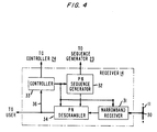
- FIG. 4 is an alternative arrangement of the receiver of FIG. 1.
- In accordance with the present invention, a lightwave communication system uses spread spectrum code-division-multiple-access (SS-CDMA) techniques along with wavelength-division-multiplexing (WDM), otherwise known as Frequency-Division-Multiplexing (FDM), to achieve a lightwave communication system which efficiently uses the available optical spectrum of the associated lightguide while providing adequate rejection of interference caused by one signal drifting into the bandwidth being used by another transmitter/receiver pair. The present invention can be used to implement, for example, a local area network capable of supporting thousands of simultaneous two-way communication channels at a relatively low data rate, e.g., 10 Mbit/sec each, with no blocking, no hierarchy, and no centralized control. Also, since the communication channels are supported in a time-parallel manner, extraordinary throughput can be achieved without requiring unreasonable hardware speed. The present network architecture can, therefore, also be used to realize a switching system capable of establishing thousands, or even tens of thousands, of high-data-rate (e.g., 10 Mbit/sec) interconnections.
- FIG. 1 is a block diagram of a preferred embodiment of the present optical communication system including an exemplary transceiver arrangement in accordance with the present invention, showing all possible elements even though certain elements can be combined or are optional. In FIG. 1, a plurality of N optical transceivers 10₁ to 10N are coupled to an optical waveguide arrangement 11, to permit communications between pairs of the
transceivers 10i, or between a transceiver and an external network via an optionalnetwork interface unit 12 where such inter-network communication is desired. Optical waveguide arrangement 11 can be any optical device that combines the light signals from all thetransmitters 13 of transceivers 10₁ to 10N, andnetwork interface 12 if present, and distributes the resulting superposition of signals among allreceivers 14 of the N transceivers, andnetwork interface 12, if present. In a preferred embodiment of the system, the optical waveguide arrangement 11 might consist of a large star coupler, with an input fiber from eachtransmitter 13, andnetwork interface 12 if present, and an output fiber to eachreceiver 14, andnetwork interface 12 if present. Alternative implementations might be as an optical bus or loop or any arrangement of optical devices that achieves the same function. - Each
transceiver 10i comprises atransmitter 13, for transmitting a signal from an associated system user over optical waveguide arrangement 11, and areceiver 14 which receives all WDM, SS-CDMA, signals propagating on optical waveguide arrangement 11 and de-spreads the desired WDM, SS-CDMA signal for delivery to the associated system user. - An
exemplary transmitter 13 in each oftransceivers 10i is shown in FIG. 1 as comprising alaser source 20 which has its signal modulated by a light modulatingmeans 21 internally or externally to source 20.Laser source 20 can be implemented by, for example, a semiconductor laser or any other suitable light source which is a coherent system that acts like an oscillator for generating a random carrier frequency. The lightwave signal oflaser source 20 is modulated by modulatingmeans 21 using any one of a variety of methods well-known in the art, including direct modulation of the laser current or external amplitude or phase modulation of the light. The modulating signal is either a digital or an analog signal from the associated system user. This results in an modulated output signal destined for another system user or to an external network, whennetwork interface 12 is present in the system. The modulated output signal from the directly or externally modulatedlaser source 20 is, therefore, an up-converted signal in a frequency band determined bylaser source 20 which is shown in FIG. 1 as being delivered to aspectrum spreading device 22 which for purposes hereinafter will be considered as a Pseudo-Noise (PN) scrambling means 22. - In PN scrambling means 22, a predetermined high-frequency pseudo-random noise code, generated by a
PN sequence generator 23 under the control of acontroller 24, further modulates the modulated information wave from thelaser source 20/light modulator 21 combination to produce an output signal that is spread over a greater bandwidth than the information wave from modulatedlaser source 20, using any well known spreading technique. The output signal from PN scrambling means 22 is coupled into optical waveguide arrangement 11 via any well-known optical coupling device. It is to be understood that the sequence oflaser source 20, light modulatingmeans 21 and PN scrambling means 22, as shown in FIG. 1, could be modified such that the light signal from the laser source could have its spectrum spread before modulating the resulting spread spectrum carrier signal with the user signal. It is to be further understood that PN scrambling means 22 andPN sequence generator 23 are but one spectrum spreading technique that could be used in practicing the present invention. Alternatively, PN scrambling means 22 andPN sequence generator 23 could be replaced by a Frequency-Hopping (FH) Code Generator 26 which is used to modulate the light beam oflaser source 20 and produce an output light beam wherein the output carrier frequency is hopped in a predetermined sequence. The Frequency-Hopping technique, as a spectrum spreading function, is well known in the art. Regardless of the spectrum spreading technique used, a (possibly attenuated) replica of the SS-CDMA output signal from atransmitter 13 appears at eachoutput 30 of optical waveguide arrangement 11 along with the SS-CDMA signals from all the other transmitters. An exemplary frequency spectrum of multiple WDM, SS-CDMA, signals, present at eachoutput 30 of optical waveguide arrangement 11 at any point in time, is shown in FIG. 2. - The signals propagating through optical waveguide arrangement 11 are received by each of
receivers 14 of transceivers 10₁ to 10N. In areceiver 14, the signal from optical waveguide arrangement 11 is received in a PN descrambling means 31 where the received WDM, SS-CDMA, signal, as shown in FIG. 2, is de-spread using a PN code sequence which is synchronized and matched to the PN code sequence used by apredetermined transmitter 13 of another one of transceivers 10₁ to 10N forming the two-way communication. The PN code sequence used by PN descrambling means 31 for de-spreading the received signal is obtained fromPN sequence generator 32 which is under the control ofcontroller 33. The de-spread signal at the output of PN descrambling means 31 can comprise the exemplary configuration shown in FIG. 3, where the desired signal appears as anarrowband signal 39 and the other received transmissions form a smooth low-level background across the spectrum and appear as noise. It must be understood that the desired signal will only appear as anarrowband signal 39 if the PN code sequences used by the associated transmitter and receiver are the same and synchronized in their application to the spreading and de-spreading operation. - The output signal from PN descrambling means 31 is delivered to a
narrowband receiver 34 which maintains itself locked to the narrowband signal of FIG. 3 by any suitable technique as, for example, Automatic Frequency Control (AFC), and demodulates the acquired signal to a corresponding analog or digital signal for transmission to the destined user vialead 35. It is to be understood thatnarrowband receiver 34 can be realized in a variety of ways, such as through the heterodyne or homodyne, detection or through external optical filters. - Where it is desired that the present system also has the capability of communicating with an external network, an
optional network interface 12 is connected to optical waveguide arrangement 11 via appropriate coupling means atpoints network interface 12 functions to convert signals between the external network format to that for transmission on optical waveguide arrangement 11 in any suitable manner. For purposes of discussion hereinafter,network interface 12 will not be included in the system description, but it is to be understood that if such interface were present, it would act in a manner similar to that described for any one of transceivers 10₁ to 10N for providing an appropriate 2-way communication link with the external network. - For the steady state operation, where various transmitters and receivers are already communicating with each other and there is no interest by any transmitter to acquire a 2-way communications link, an exemplary spectrum as shown in FIG. 2 would exist, less the dashed narrowband acquisition signals. Under such steady-state conditions, for each one-way communication link the
PN sequence generator 23 in the transmitter at one end of the link and thePN sequence generator 32 in the receiver at the other end of the link must maintain mutual synchronization in order to obtain thenarrowband signal 39 in the spectrum shown for the desired signal in FIG. 3. To achieve this, either thePN sequence generator 23 or thePM sequence generator 32 in eachtransceiver 10 must be "tunable" (i.e., programmable) to permit matching of its PN code sequence to that generated by the other PN sequence generator at the other end of the communication link. Furthermore, either thelaser source 20 of eachtransceiver 10 or thenarrowband receiver 34 of eachtransceiver 10 must tunable over the full frequency range of interest, in order to allow full network interconnectivity, i.e., any receiver can receive the signal from any transmitter. - A preferred arrangement would be to have each
narrowband receiver 34 at each of the transceivers selectively tunable to any frequency within a certain predetermined frequency range, while thelaser source 20 of eachtransceiver 10i is not tunable and generates an arbitrary or undetermined frequency which is not constrained in any way. Indeed, the oscillation frequency oflaser source 20 might even drift erratically and fall on top of the frequency generated by thelaser source 20 of another transceiver without any adverse effects on the communication links. The range of tunability of eachnarrowband receiver 34 must be large enough to include all the frequencies ofoil laser sources 20 present in the system. - It is understood that in the foregoing discussion the term "frequency" refers to the underlying optical carrier and is of the order of 230,000 GHz for a wavelength of 1.3 µm. The usage of frequency as a parameter instead of wavelength is motivated by the particular type of signal processing that makes frequency, and not wavelength, the important parameter. Additionally, in the above-mentioned preferred arrangement, it is also preferable that the
PN Sequence Generator 23 at the associatedtransmitter 13 be programmable to match a PN code sequence generated by thePN Sequence Generator 32 of a desiredreceiver 14 in anothertransceiver 10, but that thePN Sequence Generator 32 at thereceiver 14 would have to then be capable of synchronization to thePN Sequence Generator 23 attransmitter 13 of the link. It is to be understood that the present system is not limited to such preferred arrangement but that other permutations of the tunability oflaser sources 20,narrowband receivers 34, andPN Sequence Generators Controllers PN Sequence Generators narrowband receiver 34 as will be explained hereinafter. - In a start-up condition, which can occur at any time, a first and a second transceiver are attempting to gain access to each other for establishing a 2-way link between the associated users of the system while others are already communicating via optical waveguide arrangement 11 as described above for the steady state condition. To begin acquisition, one technique would be to have user "A", associated with, for example transceiver 10₁ notify its
controller 24, via a signaling message, that user "A" wishes to establish a link with user "B" associated with, for example,transceiver 10N.Controller 24 can comprise, for example, a simple microcomputer or other device which begins by disabling thePN sequence generator 23. As a result, the acquisition signal that user "A" transmits over optical waveguide arrangement 11 is not spectrally spread but, rather, it looks like the narrowband acquisition signals 40 and 41 shown in FIG. 2. This signal does not interfere with already established communication links which are using spread spectrum and, thereby, are immune to narrowband interference. -
Laser source 20 at transceiver 10₁ is modulated by an introductory message from user "A", which introductory message can comprise certain preamble information including the address of the calling transceiver (10₁) and the address of the called transceiver (10N). The modulated narrowband introductory signal is sent over optical waveguide arrangement 11 as a narrowband acquisition information signal centered on the carrier frequency generated bylaser source 20 of transceiver 10₁. This narrowband acquisition information signal fromtransmitter 13 of transceiver 10₁ appears as, for example, thenarrowband signal 40 in FIG. 2 when looking at the overall frequency spectrum of optical waveguide arrangement 11. Such narrowband acquisition signal is only transmitted by the calling transceiver during acquisition, which, generally, takes a small amount of time when compared to the time the communication link is maintained after acquisition has been completed. - Each of the
receivers 14 of transceivers 10₁ to 10N receives the narrowbandintroductory message 40 from transceiver 10₁ along with all other 2-way communications propagating on optical waveguide arrangement 11 from the already established communication links. If the calledtransceiver 10N is not already busy on another communication link, then under the control of itscontroller 33 ofreceiver 14, itsnarrowband receiver 34 is caused to continuously scan the frequency spectrum in order to detect a narrowband acquisition information signal similar to signal 40 of FIG. 2 somewhere in the spectrum of optical waveguide arrangement 11. When anexemplary signal 40 is received,controller 33 detects, via itsfeedback path 36, that such narrowband signal exists and causesnarrowband receiver 34 to lock onto the carrier frequency of the narrowband signal to permit decoding the message contained therein. If the address contained in the decoded acquisition information message corresponds to another transceiver, then this transceiver will unlock itsnarrowband receiver 34 and resume scanning the spectrum, repeating the above process until it obtains an acquisition information message indicating that this is the transceiver being called. - After locking onto an acquisition information signal and finding that the decoded acquisition information message indicates that the transceiver is being called,
controller 33 of the calledtransceiver 10N notifies the associatedcontroller 24 intransmitter 13 that the transceiver is being called by transceiver 10₁. Such notification causescontroller 24 to disablePN Sequence Generator 23 while sending a proper acquisition answer message to the light modulating means 21, which includes the addresses of the called and calling transceiver. Such action causestransmitter 13 oftransceiver 10N to transmit a narrowband acquisition answer signal, using the arbitrary or undetermined carrier frequency generated by itslaser source 20, onto optical waveguide arrangement 11. Such narrowband acquisition answer signal can take the exemplary form ofsignal 41 in FIG. 2, which is, in general, at a frequency different from that ofsignal 40. - While transceiver 10₁ is transmitting its narrowband acquisition information signal indicating it wishes to establish a 2-way call with
transceiver 10N,controller 33 of transceiver 10₁ is causing itsnarrowband receiver 34 to scan the spectrum looking for a narrowband signal such assignal 41 in FIG. 2. When it detects a narrowband signal, it causesnarrowband receiver 34 to lock onto the carrier of such narrowband signal and decodes the message therein to see if it is an answer signal fromtransceiver 10N. If the detected narrowband signal is other than an answer signal fromtransceiver 10N, thencontroller 33 of transceiver 10₁ unlocks itsnarrowband receiver 34 to continue the scanning and detection process. - Once transceiver 10₁ detects that the received narrowband signal is an answer signal from
transceiver 10N, a 2-way link is established since transceiver 10₁ is locked onto the carrier frequency of thelaser source 20 oftransceiver 10N, and vice versa, due to the two acquisition information signals. The next and final step consists of switching to spread-spectrum communication on the newly achieved two-way link by activatingPN scramblers 22 anddescramblers 31 at both ends of the link. The final step begins with the controllers at the two ends of the link exchanging information about the PN sequence to be used for scrambling. For example, each transmitter could send to thereceiver 14 at the other end the exact PN bit sequence to be used for descrambling. Alternatively, a short identifier or seed for generating the sequence could be sent. Such technique would allow the use of very long PN sequences without requiring the controllers to maintain a large directory of PN sequences in use in the system. - Next, the two transceivers must switch on their
PN scramblers 22 anddescramblers 31, and achieve pairwise synchronization of the associated PN code sequences. As soon asPN scramblers 22 are activated, the two narrowband acquisition signals 40 and 41, shown dashed in FIG. 2, disappear from optical waveguide arrangement 11 and are replaced by their spread-spectrum counterparts which look like the other signals already present on the waveguide arrangement 11, shown solid in FIG. 2. When proper synchronization of the PN sequence is achieved, the condition will be characterized by the appearance ofnarrowband signal 39 in the spectrum afterPN descrambler 31, as shown in FIG. 3. The two transceivers can coordinate the transition to PN scrambling and descrambling through the already-established two-way link, so that the PM sequences will be approximately synchronized when the transition takes place. Final adjustment of the synchronization can then be achieved quickly through a simple search procedure. For example,controller 33 directsPN sequence generator 32 to slowly advance or retard the position of the generated PN code untilnarrow signal 39 appears in the spectrum, indicating that proper synchronization has been achieved. The two-way link is now operating in the steady-state WDM, SS-CDMA transmission format. - If, however,
transceiver 10N is presently busy on a call, it will not be sweeping or scanning the frequency spectrum looking for an acquisition information signal, but will be locked onto an existing WDM, SS-CDMA signal forming a current 2-way communication. As a result no answer will be sent bytransceiver 10N back to transceiver 10₁ within a reasonable period of time, and user 1 is thereby notified that his call cannot presently be completed. - It is to be understood that the above described technique for acquiring a 2-way link is merely provided for exemplary purposes and not for purposes of limitation since other techniques can also be used. For example, if transceiver 10₁ wishes to establish a 2-way link with
transceiver 10N transceiver 10₁ can generate an acquisition information signal which is encoded with the (perhaps abbreviated) PN code sequence used bytransceiver 10N, rather than being a narrowband uncoded signal. The PN code sequence oftransceiver 10N can be easily determined from a look-up table in an associated memory ofcontroller 24 of transceiver 10₁. Meanwhile, eachreceiver 14 of all non-busy transceivers is sweeping or scanning the spectrum while changing the phase of its PN code sequence for each sweep of the spectrum by, for example, skipping one symbol. Within a short time, thePN Sequence Generator 32 atreceiver 14 oftransceiver 10N will detect anarrowband signal 39 as shown in FIG. 3, because thePN Sequence Generator 32 attransceiver 10N will become synchronized with thePN Sequence Generator 23 intransmitter 13 of transceiver 10₁ when the phase of the received PN code sequence matches the generated PN code sequence at PN descrambling means 31 oftransceiver 10N. At thispoint transceiver 10N is locked onto the frequency and is synchronized with the PN code sequence transmitted by transceiver 10₁. At such occurrence,transceiver 10N transmits an acquisition answer signal, which is also WDM, SS-CDMA, encoded, back to transceiver 10₁ where a similar process is repeated in transceiver 10₁ until both transceivers are frequency and PN code sequence locked. Then 2-way steady state communications can proceed. - Availability of timing could be an expeditious feature to provide. Otherwise, acquisition is two-dimensional (frequency and timing). Special signals marking the edges of the timing band could also be used to refresh bit and chip timing at the start of each frequency sweep. Thus the timing acquisition problem is mitigated so long as the hardware is kept stable enough to maintain timing during each sweep.
- It is to be understood that the above-described embodiments are simply illustrative of the invention. Various modifications and changes may be made by those skilled in the art.
For example, as shown in FIG. 4, thereceiver 14 can comprise the structure wherein the signal fromoutput 30 of waveguide arrangement 11 is received in thenarrowband receiver 31 where the received lightwave signal is converted into an electrical signal which is then de-scrambled in PN de-scrambler 34 using the PN sequence generated byPN sequence generator 32. Additionally, intransmitter 13,light modulator 21 and PN scrambling means can be interchanged or any one or both parts may be incorporated as part oflaser source 20.
Claims (3)
- A method of communicating by means of a plurality of lightwave signals transmitted over a lightwave waveguide arrangement, the method comprising the steps of:
at each of a plurality of lightwave transmitters,(a) generating a lightwave carrier,(b) modulating the lightwave carrier signal from step (a) with a separate information signal to be transmitted from a separate user;(c) spreading the optical spectrum of either one of (1) the lightwave carrier signal prior to performing step (b), or (2) the modulated lightwave signal obtained from step (b) using a reiterative encoding sequence which is different from reiterative encoding sequences used for spreading the optical spectrum of lightwave signals at other transmitters; and(d) coupling the modulated spread-spectrum signal obtained from step (c) onto the lightwave waveguide arrangement;CHARACTERIZED IN THAT
said lightwave carriers are at various undetermined wavelengths and IN THAT said communication employs wavelength-division multiplexing in combination with spread-spectrum code-division multiple-access whereby the spectrum spreading suppresses interference between different wavelength-division-multiplexed signals due to drift of the carrier wavelengths. - A method of communicating according to claim 1 including the further steps of:
at a first transceiver wanting to establish a 2-way link over the lightwave waveguide arrangement with a given one of a plurality of second transceivers,(e) performing steps (a), (c) and (d) using a acquisition signal including the identity of the first and the given one of the second transceivers; and
at each receiver associated with the first and the plurality of second transceivers not already busy on a 2-way link,(f) scanning the spectrum of the signal obtained from the lightwave waveguide arrangement for detecting a narrowband signal including an amplitude which is above a minimal amplitude;(g) in response to a detection of a narrowband signal in step (f), locking on to the carrier signal of the detected narrowband signal to establish a link from the first transceiver to the predetermined one of the plurality of second transceivers for a selective period of time. - A method of communicating according to claim 2, including the further steps of:
at a transmitter of the predetermined one of the plurality of second transceivers wherein the associated receiver has detected the narrowband signal according to step (g),(h) performing steps (a), (c) and (d) for transmitting an SS-CDMA acquisition information signal back to the first transceiver; and
at a receiver of the first transceiver,(i) performing steps (f) and (g) for establishing the link from the predetermined one of the plurality of second transceivers and the first transceiver.
Applications Claiming Priority (2)
| Application Number | Priority Date | Filing Date | Title |
|---|---|---|---|
| US834346 | 1986-02-28 | ||
| US06/834,346 US4703474A (en) | 1986-02-28 | 1986-02-28 | Spread spectrum code-division-multiple-access (SS-CDMA) lightwave communication system |
Publications (3)
| Publication Number | Publication Date |
|---|---|
| EP0240124A2 EP0240124A2 (en) | 1987-10-07 |
| EP0240124A3 EP0240124A3 (en) | 1990-10-24 |
| EP0240124B1 true EP0240124B1 (en) | 1994-05-11 |
Family
ID=25266717
Family Applications (1)
| Application Number | Title | Priority Date | Filing Date |
|---|---|---|---|
| EP87301415A Expired - Lifetime EP0240124B1 (en) | 1986-02-28 | 1987-02-19 | Lightwave communication system |
Country Status (5)
| Country | Link |
|---|---|
| US (1) | US4703474A (en) |
| EP (1) | EP0240124B1 (en) |
| JP (1) | JPS62206935A (en) |
| CA (1) | CA1245292A (en) |
| DE (1) | DE3789779T2 (en) |
Families Citing this family (119)
| Publication number | Priority date | Publication date | Assignee | Title |
|---|---|---|---|---|
| US7274652B1 (en) * | 2000-06-02 | 2007-09-25 | Conexant, Inc. | Dual packet configuration for wireless communications |
| DE3429454C1 (en) * | 1984-08-10 | 1999-03-11 | Siemens Ag | Relay point for wireless communication |
| US4901307A (en) * | 1986-10-17 | 1990-02-13 | Qualcomm, Inc. | Spread spectrum multiple access communication system using satellite or terrestrial repeaters |
| CA2064898A1 (en) * | 1987-01-27 | 1991-03-02 | Michael J. Yerbury | Spread-spectrum multiplexed transmission system |
| CA1293999C (en) * | 1987-08-24 | 1992-01-07 | Osamu Ichiyoshi | Earth station capable of effectively using a frequency band of asatellite |
| GB2220824A (en) * | 1988-07-13 | 1990-01-17 | Philips Electronic Associated | Transmission system for sending two signals simultaneously on the same communications channel |
| US4912722A (en) * | 1988-09-20 | 1990-03-27 | At&T Bell Laboratories | Self-synchronous spread spectrum transmitter/receiver |
| US4989199A (en) * | 1988-10-31 | 1991-01-29 | At&T Bell Laboratories | Photonic switch architecture utilizing code and wavelength multiplexing |
| US4930140A (en) * | 1989-01-13 | 1990-05-29 | Agilis Corporation | Code division multiplex system using selectable length spreading code sequences |
| JP2540935B2 (en) * | 1989-03-16 | 1996-10-09 | 日本電気株式会社 | Collective polarization control method |
| US5189683A (en) * | 1989-03-23 | 1993-02-23 | Echelon Corporation | Transceiver providing selectable frequencies and spreading sequences |
| US4979183A (en) * | 1989-03-23 | 1990-12-18 | Echelon Systems Corporation | Transceiver employing direct sequence spread spectrum techniques |
| US5357541A (en) * | 1989-03-23 | 1994-10-18 | Echelon Corporation | Transceiver providing selectable frequencies and spreading sequences |
| US4975926A (en) * | 1989-03-30 | 1990-12-04 | Guenther Knapp | Wireless indoor data communication system |
| US5022046A (en) * | 1989-04-14 | 1991-06-04 | The United States Of America As Represented By The Secretary Of The Air Force | Narrowband/wideband packet data communication system |
| US5016255A (en) * | 1989-08-07 | 1991-05-14 | Omnipoint Data Company, Incorporated | Asymmetric spread spectrum correlator |
| US5499265A (en) * | 1989-08-07 | 1996-03-12 | Omnipoint Data Company, Incorporated | Spread spectrum correlator |
| US5022047A (en) * | 1989-08-07 | 1991-06-04 | Omnipoint Data Corporation | Spread spectrum correlator |
| US5090024A (en) * | 1989-08-23 | 1992-02-18 | Intellon Corporation | Spread spectrum communications system for networks |
| US5005169A (en) * | 1989-11-16 | 1991-04-02 | Westinghouse Electric Corp. | Frequency division multiplex guardband communication system for sending information over the guardbands |
| JPH03214939A (en) * | 1990-01-19 | 1991-09-20 | Nec Corp | Channel identification reception method |
| US5212577A (en) * | 1990-01-19 | 1993-05-18 | Canon Kabushiki Kaisha | Optical communication equipment and optical communication method |
| EP0438155B1 (en) * | 1990-01-19 | 1997-05-02 | Canon Kabushiki Kaisha | Optical communication equipment |
| US5166952A (en) * | 1990-05-24 | 1992-11-24 | Cylink Corporation | Method and apparatus for the reception and demodulation of spread spectrum radio signals |
| US5253268A (en) * | 1990-05-24 | 1993-10-12 | Cylink Corporation | Method and apparatus for the correlation of sample bits of spread spectrum radio signals |
| US5157686A (en) * | 1990-05-24 | 1992-10-20 | Cylink Corporation | Method and apparatus for the modulation of spread spectrum radio signals |
| US5103459B1 (en) * | 1990-06-25 | 1999-07-06 | Qualcomm Inc | System and method for generating signal waveforms in a cdma cellular telephone system |
| US6693951B1 (en) * | 1990-06-25 | 2004-02-17 | Qualcomm Incorporated | System and method for generating signal waveforms in a CDMA cellular telephone system |
| EP0540664A4 (en) * | 1990-07-23 | 1993-06-09 | Omnipoint Corporation | Sawc phase-detection method and apparatus |
| US5081642A (en) * | 1990-08-06 | 1992-01-14 | Omnipoint Data Company, Incorporated | Reciprocal saw correlator method and apparatus |
| DE59009801D1 (en) * | 1990-08-28 | 1995-11-23 | Itt Ind Gmbh Deutsche | Remote control device with a spreading code transmission path. |
| WO1992007434A1 (en) | 1990-10-23 | 1992-04-30 | Omnipoint Corporation | Method and apparatus for establishing spread spectrum communications |
| US5535238A (en) | 1990-11-16 | 1996-07-09 | Interdigital Technology Corporation | Spread spectrum adaptive power control communications system and method |
| US6873643B2 (en) | 1990-11-16 | 2005-03-29 | Interdigital Technology Corporation | Spread spectrum adaptive power control communications system and method |
| US5299226A (en) * | 1990-11-16 | 1994-03-29 | Interdigital Technology Corporation | Adaptive power control for a spread spectrum communications system and method |
| US5703874A (en) | 1990-12-05 | 1997-12-30 | Interdigital Technology Corporation | Broadband CDMA overlay system and method |
| US5161168A (en) * | 1991-05-15 | 1992-11-03 | Scs Mobilecom, Inc. | Spread spectrum CDMA communications system microwave overlay |
| US5228056A (en) * | 1990-12-14 | 1993-07-13 | Interdigital Technology Corporation | Synchronous spread-spectrum communications system and method |
| US5506864A (en) | 1990-12-05 | 1996-04-09 | Interdigital Technology Corporation | CDMA communications and geolocation system and method |
| US5263045A (en) * | 1990-12-05 | 1993-11-16 | Interdigital Technology Corporation | Spread spectrum conference call system and method |
| US7020125B2 (en) * | 1990-12-05 | 2006-03-28 | Interdigital Technology Corporation | Broadband CDMA overlay system and method |
| US5185762A (en) * | 1991-05-15 | 1993-02-09 | Scs Mobilecom, Inc. | Spread spectrum microwave overlay with notch filter |
| US5351269A (en) * | 1990-12-05 | 1994-09-27 | Scs Mobilecom, Inc. | Overlaying spread spectrum CDMA personal communications system |
| US5274665A (en) * | 1990-12-14 | 1993-12-28 | Interdigital Technology Corporation | Polyopoly overlapping spread spectrum communication system and method |
| FR2672169B1 (en) * | 1991-01-24 | 1993-04-09 | Alcatel Nv | COMMUNICATION METHOD AND NETWORK ON OPTICAL FIBERS WITH FREQUENCY MULTIPLEXING. |
| US5166821A (en) * | 1991-03-12 | 1992-11-24 | General Instrument Corporation | Reduction of non-linear effects in optical fiber communication systems and method of using same |
| US5402413A (en) * | 1991-04-08 | 1995-03-28 | Omnipoint Corporation | Three-cell wireless communication system |
| US5694414A (en) * | 1991-05-13 | 1997-12-02 | Omnipoint Corporation | Multi-band, multi-mode spread-spectrum communication system |
| AU2140092A (en) * | 1991-05-13 | 1992-12-30 | Omnipoint Corporation | Dual mode transmitter and receiver |
| US5887020A (en) * | 1991-05-13 | 1999-03-23 | Omnipoint Corporation | Multi-band, multi-mode spread-spectrum communication system |
| US5790587A (en) * | 1991-05-13 | 1998-08-04 | Omnipoint Corporation | Multi-band, multi-mode spread-spectrum communication system |
| US5796772A (en) * | 1991-05-13 | 1998-08-18 | Omnipoint Corporation | Multi-band, multi-mode spread-spectrum communication system |
| US5815525A (en) * | 1991-05-13 | 1998-09-29 | Omnipoint Corporation | Multi-band, multi-mode spread-spectrum communication system |
| US5228053A (en) * | 1991-05-15 | 1993-07-13 | Interdigital Technology Corporation | Spread spectrum cellular overlay CDMA communications system |
| USRE38627E1 (en) * | 1991-05-15 | 2004-10-19 | Interdigital Technology Corp. | High capacity spread spectrum channel |
| US5166951A (en) * | 1991-05-15 | 1992-11-24 | Scs Mobilecom, Inc. | High capacity spread spectrum channel |
| US5164958A (en) * | 1991-05-22 | 1992-11-17 | Cylink Corporation | Spread spectrum cellular handoff method |
| US5235615A (en) * | 1991-05-22 | 1993-08-10 | Cylink Corporation | Spread spectrum method |
| US5285469A (en) | 1991-06-03 | 1994-02-08 | Omnipoint Data Corporation | Spread spectrum wireless telephone system |
| US5345467A (en) * | 1991-07-10 | 1994-09-06 | Interdigital Technology Corp. | CDMA cellular hand-off apparatus and method |
| US5258995A (en) * | 1991-11-08 | 1993-11-02 | Teknekron Communications Systems, Inc. | Wireless communication system |
| WO1993012597A1 (en) * | 1991-12-16 | 1993-06-24 | Omnipoint Corporation | Spread-spectrum data publishing system |
| US5276703A (en) * | 1992-01-13 | 1994-01-04 | Windata, Inc. | Wireless local area network communications system |
| US5307194A (en) * | 1992-03-24 | 1994-04-26 | Grumman Aerospace Corporation | Covert communication system using ultraviolet light |
| US5430759A (en) * | 1992-08-20 | 1995-07-04 | Nexus 1994 Limited | Low-power frequency-hopped spread spectrum reverse paging system |
| US5519526A (en) * | 1992-10-21 | 1996-05-21 | California Institute Of Technology | Optical protocols for communication networks |
| US5343494A (en) * | 1993-01-13 | 1994-08-30 | Motorola, Inc. | Code division multiple access (CDMA) inbound messaging system utilizing over-the-air programming |
| US5355389A (en) * | 1993-01-13 | 1994-10-11 | Omnipoint Corporation | Reciprocal mode saw correlator method and apparatus |
| US5436941A (en) * | 1993-11-01 | 1995-07-25 | Omnipoint Corporation | Spread spectrum spectral density techniques |
| US6094575A (en) * | 1993-11-01 | 2000-07-25 | Omnipoint Corporation | Communication system and method |
| US6005856A (en) * | 1993-11-01 | 1999-12-21 | Omnipoint Corporation | Communication protocol for spread spectrum wireless communication system |
| US6088590A (en) * | 1993-11-01 | 2000-07-11 | Omnipoint Corporation | Method and system for mobile controlled handoff and link maintenance in spread spectrum communication |
| US5742583A (en) | 1994-11-03 | 1998-04-21 | Omnipoint Corporation | Antenna diversity techniques |
| US20050225860A1 (en) * | 1995-03-13 | 2005-10-13 | Thomas Mossberg | Segmented complex diffraction gratings |
| US6018317A (en) * | 1995-06-02 | 2000-01-25 | Trw Inc. | Cochannel signal processing system |
| US5802046A (en) * | 1995-06-05 | 1998-09-01 | Omnipoint Corporation | Efficient time division duplex communication system with interleaved format and timing adjustment control |
| US5959980A (en) | 1995-06-05 | 1999-09-28 | Omnipoint Corporation | Timing adjustment control for efficient time division duplex communication |
| US5689502A (en) * | 1995-06-05 | 1997-11-18 | Omnipoint Corporation | Efficient frequency division duplex communication system with interleaved format and timing adjustment control |
| US5745484A (en) * | 1995-06-05 | 1998-04-28 | Omnipoint Corporation | Efficient communication system using time division multiplexing and timing adjustment control |
| US6678311B2 (en) | 1996-05-28 | 2004-01-13 | Qualcomm Incorporated | High data CDMA wireless communication system using variable sized channel codes |
| US5926500A (en) * | 1996-05-28 | 1999-07-20 | Qualcomm Incorporated | Reduced peak-to-average transmit power high data rate CDMA wireless communication system |
| US6396804B2 (en) | 1996-05-28 | 2002-05-28 | Qualcomm Incorporated | High data rate CDMA wireless communication system |
| US5930230A (en) | 1996-05-28 | 1999-07-27 | Qualcomm Incorporated | High data rate CDMA wireless communication system |
| US5867290A (en) * | 1996-11-19 | 1999-02-02 | Rdl Commercial Technologies Corporation | High capacity spread spectrum optical communications system |
| DE19722370A1 (en) | 1997-05-28 | 1998-12-03 | Alsthom Cge Alcatel | Receiver for an optical communication system and method for its operation |
| DE19725714C1 (en) * | 1997-06-18 | 1998-12-17 | Deutsche Telekom Ag | Method for the optical transmission of signaling and control information in optical networks |
| DE19822616A1 (en) * | 1998-05-20 | 1999-11-25 | Sel Alcatel Ag | Light source and method for the transmission of spectrally coded data |
| DE19833549A1 (en) * | 1998-07-25 | 2000-01-27 | Sel Alcatel Ag | Receiver for use in a transmission system for spectrally coded data and a method |
| US6236483B1 (en) | 1998-07-30 | 2001-05-22 | Codestream Technologies Corporation | Optical CDMA system using sub-band coding |
| US6771935B1 (en) * | 1998-10-05 | 2004-08-03 | Alcatel | Wireless bus |
| US7065298B1 (en) | 1998-11-17 | 2006-06-20 | Intel Corporation | Code-based optical networks, methods, and apparatus |
| DE19904940A1 (en) * | 1999-02-06 | 2000-12-21 | Sel Alcatel Ag | Optical transmission system as well as transmitter and receiver |
| US6947469B2 (en) | 1999-05-07 | 2005-09-20 | Intel Corporation | Method and Apparatus for wireless spread spectrum communication with preamble processing period |
| US6845087B1 (en) | 1999-09-20 | 2005-01-18 | Northrop Grumman Corporation | Wideband wireless communications architecture |
| US6865344B1 (en) * | 1999-11-12 | 2005-03-08 | Intel Corporation | Code-switched optical networks |
| US6313771B1 (en) | 1999-11-17 | 2001-11-06 | Templex Technology, Inc. | Codes, methods, and apparatus for optical encoding and decoding |
| US20020024693A1 (en) * | 2000-05-02 | 2002-02-28 | Eliezer Manor | Optical frequency division multiplexing |
| US7095961B2 (en) * | 2000-09-19 | 2006-08-22 | Fujitsu Limited | Optical communication system and optical receiver |
| EP1383490B1 (en) * | 2001-03-14 | 2012-04-25 | Bristol-Myers Squibb Company | Combination of an epothilone analog and chemotherapeutic agents for the treatment of proliferative diseases |
| US8174394B2 (en) * | 2001-04-11 | 2012-05-08 | Trutouch Technologies, Inc. | System for noninvasive determination of analytes in tissue |
| US8581697B2 (en) | 2001-04-11 | 2013-11-12 | Trutouch Technologies Inc. | Apparatuses for noninvasive determination of in vivo alcohol concentration using raman spectroscopy |
| US20040197107A1 (en) * | 2001-05-01 | 2004-10-07 | Habib Fathallah | Method for the ocdma encoding of optical signals |
| US20020170591A1 (en) * | 2001-05-15 | 2002-11-21 | Pharmaseq, Inc. | Method and apparatus for powering circuitry with on-chip solar cells within a common substrate |
| JP2002374210A (en) * | 2001-06-15 | 2002-12-26 | Sumitomo Electric Ind Ltd | Optical communication system |
| WO2003003601A1 (en) * | 2001-06-29 | 2003-01-09 | Nokia Corporation | Method and apparatus for an optical cdma system |
| FR2827971B1 (en) * | 2001-07-27 | 2003-10-10 | Thales Sa | MULTI-USER OPTICAL COMMUNICATIONS NETWORK, LOW LATENCY RECONFIGURABLE |
| ITPD20010205A1 (en) * | 2001-08-09 | 2003-02-09 | Infm Istituto Naz Per La Fi Si | EQUIPMENT AND METHOD OF NON-INVASIVE MEASUREMENT OF PARAMETERS RELATIVE TO ORGANIC FABRICS THROUGH SPECTROSCOPY IN PARTICULAR INFRAR LIGHT |
| EP1309116A1 (en) * | 2001-11-02 | 2003-05-07 | Alcatel | Bidirectional coding splitter |
| JP4419391B2 (en) * | 2003-01-09 | 2010-02-24 | 沖電気工業株式会社 | Transmission medium access control system and relay side terminal device |
| US8515506B2 (en) | 2004-05-24 | 2013-08-20 | Trutouch Technologies, Inc. | Methods for noninvasive determination of in vivo alcohol concentration using Raman spectroscopy |
| US8730047B2 (en) | 2004-05-24 | 2014-05-20 | Trutouch Technologies, Inc. | System for noninvasive determination of analytes in tissue |
| DE602005024141D1 (en) * | 2004-08-20 | 2010-11-25 | Panasonic Corp | OPTICAL DEVICE FOR MULTIMODE TRANSMISSION |
| JP4561403B2 (en) * | 2005-02-25 | 2010-10-13 | 沖電気工業株式会社 | Optical division multiplexing transmission / reception method and optical division multiplexing transmission / reception apparatus |
| JP4548324B2 (en) * | 2005-12-02 | 2010-09-22 | 沖電気工業株式会社 | 1-to-N communication system, synchronization establishment method, and synchronization tracking method |
| US20100074444A1 (en) * | 2008-06-26 | 2010-03-25 | Telcordia Technologies, Inc. | Method and System for OCDM-Based Photonic Layer Security Robustness to Spoof Data Integrity |
| WO2010040377A1 (en) * | 2008-10-06 | 2010-04-15 | Nokia Siemens Networks Oy | Optical component and method for data processing |
| WO2012003292A1 (en) * | 2010-07-01 | 2012-01-05 | Analysis First LLC | Identification and communication systems |
| US9124462B2 (en) | 2012-10-25 | 2015-09-01 | Texas Instruments Incorporated | Flexible PRBS architecture for a transceiver |
| EP3282597A1 (en) | 2016-08-12 | 2018-02-14 | Fraunhofer-Gesellschaft zur Förderung der angewandten Forschung e.V. | Communication system and transmitter |
Family Cites Families (15)
| Publication number | Priority date | Publication date | Assignee | Title |
|---|---|---|---|---|
| US3605018A (en) * | 1968-09-13 | 1971-09-14 | Sylvania Electric Prod | Interference suppression in a receiver by envelope variation modulation |
| US4209689A (en) * | 1969-06-04 | 1980-06-24 | Hughes Aircraft Company | Laser secure communications system |
| US4112372A (en) * | 1977-01-11 | 1978-09-05 | Texas Instruments Incorporated | Spread spectrum communication system |
| US4164628A (en) * | 1977-06-06 | 1979-08-14 | International Telephone And Telegraph Corporation | Processor for multiple, continuous, spread spectrum signals |
| US4285060A (en) * | 1978-02-28 | 1981-08-18 | Harris Corporation | Spread spectrum code tracking loop |
| JPS5514752A (en) * | 1978-07-17 | 1980-02-01 | Nippon Telegr & Teleph Corp <Ntt> | Light multiple transmission system |
| FR2467512A1 (en) * | 1979-10-15 | 1981-04-17 | Crouzet Sa | INTEGRAL SIMULTANEOUS MULTI-ACCESS TRANSMISSION SYSTEM ON OPTICAL FIBER TRANSMISSION LINES |
| JPS56103557A (en) * | 1980-01-21 | 1981-08-18 | Matsushita Electric Ind Co Ltd | Receiving device |
| JPS5783942A (en) * | 1980-11-12 | 1982-05-26 | Mitsubishi Electric Corp | Analog signal transmitter |
| US4467468A (en) * | 1981-12-28 | 1984-08-21 | At&T Bell Laboratories | Optical communication system |
| GB2125253B (en) * | 1982-07-27 | 1985-09-11 | Standard Telephones Cables Ltd | Data communications system |
| GB2125654B (en) * | 1982-08-13 | 1986-01-29 | Hazeltine Corp | Intranetwork code division multiple access communication system |
| US4460992A (en) * | 1982-11-04 | 1984-07-17 | The United States Of America As Represented By The Secretary Of The Army | Orthogonal CDMA system utilizing direct sequence pseudo noise codes |
| US4470138A (en) * | 1982-11-04 | 1984-09-04 | The United States Of America As Represented By The Secretary Of The Army | Non-orthogonal mobile subscriber multiple access system |
| JPS6016038A (en) * | 1983-07-08 | 1985-01-26 | Hitachi Ltd | Optical radio communication equipment |
-
1986
- 1986-02-28 US US06/834,346 patent/US4703474A/en not_active Expired - Lifetime
-
1987
- 1987-02-10 CA CA000529338A patent/CA1245292A/en not_active Expired
- 1987-02-19 EP EP87301415A patent/EP0240124B1/en not_active Expired - Lifetime
- 1987-02-19 DE DE3789779T patent/DE3789779T2/en not_active Expired - Fee Related
- 1987-02-28 JP JP62044158A patent/JPS62206935A/en active Pending
Non-Patent Citations (1)
| Title |
|---|
| NEC Research and Development, No. 71, October 1983, pages 48 to 57 * |
Also Published As
| Publication number | Publication date |
|---|---|
| US4703474A (en) | 1987-10-27 |
| DE3789779T2 (en) | 1994-10-27 |
| JPS62206935A (en) | 1987-09-11 |
| CA1245292A (en) | 1988-11-22 |
| EP0240124A2 (en) | 1987-10-07 |
| DE3789779D1 (en) | 1994-06-16 |
| EP0240124A3 (en) | 1990-10-24 |
Similar Documents
| Publication | Publication Date | Title |
|---|---|---|
| EP0240124B1 (en) | Lightwave communication system | |
| US6922431B1 (en) | Communication using spread spectrum methods over optical fibers | |
| US5519526A (en) | Optical protocols for communication networks | |
| US5760941A (en) | System and method for performing optical code division multiple access communication using bipolar codes | |
| Foschini et al. | Using spread-spectrum in a high-capacity fiber-optic local network | |
| Shah | Optical code division multiple access | |
| US7200342B2 (en) | Direct-sequence spread-spectrum optical-frequency-shift-keying code-division-multiple-access communication system | |
| Ahn et al. | A symmetric-structure CDMA-PON system and its implementation | |
| Parham et al. | Code division multiple-access techniques for use in optical-fibre local-area networks | |
| EP0438155B1 (en) | Optical communication equipment | |
| Hickey et al. | The STARNET coherent WDM computer communication network: Experimental transceiver employing a novel modulation format | |
| Karafolas et al. | Optical CDMA system using bipolar codes and based on narrow passband optical filtering and direct detection | |
| JP4014770B2 (en) | Optical transmission system and optical transmission method | |
| Perrier et al. | Wavelength‐division integration of services in fibre‐optic networks | |
| JPH04335724A (en) | Coherent light transmission reception method | |
| Kiasaleh | Fiber optic frequency hopping multiple access communication system | |
| Su et al. | Performance of WDMA networks with baseband data packets and subcarrier multiplexed control channels | |
| Kavehrad et al. | An experiment on a CDM subcarrier multiplexed optical-fiber local area network | |
| Yamamoto et al. | Reduction of optical beat interference in passive optical networks using CDMA technique | |
| Nirmalathas et al. | Millimeter-wave fiber-wireless access systems incorporating wavelength division multiplexing | |
| Cooper et al. | Phase and polarization diversity for minimum MAI in OCDMA networks | |
| Karafolas et al. | Local area network communications using optical spread spectrum and serial correlation of bipolar codes | |
| Feldman et al. | Effect of optical beat interference on the dynamic range of a subcarrier multiple access passive optical network using Fabry-Perot lasers | |
| Lam et al. | Fast-wavelength-hopped CDMA system for secure optical communications | |
| Zacharias et al. | OFDM Modulated Full-Duplex WDM-ROF System |
Legal Events
| Date | Code | Title | Description |
|---|---|---|---|
| PUAI | Public reference made under article 153(3) epc to a published international application that has entered the european phase |
Free format text: ORIGINAL CODE: 0009012 |
|
| AK | Designated contracting states |
Kind code of ref document: A2 Designated state(s): DE GB |
|
| PUAL | Search report despatched |
Free format text: ORIGINAL CODE: 0009013 |
|
| AK | Designated contracting states |
Kind code of ref document: A3 Designated state(s): DE GB |
|
| 17P | Request for examination filed |
Effective date: 19901212 |
|
| 17Q | First examination report despatched |
Effective date: 19920513 |
|
| GRAA | (expected) grant |
Free format text: ORIGINAL CODE: 0009210 |
|
| AK | Designated contracting states |
Kind code of ref document: B1 Designated state(s): DE GB |
|
| REF | Corresponds to: |
Ref document number: 3789779 Country of ref document: DE Date of ref document: 19940616 |
|
| RAP4 | Party data changed (patent owner data changed or rights of a patent transferred) |
Owner name: AT&T CORP. |
|
| PLBE | No opposition filed within time limit |
Free format text: ORIGINAL CODE: 0009261 |
|
| STAA | Information on the status of an ep patent application or granted ep patent |
Free format text: STATUS: NO OPPOSITION FILED WITHIN TIME LIMIT |
|
| 26N | No opposition filed | ||
| PGFP | Annual fee paid to national office [announced via postgrant information from national office to epo] |
Ref country code: GB Payment date: 19980109 Year of fee payment: 12 |
|
| PG25 | Lapsed in a contracting state [announced via postgrant information from national office to epo] |
Ref country code: GB Free format text: LAPSE BECAUSE OF NON-PAYMENT OF DUE FEES Effective date: 19990219 |
|
| GBPC | Gb: european patent ceased through non-payment of renewal fee |
Effective date: 19990219 |
|
| PGFP | Annual fee paid to national office [announced via postgrant information from national office to epo] |
Ref country code: DE Payment date: 20020328 Year of fee payment: 16 |
|
| PG25 | Lapsed in a contracting state [announced via postgrant information from national office to epo] |
Ref country code: DE Free format text: LAPSE BECAUSE OF NON-PAYMENT OF DUE FEES Effective date: 20030902 |