EP0240034A1 - External fixation for osteosynthesis - Google Patents
External fixation for osteosynthesis Download PDFInfo
- Publication number
- EP0240034A1 EP0240034A1 EP87105092A EP87105092A EP0240034A1 EP 0240034 A1 EP0240034 A1 EP 0240034A1 EP 87105092 A EP87105092 A EP 87105092A EP 87105092 A EP87105092 A EP 87105092A EP 0240034 A1 EP0240034 A1 EP 0240034A1
- Authority
- EP
- European Patent Office
- Prior art keywords
- clamping
- screw
- fixator according
- actuating
- cylindrical holding
- Prior art date
- Legal status (The legal status is an assumption and is not a legal conclusion. Google has not performed a legal analysis and makes no representation as to the accuracy of the status listed.)
- Granted
Links
- 210000000988 bone and bone Anatomy 0.000 claims abstract description 54
- 239000004033 plastic Substances 0.000 claims description 14
- 229920003023 plastic Polymers 0.000 claims description 14
- 239000000463 material Substances 0.000 claims description 7
- 238000002347 injection Methods 0.000 claims description 5
- 239000007924 injection Substances 0.000 claims description 5
- 238000005553 drilling Methods 0.000 claims description 2
- 230000004913 activation Effects 0.000 abstract 2
- 210000002414 leg Anatomy 0.000 description 12
- 210000002303 tibia Anatomy 0.000 description 6
- 230000008901 benefit Effects 0.000 description 5
- 230000004323 axial length Effects 0.000 description 3
- 239000004917 carbon fiber Substances 0.000 description 2
- 239000003365 glass fiber Substances 0.000 description 2
- OKTJSMMVPCPJKN-UHFFFAOYSA-N Carbon Chemical compound [C] OKTJSMMVPCPJKN-UHFFFAOYSA-N 0.000 description 1
- 229920000049 Carbon (fiber) Polymers 0.000 description 1
- 229910000831 Steel Inorganic materials 0.000 description 1
- 229910052799 carbon Inorganic materials 0.000 description 1
- 239000004918 carbon fiber reinforced polymer Substances 0.000 description 1
- 238000010276 construction Methods 0.000 description 1
- 239000000109 continuous material Substances 0.000 description 1
- 230000008878 coupling Effects 0.000 description 1
- 238000010168 coupling process Methods 0.000 description 1
- 238000005859 coupling reaction Methods 0.000 description 1
- 230000005489 elastic deformation Effects 0.000 description 1
- 210000003414 extremity Anatomy 0.000 description 1
- 239000000835 fiber Substances 0.000 description 1
- 239000007943 implant Substances 0.000 description 1
- 230000006872 improvement Effects 0.000 description 1
- 238000003780 insertion Methods 0.000 description 1
- 230000037431 insertion Effects 0.000 description 1
- 238000004519 manufacturing process Methods 0.000 description 1
- 239000002184 metal Substances 0.000 description 1
- VNWKTOKETHGBQD-UHFFFAOYSA-N methane Chemical compound C VNWKTOKETHGBQD-UHFFFAOYSA-N 0.000 description 1
- 230000004048 modification Effects 0.000 description 1
- 238000012986 modification Methods 0.000 description 1
- 239000002991 molded plastic Substances 0.000 description 1
- 210000004197 pelvis Anatomy 0.000 description 1
- 230000000750 progressive effect Effects 0.000 description 1
- 239000011343 solid material Substances 0.000 description 1
- 230000007480 spreading Effects 0.000 description 1
- 239000010959 steel Substances 0.000 description 1
Images


Classifications
-
- A—HUMAN NECESSITIES
- A61—MEDICAL OR VETERINARY SCIENCE; HYGIENE
- A61B—DIAGNOSIS; SURGERY; IDENTIFICATION
- A61B17/00—Surgical instruments, devices or methods, e.g. tourniquets
- A61B17/56—Surgical instruments or methods for treatment of bones or joints; Devices specially adapted therefor
- A61B17/58—Surgical instruments or methods for treatment of bones or joints; Devices specially adapted therefor for osteosynthesis, e.g. bone plates, screws, setting implements or the like
- A61B17/60—Surgical instruments or methods for treatment of bones or joints; Devices specially adapted therefor for osteosynthesis, e.g. bone plates, screws, setting implements or the like for external osteosynthesis, e.g. distractors, contractors
- A61B17/64—Devices extending alongside the bones to be positioned
- A61B17/6466—Devices extending alongside the bones to be positioned with pin-clamps movable along a solid connecting rod
-
- A—HUMAN NECESSITIES
- A61—MEDICAL OR VETERINARY SCIENCE; HYGIENE
- A61B—DIAGNOSIS; SURGERY; IDENTIFICATION
- A61B17/00—Surgical instruments, devices or methods, e.g. tourniquets
- A61B17/56—Surgical instruments or methods for treatment of bones or joints; Devices specially adapted therefor
- A61B17/58—Surgical instruments or methods for treatment of bones or joints; Devices specially adapted therefor for osteosynthesis, e.g. bone plates, screws, setting implements or the like
- A61B17/60—Surgical instruments or methods for treatment of bones or joints; Devices specially adapted therefor for osteosynthesis, e.g. bone plates, screws, setting implements or the like for external osteosynthesis, e.g. distractors, contractors
- A61B17/64—Devices extending alongside the bones to be positioned
- A61B17/645—Devices extending alongside the bones to be positioned comprising a framework
-
- F—MECHANICAL ENGINEERING; LIGHTING; HEATING; WEAPONS; BLASTING
- F16—ENGINEERING ELEMENTS AND UNITS; GENERAL MEASURES FOR PRODUCING AND MAINTAINING EFFECTIVE FUNCTIONING OF MACHINES OR INSTALLATIONS; THERMAL INSULATION IN GENERAL
- F16B—DEVICES FOR FASTENING OR SECURING CONSTRUCTIONAL ELEMENTS OR MACHINE PARTS TOGETHER, e.g. NAILS, BOLTS, CIRCLIPS, CLAMPS, CLIPS OR WEDGES; JOINTS OR JOINTING
- F16B43/00—Washers or equivalent devices; Other devices for supporting bolt-heads or nuts
- F16B43/02—Washers or equivalent devices; Other devices for supporting bolt-heads or nuts with special provisions for engaging surfaces which are not perpendicular to a bolt axis or do not surround the bolt
-
- F—MECHANICAL ENGINEERING; LIGHTING; HEATING; WEAPONS; BLASTING
- F16—ENGINEERING ELEMENTS AND UNITS; GENERAL MEASURES FOR PRODUCING AND MAINTAINING EFFECTIVE FUNCTIONING OF MACHINES OR INSTALLATIONS; THERMAL INSULATION IN GENERAL
- F16B—DEVICES FOR FASTENING OR SECURING CONSTRUCTIONAL ELEMENTS OR MACHINE PARTS TOGETHER, e.g. NAILS, BOLTS, CIRCLIPS, CLAMPS, CLIPS OR WEDGES; JOINTS OR JOINTING
- F16B7/00—Connections of rods or tubes, e.g. of non-circular section, mutually, including resilient connections
- F16B7/04—Clamping or clipping connections
- F16B7/044—Clamping or clipping connections for rods or tubes being in angled relationship
- F16B7/048—Clamping or clipping connections for rods or tubes being in angled relationship for rods or for tubes without using the innerside thereof
- F16B7/0493—Clamping or clipping connections for rods or tubes being in angled relationship for rods or for tubes without using the innerside thereof forming a crossed-over connection
-
- A—HUMAN NECESSITIES
- A61—MEDICAL OR VETERINARY SCIENCE; HYGIENE
- A61B—DIAGNOSIS; SURGERY; IDENTIFICATION
- A61B17/00—Surgical instruments, devices or methods, e.g. tourniquets
- A61B17/16—Bone cutting, breaking or removal means other than saws, e.g. Osteoclasts; Drills or chisels for bones; Trepans
- A61B17/17—Guides or aligning means for drills, mills, pins or wires
- A61B17/171—Guides or aligning means for drills, mills, pins or wires for external fixation
Definitions
- the invention relates to an external fixator for osteosynthesis, as described in the preamble of claim 1 and in the book “Current Concepts of External Fixation of Fractures”, published by Uhthoff and Stahl, published by Springer-Verlag Berlin Heidelberg New York 1982, s. there 99-103, is known.
- the known fixator contains two approximately circular cylindrical steel disks of the same circumference, which are coaxially penetrated by a common clamping screw. A thin friction disk can optionally be provided in the joint between the two clamping disks.
- a clamping disk of the pair of clamping disks has two approximately cylindrical bores which extend secantially and parallel to one another and penetrate the radial circular end face facing the adjacent clamping disk. This results in two receiving bores slotted longitudinally over a relatively large circumferential area, into which the fixator rods - projecting from the longitudinal slots on one side along the longitudinal side - have to be inserted axially.
- the cylindrical holding openings for receiving either a bone nail (e.g. one Steinmann-Nagels) or a bone screw (for example a Schanze screw) are also formed in the known fixator analogous to the described cylindrical bores for the fixator rods as one-sided longitudinally slotted cylindrical bores.
- a jamming of a fixator rod and a bone screw occurs in the known external fixator accordingly by tightening the central clamping screw in such a way that both clamping disks with their facing circular end faces are pressed axially against each other and thereby clamp the circumferential regions of the fixator rod and bone screw protruding from the longitudinal slots of the receiving bores between them.
- fixator external which is known from the book “Current Concepts of External Fixation of Fractures”, offers the advantage of a simple design comprising only a few components, as opposed to other fixators who are known from prior use, but is regarding its handling during the operation and the subsequent supply of the Patients in need of improvement.
- the invention lies on the basis of the external fixator described in the book "Current Concepts of External Fixation of Fractures" the task of improving the known external fixator in terms of handling while maintaining its advantageous simple design. This object is achieved in accordance with the characterizing part of claim 1.
- each cylindrical holding opening is formed by a one-piece connected reveal surface, which can be deformed elastically or plastically to such an extent by actuating a screw element that the cylindrical holding opening initially leading as a drilling or screwing gauge and - after progressive infeed or narrowing - as a clamping receptacle for the bone nail or for the bone screw.
- the first possibility of such an alternative according to the invention may consist in the fact that the cylindrical holding openings, when the actuating screws are tightened by elastic or plastic material deformation with respect to the bridging component, are initially deliverable in the sense of a pre-locking and each with an additional feed stroke of one
- the drill or screw guide can be deformed up to its end-of-jamming position with the bone nail or with the bone screw.
- the second possibility of such an alternative may be that the cylindrical holding openings, when the actuating screws are tightened, together with the adjacent holder-side clamping jaw surfaces by means of elastic or plastic material deformation, are initially deliverable in the sense of a pre-locking (with regard to the bridging component) and that the cylindrical ones Each of the holding openings can be deformed with an additional feed stroke that also locks the clamping jaw surfaces, from a drill or screw guide to its end-of-jamming position with the bone nail or with the bone screw.
- a preferred embodiment according to the invention can therefore advantageously be handled in practice as follows: a cylindrical holding opening is pre-locked - if appropriate together with adjacent jaw surfaces - by partially tightening the actuating screw. This means that the holder on the bridging component (e.g. on a fixation rod) is held essentially immovable and the cylindrical holding opening is positioned essentially immovably with respect to the bridging component or with respect to the holder carrying it.
- a bone drill (hereinafter, if necessary, a tap) and, after removing the bone or tap, a bone screw or a bone nail (the latter as an implant) can then be inserted through the cylindrical holding opening. As soon as the bone nail or the bone screw is fastened through the cylindrical holding opening and is in its end position within the bone, the rest of the delivery of the cylindrical holding opening takes place until it jams.
- fixator according to the invention represents a significant simplification in operational terms compared to the known.
- an external fixator is particularly advantageous if both the cylindrical holding opening (for successively receiving a drill and a bone screw or a bone nail) and the jaw surfaces of the associated holder are used with a single actuating screw, from the pre-locking to the end position locking , can be operated.
- the actuating screws can be designed as toggle screws provided with manually operable large handling surfaces.
- An elastic or plastic deformation of the cylindrical holding opening - optionally together with adjacent jaw surfaces for the bridging component - can be advantageously carried out if the components involved in the delivery consist of a suitable plastic.
- Such a plastic can be processed into an injection molded plastic part and in particular can be reinforced with carbon fiber or glass fiber.
- the use of plastics - possibly including the bridging components - in addition to simplifying and reducing the cost of manufacture and a lightweight construction, creates a desirable X-ray transparency, which is not the case with the metal fixators previously used.
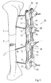
- an entire external fixator is designated by the reference number 10.
- the external fixator is shown using the example of a tibia designated T, in which F distance osteosynthesis is performed.
- the fixator 10 has two fixator rods 11 which are clamped in four brackets 12.
- Each holder 12 is provided with clamping jaw surfaces 13 for receiving the fixator rods 11.
- Components are provided for receiving the bone screws 15, as are shown, for example, in FIGS. 15 and 16. These components include washers 17, which are used for the spatial alignment of the bone screws 15.
- the rotatable washers 17 are provided in the region of their spherical surface 16 with an elongated hole 18 for receiving the screw shaft, not shown, of the actuating screw 14, which in turn contains the bone screw 15.
- the relative position of the brackets 12 on the bridging components is brought about by partially tightening the actuating screw 14 in question with its manual actuation knob 19. This partial suit also pre-locks the longitudinal axis y of each actuating screw in a desired spatial position.
- a bone drill is then axially passed through the front opening 20 (which merges into the cylindrical holding opening, not shown) of the actuating screw 14 in question, and the holding hole B is introduced into the tibia.
- a tap is then inserted through the opening 20 of the actuating screw 14 and the bone bore B is provided with an internal thread.
- the bone screw 15 is then inserted through the opening 20 of the actuating screw 14.
- the actuating screw 14 in question is manually used by means of the actuating knob 19.
- both the holder 12 on the associated fixator rod 11 and the bone screw 15 within the actuating screw 14 and finally also the space joint system (of which only the washer 17 is shown in FIG. 1) are relative to the fixator rod 11 firmly locked.
- the components shown there can also be used to create a frame fixator or a fixator in the manner of a spatial framework.
- additional brackets 12, not shown would be clamped on one side to the two fixator rods 11 and would serve as coupling members for further laterally adjacent fixator rods 11, not shown.
- holders 12 (with actuating screws 14) can also be arranged on diametrically opposite sides of the tibia T for holding Steinmann nails.
- the use of the fixator 10 is of course not limited to a tibia T, but is advantageously also possible with other extremities and the pelvis, possibly also across joints.
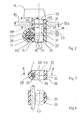
- the two-part holder 12 a has two clamps 21, 22.
- Each clamp 21, 22 has two mutually parallel clamp legs 23, 24 and 25, 26. Each two clamp legs 23, 24 and 25, 26 are connected to one another by a slotted tube region 27, 28.
- the slit tube region 27 of the clamp 22 forms the jaw surface 13 for the fixator rod 11 made of carbon fiber reinforced plastic.
- a slit sleeve 29 can be inserted into the jaw surface 13 to compensate for an undersize of the fixator rod.
- the slotted sleeve 29 accordingly forms a circumferentially variable fitting sleeve.
- the other clamp 21 contains the cylindrical holding opening 30 for receiving the bone screw 15.
- clamps 21 and 22 which each have only one slotted tube region 27 or 28, end of their two clamp legs 23, 24; 25, 26 are connected to one another in a one-piece, materially integral manner via a material bridge 31, 32.
- the material bridges 31, 32 serve to achieve defined clamping conditions.
- clamping legs 25, 26, 23, 24 Of the four successive clamping legs 25, 26, 23, 24, three clamping legs 25, 26, 23 each have a smooth through hole 33, 34, 35 and one clamping leg 24 has an internally threaded bore 36 for the threaded part 37 of the common actuating screw 14, which is used in the Embodiment according to FIGS. 2-4 the zylin dhariting opening 30 itself does not form.
- both the jaw surface 13 and the cylindrical holding bore 30 are operated together via the actuating screw 14.
- a pre-locking of the holder 12 a with respect to the fixator rod 11 and the bone screw 15 or with respect to a drill (not shown) is possible. Only when the actuating screw 14 is further pulled together does a fixed end position clamping of the fixator rod 11 occur with respect to the clamping jaw surface 13 or with respect to the slotted sleeve 29 and the bone screw 15 with respect to the cylindrical holding opening 30.
- a plan-serration so-called “Hirth serration”, which bears the reference number 38, is provided on the facing contact surfaces.
- two essentially identical clamps 22, 22 are provided, of which, however, the upper has two smooth through bores 35, while the lower clamp 21 has a smooth through bore 35 and an internally threaded bore 36.
- the two clamps 22, 22 each receiving a tubular fixator rod 11 are clamped analogously to the embodiment example according to FIGS. 2-4.
- a cylindrical holding opening 30 is not shown in the embodiment according to FIGS. 5-7, but it is readily conceivable that the actuating screw 14 contains a cylindrical holding opening 30, approximately analogously to the actuating screw 14 according to FIG. 8.
- the actuating screw 14 is penetrated by an axial cavity H, which contains the reveal surface L to form the cylindrical holding opening 30.
- this has an external cone K a .
- This outer cone K a is arranged approximately at the axial height of the cylindrical holding opening 30. If the actuating screw 14 is now tightened, the outer cone K increasingly rests against the outer surface of the fixator rod 11, whereby on the one hand the outer surface of the fixator rod 11 is pulled against the jaw surface 13 of the slotted tube region 27. On the other hand, the outer cone K itself - and thus the soffit surface L in the sense of a narrowing - is elastically deformed.
- the components 14 and the clamp bracket 12 b are made of an entropy-elastic deformable plastic, namely as injection molded parts.
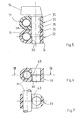
- the actuating screw 14 is essentially identical.
- the outer cone K of the actuating screw 14 is provided with at least two clamping slots 39, which are intended to facilitate narrowing of the cylindrical holding opening 30 with the reveal L when the actuating screw 14 is tightened.
- the upper clamping leg 23 or 40 has a conical opening K i (inner cone) correlating with the outer cone K a.
- the respective lower clamping leg 24 or 41 is provided with the internal thread 36 for receiving the external thread G.
- FIGS. 11-12 differs arise in the embodiments according to FIGS. 11-12 only to the extent that FIGS. 11 and 12 each represent a double clamp arrangement for receiving two fixation rods 11, while FIG. 10 shows only a single clamp 12 d.
- the embodiment according to FIG. 12 has undivided slotted tube regions 27.
- the embodiment according to FIG. 11, on the other hand, has slotted tube regions 27 divided longitudinally by axial slots 42, so that in this case there are two approximately shell-shaped clamping components with the clamping legs 40, 41 and the divided ones Slotted tube regions 27 result.
- the embodiment according to FIG. 13 differs from that according to FIG. 12 only in that it does not have any slots 43 for defining a slot tube region 27. Rather, the mounting component 12 f forms push-through jaw openings 13, which allow the fixation rods 11 to be locked by means of separate stud screws 45 provided, for example, with toggle or knurled heads 44.
- the bone screw 15 is clamped within the cylindrical opening 30 via the press cone arrangement K a and K. analogous to the exemplary embodiment according to FIG. 12.
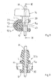
- the embodiment according to FIG. 14 with the mounting component 12 g forms a modification of the embodiment according to FIG. 12, but with the advantage of an articulated orientation and locking of the cylindrical holding opening 30 with its reveal L.
- the bracket 12 g is a bracket sided annular ball socket 46 is provided, in which a clamping ball 47 is articulated.
- a suitable plastic clamping ball 47 which consists of a suitable plastic clamping ball 47 has between a solid material bridge 48 to a radially extending lower slot 49, and a corresponding 90 0 circumferentially angularly offset radial upper slot 50th
- the clamping slots 49, 50 are intended to facilitate the deliverability in the region of the reveal surface L of the cylindrical holding opening 30. In the exemplary embodiment according to FIG. 14, this delivery takes place as follows:
- the actuating screw 14 provided with the axial cavity H has an inner cone K ii at its free end, which presses on the outside against the clamping ball 47 while the actuating screw 14 is tightened.
- the screw head of the actuating screw 14 is provided with insertion openings 60 for a plug-in tool.
- the screw axis y can also be oriented and fixed in space.
- the clamping ball 51 (FIG. 15) or clamping hemisphere 52 (FIG. 16) provided here is designed as a separate threaded part.
- the separate threaded parts 51, 52 are provided with the internal thread 36 for receiving the external thread part G of the actuating screw 14. So that the actuating screw 14 receiving the cylindrical holding opening 30 with the soffit L can be narrowed, the threaded part G has a clamping slot 39 in the axial length region of the soffit L.
- Each clamping leg 41 is provided with an annular ball socket 62 for receiving the ball 51 or the hemisphere 52.
- the washer 17 has a circular cylindrical basic shape and is rotatable in one circular cylindrical recess 53 arranged.
- the elongated hole (pivot opening) 18 is provided for the pivotability of the shaft of the screw 14.
- the spherical surface 16 accordingly forms the abutment for the underside 54 of the screw head 19.
- a combined locking is also in the sense of pre-locking both the cylindrical holding opening 30, the threaded parts 51 and 52 and the Fixator rods 11, not shown, possible within the jaw surfaces 13.
- brackets 12 j-12 m show plug-like inserts provided with contact flanges 61 for one receiving opening 55 (not shown in FIGS. 19 and 20) of an approximately plate-like or honeycomb-like bridging component 59.
- Each plug-like insert 12 j-12 m with internal thread 36 forms expansion bodies 56 with outer clamping jaw surfaces 64, which, possibly made easier by clamping slots 57, press against the wall of the receiving opening 55 when the actuating screw 14 is tightened.
- the actuating screw 14 according to FIG. 17 is provided not only with the threaded section G but also with an outer cone K a , which also has a deformation of the cylindrical holding opening 30 its reveal L causes. The same principle is followed in the embodiment according to FIG. 18.
- a roller-shaped threaded part 58 with an internal thread 36 for the external thread part G of the actuating screw 14 is provided within a circular cylindrical bearing socket 63 of the insert 12 1.
- the roller 58 has an inner cone K i , against which the outer cone K a of the actuating screw 14 strikes, causing both the elastic deformation of the clamping roller 58 and the narrowing of the cylindrical holding opening 30 and also a spreading of the expansion bodies 56.
- the holder 12 m as a separate threaded part with the internal thread 36 for the external thread G of the actuating screw 14 has a clamping hemisphere 52 which bears against the inner surface of the elastically deformable expansion body 56 forming a closed component K i can.
- the upper region of the component carrying the expansion body 56 has an elongated hole-like pivot opening 18 which is surrounded by a spherical surface 16 as an abutment for the underside 54 of the screw head 19.
- the threaded part G is also provided with a clamping slot 39 in the axial length region of the cylindrical holding opening 30.
- All plug-like embodiments according to FIGS. 17-20 have in common that the mobility of the components 58, 59 is supplemented by the rotatability of the inserts 12 1, 12 m within the cylindrical receptacle 55 of the honeycomb or plate-shaped bridging component 59 to allow room mobility.
Abstract
Description
Die Erfindung betrifft einen Fixateur externe zur Osteosynthese, wie er im Oberbegriff des Patentanspruchs 1 beschrieben und in dem Buch "Current Concepts of External Fixation of Fractures", herausgegeben von Uhthoff und Stahl, erschienen beim Springer-Verlag Berlin Heidelberg New York 1982, s. dort 99-103, vorbekannt ist.The invention relates to an external fixator for osteosynthesis, as described in the preamble of
Als wesentliche Elemente enthält der vorbekannte Fixateur zwei etwa kreiszylindrische Stahlscheiben gleichen Umfangs, welche von einer gemeinsamen Klemmschraube koaxial durchgriffen sind. In der Fuge zwischen den beiden Klemmscheiben kann gegebenenfalls eine dünne Reibscheibe vorgesehen sein. Als Klemmbacken zur Aufnahme des Überbrückungsbauteils (Fixateurstange) weist eine Klemmscheibe des Klemmscheibenpaares zwei sich sekantial und parallel zueinander erstreckende etwa zylindrische Bohrungen auf, welche die der benachbarten Klemmscheibe zugewandte radiale Kreisstirnfläche durchdringen. Es ergeben sich so zwei über einen relativ großen Umfangsbereich längsgeschlitzte Aufnahmebohrungen, in welche die Fixateurstangen - aus den Längsschlitzen einseitig längsseits vorragend - axial eingeschoben werden müssen.The known fixator contains two approximately circular cylindrical steel disks of the same circumference, which are coaxially penetrated by a common clamping screw. A thin friction disk can optionally be provided in the joint between the two clamping disks. As the clamping jaws for receiving the bridging component (fixator rod), a clamping disk of the pair of clamping disks has two approximately cylindrical bores which extend secantially and parallel to one another and penetrate the radial circular end face facing the adjacent clamping disk. This results in two receiving bores slotted longitudinally over a relatively large circumferential area, into which the fixator rods - projecting from the longitudinal slots on one side along the longitudinal side - have to be inserted axially.
Die zylindrischen Halteöffnungen zur Aufnahme entweder eines Knochennagels (z.B. eines Steinmann-Nagels) beziehungsweise einer Knochenschraube (z.B. einer Schanze'schen Schraube) sind beim vorbekannten Fixateur analog zu den beschriebenen zylindrischen Bohrungen für die Fixateurstangen ebenfalls als einseitig längsgeschlitzte zylindrische Bohrungen ausgebildet.The cylindrical holding openings for receiving either a bone nail (e.g. one Steinmann-Nagels) or a bone screw (for example a Schanze screw) are also formed in the known fixator analogous to the described cylindrical bores for the fixator rods as one-sided longitudinally slotted cylindrical bores.
Eine Verklemmung einer Fixateurstange und einer Knochenschraube geschieht bei dem vorbekannten Fixateur externe demnach gemeinsam durch Anzug der zentralen Klemmschraube derart, daß beide Klemmscheiben mit ihren zugewandten Kreisstirnflächen axial gegeneinandergepreßt werden und hierbei die aus den Längsschlitzen der Aufnahmebohrungen vorstehenden Umfangsbereiche von Fixateurstange und Knochenschraube zwischen sich verklemmen.A jamming of a fixator rod and a bone screw occurs in the known external fixator accordingly by tightening the central clamping screw in such a way that both clamping disks with their facing circular end faces are pressed axially against each other and thereby clamp the circumferential regions of the fixator rod and bone screw protruding from the longitudinal slots of the receiving bores between them.
Der durch das Buch "Current Concepts of External Fixation of Fractures" vorbekannte Fixateur externe bietet im Unterschied zu anderen durch offenkundige Vorbenutzung vorbekannten Fixateuren bereits den Vorteil einer nur wenige Bauteile umfassenden einfachen Bauform, ist jedoch hinsichtlich seiner Handhabung während der Operation und der nachherigen Versorgung des Patienten verbesserungsbedürftig.The fixator external, which is known from the book "Current Concepts of External Fixation of Fractures", offers the advantage of a simple design comprising only a few components, as opposed to other fixators who are known from prior use, but is regarding its handling during the operation and the subsequent supply of the Patients in need of improvement.
Ausgehend von dem aaO in dem Buch "Current Concepts of External Fixation of Fractures" beschriebenen Fixateur externe, liegt der Erfindung die Aufgabe zugrunde, den vorbekannten Fixateur externe unter Beibehaltung seiner vorteilhaften einfachen Bauform handhabungstechnisch zu verbessern. Diese Aufgabe wird entsprechend dem Kennzeichenteil des Anspruchs 1 gelöst.The invention lies on the basis of the external fixator described in the book "Current Concepts of External Fixation of Fractures" the task of improving the known external fixator in terms of handling while maintaining its advantageous simple design. This object is achieved in accordance with the characterizing part of
Im Unterschied zum vorbezeichneten bekannten Fixateur externe (s. "Current Concepts ..."), ist jede zylindrische Halteöffnung von einer einteiligen zusammenhängenden Laibungsfläche gebildet, welche durch Betätigung eines Schraubelements elastisch oder plastisch mit einem derartigen Ausmaß verformbar ist, daß die zylindrische Halteöffnung zunächst führend als Bohr- oder Schraublehre und - nach fortschreitender Zustellung bzw. Verengung - als Klemmaufnahme für den Knochennagel bzw. für die Knochenschraube dient. Entsprechend der Erfindung ist es grundsätzlich möglich, die zylindrischen Halteöffnungen gesondert oder - analog zum vorbekannten Fixateur - gemeinsam mit benachbarten Klemmbackenflächen, die der Aufnahme des Überbrückungsbauteils (insbesondere Fixateurstange) dienen, zuzustellen.In contrast to the known known external fixator (see "Current Concepts ..."), each cylindrical holding opening is formed by a one-piece connected reveal surface, which can be deformed elastically or plastically to such an extent by actuating a screw element that the cylindrical holding opening initially leading as a drilling or screwing gauge and - after progressive infeed or narrowing - as a clamping receptacle for the bone nail or for the bone screw. In accordance with the invention, it is fundamentally possible to feed the cylindrical holding openings separately or, analogously to the previously known fixator, together with adjacent clamping jaw surfaces which serve to accommodate the bridging component (in particular fixator rod).
Demnach kann die erste Möglichkeit einer solchen Alternative entsprechend der Erfindung darin bestehen, daß die zylindrischen Halteöffnungen bei Anzug der Betätigungsschrauben durch elastische oder plastische Werkstoffverformung bezüglich des Überbrückungsbauteils zunächst im Sinne einer Vorarretierung zustellbar und jeweils mit einem zusätzlichen Zustellhub von einer Bohrer- bzw. Schraubenführung bis zu ihrer Verklemmungs-Endlage mit dem Knochennagel bzw. mit der Knochenschraube verformbar sind.Accordingly, the first possibility of such an alternative according to the invention may consist in the fact that the cylindrical holding openings, when the actuating screws are tightened by elastic or plastic material deformation with respect to the bridging component, are initially deliverable in the sense of a pre-locking and each with an additional feed stroke of one The drill or screw guide can be deformed up to its end-of-jamming position with the bone nail or with the bone screw.
In weiterer Ausgestaltung der Erfindung kann die zweite Möglichkeit einer solchen Alternative darin bestehen, daß die zylindrischen Halteöffnungen bei Anzug der Betätigungsschrauben gemeinsam mit den benachbarten halterungsseitigen Klemmbackenflächen durch elastische oder plastische Werkstoffverformung zunächst im Sinne einer Vorarretierung (bezüglich des Uberbrückungsbauteils) zustellbar sind und daß die zylindrischen Halteöffnungen jeweils mit einem auch die Klemmbackenflächen abschließend arretierenden zusätzlichen Zustellhub von einer Bohrer- bzw. Schraubenführung bis zu ihrer Verklemmungs-Endlage mit dem Knochennagel bzw. mit der Knochenschraube verformbar sind.In a further embodiment of the invention, the second possibility of such an alternative may be that the cylindrical holding openings, when the actuating screws are tightened, together with the adjacent holder-side clamping jaw surfaces by means of elastic or plastic material deformation, are initially deliverable in the sense of a pre-locking (with regard to the bridging component) and that the cylindrical ones Each of the holding openings can be deformed with an additional feed stroke that also locks the clamping jaw surfaces, from a drill or screw guide to its end-of-jamming position with the bone nail or with the bone screw.
Eine bevorzugte erfindungsgemäße Ausführungsform kann deshalb in der Praxis mit Vorteil wie folgt gehandhabt werden: eine zylindrische Halteöffnung wird - gegebenenfalls gemeinsam mit benachbarten Klemmbackenflächen - durch Teilanzug der Betätigungsschraube vorarretiert. Dies bedeutet, daß die Halterung auf dem Überbrückungsbauteil (z.B. auf einer Fixateurstange) im wesentlichen unverschieblich gehalten und die zylindrische Halteöffnung bezüglich des Überbrückungsbauteils bzw. bezüglich der sie tragenden Halterung im wesentlichen unverstellbar positioniert ist.A preferred embodiment according to the invention can therefore advantageously be handled in practice as follows: a cylindrical holding opening is pre-locked - if appropriate together with adjacent jaw surfaces - by partially tightening the actuating screw. This means that the holder on the bridging component (e.g. on a fixation rod) is held essentially immovable and the cylindrical holding opening is positioned essentially immovably with respect to the bridging component or with respect to the holder carrying it.
Durch die zylindrische Halteöffnung hindurch können sodann zum Beispiel ein Knochenbohrer (nachfolgend gegebenenfalls ein Gewindebohrer) und, nach Herausnahme des Knochen- oder Gewindebohrers, eine Knochenschraube bzw. ein Knochennagel (letztere als Implantat) eingesetzt werden. Sobald der Knochennagel bzw. die Knochenschraube durch die zylindrische Halteöffnung hindurch befestigt ist und sich in ihrer Endlage innerhalb des Knochens befindet, erfolgt die restliche Zustellung der zylindrischen Halteöffnung bis zur Verklemmung.A bone drill (hereinafter, if necessary, a tap) and, after removing the bone or tap, a bone screw or a bone nail (the latter as an implant) can then be inserted through the cylindrical holding opening. As soon as the bone nail or the bone screw is fastened through the cylindrical holding opening and is in its end position within the bone, the rest of the delivery of the cylindrical holding opening takes place until it jams.
Aus vorstehender Schilderung wird deutlich, daß der erfindungsgemäße Fixateur operationstechnisch eine wesentliche Vereinfachung gegenüber dem Bekannten darstellt.From the above description it is clear that the fixator according to the invention represents a significant simplification in operational terms compared to the known.
Entsprechend der Erfindung ist ein Fixateur externe dann besonders vorteilhaft, wenn jeweils mit einer einzigen Betätigungsschraube sowohl die zylindrische Halteöffnung (zur sukzessiven Aufnahme eines Bohrers und einer Knochenschraube oder eines Knochennagels) als auch die Klemmbackenflächen der zugeordneten Halterung, und zwar von der Vorarretierung bis zur Endlagenarretierung, bedient werden können. Zu einer Vereinfachung der Bedienung können hierbei die Betätigungsschrauben als mit manuell bedienbaren großen Handhabungsflächen versehene Knebelschrauben ausgebildet sein. Eine elastische oder plastische Verformung der zylindrischen Halteöffnung - fakultativ gemeinsam mit benachbarten Klemmbackenflächen für das Überbrückungsbaueil - läßt sich dann vorteilhaft durchführen, wenn die an der Zustellung beteiligten Bauteile aus einem geeigneten Kunststoff bestehen. Ein solcher Kunststoff kann zu einem Kunststoffspritzgußteil verarbeitet und insbesondere kohlefaser- oder glasfaserverstärkt sein. Eine Verwendung von Kunststoffen - gegebenenfalls unter Einbeziehung der Überbrückungsbauteile - schafft neben einer Vereinfachung und Verbilligung der Herstellung und einer leichten Bauweise eine erstrebenswerte Röntgenstrahlen-Transparenz, die bei den bislang gebräuchlichen Metall-Fixateuren nicht gegeben ist.According to the invention, an external fixator is particularly advantageous if both the cylindrical holding opening (for successively receiving a drill and a bone screw or a bone nail) and the jaw surfaces of the associated holder are used with a single actuating screw, from the pre-locking to the end position locking , can be operated. To simplify the operation, the actuating screws can be designed as toggle screws provided with manually operable large handling surfaces. An elastic or plastic deformation of the cylindrical holding opening - optionally together with adjacent jaw surfaces for the bridging component - can be advantageously carried out if the components involved in the delivery consist of a suitable plastic. Such a plastic can be processed into an injection molded plastic part and in particular can be reinforced with carbon fiber or glass fiber. The use of plastics - possibly including the bridging components - in addition to simplifying and reducing the cost of manufacture and a lightweight construction, creates a desirable X-ray transparency, which is not the case with the metal fixators previously used.
Weitere Vorteile entsprechend der Erfindung ergeben sich aus zusätzlichen Unteransprüchen.Further advantages according to the invention result from additional subclaims.
In den Zeichnungen sind bevorzugte Ausführungsbeispiele der Erfindung näher dargestellt, es zeigen
- Fig. 1 einen externen lateralen Klammer- oder Monofixateur, dargestellt in Verbindung mit einer an der Tibia vorzunehmenden Distanzosteosynthese;
- Fig. 2 eine Ausführungsform mit einer zweiteiligen Halterung, deren eines Bauteil der Aufnahme einer Knochenschraube und deren anderes Bauteil der Aufnahme einer Fixateurstange dient;
- Fig. 3 eine Schnittdarstellung entsprechend der mit III bezeichneten Schnittlinie in Fig. 2;
- Fig. 4 eine Schnittdarstellung entsprechend der Schnittlinie IV-IV in Fig. 3;
- Fig. 5 eine Ausführungsform, gemäß welcher zwei Fixateur-Haltestangen zusammenwirken;
- Fig. 6 eine Einzeldarstellung ohne Betätigungsschraube und ohne Fixateurstange der unteren Teilhalterung gemäß Fig. 5;
- Fig. 7 eine Schnittdarstellung entsprechend der Schnittlinie VII-VII in Fig. 6;
- Fig. 8 eine mit einer Klemmschelle versehene andere Ausführungsform, bei welcher unmittelbar über eine einzige Betätigungsschraube sowohl ein Knochennagel als auch eine Fixateurstange arretiert werden können;
- Fig. 9 eine Schnittdarstellung gemäß der Schnittlinie IX-IX in Fig. 8;
- Fig. 10 eine Einfach-Klemmschelle analog zur Darstellung in Fig. 8, bei welcher jedoch die Verklemmung der Fixateurstange mittelbar erfolgt;
- Fig. 11 eine zweigeteilte Doppelklemmschelle, etwa als Doppelanordnung der in Fig. 10 gezeigten Anordnung;
- Fig. 12 eine Anordnung analog zu Fig. 11, bei welcher jedoch beide Klemmbackenbereiche der Doppelschelle schlitzrohrförmig ausgebildet sind;
- Fig. 13 ein Ausführungsbeispiel analog zu Fig. 12, bei welchem jedoch gesondert von der Arretierung der Knochenschraube (innerhalb der Betätigungsschraube) eine selektive Arretierung der Halterung an den Fixateurstangen möglich ist;
- Fig. 14 analog zu Fig. 12 eine Doppelklemmschelle mit einer raumgelenkigen Positionierung und Arretierung einer Knochenschraube und dem Vorteil einer direkten Arretierung der beiden Fixateurstangen durch die Betätigungsschraube;
- Fig. 15 und 16 weitere Ausführungsformen analog zu der gemäß Fig. 14;
- Fig. 17-20 verschiedene stopfenartige Halterungen zum Einsatz in etwa platten- bzw. wabenförmige Überbrückungsbauteile.
- 1 shows an external lateral clamp or monofixer, shown in connection with a distance osteosynthesis to be carried out on the tibia;
- 2 shows an embodiment with a two-part holder, one component of which is used to hold a bone screw and the other component is used to hold a fixator rod;
- Fig. 3 is a sectional view corresponding to the section line labeled III in Fig. 2;
- Fig. 4 is a sectional view along the section line IV-IV in Fig. 3;
- 5 shows an embodiment according to which two fixator support rods interact;
- FIG. 6 shows an individual illustration without an actuating screw and without a fixator rod of the lower part holder according to FIG. 5;
- Fig. 7 is a sectional view along the section line VII-VII in Fig. 6;
- 8 shows another embodiment provided with a clamp, in which both a bone nail and a fixator rod can be locked directly by means of a single actuating screw;
- Fig. 9 is a sectional view along the section line IX-IX in Fig. 8;
- FIG. 10 shows a single clamp analogous to the representation in FIG. 8, in which, however, the fixation rod is clamped indirectly;
- 11 shows a two-part double clamp, approximately as a double arrangement of the arrangement shown in FIG. 10;
- FIG. 12 shows an arrangement analogous to FIG. 11, in which, however, both clamping jaw areas of the double clamp are designed in the form of a slit tube;
- FIG. 13 shows an exemplary embodiment analogous to FIG. 12, in which, however, a selective locking of the holder on the fixator rods is possible separately from the locking of the bone screw (within the actuating screw);
- 14 analogously to FIG. 12, a double clamp with a articulated positioning and locking of a bone screw and the advantage of a direct locking of the two fixation rods by the actuating screw;
- 15 and 16 further embodiments analogous to that according to FIG. 14;
- Fig. 17-20 different plug-like holders for use in approximately plate or honeycomb bridging components.
Soweit möglich, sind für gleiche oder ähnliche Teile dieselben oder ähnliche Bezugszeichen verwendet.Wherever possible, the same or similar reference numerals are used for the same or similar parts.
In Fig. 1 ist ein gesamter Fixateur externe mit der Bezugsziffer 10 bezeichnet. Der Fixateur externe ist am Beispiel einer mit T bezeichneten Tibia gezeigt, bei welcher im Frakturbereich F eine Distanzosteosynthese vorgenommen wird.In Fig. 1, an entire external fixator is designated by the
Hierzu weist der Fixateur 10 zwei Fixateurstangen 11 auf, welche in vier Halterungen 12 klemmarretiert sind. Jede Halterung 12 ist mit Klemmbackenflächen 13 zur Aufnahme der Fixateurstangen 11 versehen.For this purpose, the
Die Verklemmung der Klemmbackenflächen 13 auf den Fixateurstangen 11 wird durch Betätigungsschrauben 14 bewirkt. Durch Anzug der Betätigungsschrauben 14 werden zugleich aus Fig. 1 nicht entnehmbare zylindrische Halteöffnungen bis zur Verklemmung mit den in ihnen aufgenommenen Knochenschrauben 15 (sogenannte "Schanze'sche Schrauben") zugestellt.The jamming of the jaw surfaces 13 on the
Zur Aufnahme der Knochenschrauben 15 sind Bauteile vorgesehen, wie sie etwa in den Fig. 15 bzw. 16 gezeigt sind. Zu diesen Bauteilen gehören Unterlegscheiben 17, die der räumlichen Ausrichtung der Knochenschrauben 15 dienen. Die drehbaren Unterlegscheiben 17 sind im Bereich ihrer balligen Oberfläche 16 mit einem Langloch 18 zur Aufnahme des nicht gezeigten Schraubenschaftes der Betätigungsschraube 14 versehen, die wiederum die Knochenschraube 15 enthält.Components are provided for receiving the bone screws 15, as are shown, for example, in FIGS. 15 and 16. These components include
Die praktische Handhabung des in Fig. 1 dargestellten Fixateurs externe vollzieht sich etwa wie folgt:The practical handling of the external fixator shown in FIG. 1 takes place approximately as follows:
Die Relativlage der Halterungen 12 auf den Überbrückungsbauteilen (Fixateurstangen 11) wird durch teilweisen Anzug der betreffenden Betätigungsschraube 14 mit deren Handbetätigungsknebel 19 bewirkt. Durch diesen Teilanzug wird außerdem die Längsachse y jeder Betätigungsschraube in einer gewünschten räumlichen Lage vorarretiert.The relative position of the
Durch die stirnseitige Öffnung 20 (die in die nicht gezeigte zylindrische Halteöffnung übergeht) der betreffenden Betätigungsschraube 14 wird sodann in nicht gezeigter Weise ein Knochenbohrer axial hindurchgeführt und die Haltebohrung B in die Tibia eingebracht. Nach Herausnahme des Knochenbohrers wird sodann durch die Öffnung 20 der Betätigungsschraube 14 hindurch ein Gewindebohrer eingesetzt und die Knochenbohrung B mit einem Innengewinde versehen. Nach Herausdrehen des Knochen-Gewindebohrers wird sodann durch die Öffnung 20 der Betätigungsschraube 14 hindurch die Knochenschraube 15 eingesetzt. Nachdem die Knochenschraube 15 ihre endgültige Befestigungslage in der Knochenbohrung B erreicht hat, wird die betreffende Betätigungsschraube 14 mittels des Betätigungsknebels 19 manuell zugrundegezogen. Hierdurch werden sowohl die Halterung 12 auf der zugeordneten Fixateurstange 11 als auch die Knochenschraube 15 innerhalb der Betätigungsschraube 14 und auch schließlich das Raumgelenksystem (von dem nur die Unterlegscheibe 17 in Fig. 1 gezeigt ist) relativ zur Fixateurstange 11 fest klemmarretiert.A bone drill is then axially passed through the front opening 20 (which merges into the cylindrical holding opening, not shown) of the
Anhand der Darstellung gemäß Fig. 1 ist ohne weiteres vorstellbar, daß die dort gezeigten Bauelemente auch zur Erstellung eines Rahmenfixateurs oder eines Fixateurs nach Art eines Raumfachwerks verwendet werden können. Hierbei würden nicht dargestellte zusätzliche Halterungen 12 einseitig an den beiden Fixateurstangen 11 angeklemmt sein und als Kupplungsglieder zu weiteren nicht dargestellten seitlich benachbarten Fixateurstangen 11 dienen. Auf diese Weise können auch zur Halterung von Steinmann-Nägeln Halterungen 12 (mit Betätigungsschrauben 14) an einander diametral gegenüberliegenden Seiten der Tibia T angeordnet werden. Die Verwendung des Fixateurs 10 ist selbstverständlich nicht auf eine Tibia T beschränkt sondern vorteilhaft auch bei anderen Extremitäten sowie des Beckens, gegebenenfalls auch gelenkübergreifend, möglich.On the basis of the representation according to FIG. 1, it is readily conceivable that the components shown there can also be used to create a frame fixator or a fixator in the manner of a spatial framework. Here,
Beim Ausführungsbeispiel gemäß den Fig. 2-4 weist die zweiteilige Halterung 12 a zwei Klemmschellen 21, 22 auf.In the embodiment according to FIGS. 2-4, the two-part holder 12 a has two
Jede Klemmschelle 21, 22 besitzt je zwei einander parallele Klemmschenkel 23, 24 sowie 25, 26. Jeweils zwei Klemmschenkel 23, 24 bzw. 25, 26 sind durch einen Schlitzrohrbereich 27, 28 miteinander verbunden.Each
Der Schlitzrohrbereich 27 der Klemmschelle 22 bildet die Klemmbackenfläche 13 für die aus kohlefaserverstärktem Kunststoff bestehende Fixateurstange 11. Für den Fall, daß Fixateurstangen 11 mit Durchmessertoleranzen verwendet werden, kann zum Ausgleich eines Fixateurstangen-Untermaßes eine Schlitzhülse 29 in die Klemmbackenfläche 13 eingeschoben werden. Die Schlitzhülse 29 bildet demnach eine umfangsveränderliche Paßbuchse.The
-Die andere Klemmschelle 21 enthält die zylindrische Halteöffnung 30 zur Aufnahme der Knochenschraube 15.The
Eine Besonderheit bei beiden Klemmschellen 21 und 22 besteht darin, daß die jeweils nur einen Schlitzrohrbereich 27 bzw. 28 aufweisenden Klemmschellen 21 und 22 endseitig ihrer beiden Klemmschenkel 23, 24; 25, 26 über je eine Werkstoffbrücke 31, 32 einstückig-stoffschlüssig miteinander verbunden sind. Die Werkstoffbrücken 31, 32 dienen der Erzielung definierter Klemmverhältnisse.A special feature of both
Von den vier aufeinanderfolgenden Klemmschenkeln 25, 26, 23, 24 weisen drei Klemmschenkel 25, 26, 23 je eine glatte Durchgangsbohrung 33, 34, 35 und der eine Klemmschenkel 24 eine Innengewindebohrung 36 für das Gewindeteil 37 der gemeinsamen Betätigungsschraube 14 auf, welche bei der Ausführungsform gemäß den Fig. 2-4 die zylindrische Halteöffnung 30 selbst nicht bildet.Of the four
Bei der Ausführungsform gemäß den Fig. 2-4 werden sowohl die Klemmbackenfläche 13 als auch die zylindrische Haltebohrung 30 gemeinsam über die Betätigungsschraube 14 bedient. Wie bereits im Zusammenhang mit Fig. 1 dargelegt, ist hierbei eine Vorarretierung der Halterung 12 a bezüglich der Fixateurstange 11 und der Knochenschraube 15 bzw. bezüglich eines nicht dargestellten Bohrers möglich. Erst ein weiteres Zugrundeziehen der Betätigungsschraube 14 bewirkt eine gemeinsame feste Endlagenverklemmung der Fixateurstange 11 bezüglich der Klemmbackenfläche 13 bzw. bezüglich der Schlitzhülse 29 und der Knochenschraube 15 bezüglich der zylindrischen Halteöffnung 30.In the embodiment according to FIGS. 2-4, both the
Zur Sicherung der relativen Drehlage der Klemmschellen 21, 22 zueinander ist an den einander zugewandten Berührungsflächen je eine Plan-KerbVerzahnung, sogenannte "Hirth-Verzahnung", welche die Bezugsziffer 38 trägt, vorgesehen.To secure the relative rotational position of the
Bei der Ausführungsform gemäß den Fig. 5-7 sind zwei im wesentlichen gleiche Klemmschellen 22, 22 vorgesehen, von denen jedoch die obere zwei glatte Durchgangsbohrungen 35 aufweist, während die untere Klemmschelle 21 eine glatte Durchgangsbohrung 35 und eine Innengewindebohrung 36 besitzt. Die Verklemmung der beiden je eine rohrförmige Fixateurstange 11 aufnehmenden Klemmschellen 22, 22 geschieht analog zum Ausführungsbeispiel gemäß den Fig. 2-4. Eine zylindrische Halteöffnung 30 ist bei der Ausführungsform gemäß den Fig. 5-7 nicht gezeigt, jedoch ist es ohne weiteres denkbar, daß die Betätigungsschraube 14 eine zylindrische Halteöffnung 30, etwa analog zur Betätigungsschraube 14 gemäß Fig. 8, enthält.In the embodiment according to FIGS. 5-7, two essentially
Bei der Ausführungsform gemäß den Fig. 8 und 9 ist die Betätigungsschraube 14 von einem Axialhohlraum H durchsetzt, welcher die Laibungsfläche L zur Bildung der zylindrischen Halteöffnung 30 enthält. Oberhalb des Außengewindeabschnittes G der Betätigungsschraube 14 weist diese einen Außenkonus K a auf. Dieser Außenkonus K a ist etwa in axialer Höhe der zylindrischen Halteöffnung 30 angeordnet. Wenn nun die Betätigungsschraube 14 angezogen wird, legt sich der Außenkonus K zunehmend an die Außenfläche der Fixateurstange 11 an, wodurch einerseits die Außenfläche der Fixateurstange 11 gegen die Klemmbackenfläche 13 des Schlitzrohrbereichs 27 gezogen wird. Andererseits wird der Außenkonus K selbst - und damit die a Laibungsfläche L im Sinne einer Verengung - elastisch deformiert. Hierbei bleibt anzumerken, daß die Bauteile 14 sowie die Klemmschellenhalterung 12 b (ebenso wie analoge Bauteile der voraufgegangenen und nachstehend gezeigten Figuren) aus einem entropieelastisch verformbaren Kunststoff, und zwar als Spritzgußteile, hergestellt sind. Vorzuziehen ist ein Kunststoff unter Verwendung von Faserteilen, insbesondere von Kohlenstoff-oder Glasfasern.In the embodiment according to FIGS. 8 and 9, the
Bei den Ausführungsformen gemäß den Fig. 10-13 mit den Halterungen 12 c, 12 d, 12 e und 12 f ist die Betätigungsschraube 14 im wesentlichen identisch ausgebildet. Und zwar ist der Außenkonus K der Betätigungsschraube 14 mit mindestens zwei Klemmschlitzen 39 versehen, welche eine Verengung der zylindrischen Halteöffnung 30 mit der Laibung L beim Anzug der Betätigungsschraube 14 erleichtern sollen. Als Widerlagerfläche bzw. Anschlag für den Außenkonus K weist jeweils der obere Klemmschenkel 23 bzw. 40 eine dem Außenkonus K a korrelierende konische Öffnung Ki (Innenkonus) auf. Der jeweils untere Klemmschenkel 24 bzw. 41 hingegen ist zur Aufnahme des Außengewindes G mit dem Innengewinde 36 versehen. Hierdurch können die Klemmschenkel 23, 24; 40, 41 (mit ihnen die Klemmbackenflächen 13) zugleich mit den zylindrischen Halteöffnungen zugestellt werden.In the embodiments according to FIGS. 10-13 with the brackets 12 c, 12 d, 12 e and 12 f, the
Unterschiede ergeben sich bei den Ausführungsformen gemäß den Fig. 11-12 nur insoweit, als die Fig. 11 und 12 jeweils eine Doppelschellenanordnung zur Aufnahme von zwei Fixateurstangen 11 darstellen, während Fig. 10 nur eine Einfachschelle 12 d zeigt. Die Ausführungsform gemäß Fig. 12 besitzt ungeteilte Schlitzrohrbereiche 27. Die Ausführungsform gemäß Fig. 11 weist hingegen durch Axialschlitze 42 längsgeteilte Schlitzrohrbereiche 27 auf, so daß sich in diesem Falle zwei etwa schalenförmige Klemmbauteile mit den Klemmschenkeln 40, 41 und den geteilten Schlitzrohrbereichen 27 ergeben.Differences arise in the embodiments according to FIGS. 11-12 only to the extent that FIGS. 11 and 12 each represent a double clamp arrangement for receiving two
Beim Ausführungsbeispiel gemäß Fig. 10 ist als Halterung nur die Einfachschelle 12 d mit einem ungeteilten Schlitzrohrbereich 27 und einer durchgehenden Werkstoffbrücke 31 zwischen den beiden Klemmschenkeln 23, 24 vorgesehen.In the exemplary embodiment according to FIG. 10, only the single clamp 12 d with an undivided slotted
Die Ausführungsform gemäß Fig. 13 unterscheidet sich von der gemäß Fig. 12 nur dadurch, daß diese keine Schlitze 43 zur Definition eines Schlitzrohrbereiches 27 aufweist. Vielmehr bildet das Halterungsbauteil 12 f Durchsteck-Klemmbacken- öffnungen 13, welche eine Arretierung der Fixateurstangen 11 über beispielsweise mit Knebel-oder Rändelköpfen 44 versehene gesonderte Stiftschrauben 45 gestatten. Die Verklemmung der Knochenschraube 15 innerhalb der zylindrischen Öffnung 30 geschieht über die Preß-Konenanordnung Ka und K. analog zum Ausführungsbeispiel gemäß Fig. 12.The embodiment according to FIG. 13 differs from that according to FIG. 12 only in that it does not have any
Die Ausführungsform gemäß Fig. 14 mit dem Halterungsbauteil 12 g bildet eine Abwandlung der Ausführungsform gemäß Fig. 12, jedoch mit dem Vorteil einer raumgelenkigen Orientierung und Arretierung der zylindrischen Halteöffnung 30 mit ihrer Laibung L. Zugleich wird der Vorteil einer direkten Verklemmung der beiden Fixateurstangen 11 durch die Betätigungsschraube 14 erzielt. Und zwar ist bei der Halterung 12 g eine halterungsseitige kreisringartige Kugelpfanne 46 vorgesehen, in welcher eine Klemmkugel 47 raumgelenkig gelagert ist. Die aus einem geeigneten Kunststoff bestehende Klemmkugel 47 weist zwischen einer festen Werkstoffbrücke 48 einen radial verlaufenden unteren Schlitz 49 und einen hierzu um 900 umfangswinkelversetzten radialen oberen Schlitz 50 auf. Die Klemmschlitze 49, 50 sollen die Zustellbarkeit im Bereich der Laibungsfläche L der zylindrischen Halteöffnung 30 erleichtern. Diese Zustellung erfolgt beim Ausführungsbeispiel gemäß Fig. 14 wie folgt:The embodiment according to FIG. 14 with the mounting
Die mit dem Axialhohlraum H versehene Betätigungsschraube 14 weist an ihrem freien Ende einen Innenkonus Kii auf, welcher außen gegen die Klemmkugel 47 drückt, während die Betätigungsschraube 14 angezogen wird. Am freien Ende des Außengewindes G der Betätigungsschraube 14 befindet sich wiederum ein Außenkonus K , welcher wiederum a gegen die Außenfläche der Fixateurstangen 11 drückt. Auf diese Weise können beim Ausführungsbeispiel gemäß Fig. 14 - auch im Sinne einer Vorarretierung - eine Richtungsfixierung der Achse y, eine Verklemmung der Knochenschraube 15 innerhalb der zylindrischen Halteöffnung 30 als auch eine Arretierung der Fixateurstangen 11 innerhalb der Klemmbackenflächen 13 erfolgen.The
Der Schraubenkopf der Betätigungsschraube 14 ist mit Einstecköffnungen 60 für ein Steckwerkzeug versehen.The screw head of the
In den Fig. 15 und 16 sind die miteinander baulich verwandten Halterungen 12h und 12i dargestellt.15 and 16, the structurally
Auch bei den Ausführungsformen gemäß den Fig. 15 und 16 ist die Schraubenachse y raumgelenkig orientier- und fixierbar. Die hier vorgesehene Klemmkugel 51 (Fig. 15) bzw. Klemmhalbkugel 52 (Fig. 16) ist als ein gesondertes Gewindeteil ausgebildet. Die gesonderten Gewindeteile 51, 52 sind mit dem Innengewinde 36 zur Aufnahme des Außengewindeteils G der Betätigungsschraube 14 versehen. Damit eine Verengung der die zylindrische Halteöffnung 30 mit der Laibung L aufnehmenden Betätigungsschraube 14 erfolgen kann, weist das Gewindeteil G im axialen Längenbereich der Laibung L jeweils einen Klemmschlitz 39 auf. Für den Fall, daß größere Klemmkräfte aufgebracht werden müssen ist es zweckmäßig, die Kugel 51 vorzusehen, während für geringere Klemmkräfte (geringe axiale Länge des Gewindes 36) eine Halbkugel 52 genügt.In the embodiments according to FIGS. 15 and 16, the screw axis y can also be oriented and fixed in space. The clamping ball 51 (FIG. 15) or clamping hemisphere 52 (FIG. 16) provided here is designed as a separate threaded part. The separate threaded
Zur Aufnahme von der Kugel 51 bzw. der Halbkugel 52 ist jeder Klemmschenkel 41 mit einer ringförmigen Kugelpfanne 62 versehen.Each clamping
In den Fig. 15 und 16 ist auch die bereits im Zusammenhang mit Fig. 1 erwähnte Unterlegscheibe 17 mit ihrer balligen Oberfläche 16 näher dargestellt. Die Unterlegscheibe 17 besitzt eine kreiszylindrische Grundform und ist drehbar in einer kreiszylindrischen Ausnehmung 53 angeordnet. Zur Schwenkbarkeit des Schaftes der Schraube 14 ist das Langloch (Schwenköffnung) 18 vorgesehen. Die ballige Oberfläche 16 bildet demnach das Widerlager für die Unterseite 54 des Schraubkopfes 19. Auch bei den Ausführungsformen gemäß den Fig. 15 und 16 ist eine kombinierte Arretierung auch im Sinne einer Vorarretierung sowohl der zylindrischen Halteöffnung 30, des Gewindeteile 51 bzw. 52 und der nicht dargestellten Fixateurstangen 11 innerhalb der Klemmbackenflächen 13 möglich.15 and 16 also shows the
Fig. 17-20 mit den Halterungen 12 j-12 m zeigen mit Anlageflanschen 61 versehene stopfenartige Einsätze für je eine Aufnahmeöffnung 55 (in den Fig. 19 und 20 nicht dargestellt) eines etwa platten- bzw. wabenartigen Überbrückungsbauteils 59 aus. für Röntgenstrahlen transparentem geeigneten Kunststoff.17-20 with the
Jeder stopfenartige Einsatz 12 j-12 m mit Innengewinde 36 bildet Spreizkörper 56 mit äußeren Klemmbackenflächen 64, welche sich, gegebenenfalls erleichtert durch Klemmschlitze 57, beim Anzug der Betätigungsschraube 14 gegen die Wandung der Aufnahmeöffnung 55 andrücken. Hierzu ist die Betätigungsschraube 14 gemäß Fig. 17 außer mit dem Gewindeabschnitt G auch mit einem Außenkonus K a versehen, welcher zudem eine Deformation der zylindrischen Halteöffnung 30 mit ihrer Laibung L bewirkt. Das gleiche Prinzip wird beim Ausführungsbeispiel gemäß Fig. 18 verfolgt.Each plug-
Gemäß Fig. 19 ist ein walzenförmiges Gewindeteil 58 mit einem Innengewinde 36 für das Außengewindeteil G der Betätigungsschraube 14 inner-' halb einer kreiszylindrischen Lagerpfanne 63 des Einsatzes 12 1 vorgesehen. Zusätzlich weist die Walze 58 einen Innenkonus Ki auf, gegen den der Außenkonus K a der Betätigungsschraube 14, sowohl die elastische Deformation der Klemmwalze 58 als auch die Verengung der zylindrischen Halteöffnung 30 sowie auch eine Spreizung der Spreizkörper 56 bewirkend, anschlägt.19, a roller-shaped threaded
Beim Ausführungsbeispiel gemäß Fig. 20 weist die Halterung 12 m als gesondertes Gewindeteil mit dem Innengewinde 36 für das Außengewinde G der Betätigungsschraube 14 eine Klemmhalbkugel 52 auf, welche sich gegen die einen Innenkonus Ki bildende Innenfläche des ein geschlossenes Bauteil bildenden elastisch deformierbaren Spreizkörpers 56 anlegen kann. Analog zu den Ausführungsformen der Fig. 15 und 16 weist der obere Bereich des den Spreizkörper 56 tragenden Bauteils eine langlochartige Schwenköffnung 18 auf, die von einer balligen Oberfläche 16 als Widerlager für die Unterseite 54 des Schraubkopfes 19 umgeben ist. Auch das Gewindeteil G ist im axialen Längenbereich der zylindrischen Halteöffnung 30 mit einem Klemmschlitz 39 versehen.In the exemplary embodiment according to FIG. 20, the holder 12 m as a separate threaded part with the
Allen stopfenartigen Ausführungsformen gemäß den Fig. 17-20 ist gemeinsam, daß die Beweglichkeit der Bauteile 58, 59 durch die Drehbarkeit der Einsätze 12 1, 12 m innerhalb der zylindrischen Aufnahme 55 des waben- bzw. plattenförmigen Überbrückungsbauteils 59 zu einer Raumbeweglichkeit ergänzt wird.All plug-like embodiments according to FIGS. 17-20 have in common that the mobility of the
Claims (28)
Priority Applications (1)
| Application Number | Priority Date | Filing Date | Title |
|---|---|---|---|
| AT87105092T ATE71502T1 (en) | 1986-04-04 | 1987-04-06 | EXTERNAL FIXATEUR FOR OSTEOSYNTHESIS. |
Applications Claiming Priority (2)
| Application Number | Priority Date | Filing Date | Title |
|---|---|---|---|
| DE3611319 | 1986-04-04 | ||
| DE19863611319 DE3611319A1 (en) | 1986-04-04 | 1986-04-04 | FIXATEUR EXTERNAL ON OSTEOSYNTHESIS |
Publications (2)
| Publication Number | Publication Date |
|---|---|
| EP0240034A1 true EP0240034A1 (en) | 1987-10-07 |
| EP0240034B1 EP0240034B1 (en) | 1992-01-15 |
Family
ID=6297929
Family Applications (1)
| Application Number | Title | Priority Date | Filing Date |
|---|---|---|---|
| EP87105092A Expired - Lifetime EP0240034B1 (en) | 1986-04-04 | 1987-04-06 | External fixation for osteosynthesis |
Country Status (8)
| Country | Link |
|---|---|
| US (1) | US4920959A (en) |
| EP (1) | EP0240034B1 (en) |
| AT (1) | ATE71502T1 (en) |
| CA (1) | CA1318820C (en) |
| DE (2) | DE3611319A1 (en) |
| ES (1) | ES2030008T3 (en) |
| GR (1) | GR3003590T3 (en) |
| WO (1) | WO1993012729A1 (en) |
Cited By (11)
| Publication number | Priority date | Publication date | Assignee | Title |
|---|---|---|---|---|
| WO1990012547A1 (en) * | 1989-04-18 | 1990-11-01 | Betz, Augustin | Fixation system for tubular bone fractures |
| EP0408489A1 (en) * | 1989-07-12 | 1991-01-16 | SULZER Medizinaltechnik AG | Implant for the fixation of two vertebrae |
| EP0517939A1 (en) * | 1991-06-12 | 1992-12-16 | Fehling Mediprodukt Gmbh | Medical fixation device |
| FR2688685A1 (en) * | 1992-03-19 | 1993-09-24 | Loniewski Xavier | LINEAR ORTHOPEDIC EXTERNAL FIXATION APPARATUS. |
| WO1993022984A1 (en) * | 1992-05-15 | 1993-11-25 | Deszczyn & Cir & Ski Jaroslaw | A stabilizer for treating broken bones |
| EP0596788A1 (en) * | 1992-11-06 | 1994-05-11 | BIOMAT(S.a.r.l.) | Osteosynthesis device for spinal consolidation |
| FR2701833A1 (en) * | 1993-02-24 | 1994-09-02 | Garin Christophe | Fixator for lumbosacral osteosynthesis |
| US5474553A (en) * | 1989-04-18 | 1995-12-12 | Rainer Baumgart | System for setting tubular bone fractures |
| US6149653A (en) * | 1997-09-05 | 2000-11-21 | Deslauriers; Richard J. | Self-retaining anchor track and method of making and using same |
| EP2774560A3 (en) * | 2013-03-06 | 2014-11-12 | Stryker Trauma SA | Mini-rail external fixator |
| US10531896B2 (en) | 2015-08-10 | 2020-01-14 | Stryker European Holdings I, Llc | Distraction tube with wire clamp |
Families Citing this family (71)
| Publication number | Priority date | Publication date | Assignee | Title |
|---|---|---|---|---|
| DE3807335A1 (en) * | 1988-03-05 | 1989-09-14 | Orthoplant Endoprothetik | Repositioning and distraction apparatus |
| DE8805407U1 (en) * | 1988-04-23 | 1988-06-09 | Herzberg, Wolfgang, Dr. Med., 2000 Wedel, De | |
| CH683963A5 (en) * | 1988-06-10 | 1994-06-30 | Synthes Ag | Internal fixation. |
| IT1228812B (en) * | 1989-03-22 | 1991-07-04 | Ortomedical S R L | EXTRAFOCAL FIXING EQUIPMENT FOR TRANSOXIC SYNTHESIS OF DISTRACTIONS AND COMPRESSIONS IN ORTHOPEDICS AND TRAUMATOLOGY. |
| US5219349A (en) * | 1991-02-15 | 1993-06-15 | Howmedica, Inc. | Spinal fixator reduction frame |
| US5080661A (en) * | 1991-04-18 | 1992-01-14 | Hollister Incorporated | Fixation pin entry site dressing and method |
| US5318575A (en) * | 1992-02-03 | 1994-06-07 | United States Surgical Corporation | Method of using a surgical repair suture product |
| JP3382643B2 (en) * | 1992-09-28 | 2003-03-04 | 長野計器株式会社 | Surgery template device with screw pin |
| US5355913A (en) * | 1992-10-09 | 1994-10-18 | United States Surgical Corporation | Surgical repair device |
| US5417698A (en) * | 1992-10-09 | 1995-05-23 | United States Surgical Corporation | Apparatus for tightening elongated wound closure elements |
| US5356412A (en) * | 1992-10-09 | 1994-10-18 | United States Surgical Corporation | Sternum buckle with rotational engagement and method of closure |
| US5330489A (en) * | 1992-10-09 | 1994-07-19 | United States Surgical Corporation | Sternum closure buckle |
| US5306275A (en) * | 1992-12-31 | 1994-04-26 | Bryan Donald W | Lumbar spine fixation apparatus and method |
| US5498262A (en) * | 1992-12-31 | 1996-03-12 | Bryan; Donald W. | Spinal fixation apparatus and method |
| US5947965A (en) | 1992-12-31 | 1999-09-07 | Bryan; Donald W. | Spinal fixation apparatus and method |
| US5785709A (en) * | 1993-05-10 | 1998-07-28 | Hospital For Joint Diseases Orthopaedic Institute | Apparatus and method for performing a surgical procedure on bone lesions |
| US5496319A (en) * | 1994-06-27 | 1996-03-05 | Zimmer, Inc. | External fixation apparatus |
| GB9419408D0 (en) * | 1994-09-27 | 1994-11-09 | Newson Charles J | A bone fixing screw pin |
| FR2725613B1 (en) * | 1994-10-12 | 1997-03-14 | Hardy Jean Marie | EXTERNAL FIXER APPLICABLE IN ORTHOPEDICS AND TRAUMATOLOGY |
| US5620443A (en) | 1995-01-25 | 1997-04-15 | Danek Medical, Inc. | Anterior screw-rod connector |
| US5562661A (en) * | 1995-03-16 | 1996-10-08 | Alphatec Manufacturing Incorporated | Top tightening bone fixation apparatus |
| US5662650A (en) * | 1995-05-12 | 1997-09-02 | Electro-Biology, Inc. | Method and apparatus for external fixation of large bones |
| IT1293941B1 (en) * | 1997-02-13 | 1999-03-11 | Orthofix Srl | ORTHOPEDIC TOOL PARTICULARLY FOR THE SURGICAL CORRECTION OF BONE DEFORMATIONS |
| FR2761256B1 (en) | 1997-04-01 | 1999-06-11 | Daniel Chopin | RACHIDIAN OSTEOSYNTHESIS INSTRUMENTATION WITH CONNECTING CONNECTOR BETWEEN A VERTEBRAL ROD AND BONE ANCHORING ORGANS |
| US6413258B1 (en) | 1999-08-12 | 2002-07-02 | Osteotech, Inc. | Rod-to-rod coupler |
| AU755182B2 (en) * | 1999-11-15 | 2002-12-05 | Ao Technology Ag | Method and device for the determination of reduction parameters for the subsequent reduction of a fractured bone |
| KR20020005339A (en) * | 2000-07-06 | 2002-01-17 | 박찬협 | Anatomy conguest and maintenance of bone fracture |
| US7722645B2 (en) * | 2001-09-24 | 2010-05-25 | Bryan Donald W | Pedicle screw spinal fixation device |
| FR2835174B1 (en) * | 2002-01-31 | 2004-03-19 | Materiel Orthopedique En Abreg | CONNECTOR FOR SPINAL OSTEOSYNTHESIS DEVICE, BONE ANCHOR CONNECTOR / MEMBER ASSEMBLY AND SPINAL OSTEOSYNTHESIS DEVICE USING THE SAME |
| WO2005002450A2 (en) * | 2003-06-30 | 2005-01-13 | Oguzhan Koroglu | Process for producing an external fixation device, particularly an ilizarov fixator |
| ATE428361T1 (en) | 2003-07-29 | 2009-05-15 | Synthes Gmbh | DEVICE FOR FIXING A LONGITUDINAL SUPPORT WITH A BONE FIXATION ELEMENT |
| BRPI0418627B1 (en) * | 2004-03-10 | 2017-03-07 | Synthes Gmbh | device for mutual positioning of longitudinal building components |
| CA2559497C (en) | 2004-03-10 | 2013-05-14 | Synthes (U.S.A.) | External fixer for osteosynthesis |
| US8236028B2 (en) * | 2004-03-31 | 2012-08-07 | Depuy Spine Sarl | Spinal rod connector |
| WO2005099788A1 (en) * | 2004-04-19 | 2005-10-27 | Synthes Gmbh | Elastic element produced from radiolucent material for a medical device |
| US20060155276A1 (en) * | 2005-01-11 | 2006-07-13 | Walulik Stephen B | Bone fixation assembly and related method |
| ES2302173T3 (en) | 2005-01-18 | 2008-07-01 | Synthes Gmbh | DEVICE WITH ANGULAR STABILITY FOR THE MUTUAL FIXATION OF A LONGITUDINAL SUPPORT TO AN ELEMENT TO FIX BONES. |
| US20060235383A1 (en) * | 2005-03-07 | 2006-10-19 | Shane Hollawell | External fixator |
| US20060229605A1 (en) * | 2005-03-18 | 2006-10-12 | Olsen Ron A | Adjustable splint for osteosynthesis with incrementing assembly for adjustment in predetermined increments |
| US7507240B2 (en) * | 2005-03-18 | 2009-03-24 | Ron Anthon Olsen | Adjustable splint for osteosynthesis |
| DE202005005444U1 (en) | 2005-04-01 | 2005-06-02 | Tantum Ag | Particularly stable bone fixing device, assembled of two central elements and two fixing rods holding devices |
| US8758343B2 (en) | 2005-04-27 | 2014-06-24 | DePuy Synthes Products, LLC | Bone fixation apparatus |
| US7803174B2 (en) * | 2005-11-04 | 2010-09-28 | Warsaw Orthopedic, Inc. | Dorsal adjusting multi-rod connector |
| US7731738B2 (en) | 2005-12-09 | 2010-06-08 | Orthopro, Llc | Cannulated screw |
| US8114080B2 (en) * | 2006-09-27 | 2012-02-14 | Depuy Products, Inc. | Flexible bone fixation device |
| US8277448B2 (en) * | 2007-03-07 | 2012-10-02 | Wright Medical Technology, Inc. | External fixation |
| US8419733B2 (en) * | 2007-08-16 | 2013-04-16 | Nutek Orthopedics, Inc. | External fixation apparatus with adjustable pin clamping means |
| JP5463574B2 (en) * | 2007-09-27 | 2014-04-09 | ジンマー,インコーポレイティド | External fixation and stabilization method and clamping device |
| CN102626338B (en) | 2008-01-14 | 2014-11-26 | 康文图斯整形外科公司 | Apparatus and methods for fracture repair |
| US8323292B2 (en) * | 2008-12-15 | 2012-12-04 | Spinecore, Inc. | Adjustable pin drill guide and methods therefor |
| US8657856B2 (en) * | 2009-08-28 | 2014-02-25 | Pioneer Surgical Technology, Inc. | Size transition spinal rod |
| FR2954905B1 (en) * | 2010-01-06 | 2012-12-28 | Implanet | DEVICE FOR FIXING VERTEBRAL |
| WO2012122317A2 (en) * | 2011-03-07 | 2012-09-13 | Conventus Orthopaedics, Inc. | Apparatus and methods for bone repair preparation |
| US9247997B2 (en) * | 2011-09-30 | 2016-02-02 | Ethicon Endo-Surgery, Inc. | Patient-referenced surgical support frame |
| US9301783B2 (en) | 2013-01-23 | 2016-04-05 | Fixx Orthopedics, LLC | Orthopedic external fixation device |
| US20140257418A1 (en) * | 2013-03-07 | 2014-09-11 | Kyphon Sarl | Surgical tool holder |
| EP2967670B1 (en) * | 2013-03-15 | 2023-06-28 | Biomet C.V. | Clamping assembly for external fixation system |
| US9408635B2 (en) | 2013-03-15 | 2016-08-09 | Wright Medical Technology, Inc. | External fixation |
| US9962188B2 (en) | 2013-10-29 | 2018-05-08 | Cardinal Health 247. Inc. | External fixation system and methods of use |
| WO2015117207A1 (en) | 2014-02-06 | 2015-08-13 | Stanislav Georgiev Nestorov | Tightening joints for versatile modular systems for osteosynthesis |
| CN104274231A (en) * | 2014-09-02 | 2015-01-14 | 苏州瑞华医院有限公司 | Double-rail type sliding bonesetting device for treating femoral shaft fracture |
| WO2016138220A1 (en) * | 2015-02-27 | 2016-09-01 | Thomas Gerold | Orthopedic external fixation device |
| EP3210550B1 (en) * | 2016-01-27 | 2018-10-10 | Biedermann Technologies GmbH & Co. KG | Instrument guide assembly for a bone plate and kit of a bone plate with such an instrument guide assembly |
| CN105686872B (en) * | 2016-03-10 | 2019-02-05 | 成都新澳冠医疗器械有限公司 | A kind of bridge joint combination internal fixation system for Limb lengthening |
| DE102016117053A1 (en) | 2016-09-12 | 2018-03-15 | Aesculap Ag | A medical instrument guidance system and method for manufacturing a medical instrument guidance system |
| US10631881B2 (en) | 2017-03-09 | 2020-04-28 | Flower Orthopedics Corporation | Plating depth gauge and countersink instrument |
| WO2019010252A2 (en) | 2017-07-04 | 2019-01-10 | Conventus Orthopaedics, Inc. | Apparatus and methods for treatment of a bone |
| CN110559065B (en) * | 2019-09-09 | 2022-01-18 | 王全 | Adjustable external fixator for high tibial osteotomy |
| US11083506B1 (en) | 2020-02-10 | 2021-08-10 | DePuy Synthes Products, Inc. | Modular crimpable plate |
| US11684390B2 (en) | 2021-01-07 | 2023-06-27 | DePuy Synthes Products, Inc. | Female polyaxial joint and method of using same |
| US20230000535A1 (en) * | 2021-06-30 | 2023-01-05 | Mark A. Dodson | Anchoring Apparatus |
Citations (7)
| Publication number | Priority date | Publication date | Assignee | Title |
|---|---|---|---|---|
| FR782462A (en) * | 1934-02-26 | 1935-06-05 | Simal Et A Legros D | Instrumentation device for osteo-synthesis with external support |
| DE2929455A1 (en) * | 1978-07-20 | 1980-01-31 | Secr Social Service Brit | DEVICE FOR FIXING THE BREAKAGE OF BROKEN LIMB BONES |
| GB2031731A (en) * | 1978-10-12 | 1980-04-30 | Knonner R F | Fracture reducing and joint immobilizing apparatus |
| FR2499400A1 (en) * | 1981-02-06 | 1982-08-13 | Tornier Sa | Fixing device for compound fracture - comprises planar element with depressions receiving spherical joints to support bone fixing pins |
| FR2531332A1 (en) * | 1982-08-04 | 1984-02-10 | Tesmoingt Patrice | External fixator for bones. Percutaneous screwed plate |
| EP0140786A2 (en) * | 1983-10-27 | 1985-05-08 | Societe De Realisations Electromecaniques (S.O.R.E.M.) | Orthopedic fixation apparatus for bone fractures |
| GB2157179A (en) * | 1984-04-12 | 1985-10-23 | Mervyn Evans | Bone pin clamp for orthopaedic fracture fixation apparatus |
Family Cites Families (8)
| Publication number | Priority date | Publication date | Assignee | Title |
|---|---|---|---|---|
| US2391693A (en) * | 1943-12-09 | 1945-12-25 | Zimmer Mfg Company | Surgical splint |
| US2393694A (en) * | 1945-04-10 | 1946-01-29 | Otto S Kirschner | Surgical apparatus |
| DD140329A1 (en) * | 1978-12-13 | 1980-02-27 | Eberhard Schenk | FIXATEUR EXTERNAL WITH ADJUSTABLE THIRD DIMENSION |
| SU984468A1 (en) * | 1981-05-13 | 1982-12-30 | Омский медицинский институт | Compression-distraction apparatus |
| US4483334A (en) * | 1983-04-11 | 1984-11-20 | Murray William M | External fixation device |
| US4475546A (en) * | 1983-06-23 | 1984-10-09 | Patton Stephen M | External fixation apparatus |
| DE8521997U1 (en) * | 1985-07-31 | 1985-10-24 | Aesculap-Werke Ag Vormals Jetter & Scheerer, 7200 Tuttlingen | Clamp fixator for fixing holding pins screwed into bone parts |
| US4620533A (en) * | 1985-09-16 | 1986-11-04 | Pfizer Hospital Products Group Inc. | External bone fixation apparatus |
-
1986
- 1986-04-04 DE DE19863611319 patent/DE3611319A1/en active Granted
-
1987
- 1987-04-06 ES ES198787105092T patent/ES2030008T3/en not_active Expired - Lifetime
- 1987-04-06 US US07/138,381 patent/US4920959A/en not_active Expired - Fee Related
- 1987-04-06 DE DE8787105092T patent/DE3775958D1/en not_active Expired - Lifetime
- 1987-04-06 EP EP87105092A patent/EP0240034B1/en not_active Expired - Lifetime
- 1987-04-06 WO PCT/DE1987/000146 patent/WO1993012729A1/en unknown
- 1987-04-06 AT AT87105092T patent/ATE71502T1/en not_active IP Right Cessation
- 1987-05-14 CA CA000537183A patent/CA1318820C/en not_active Expired - Fee Related
-
1992
- 1992-01-16 GR GR920400031T patent/GR3003590T3/el unknown
Patent Citations (7)
| Publication number | Priority date | Publication date | Assignee | Title |
|---|---|---|---|---|
| FR782462A (en) * | 1934-02-26 | 1935-06-05 | Simal Et A Legros D | Instrumentation device for osteo-synthesis with external support |
| DE2929455A1 (en) * | 1978-07-20 | 1980-01-31 | Secr Social Service Brit | DEVICE FOR FIXING THE BREAKAGE OF BROKEN LIMB BONES |
| GB2031731A (en) * | 1978-10-12 | 1980-04-30 | Knonner R F | Fracture reducing and joint immobilizing apparatus |
| FR2499400A1 (en) * | 1981-02-06 | 1982-08-13 | Tornier Sa | Fixing device for compound fracture - comprises planar element with depressions receiving spherical joints to support bone fixing pins |
| FR2531332A1 (en) * | 1982-08-04 | 1984-02-10 | Tesmoingt Patrice | External fixator for bones. Percutaneous screwed plate |
| EP0140786A2 (en) * | 1983-10-27 | 1985-05-08 | Societe De Realisations Electromecaniques (S.O.R.E.M.) | Orthopedic fixation apparatus for bone fractures |
| GB2157179A (en) * | 1984-04-12 | 1985-10-23 | Mervyn Evans | Bone pin clamp for orthopaedic fracture fixation apparatus |
Cited By (17)
| Publication number | Priority date | Publication date | Assignee | Title |
|---|---|---|---|---|
| US5474553A (en) * | 1989-04-18 | 1995-12-12 | Rainer Baumgart | System for setting tubular bone fractures |
| WO1990012547A1 (en) * | 1989-04-18 | 1990-11-01 | Betz, Augustin | Fixation system for tubular bone fractures |
| EP0408489A1 (en) * | 1989-07-12 | 1991-01-16 | SULZER Medizinaltechnik AG | Implant for the fixation of two vertebrae |
| CH678803A5 (en) * | 1989-07-12 | 1991-11-15 | Sulzer Ag | |
| US5084048A (en) * | 1989-07-12 | 1992-01-28 | Sulzer Brothers Limited | Implant for vertebrae with spinal stabilizer |
| EP0517939A1 (en) * | 1991-06-12 | 1992-12-16 | Fehling Mediprodukt Gmbh | Medical fixation device |
| FR2688685A1 (en) * | 1992-03-19 | 1993-09-24 | Loniewski Xavier | LINEAR ORTHOPEDIC EXTERNAL FIXATION APPARATUS. |
| WO1993018717A1 (en) * | 1992-03-19 | 1993-09-30 | Xavier Loniewski | Linear orthopedic device for external setting of fractures |
| WO1993022984A1 (en) * | 1992-05-15 | 1993-11-25 | Deszczyn & Cir & Ski Jaroslaw | A stabilizer for treating broken bones |
| EP0596788A1 (en) * | 1992-11-06 | 1994-05-11 | BIOMAT(S.a.r.l.) | Osteosynthesis device for spinal consolidation |
| FR2697742A1 (en) * | 1992-11-06 | 1994-05-13 | Biomat | Osteosynthesis device for spinal consolidation. |
| FR2701833A1 (en) * | 1993-02-24 | 1994-09-02 | Garin Christophe | Fixator for lumbosacral osteosynthesis |
| US6149653A (en) * | 1997-09-05 | 2000-11-21 | Deslauriers; Richard J. | Self-retaining anchor track and method of making and using same |
| EP2774560A3 (en) * | 2013-03-06 | 2014-11-12 | Stryker Trauma SA | Mini-rail external fixator |
| US9155561B2 (en) | 2013-03-06 | 2015-10-13 | Stryker Trauma Sa | Mini-rail external fixator |
| US9622781B2 (en) | 2013-03-06 | 2017-04-18 | Stryker European Holdings I, Llc | Mini-rail external fixator |
| US10531896B2 (en) | 2015-08-10 | 2020-01-14 | Stryker European Holdings I, Llc | Distraction tube with wire clamp |
Also Published As
| Publication number | Publication date |
|---|---|
| DE3611319C2 (en) | 1988-02-11 |
| DE3775958D1 (en) | 1992-02-27 |
| DE3775958T (en) | 1992-02-27 |
| ES2030008T3 (en) | 1992-10-16 |
| EP0240034B1 (en) | 1992-01-15 |
| ATE71502T1 (en) | 1992-02-15 |
| GR3003590T3 (en) | 1993-03-16 |
| WO1993012729A1 (en) | 1993-07-08 |
| DE3611319A1 (en) | 1987-10-15 |
| CA1318820C (en) | 1993-06-08 |
| US4920959A (en) | 1990-05-01 |
Similar Documents
| Publication | Publication Date | Title |
|---|---|---|
| EP0240034B1 (en) | External fixation for osteosynthesis | |
| EP0483242B1 (en) | Pedicle screw and pedicle-screw holder | |
| EP1274354B1 (en) | Device for the articulated connection of two bodies | |
| DE19507141B4 (en) | Locking | |
| EP1562499B1 (en) | Orthopedic fixation device | |
| EP1235520B1 (en) | Device for distracting or compressing bones or bone fragments | |
| DE19848715C1 (en) | Osteo-synthetic holding system has locking units for the holding rods of different dimensions for the holding rods to allow adjustments to the setting of the bones or fragments before final clamping | |
| EP0316371B1 (en) | Device for adjusting a vertebral column | |
| EP0011258B1 (en) | Device for the external fixation of the fragments of a broken bone | |
| EP1113757B1 (en) | Repositioning instrument for the fixation of bone fractures | |
| DE19534136A1 (en) | External or internal fixator for skeletal arthroplasty | |
| EP0388881A1 (en) | Arrangement for connecting two rod-shaped parts of a prosthesis together | |
| WO1998032386A1 (en) | Device for connecting a longitudinal bar to a pedicle screw | |
| DE4200905A1 (en) | IMPLANT FOR ALIGNMENT AND FIXING OF TWO BONES OR BONE PARTS TOGETHER, IN PARTICULAR SPONDYLODESE IMPLANT | |
| EP0792628A2 (en) | Endoprosthesis for an artificial hip joint | |
| EP0428874A2 (en) | Connection element for framework structures made of tubes and nodes | |
| EP0314021A2 (en) | Fixing device for parts of bones | |
| DE3823746C2 (en) | ||
| EP1827267B1 (en) | Orthopedic fixation device and orthopedic fixation system | |
| EP0500565B1 (en) | Device for fixing a bone | |
| CH686902A5 (en) | clamp connection | |
| DE4136313C2 (en) | External axial fixation device | |
| DE3842255A1 (en) | External bone fragment connecting device | |
| DE19805833B4 (en) | Connection device for connecting two bodies | |
| DE4113083C2 (en) | Ring fixator for osteosynthesis |
Legal Events
| Date | Code | Title | Description |
|---|---|---|---|
| PUAI | Public reference made under article 153(3) epc to a published international application that has entered the european phase |
Free format text: ORIGINAL CODE: 0009012 |
|
| AK | Designated contracting states |
Kind code of ref document: A1 Designated state(s): AT BE CH DE ES FR GB GR IT LI LU NL SE |
|
| 17P | Request for examination filed |
Effective date: 19870910 |
|
| 17Q | First examination report despatched |
Effective date: 19900531 |
|
| ITF | It: translation for a ep patent filed |
Owner name: CALVANI SALVI E VERONELLI S.R.L. |
|
| GRAA | (expected) grant |
Free format text: ORIGINAL CODE: 0009210 |
|
| AK | Designated contracting states |
Kind code of ref document: B1 Designated state(s): AT BE CH DE ES FR GB GR IT LI LU NL SE |
|
| REF | Corresponds to: |
Ref document number: 71502 Country of ref document: AT Date of ref document: 19920215 Kind code of ref document: T |
|
| GBT | Gb: translation of ep patent filed (gb section 77(6)(a)/1977) | ||
| ET | Fr: translation filed | ||
| REF | Corresponds to: |
Ref document number: 3775958 Country of ref document: DE Date of ref document: 19920227 |
|
| REG | Reference to a national code |
Ref country code: ES Ref legal event code: FG2A Ref document number: 2030008 Country of ref document: ES Kind code of ref document: T3 |
|
| PLBE | No opposition filed within time limit |
Free format text: ORIGINAL CODE: 0009261 |
|
| STAA | Information on the status of an ep patent application or granted ep patent |
Free format text: STATUS: NO OPPOSITION FILED WITHIN TIME LIMIT |
|
| REG | Reference to a national code |
Ref country code: GR Ref legal event code: FG4A Free format text: 3003590 |
|
| 26N | No opposition filed | ||
| PGFP | Annual fee paid to national office [announced via postgrant information from national office to epo] |
Ref country code: GR Payment date: 19940331 Year of fee payment: 8 Ref country code: GB Payment date: 19940331 Year of fee payment: 8 |
|
| PGFP | Annual fee paid to national office [announced via postgrant information from national office to epo] |
Ref country code: BE Payment date: 19940413 Year of fee payment: 8 |
|
| PGFP | Annual fee paid to national office [announced via postgrant information from national office to epo] |
Ref country code: DE Payment date: 19940419 Year of fee payment: 8 |
|
| PGFP | Annual fee paid to national office [announced via postgrant information from national office to epo] |
Ref country code: ES Payment date: 19940421 Year of fee payment: 8 |
|
| PGFP | Annual fee paid to national office [announced via postgrant information from national office to epo] |
Ref country code: AT Payment date: 19940426 Year of fee payment: 8 |
|
| PGFP | Annual fee paid to national office [announced via postgrant information from national office to epo] |
Ref country code: FR Payment date: 19940427 Year of fee payment: 8 |
|
| PGFP | Annual fee paid to national office [announced via postgrant information from national office to epo] |
Ref country code: SE Payment date: 19940428 Year of fee payment: 8 |
|
| PGFP | Annual fee paid to national office [announced via postgrant information from national office to epo] |
Ref country code: NL Payment date: 19940430 Year of fee payment: 8 Ref country code: LU Payment date: 19940430 Year of fee payment: 8 |
|
| PGFP | Annual fee paid to national office [announced via postgrant information from national office to epo] |
Ref country code: CH Payment date: 19940519 Year of fee payment: 8 |
|
| EPTA | Lu: last paid annual fee | ||
| EAL | Se: european patent in force in sweden |
Ref document number: 87105092.8 |
|
| PG25 | Lapsed in a contracting state [announced via postgrant information from national office to epo] |
Ref country code: LU Free format text: LAPSE BECAUSE OF NON-PAYMENT OF DUE FEES Effective date: 19950406 Ref country code: GB Effective date: 19950406 Ref country code: AT Effective date: 19950406 |
|
| PG25 | Lapsed in a contracting state [announced via postgrant information from national office to epo] |
Ref country code: SE Effective date: 19950407 Ref country code: ES Free format text: LAPSE BECAUSE OF NON-PAYMENT OF DUE FEES Effective date: 19950407 |
|
| PG25 | Lapsed in a contracting state [announced via postgrant information from national office to epo] |
Ref country code: LI Effective date: 19950430 Ref country code: CH Effective date: 19950430 Ref country code: BE Effective date: 19950430 |
|
| BERE | Be: lapsed |
Owner name: WITZEL ULRICH Effective date: 19950430 |
|
| PG25 | Lapsed in a contracting state [announced via postgrant information from national office to epo] |
Ref country code: GR Free format text: THE PATENT HAS BEEN ANNULLED BY A DECISION OF A NATIONAL AUTHORITY Effective date: 19951031 |
|
| PG25 | Lapsed in a contracting state [announced via postgrant information from national office to epo] |
Ref country code: NL Effective date: 19951101 |
|
| GBPC | Gb: european patent ceased through non-payment of renewal fee |
Effective date: 19950406 |
|
| REG | Reference to a national code |
Ref country code: CH Ref legal event code: PL |
|
| PG25 | Lapsed in a contracting state [announced via postgrant information from national office to epo] |
Ref country code: FR Effective date: 19951229 |
|
| REG | Reference to a national code |
Ref country code: GR Ref legal event code: MM2A Free format text: 3003590 |
|
| NLV4 | Nl: lapsed or anulled due to non-payment of the annual fee |
Effective date: 19951101 |
|
| PG25 | Lapsed in a contracting state [announced via postgrant information from national office to epo] |
Ref country code: DE Effective date: 19960103 |
|
| EUG | Se: european patent has lapsed |
Ref document number: 87105092.8 |
|
| REG | Reference to a national code |
Ref country code: FR Ref legal event code: ST |
|
| REG | Reference to a national code |
Ref country code: ES Ref legal event code: FD2A Effective date: 19990201 |
|
| PG25 | Lapsed in a contracting state [announced via postgrant information from national office to epo] |
Ref country code: IT Free format text: LAPSE BECAUSE OF NON-PAYMENT OF DUE FEES;WARNING: LAPSES OF ITALIAN PATENTS WITH EFFECTIVE DATE BEFORE 2007 MAY HAVE OCCURRED AT ANY TIME BEFORE 2007. THE CORRECT EFFECTIVE DATE MAY BE DIFFERENT FROM THE ONE RECORDED. Effective date: 20050406 |