EP0240023B1 - Opto-electronic arrangement put in a plastics bowl - Google Patents
Opto-electronic arrangement put in a plastics bowl Download PDFInfo
- Publication number
- EP0240023B1 EP0240023B1 EP87104909A EP87104909A EP0240023B1 EP 0240023 B1 EP0240023 B1 EP 0240023B1 EP 87104909 A EP87104909 A EP 87104909A EP 87104909 A EP87104909 A EP 87104909A EP 0240023 B1 EP0240023 B1 EP 0240023B1
- Authority
- EP
- European Patent Office
- Prior art keywords
- light
- emitting devices
- ring
- slit
- emitting
- Prior art date
- Legal status (The legal status is an assumption and is not a legal conclusion. Google has not performed a legal analysis and makes no representation as to the accuracy of the status listed.)
- Expired - Lifetime
Links
- 230000005693 optoelectronics Effects 0.000 title claims abstract description 17
- 229920003023 plastic Polymers 0.000 title claims abstract description 17
- 239000004033 plastic Substances 0.000 title claims abstract description 17
- 238000006073 displacement reaction Methods 0.000 claims abstract description 9
- 238000005259 measurement Methods 0.000 description 3
- 238000001514 detection method Methods 0.000 description 2
- 238000012545 processing Methods 0.000 description 2
- 230000005855 radiation Effects 0.000 description 2
- 230000035945 sensitivity Effects 0.000 description 2
- 238000006243 chemical reaction Methods 0.000 description 1
- 238000010276 construction Methods 0.000 description 1
- 230000001419 dependent effect Effects 0.000 description 1
- 238000013461 design Methods 0.000 description 1
- 238000011161 development Methods 0.000 description 1
- 230000018109 developmental process Effects 0.000 description 1
- 238000001914 filtration Methods 0.000 description 1
- 230000012447 hatching Effects 0.000 description 1
- 238000003384 imaging method Methods 0.000 description 1
- 238000000034 method Methods 0.000 description 1
- 230000003287 optical effect Effects 0.000 description 1
- 238000013139 quantization Methods 0.000 description 1
- 230000001105 regulatory effect Effects 0.000 description 1
- 238000012360 testing method Methods 0.000 description 1
Images
Classifications
-
- G—PHYSICS
- G01—MEASURING; TESTING
- G01D—MEASURING NOT SPECIALLY ADAPTED FOR A SPECIFIC VARIABLE; ARRANGEMENTS FOR MEASURING TWO OR MORE VARIABLES NOT COVERED IN A SINGLE OTHER SUBCLASS; TARIFF METERING APPARATUS; MEASURING OR TESTING NOT OTHERWISE PROVIDED FOR
- G01D5/00—Mechanical means for transferring the output of a sensing member; Means for converting the output of a sensing member to another variable where the form or nature of the sensing member does not constrain the means for converting; Transducers not specially adapted for a specific variable
- G01D5/26—Mechanical means for transferring the output of a sensing member; Means for converting the output of a sensing member to another variable where the form or nature of the sensing member does not constrain the means for converting; Transducers not specially adapted for a specific variable characterised by optical transfer means, i.e. using infrared, visible, or ultraviolet light
Definitions
- the invention relates to an optoelectronic arrangement accommodated in a plastic ball, according to the preamble of claim 1, with which six components can be entered simultaneously, which in a Cartesian coordinate system have displacements in the X, Y and Z directions and angular rotations Dx, Dy and Dz are around these three axes.
- a plastic ball with the diameter of the human hand is preferably used, as is known from DE 32 40 251.
- a force-torque sensor known from DE 27 27 704 was used as the measuring system.
- a force and torque measuring method and associated manipulator are known from US-A-3 921 445.
- the translatory and the rotary movements around the three orthogonal manipulator axes are detected independently of one another by pairs of appropriately attached light sensors in diametrically opposite sensor units.
- a manipulator control mechanism is known from US-A-3 628 394, in which a ball housing is used.
- the invention is therefore intended to provide an optoelectronic arrangement which is compact in construction and easy to produce in comparison to the known force-torque sensors, with which distances and angular displacements are measured instead of forces and moments, and in which the measured values obtained are obtained by means of a simple electronics can be amplified and evaluated. According to the invention, this is achieved in an optoelectronic arrangement accommodated in a plastic ball according to the preamble of claim 1 by the features in the characterizing part of claim 1.
- Advantageous developments of the invention are the subject of dependent claims.
- At least six light-emitting devices are provided at the same angular distance from one another in a plane, to which slot diaphragms which are appropriately aligned at a predetermined distance are permanently assigned.
- a position-sensitive detector is arranged opposite each of the light-emitting devices in such a way that its detector axis is aligned perpendicular to the slot direction of the slot diaphragm assigned to it.
- the light-emitting devices with the slit diaphragms permanently assigned to them are relative the position-sensitive detectors are arranged to be movable relative to one another.
- the position-sensitive detectors are preferably arranged on the inside of a cylindrical ring, which in turn is firmly attached to the inside of the plastic ball.
- Spring elements preferably in the form of coil springs, are provided between the ring carrying the position-sensitive detectors and a holder device carrying the light-emitting devices in their center and are held, for example, by means of screw bolts so that the ring carrying the position-sensitive detectors with respect to the stationary holder device with the six light-emitting devices Devices and the permanently assigned six slit diaphragms can be moved so that the ring always returns to its starting position.
- the optoelectronic arrangement according to the invention can be very simple, extremely inexpensive and very small, i.e. compact and build, which eliminates the major disadvantages inherent in previous systems.
- each detector is individually assigned a very specific light-emitting device which is controlled by means of simple control electronics which keep the sum of the two currents flowing in the detector assigned to each light-emitting device constantly at a value which is common to all six systems of light-emitting device, assigned slit diaphragm and detector is the same.
- the radiation intensity of the light emitting devices is controlled, i.e. in the light-emitting devices, for example in the form of light-emitting diodes, the flow rate is regulated accordingly.
- All electronic components required for the regulation described above i.e. For processing, filtering, digitization and subsequent conversion of the measured values into the six Cartesian output signals, they can be accommodated in a plastic ball with a diameter of approximately 70 mm.
- the arrangement according to the invention has very good decoupling between the six components to be measured.
- the entire electronics can be integrated in the ball. Furthermore, no lens systems are required in the arrangement according to the invention, and no adjustment or calibration work is required.
- a light-emitting device preferably in the form of a light-emitting diode 2-1, is attached to a mounting device 2, which is only indicated schematically.
- the light-emitting diode 2-1 is assigned, at a fixed predetermined distance, a slot diaphragm formed in a cylindrical ring 3, which in the detail of FIG. 2 is the horizontally running slot diaphragm 3-1.
- a position-sensitive detector (PSD) 4-1 is provided perpendicular to the slit direction of the respective slit diaphragm and is attached to a cylindrical ring 4 in the cutout shown in FIG. 2.
- FIG. 2 The elements shown in FIG. 2 and assigned to one another in the manner described, namely the light-emitting diode 2-1, the slit diaphragm 3-1 and the position-sensitive detector 4-1 arranged perpendicular to their slit direction form a basic measuring system, as it were the perspective view of FIG. 1 can be seen, is needed at least six times.
- the six light-emitting devices are arranged in one plane, the light-emitting devices each having a slit diaphragm 3-1 to 3-6 at a fixed distance assigned; adjacent slot diaphragms in the ring 3 are each offset by 90 °.
- the slit diaphragm 3-1 is horizontal and the two adjacent slit diaphragms 3-2 and 3-6 are aligned perpendicular to it; this relationship then also applies to all other slit diaphragms and the slit diaphragms which are adjacent to them.
- the at least six position-sensitive detectors 4-1 to 4-6 on a cylindrical ring 4 are correspondingly aligned with respect to the slit diaphragms 3-1 to 3-6 assigned to them. Furthermore, the ring 4 with the six detectors 4-1 to 4-6 is firmly attached to the inside of a plastic ball 1. Since the six light-emitting diodes 2-1 to 2-6 in FIG.
- a holding device 2 indicated schematically as a cylinder, which in turn is arranged stationary over a support 6, the ring 4, which is firmly connected to it, is attached to the plastic ball 1 the six detectors attached to it can be moved relative to the stationary arrangement of the six light-emitting devices 2-1 to 2-6 and the slit diaphragm ring 3 permanently assigned to them.
- the stationary mounting device 2 which is schematically indicated as a cylinder in FIG. 1, can be designed, for example, as a disk that is firmly connected to the stationary support 6, the diameter of which is approximately the outside diameter of the ring 4 that supports the detectors 4-1 to 4-6 corresponds and which can be arranged above or below this ring 4.
- spring elements preferably in the form of helical springs, are then provided between the ring 4 and the disk-shaped mounting device, which are firmly assigned to both the ring and the disk-shaped mounting device by means of screw bolts. It is then preferably achieved by such coil springs that the ring 4 carrying the detectors 4-1 to 4-6 can be moved over and over the plastic ball 1 with respect to the stationary arrangement of the light-emitting devices 2-1 to 2-6 and the permanently assigned slit diaphragm ring 3 returns to its starting position with every shift or angular rotation.
- shielding webs 5-1 to 5-6 running between them in the radial direction are shown for shielding the individual light-emitting diodes 2-1 to 2-6.
- Such webs can, however, be omitted if the individual light-emitting diodes are shielded from their own accord due to their design or due to a corresponding arrangement or placement on or in the mounting device 2, so that it is ensured that only light of the provided radially opposite light-emitting device is ensured via the slit diaphragm permanently assigned to it falls on the respective position-sensitive detector.
- the at least six basic measuring systems described with reference to Fig. 2 are at equal angular distances from one another, i.e. at an angle of 60 °, arranged in one plane, and, as already described, alternately to this plane horizontally and vertically aligned slit diaphragms 3-1 to 3-6.
- the detector axes of the individual position-sensitive detectors 4-1 to 4-6 are always perpendicular to those assigned to them Slotted diaphragms 3-1 to 3-6 aligned.
- a basic measurement system shown schematically and offset at least six times in the so-called measuring plane, achieves a complete detection of all six possible movement components, namely of three displacements in the direction of the three axes of the coordinate system and of three angular movements about these three axes.
- the at least six position-sensitive detectors 4-1 to 4-6 are attached to the cylindrical ring 4 in such a way that the zero point of their detector surfaces forms a common plane, the measurement plane already mentioned.
- the plastic ball 1 is fixedly attached to the ring 4 carrying the detectors 4-1 to 4-6, and since this ring 4, in turn, as detailed above, is preferably connected by means of spring elements to the stationary mounting device, which the arrangement from the carries six light-emitting devices 2-1 to 2-6 and the slit diaphragms 3-1 to 3-6 assigned to them, these spring elements keep the entire measuring system in the mechanical zero position if no commands are applied to the ball 1.
- the operating characteristics of the ball can be influenced within wide limits.
- the ball 1 acts more as a displacement-sensitive sensor, while when using harder spring elements, commands are issued more by exerting forces and moments.
- the position of interest of the light slit striking the respective position-sensitive detector can be determined from its two output currents (11, 12), which are previously converted into proportional voltages (U1, U2), via the known relationship (U1-U2) / (U1 + U2 ) determine. Analogously, however, this quotient can only be determined technically with a relatively large outlay.
- the detection as well as the digitization of the voltages U1 and U2 and the subsequent digital determination of the expression result in additional quantization errors, in particular if inexpensive converters with a low resolution are to be used.
- each position-sensitive detector is assigned its own light source, which is controlled by simple control electronics.
- the sum (11 + 12) of the two detector currents 11 and 12 is measured, and the radiation intensity of the assigned light source is controlled so that it is independent of the distance and the position of the assigned slit diaphragm (3-1 to 3-6) Sum always corresponds to a fixed value, whereby this value is the same for all at least six basic measuring systems.
- the desired position signal can then be determined in a simple, highly precise manner simply by forming a difference (U1-U2) between the two voltages U1 and U2 proportional to the output currents 11 and 12 of the detectors.
- the at least six position voltages UL1 to UL6 of the individual position-sensitive detectors 4-1 to 4-6 obtained in this way are digitized and fed to a microcomputer, which then calculates the total of six displacements and angular rotations using the simple equation system shown below:
- the optoelectronic arrangement according to the invention is also excellently suitable for high-precision positioning tasks, such as occur, for example, in robots and machine tools.
- the arrangement of the light-emitting devices and the diaphragm part permanently assigned to them, as well as the ring with the position-sensitive detectors are not connected with springs, but rather are attached separately to the two machine parts to be aligned.
- the optoelectronic arrangement according to the invention and the downstream control electronics the parts can then be aligned in all six degrees of freedom, or the remaining alignment errors can be determined with high precision.
- large-area detectors can also be used in order to obtain larger path and angle measuring ranges.
- the use of lens systems for bundling light beams or for imaging them on a detector surface can also be useful.
Abstract
Description
Die Erfindung betrifft eine in einer Kunststoffkugel untergebrachte, opto-elektronische Anordnung gemäß dem Oberbegriff des Anspruchs 1, mit welcher gleichzeitig sechs Komponenten eingegeben werden können, welche in einen kartesischen Koordinatensystem Verschiebungen in der X-, Y- und Z-Richtung sowie Winkeldrehungen Dx, Dy und Dz um diese drei Achsen sind.The invention relates to an optoelectronic arrangement accommodated in a plastic ball, according to the preamble of
Mit Hilfe einer solchen Anordnung läßt sich das Einlernen von Roboterbewegungen oder, allgemein ausgedrückt, das Bewegen von Manipulatoren sehr einfach, bequem und schnell bewerkstelligen. Auch bei 3 D-Graphik-Anwendungen lassen sich mit der in einer Kunststoffkugel untergebrachten Anordnung Darstellungen am Bildschirm sehr schnell verschieben, drehen und zoomen.With the help of such an arrangement, the teaching of robot movements or, generally speaking, the movement of manipulators can be accomplished very simply, conveniently and quickly. Even with 3D graphics applications, the arrangement housed in a plastic sphere allows you to move, rotate and zoom displays on the screen very quickly.
Hierzu wird vorzugsweise eine im Durchmesser der menschlichen Hand angepaßte Kunststoffkugel verwendet, wie sie aus der DE 32 40 251 bekannt ist. Als Meßsystem wurde ein aus der DE 27 27 704 bekannter Kraft-Drehmoment-Fühler verwendet. Ferner ist aus der US-A-3 921 445 ein Kraft- und Drehmoment-Meßverfahren und zugehörigem Manipulator bekannt. Hierbei werden die translatorischen und die rotativen Bewegungen um die drei orthogonalen Manipulator-Achsen unabhängig voneinander durch Paare passend angebrachter Lichtsensoren in diametral gegenüberliegenden Sensoreinheiten erfaßt. Darüber hinaus ist aus der US-A-3 628 394 ein Manipulator-Steuermechanismus bekannt, bei welchem ein Kugelgehäuse Verwendung findet.For this purpose, a plastic ball with the diameter of the human hand is preferably used, as is known from DE 32 40 251. A force-torque sensor known from DE 27 27 704 was used as the measuring system. Furthermore, a force and torque measuring method and associated manipulator are known from US-A-3 921 445. Here, the translatory and the rotary movements around the three orthogonal manipulator axes are detected independently of one another by pairs of appropriately attached light sensors in diametrically opposite sensor units. Furthermore, a manipulator control mechanism is known from US-A-3 628 394, in which a ball housing is used.
Durch die Erfindung soll daher eine im Aufbau kompakte und im Vergleich zu den bekannten Kraft-Drehmoment-Fühlern einfach herzustellende, opto-elektronische Anordnung geschaffen werden, mit welcher statt Kräften und Momenten Wege und Winkelverschiebungen gemessen werden, und bei welcher die erhaltenen Meßwerte mittels einer einfachen Elektronik verstärkt und ausgewertet werden. Gemäß der Erfindung ist dies bei einer in einer Kunststoffkugel untergebrachten optoelektronischen Anordnung nach dem Oberbegriff des Patentanspruchs 1 durch die Merkmale im kennzeichnenden Teil des Anspruchs 1 erreicht. Vorteilhafte Weiterbildungen der Erfindung sind Gegenstand von abhängigen Patentansprüchen.The invention is therefore intended to provide an optoelectronic arrangement which is compact in construction and easy to produce in comparison to the known force-torque sensors, with which distances and angular displacements are measured instead of forces and moments, and in which the measured values obtained are obtained by means of a simple electronics can be amplified and evaluated. According to the invention, this is achieved in an optoelectronic arrangement accommodated in a plastic ball according to the preamble of
Gemäß einer bevorzugten Ausführungsform der in einer Kunststoffkugel untergebrachten, opto- elektronischen Anordnung sind mindestens sechs in gleichen Winkelabständen voneinander in einer Ebene angebrachte, lichtemittierende Einrichtungen vorgesehen, welchen jeweils in einem vorgegebenen Abstand entsprechend ausgerichtete Schlitzblenden fest zugeordnet sind. Ferner ist gegenüber jeder der lichtemittierenden Einrichtungen ein positionsempfindlicher Detektor so angeordnet, daß er mit seiner Detektorachse senkrecht zur Schlitzrichtung der ihm jeweils zugeordneten Schlitzblende ausgerichtet ist.According to a preferred embodiment of the optoelectronic arrangement accommodated in a plastic ball, at least six light-emitting devices are provided at the same angular distance from one another in a plane, to which slot diaphragms which are appropriately aligned at a predetermined distance are permanently assigned. Furthermore, a position-sensitive detector is arranged opposite each of the light-emitting devices in such a way that its detector axis is aligned perpendicular to the slot direction of the slot diaphragm assigned to it.
Um mit der erfindungsgemäßen Anordnung sechs unterschiedliche Komponenten, nämlich drei Verschiebungen in Richtung der X-, der Y- und der Z-Achse eines kartesischen Koordinatensystems und drei Winkeldrehungen um diese drei Achsen zu messen, sind die lichtemittierenden Einrichtungen mit den ihnen fest zugeordneten Schlitzblenden bezüglich der positionsempfindlichen Detektoren relativ gegeneinander bewegbar angeordnet. Vorzugsweise sind die positionsempfindlichen Detektoren auf der Innenseite eines zylindrischen Rings angeordnet, welcher seinerseits an der Innenseite der Kunststoffkugel fest angebracht ist.In order to measure six different components with the arrangement according to the invention, namely three displacements in the direction of the X-, Y- and Z-axes of a Cartesian coordinate system and three angular rotations around these three axes, the light-emitting devices with the slit diaphragms permanently assigned to them are relative the position-sensitive detectors are arranged to be movable relative to one another. The position-sensitive detectors are preferably arranged on the inside of a cylindrical ring, which in turn is firmly attached to the inside of the plastic ball.
Zwischen dem die positionsempfindlichen Detektoren tragenden Ring und einer in ihrer Mitte die lichtemittierenden Einrichtungen tragenden Halterungseinrichtung sind Federelemente, vorzugsweise in Form von Schraubenfedern, vorgesehen und beispielsweise mittels Schraubbolzen so gehaltert, daß der die positionsempfindlichen Detektoren tragende Ring bezüglich der stationären Halterungseinrichtung, mit den sechs lichtemittierenden Einrichtungen und den fest zugeordneten sechs Schlitzblenden so bewegbar ist, daß der Ring immer wieder in seine Ausgangslage zurückkehrt.Spring elements, preferably in the form of coil springs, are provided between the ring carrying the position-sensitive detectors and a holder device carrying the light-emitting devices in their center and are held, for example, by means of screw bolts so that the ring carrying the position-sensitive detectors with respect to the stationary holder device with the six light-emitting devices Devices and the permanently assigned six slit diaphragms can be moved so that the ring always returns to its starting position.
Im Unterschied zu den bischer verwendeten Meßsystemen läßt sich die opto-elektronische Anordnung gemäß der Erfindung sehr einfach, äußerst preiswert und sehr klein, d.h. kompakt ausführen und aufbauen, wodurch die wesentlichen, den bisherigen Systemen anhaftenden Nachteile beseitigt sind.In contrast to the measuring systems used in the past, the optoelectronic arrangement according to the invention can be very simple, extremely inexpensive and very small, i.e. compact and build, which eliminates the major disadvantages inherent in previous systems.
Obendrein ist gemäß der Erfindung jedem Detektor einzeln eine ganz bestimmte lichtemittierende Einrichtung zugeordnet, welche mittels einer einfachen Regelelektronik angesteuert wird, die die Summe der beiden Ströme, welche in dem jeder lichtmittierenden Einrichtung gesondert zugeordneten Detektor fließen, konstant auf einem Wert hält, der für alle sechs Systeme aus lichtemittierender Einrichtung, zugeordneter Schlitzblende und Detektor gleich ist.In addition, according to the invention, each detector is individually assigned a very specific light-emitting device which is controlled by means of simple control electronics which keep the sum of the two currents flowing in the detector assigned to each light-emitting device constantly at a value which is common to all six systems of light-emitting device, assigned slit diaphragm and detector is the same.
Um dies zu erreichen, wird die Strahlungsintensität der lichtemittierenden Einrichtungen geregelt, d.h. bei den lichtemittierenden Einrichtungen, beispielsweise in Form von lichtemittierenden Dioden, wird der Durchflußstrom entsprechend geregelt. Alle elektronischen Bauteile, welche für die vorstehend beschriebene Regelung, d.h. für die Aufbereitung, die Filterung, eine Digitalisierung und eine anschließende Umrechnung der Meßwerte in die sechs kartesischen Ausgangssignale benötigt werden, können in einer Kunststoffkugel mit einem Durchmesser von etwa 70 mm untergebracht sein.To achieve this, the radiation intensity of the light emitting devices is controlled, i.e. in the light-emitting devices, for example in the form of light-emitting diodes, the flow rate is regulated accordingly. All electronic components required for the regulation described above, i.e. For processing, filtering, digitization and subsequent conversion of the measured values into the six Cartesian output signals, they can be accommodated in a plastic ball with a diameter of approximately 70 mm.
Die erfindungsgemäße Anordnung weist trotz einer ausgesprochen einfachen Mechanik bei einer Auflösung von weniger als 1 Prozent eine sehr gute Entkopplung zwischen den sechs zu messenden Komponenten auf.Despite an extremely simple mechanism with a resolution of less than 1 percent, the arrangement according to the invention has very good decoupling between the six components to be measured.
Obendrein ist, wie vorstehend schon angeführt, die gesamte Elektronik in der Kugel integrierbar. Ferner werden bei der erfindungsgemäßen Anordnung keine Linsensysteme benötigt, und es sind auch keine Justier- oder Eicharbeiten erforderlich.On top of that, as already mentioned above, the entire electronics can be integrated in the ball. Furthermore, no lens systems are required in the arrangement according to the invention, and no adjustment or calibration work is required.
Nachfolgend wird die Erfindung anhand einer bevorzugten Ausführungsform unter Bezugnahme auf die anliegenden Zeichnungen erläutert. Es zeigen:
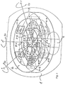
- Fig. 1 schematisch in pespektivischer Darstellung die wesentlichen Teile einer in einer Kunststoffkugel untergebrachten, opto-elektronischen Anordnung gemäß der Erfindung und
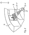
- Fig. 2 einen vergrößerten Ausschnitt aus der perspektivischen Darstellung der Fig. 1, aus welcher die Zuordnung der wesentlichen Teile der erfindungsgemäßen opto-elektronischen Anordnung zu ersehen sind.
- Fig. 1 shows schematically in perspective the essential parts of an opto-electronic arrangement housed in a plastic ball according to the invention and
- Fig. 2 is an enlarged detail from the perspective view of FIG. 1, from which the assignment of the essential parts of the opto-electronic arrangement according to the invention can be seen.
Wie dem Ausschnitt der Fig. 2 zu entnehmen ist, ist eine lichtemittierende Einrichtung, vorzugsweise in Form einer lichtemittierenden Diode 2-1 auf einer nur schematisch angedeuteten Halterungseinrichtung 2 angebracht. Der lichtemittierenden Diode 2-1 ist in einem fest vorgegebenen Abstand eine in einem zylindrischen Ring 3 ausgebildete Schlitzblende zugeordnet, welche in dem Ausschnitt der Fig. 2 die waagrecht verlaufende Schlitzblende 3-1 ist. Senkrecht zu der Schlitzrichtung der jeweiligen Schlitzblende ist ein positionsempfindlicher Detektor (PSD) 4-1 vorgesehen, welcher in dem in Fig. 2 wiedergegebenen Ausschnitt an einem zylindrischen Ring 4 angebracht ist.As can be seen from the detail in FIG. 2, a light-emitting device, preferably in the form of a light-emitting diode 2-1, is attached to a
Die in Fig. 2 dargestellten und in der beschriebenen Weise einander zugeordneten Elemente, nämlich die lichtemittierende Diode 2-1, die Schlitzblende 3-1 und der senkrecht zu deren Schlitzrichtung angeordnete, positionsempfindliche Detektor 4-1 bilden gewissermaßen ein Basismeßsystem, welches, wie aus der perspektivischen Darstellung der Fig. 1 zu ersehen ist, mindestens sechsmal benötigt wird.The elements shown in FIG. 2 and assigned to one another in the manner described, namely the light-emitting diode 2-1, the slit diaphragm 3-1 and the position-sensitive detector 4-1 arranged perpendicular to their slit direction form a basic measuring system, as it were the perspective view of FIG. 1 can be seen, is needed at least six times.
Bei der erfindungsgemäßen opto-elektronischen Anordnung sind die sechs lichtemittierenden Einrichtungen, vorzugsweise in Form von sechs lichtemittierenden Dioden 2-1 bis 2-6 in einer Ebene angeordnet, wobei den lichtemittierenden Einrichtungen in einem festen Abstand eweils eine Schlitzblende 3-1 bis 3-6 zugeordnet ist; hierbei sind benachbarte Schlitzblenden in dem Ring 3 jeweilsum 90° gegeneinander versetzt ausgebildet. So ist beispielsweise die Schlitzblende 3-1 waagrecht und die beiden benachbarten Schlitzblenden 3-2 bzw. 3-6 sind senkrecht dazu ausgerichtet; diese Beziehung gilt dann auch für alle übrigen Schlitzblenden und die ihnen jeweils benachbarten Schlitzblenden.In the optoelectronic arrangement according to the invention, the six light-emitting devices, preferably in the form of six light-emitting diodes 2-1 to 2-6, are arranged in one plane, the light-emitting devices each having a slit diaphragm 3-1 to 3-6 at a fixed distance assigned; adjacent slot diaphragms in the
In der in Fig. 1 schematisch wiedergegebenen Ausführung sind die mindestens sechs positionsempfindlichen Detektoren 4-1 bis 4-6 an einem zylindrischen Ring 4 bezüglich der ihnen zugeordneten Schlitzblenden 3-1 bis 3-6 entsprechend ausgerichtet. Ferner ist der Ring 4 mit den sechs Detektoren 4-1 bis 4-6 fest auf der Innenseite einer Kunststoffkugel 1 angebracht. Da die sechs lichtemittierenden Dioden 2-1 bis 2-6 in Fig. 1 in einer schematisch als Zylinder angedeuteten Halterungseinrichtung 2 untergebracht sind, welche ihrerseits über einer Stütze 6 stationär angeordnet ist, ist über die Kunststoffkugel 1 der mit ihr fest verbundene Ring 4 mit den daran angebrachten sechs Detektoren gegenüber der stationären Anordnung aus den sechs lichtemittierenden Einrichtungen 2-1 bis 2-6 und dem ihr fest zugeordneten Schlitzblendenring 3 bewegbar.In the embodiment shown schematically in FIG. 1, the at least six position-sensitive detectors 4-1 to 4-6 on a
Die stationäre, in Fig. 1 schematisch als Zylinder angedeutete Halterungseinrichtung 2 kann bei einer praktischen Ausführungsform beispielsweise als eine mit der stationären Stütze 6 fest verbundene Scheibe ausgeführt sein, deren Durchmesser etwa dem Außendurchmesser des die Detektoren 4-1 bis 4-6 tragenden Rings 4 entspricht und welche über oder unter diesem Ring 4 angeordnet sein kann.In a practical embodiment, the
Hierbei sind dann zwischen dem Ring 4 und der scheibenförmigen Halterungseinrichtung 2 Federelemente, vorzugsweise in Form von Schraubenfedern, vorgesehen, welche mittels Schraubbolzen sowohl dem Ring als auch der scheibenförmigen Halterungseinrichtung fest zugeordnet sind. Vorzugsweise durch solche Schraubenfedern ist dann erreicht, daß der die Detektoren 4-1 bis 4-6 tragende Ring 4 über die Kunststoffkugel 1 bezüglich der stationären Anordnung der lichtemittierenden Einrichtungen 2-1 bis 2-6 und dem fest zugeordneten Schlitzblendenring 3 bewegbar ist und nach jeder Verschiebung oder Winkeldrehung jeweils wieder in seine Ausgangslage zurückkehrt.In this case, spring elements, preferably in the form of helical springs, are then provided between the
In der schematischen perspektivischen Darstellung der Fig. 1 sind zur Abschirmung der einzelnen lichtemittierenden Dioden 2-1 bis 2-6 zwischen ihnen jeweils in radialer Richtung verlaufende Abschirmstege 5-1 bis 5-6 dargestellt. Solche Stege können jedoch entfallen, wenn die einzelnen lichtemittierenden Dioden aufgrund ihrer Ausbildung oder aufgrund einer entsprechenden Anordnung oder Unterbringung auf bzw. in der Halterungseinrichtung 2 von sich aus entsprechend abgeschirmt sind, so daß sichergestellt ist, daß nur jeweils Licht der vorgesehenen radial gegenüberliegenden lichtemittierenden Einrichtung über die ihr fest zugeordnete Schlitzblende auf den jeweiligen positionsempfindlichen Detektor fällt.In the schematic perspective illustration of FIG. 1, shielding webs 5-1 to 5-6 running between them in the radial direction are shown for shielding the individual light-emitting diodes 2-1 to 2-6. Such webs can, however, be omitted if the individual light-emitting diodes are shielded from their own accord due to their design or due to a corresponding arrangement or placement on or in the
Aufgrund der gewählten, bevorzugten Gesamtanordnung ist ein räumlich kompakteres Meßsystem geschaffen, als es bei einer Umkehr der optischen Zuordnung möglich wäre, welche jedoch prinzipiell genauso möglich ist.Due to the selected, preferred overall arrangement, a spatially more compact measuring system is created than would be possible with a reversal of the optical assignment, which, however, is also possible in principle.
Die mindestens sechs anhand von Fig. 2 beschriebenen Basismeßsysteme sind in gleichen Winkelabständen voneinander, d.h. unter einem Winkel von 60°, in einer Ebene angeordnet, und weisen, wie bereits beschrieben, abwechselnd zu dieser Ebene horizontal und vertikal ausgerichtete Schlitzblenden 3-1 bis 3-6 auf. Wie aus der Lage der einzelnen Schlitzblenden und der durch Schrauffur hervorgehobenen, von den lichtemittierenden Dioden 2-1 bis 2-6 ausgehenden Ebenen zu ersehen ist, sind die Detektorachsen der einzelnen positionsempfindlichen Detektoren 4-1 bis 4-6 immer senkrecht zu den ihnen zugeordneten Schlitzblenden 3-1 bis 3-6 ausgerichtet.The at least six basic measuring systems described with reference to Fig. 2 are at equal angular distances from one another, i.e. at an angle of 60 °, arranged in one plane, and, as already described, alternately to this plane horizontally and vertically aligned slit diaphragms 3-1 to 3-6. As can be seen from the position of the individual slit diaphragms and the planes highlighted by the hatching, emanating from the light-emitting diodes 2-1 to 2-6, the detector axes of the individual position-sensitive detectors 4-1 to 4-6 are always perpendicular to those assigned to them Slotted diaphragms 3-1 to 3-6 aligned.
Dadurch erhält jedes einzelne Basismeßsystem eine selektive Meßempfindlichkeit für eine in der Detektorachsenrichtung erfolgende Bewegung, während sowohl Bewegungen senkrecht zur Detektorachse aufgrund der schlitzförmigen Blenden als auch Bewegungen senkrecht zu der Detektoroberfläche vollständig entkoppelt möglich sind, wobei jedoch durch solche Bewegungen keine Meßsignale erzeugt werden.This gives each individual basic measuring system a selective measuring sensitivity for a movement in the detector axis direction, while both movements perpendicular to the detector axis due to the slit-shaped diaphragms and also movements perpendicular to that Detector surface are completely decoupled, but no measurement signals are generated by such movements.
Durch dio in dio sogenannte Mebebene versetzte, mindestens sechstache Anordnung aer Fig. schematisch dargestellten Basismeßsysteme ist eine vollständige Erfassung aller sechs möglichen Bewegungskomponenten, nämlich von drei Verschiebungen in Richtung der drei Achsen des Koordinatensystems und von drei Winkelbewegungen um diese drei Achsen, erreicht. Die mindestens sechs positionsempfindlichen Detektoren 4-1 bis 4-6 sind am dem zylindrischen Ring 4 so angebracht, daß der Nullpunkt ihrer Detektorflächen eine gemeinsame Ebene, die bereits erwähnte Meßebene, bildet. Da die Kunstoffkugel 1 fest an dem die Detektoren 4-1 bis 4-6 tragenden Ring 4 angebracht ist, und da dieser Ring 4 wiederum, wie oben im einzelnen ausgeführt, vorzugsweise mittels Federelementen mit der stationären Halterungseinrichtung verbunden ist, welche die Anordnung aus den sechs lichtemittierenden Einrichtungen 2-1 bis 2-6 und die diesen fest zugeordneten Schlitzblenden 3-1 bis 3-6 trägt, halten diese Federelemente das gesamte Meßsystem in der mechanischen Nullstellung, wenn keine Kommandos auf die Kugel 1 aufgebracht werden.A basic measurement system, shown schematically and offset at least six times in the so-called measuring plane, achieves a complete detection of all six possible movement components, namely of three displacements in the direction of the three axes of the coordinate system and of three angular movements about these three axes. The at least six position-sensitive detectors 4-1 to 4-6 are attached to the
Hierbei läßt sich durch Variation der Federeigenscaften (deren Steifigkeit) die Betriebscharakteristik der Kugel in weiten Grenzen beeinflussen. Bei Verwendung von verhältnismäßig weichen Federelementen wirkt die Kuge 1 eher als ein wegempfindlicher Sensor, während bei Verwendung von härteren Fedeelementen Kommandos mehr durch Ausüben von Kräften und Momenten erteilt werden.By varying the spring properties (their stiffness), the operating characteristics of the ball can be influenced within wide limits. When using relatively soft spring elements, the
Aufgrund der Verwendung von nicht nur einer Lichtquelle für alle Detektorsysteme, sondern von jeweils einer eigenen, jedem sogenannten Basismeßsystem zugeordneten Lichtquelle kann die erforderliche Signalaufbereitungselektronik sehr einfach realisiert werden. Die interessierende Lage des auf den jeweiligen positionsempfindlichen Detektor treffenden Lichtschlitzes läßt sich aus dessen beide Ausgangsströmen (11, 12), welche zuvor in proportionale Spannungen (U1, U2) umgewandelt werden, über die bekannte Beziehung (U1-U2)/(U1+U2) ermitteln. Dieser Quotient ist jedoch analog technisch nur mit einem verhältnismäßig großen Aufwand zu bestimmen. Die Erfassung sowie die Digitalisierung der Spannungen U1 und U2 und die anschließende digitale Bestimmung des Ausdrucks bedingen im Ergebnis zusätzliche Quantisierungsfehler, insbesondere dann, wenn preiswerte Wandler mit einem niedrigen Auflösungsvermögen verwendet werden sollen.Due to the use of not only one light source for all detector systems, but rather each of its own light source assigned to each so-called basic measuring system, the required signal processing electronics can be implemented very easily. The position of interest of the light slit striking the respective position-sensitive detector can be determined from its two output currents (11, 12), which are previously converted into proportional voltages (U1, U2), via the known relationship (U1-U2) / (U1 + U2 ) determine. Analogously, however, this quotient can only be determined technically with a relatively large outlay. The detection as well as the digitization of the voltages U1 and U2 and the subsequent digital determination of the expression result in additional quantization errors, in particular if inexpensive converters with a low resolution are to be used.
Wie schon erwähnt, ist diese Schwierigkeit bei der erfindungsgemäßen opto-elektronischen Anordnung dadurch beseitigt, daß jedem positionsempfindlichen Detektor eine eigene Lichtquelle zugeordnet ist, welche durch eine einfache Regelelektronik angesteuert wird. Mit dieser Regelelektronik wird die Summe (11+12) der beiden Detektorströme 11 und 12 gemessen, und die Strahlungsintensität der zugeordneten Lichtquelle wird so geregelt, daß unabhängig von dem Abstand und der Lage der zugeordneten Schlitzblende (3-1 bis 3-6) diese Summe immer einem fest eingestellten Wert entspricht, wobei dieser Wert für alle mindestens sechs Basismeßsysteme gleich ist.As already mentioned, this difficulty is eliminated in the optoelectronic arrangement according to the invention in that each position-sensitive detector is assigned its own light source, which is controlled by simple control electronics. With this control electronics, the sum (11 + 12) of the two detector currents 11 and 12 is measured, and the radiation intensity of the assigned light source is controlled so that it is independent of the distance and the position of the assigned slit diaphragm (3-1 to 3-6) Sum always corresponds to a fixed value, whereby this value is the same for all at least six basic measuring systems.
Mit Hilfe dieser Regelelektronik werden dann beispielsweise unterschiedliche Detektor-Empfindlichkeiten, unterschiedliche Leuchtdioden-Wirkungsgrade, Toleranzen in den elektronischen Bauelementen sowie Temperaturdriften automatisch und schnell ausgeregelt. Auf diese Weise ist kein zusätzlicher Abgleich erforderlich, und er kann somit entfallen. Das gewünschte Lagesignal läßt sich dann in einfacher Weise hochgenau lediglich durch eine Differenzbildung (U1-U2) der beiden zu den Ausgangsströmen 11 und 12 der Detektoren proportionalen Spannungen U1 und U2 bestimmen.With the aid of this control electronics, for example, different detector sensitivities, different light-emitting diode efficiencies, tolerances in the electronic components and temperature drifts are then automatically and quickly corrected. In this way, no additional adjustment is required and can therefore be omitted. The desired position signal can then be determined in a simple, highly precise manner simply by forming a difference (U1-U2) between the two voltages U1 and U2 proportional to the output currents 11 and 12 of the detectors.
Die so gewonnenen mindestens sechs Lagespannungen UL1 bis UL6 der einzelnen positionsempfindlichen Detektoren 4-1 bis 4-6 werden digitalisiert und einem Mikrocomputer zugeführt, welcher dann beispielsweise über das nachstehend wiedergegebene, einfache Gleichungssystem die insgesamt sechs Verschiebungen und Winkeldrehungen errechnet:

Durch Betriebsversuche mit einem Prototyp der erfindungsgemäßen opto-elektronischen Anordnung konnte die einwandfreie Funktion der in eine Kunststoffkugel 1 eingebauten Meßanordnung nachgewiesen werden. Beispielsweise ließ sich ein Roboter mit sechs Freiheitsgraden, in der Bewegung sauber entkoppelt, auf geraden Bahnen im Raum führen. Ebenso konnte die Orientierung der Hand kommandiert werden, ohne daß translatorische Bewegungen auftraten.Through operational tests with a prototype of the optoelectronic arrangement according to the invention, the perfect functioning of the measuring arrangement built into a
Die erfindungsgemäße opto-elektronische Anordnung ist auch für hochgenaue Positionieraufgaben vorzüglich geeignet, wie sie beispielsweise bei Robotern und Werkzeugmaschinen vorkommen. In einem solchen Fall sind dann die Anordnung aus den lichtemittierenden Einrichtungen und der ihr fest zugeordnete Blendenteil sowie der Ring mit den positionsempfindlichen Detektoren nicht mit Federn verbunden, sondern getrennt an den beiden auszurichtenden Maschinenteilen angebracht. Mit Hilfe der erfindungsgemäßen opto-elektronischen Anordnung und der nachgeschalteten Regelelektronik können dann die Teile in allen sechs Freiheitsgraden ausgerichtet werden, bzw. die verbleibenden Ausrichtfehler hochgenau festgestellt werden.The optoelectronic arrangement according to the invention is also excellently suitable for high-precision positioning tasks, such as occur, for example, in robots and machine tools. In one In such a case, the arrangement of the light-emitting devices and the diaphragm part permanently assigned to them, as well as the ring with the position-sensitive detectors are not connected with springs, but rather are attached separately to the two machine parts to be aligned. With the help of the optoelectronic arrangement according to the invention and the downstream control electronics, the parts can then be aligned in all six degrees of freedom, or the remaining alignment errors can be determined with high precision.
Ohne Abwandlung des Grundgedankens der erfindungsgemäßen opto-elektronischen Anordnung können auch großflächige Detektoren verwendet werden, um dadurch größere Wege- und Winkelmeßbereiche zu erhalten. In diesem Fall kann dann auch der Einsatz von Linsensystemen zur Lichtstrahlbündelung oder zu dessen Abbildung auf einer Detektorfläche sinnvoll sein.Without modifying the basic idea of the optoelectronic arrangement according to the invention, large-area detectors can also be used in order to obtain larger path and angle measuring ranges. In this case, the use of lens systems for bundling light beams or for imaging them on a detector surface can also be useful.
Claims (3)
Priority Applications (1)
| Application Number | Priority Date | Filing Date | Title |
|---|---|---|---|
| AT87104909T ATE55642T1 (en) | 1986-04-04 | 1987-04-02 | OPTOELECTRONIC ARRANGEMENT HOUSED IN A PLASTIC BALL. |
Applications Claiming Priority (2)
| Application Number | Priority Date | Filing Date | Title |
|---|---|---|---|
| DE3611337 | 1986-04-04 | ||
| DE19863611337 DE3611337A1 (en) | 1986-04-04 | 1986-04-04 | OPTO-ELECTRONIC ARRANGEMENT HOUSED IN A PLASTIC BALL |
Publications (2)
| Publication Number | Publication Date |
|---|---|
| EP0240023A1 EP0240023A1 (en) | 1987-10-07 |
| EP0240023B1 true EP0240023B1 (en) | 1990-08-16 |
Family
ID=6297941
Family Applications (1)
| Application Number | Title | Priority Date | Filing Date |
|---|---|---|---|
| EP87104909A Expired - Lifetime EP0240023B1 (en) | 1986-04-04 | 1987-04-02 | Opto-electronic arrangement put in a plastics bowl |
Country Status (6)
| Country | Link |
|---|---|
| US (1) | US4785180A (en) |
| EP (1) | EP0240023B1 (en) |
| JP (1) | JPS6340803A (en) |
| AT (1) | ATE55642T1 (en) |
| DE (2) | DE3611337A1 (en) |
| ES (1) | ES2016296B3 (en) |
Cited By (4)
| Publication number | Priority date | Publication date | Assignee | Title |
|---|---|---|---|---|
| DE19952560A1 (en) * | 1999-11-01 | 2001-05-10 | Deutsch Zentr Luft & Raumfahrt | Method and system for adjusting and re-adjusting parts of drivers seat or supporting structures with manual pressure sensitive control unit |
| DE19947733A1 (en) * | 1999-10-05 | 2001-08-09 | Deutsch Zentr Luft & Raumfahrt | Device for accurately measuring and determining vehicle seat occupant data, such as weight and size, using force and moment sensors placed on or near the seat |
| DE10034569A1 (en) * | 2000-07-14 | 2002-01-31 | Deutsch Zentr Luft & Raumfahrt | Device for detecting relative movement of object has detection unit on intermediate part with force-torque sensor in center of input flange and not in contact with intermediate part |
| EP1291616A2 (en) | 2001-09-05 | 2003-03-12 | Deutsches Zentrum für Luft- und Raumfahrt e.V. | Device for detecting relative motion of two objects |
Families Citing this family (76)
| Publication number | Priority date | Publication date | Assignee | Title |
|---|---|---|---|---|
| DE3827719A1 (en) * | 1988-08-16 | 1990-02-22 | Dietmar Klinger | OPTOELECTRONIC MEASUREMENT ARRANGEMENT |
| US4952919A (en) * | 1989-04-06 | 1990-08-28 | Tektronix, Inc. | Trackball mechanism |
| DE4021455A1 (en) * | 1989-11-27 | 1991-05-29 | Stribel Gmbh | Optoelectronic device for measuring deflection magnitude and direction - sends light with variable intensity to sensor with several receiver surfaces, microprocessor deriving deflection signal |
| US5359703A (en) * | 1990-08-02 | 1994-10-25 | Xerox Corporation | Moving an object in a three-dimensional workspace |
| DE4108388C2 (en) * | 1991-03-15 | 2000-10-12 | Wabco Gmbh & Co Ohg | Device for contactless detection of at least two positions of a switching element |
| US5177352A (en) * | 1991-06-06 | 1993-01-05 | The United States Of America As Represented By The United States Department Of Energy | Integrated optical tamper sensor with planar waveguide |
| US5704015A (en) * | 1992-10-20 | 1997-12-30 | Fuji Photo Film Co., Ltd. | Optical operation element, optical data processing circuit and photoelectric operation element |
| DE4308456C2 (en) * | 1993-03-17 | 1996-03-28 | Ems Technik Gmbh | Device for determining the position of a positioning body relative to a reference body |
| DE4409530C2 (en) * | 1993-03-19 | 1999-05-20 | Basys Ges Fuer Anwender Und Sy | Non-contact measuring device and its use for determining the two-dimensionally defined location of a measuring body |
| DE4340941C2 (en) * | 1993-12-01 | 1996-07-11 | Stn Atlas Elektronik Gmbh | Motion sensor for simulated motion in a virtual environment |
| NL1003175C2 (en) * | 1996-05-21 | 1997-11-25 | Wilhelmus Petrus Van Vliet | Rapid three-dimensional co-ordinate measurement system |
| DE19632273A1 (en) * | 1996-08-09 | 1998-02-12 | Helge Zwosta | Body sensors |
| EP0941507A1 (en) | 1996-12-04 | 1999-09-15 | Martin Sundin | Position measuring device for detecting displacements with at least three degrees of freedom |
| US6195083B1 (en) * | 1997-11-14 | 2001-02-27 | Septimiu E. Salcudean | Active joystick with optical positions sensor |
| DE19823903A1 (en) * | 1998-05-28 | 1999-12-02 | Sensor Instr Gmbh | System for simultaneous measuring of torque and angle of rotation of shaft |
| EP0979990B1 (en) * | 1998-08-10 | 2002-05-22 | Deutsches Zentrum für Luft- und Raumfahrt e.V. | Device for starting technical controlling operations and/or for starting the execution of technical functions |
| DE29901998U1 (en) * | 1999-02-05 | 2000-03-16 | Honeywell Ag | Position detection device |
| DE10029173A1 (en) * | 2000-06-19 | 2002-01-03 | Deutsch Zentr Luft & Raumfahrt | Method and arrangement for commanding control operations for kinematic movements of an object using a hand-operated input device |
| DE10045117C2 (en) * | 2000-09-13 | 2002-12-12 | Bernd Von Prittwitz | Method and device for real-time geometry control |
| DE10125575A1 (en) * | 2001-05-25 | 2002-12-12 | Deutsch Zentr Luft & Raumfahrt | Input device with a person-operated operating part for controlling the positioning of an object |
| DE10158776B4 (en) * | 2001-11-30 | 2004-05-13 | 3Dconnexion Gmbh | Arrangement for detecting relative movements or relative positions of two objects |
| DE10158775B4 (en) | 2001-11-30 | 2004-05-06 | 3Dconnexion Gmbh | Arrangement for detecting relative movements or relative positions of two objects |
| DE10158777B4 (en) | 2001-11-30 | 2004-05-06 | 3Dconnexion Gmbh | Arrangement for detecting relative movements or relative positions of two objects |
| WO2003088204A1 (en) | 2002-04-12 | 2003-10-23 | Obermeyer Henry K | Multi-axis joystick and transducer means therefore |
| DE10246031A1 (en) * | 2002-10-02 | 2004-04-15 | 3Dconnexion Gmbh | Position-and/or movement-sensor for relative positions of two objects, includes protective spring device which elastically joins first module with first object |
| FR2847995B1 (en) * | 2002-11-28 | 2005-05-13 | Ge Med Sys Global Tech Co Llc | METHOD FOR PROCESSING CONTROL INFORMATION TRANSMITTED BY A 3D MODELING IMAGE MANIPULATION DEVICE, AND INSTALLATION FOR VISUALIZING MEDICAL IMAGES IN INTERVENTION AND / OR EXAMINATION ROOM |
| DE10325284A1 (en) * | 2003-06-04 | 2005-01-13 | 3Dconnexion Gmbh | Multidimensional input device for navigation and selection of visual objects |
| DE10334126B4 (en) * | 2003-07-25 | 2007-06-06 | 3Dconnexion Gmbh | Error correction with force / moment sensors |
| DE102004063975B4 (en) | 2004-10-22 | 2018-05-30 | Société Civile "Galileo 2011" | Optoelectronic arrangement for detecting relative movements or relative positions of two objects |
| DE102004051565B4 (en) * | 2004-10-22 | 2014-06-26 | Société Civile "Galileo 2011" | Optoelectronic arrangement for detecting relative movements or relative positions of two objects as well as force and / or moment sensor, pan / zoom sensor and PC keyboard with such an arrangement |
| DE102004064259B3 (en) | 2004-10-22 | 2018-03-08 | Société Civile "Galileo 2011" | Optoelectronic arrangement for detecting relative movements or relative positions of two objects |
| EP1669842A1 (en) * | 2004-12-02 | 2006-06-14 | 3Dconnexion GmbH | Input device with different modes |
| DE102006008840B4 (en) * | 2006-02-25 | 2009-05-14 | Fraunhofer-Gesellschaft zur Förderung der angewandten Forschung e.V. | Cylindrical object lighting device, surface inspection method and computer program product performed thereby |
| JP4955286B2 (en) * | 2006-03-07 | 2012-06-20 | ミネベア株式会社 | External force detection device |
| JP5113762B2 (en) | 2006-12-04 | 2013-01-09 | 株式会社島精機製作所 | 3D motion input device |
| DE102006058805B4 (en) * | 2006-12-13 | 2011-12-22 | Spacecontrol Gmbh | Device for the input of movements and / or detection of forces |
| DE102006058806A1 (en) * | 2006-12-13 | 2008-06-19 | Spacecontrol Gmbh | Device for measuring acceleration of object, has elastic element with two areas, and deflections of flexible element are measured by slot shutter, light source and position-sensitive detector |
| DE102008019144B4 (en) | 2008-04-16 | 2016-12-01 | Spacecontrol Gmbh | Device for inputting control signals for moving an object |
| US9870021B2 (en) | 2009-04-15 | 2018-01-16 | SeeScan, Inc. | Magnetic manual user interface devices |
| WO2011146668A2 (en) | 2010-05-18 | 2011-11-24 | Seektech, Inc. | User interface devices, apparatus, and methods |
| EP2606411B1 (en) | 2010-08-20 | 2014-07-30 | SeeScan, Inc. | Magnetic sensing user interface method, device and computer-readable medium |
| WO2012051357A1 (en) | 2010-10-12 | 2012-04-19 | Mark Olsson | Magnetic thumbstick user interface devices |
| US9134817B2 (en) | 2010-11-08 | 2015-09-15 | SeeScan, Inc. | Slim profile magnetic user interface devices |
| EP3043231A1 (en) | 2010-12-02 | 2016-07-13 | SeeScan, Inc. | Magnetically sensed user interface devices |
| DE102010062458A1 (en) | 2010-12-06 | 2012-06-06 | W. Gessmann Gmbh | Operating device for e.g. working machine, generates measurement signals indicating relative position of detector of sensor units and associated reference point along two detection axes by actuating operating unit |
| US9678577B1 (en) | 2011-08-20 | 2017-06-13 | SeeScan, Inc. | Magnetic sensing user interface device methods and apparatus using electromagnets and associated magnetic sensors |
| DE102011119014A1 (en) * | 2011-11-14 | 2013-05-16 | Jens Hansen | Writer |
| US9690390B2 (en) | 2013-05-17 | 2017-06-27 | SeeScan, Inc. | User interface devices |
| US9123506B2 (en) | 2013-06-10 | 2015-09-01 | Fei Company | Electron beam-induced etching |
| DE102017206025A1 (en) | 2017-04-07 | 2018-10-11 | Deutsches Zentrum für Luft- und Raumfahrt e.V. | Magnetic arrangement for detecting relative movements or relative positions |
| DE102017110632A1 (en) | 2017-05-16 | 2018-11-22 | Deutsches Zentrum für Luft- und Raumfahrt e.V. | Input device and use of such |
| US11428589B2 (en) * | 2017-10-16 | 2022-08-30 | Saf-Holland, Inc. | Displacement sensor utilizing ronchi grating interference |
| DE102018205159A1 (en) * | 2018-04-05 | 2019-10-10 | Deutsches Zentrum für Luft- und Raumfahrt e.V. | 3D input device |
| US10925598B2 (en) | 2018-07-16 | 2021-02-23 | Ethicon Llc | Robotically-assisted surgical suturing systems |
| US10871384B2 (en) | 2019-02-26 | 2020-12-22 | Thomas P. Moyer | Apparatus and methods utilizing emissive patterns to determine positional information |
| EP3937818A1 (en) | 2019-03-15 | 2022-01-19 | Cilag GmbH International | Input controls for robotic surgery |
| US11690690B2 (en) | 2019-03-15 | 2023-07-04 | Cilag Gmbh International | Segmented control inputs for surgical robotic systems |
| WO2020188391A1 (en) | 2019-03-15 | 2020-09-24 | Ethicon Llc | Robotic surgical controls having feedback capabilities |
| US11284957B2 (en) | 2019-03-15 | 2022-03-29 | Cilag Gmbh International | Robotic surgical controls with force feedback |
| US11471229B2 (en) | 2019-03-15 | 2022-10-18 | Cilag Gmbh International | Robotic surgical systems with selectively lockable end effectors |
| US11583350B2 (en) | 2019-03-15 | 2023-02-21 | Cilag Gmbh International | Jaw coordination of robotic surgical controls |
| US11490981B2 (en) | 2019-03-15 | 2022-11-08 | Cilag Gmbh International | Robotic surgical controls having feedback capabilities |
| US11701190B2 (en) | 2019-03-15 | 2023-07-18 | Cilag Gmbh International | Selectable variable response of shaft motion of surgical robotic systems |
| US11666401B2 (en) | 2019-03-15 | 2023-06-06 | Cilag Gmbh International | Input controls for robotic surgery |
| WO2021050199A1 (en) * | 2019-09-10 | 2021-03-18 | National Oilwell Varco, L.P. | Non-contact rotary communication system |
| US11744667B2 (en) | 2019-12-30 | 2023-09-05 | Cilag Gmbh International | Adaptive visualization by a surgical system |
| US11284963B2 (en) | 2019-12-30 | 2022-03-29 | Cilag Gmbh International | Method of using imaging devices in surgery |
| US11832996B2 (en) | 2019-12-30 | 2023-12-05 | Cilag Gmbh International | Analyzing surgical trends by a surgical system |
| US11648060B2 (en) | 2019-12-30 | 2023-05-16 | Cilag Gmbh International | Surgical system for overlaying surgical instrument data onto a virtual three dimensional construct of an organ |
| US11896442B2 (en) | 2019-12-30 | 2024-02-13 | Cilag Gmbh International | Surgical systems for proposing and corroborating organ portion removals |
| US11219501B2 (en) | 2019-12-30 | 2022-01-11 | Cilag Gmbh International | Visualization systems using structured light |
| US11776144B2 (en) | 2019-12-30 | 2023-10-03 | Cilag Gmbh International | System and method for determining, adjusting, and managing resection margin about a subject tissue |
| US11759283B2 (en) | 2019-12-30 | 2023-09-19 | Cilag Gmbh International | Surgical systems for generating three dimensional constructs of anatomical organs and coupling identified anatomical structures thereto |
| US11813746B2 (en) | 2020-12-30 | 2023-11-14 | Cilag Gmbh International | Dual driving pinion crosscheck |
| DE102021106698A1 (en) | 2021-03-18 | 2022-09-22 | Deutsches Zentrum für Luft- und Raumfahrt e.V. | 3D input device, mobile device and 3D input device |
| WO2023073664A1 (en) | 2021-11-01 | 2023-05-04 | Cilag Gmbh International | Devices, systems, and methods for detecting tissue and foreign objects during a surgical operation |
Citations (2)
| Publication number | Priority date | Publication date | Assignee | Title |
|---|---|---|---|---|
| US3628394A (en) * | 1970-02-09 | 1971-12-21 | Sperry Rand Corp | Operator-manipulative control apparatus |
| US3921445A (en) * | 1973-10-15 | 1975-11-25 | Stanford Research Inst | Force and torque sensing method and means for manipulators and the like |
Family Cites Families (4)
| Publication number | Priority date | Publication date | Assignee | Title |
|---|---|---|---|---|
| DE2015982A1 (en) * | 1970-03-31 | 1971-10-14 | Siemens Ag | Device for recording measured value-corresponding deflections of a light beam |
| US3814199A (en) * | 1972-08-21 | 1974-06-04 | Cleveland Machine Controls | Motor control apparatus adapted for use with a motorized vehicle |
| DE2309682A1 (en) * | 1973-02-27 | 1974-09-26 | Messerschmitt Boelkow Blohm | DEVICE FOR GENERATING SIGNALS WITH A CONTROL STICK |
| US4607159A (en) * | 1983-12-27 | 1986-08-19 | North American Philips Consumer Electronics Corp. | Optical joystick controller with intersecting spring means |
-
1986
- 1986-04-04 DE DE19863611337 patent/DE3611337A1/en not_active Withdrawn
-
1987
- 1987-04-01 JP JP62080872A patent/JPS6340803A/en active Granted
- 1987-04-01 US US07/033,512 patent/US4785180A/en not_active Expired - Lifetime
- 1987-04-02 EP EP87104909A patent/EP0240023B1/en not_active Expired - Lifetime
- 1987-04-02 ES ES87104909T patent/ES2016296B3/en not_active Expired - Lifetime
- 1987-04-02 DE DE8787104909T patent/DE3764287D1/en not_active Expired - Lifetime
- 1987-04-02 AT AT87104909T patent/ATE55642T1/en not_active IP Right Cessation
Patent Citations (2)
| Publication number | Priority date | Publication date | Assignee | Title |
|---|---|---|---|---|
| US3628394A (en) * | 1970-02-09 | 1971-12-21 | Sperry Rand Corp | Operator-manipulative control apparatus |
| US3921445A (en) * | 1973-10-15 | 1975-11-25 | Stanford Research Inst | Force and torque sensing method and means for manipulators and the like |
Cited By (10)
| Publication number | Priority date | Publication date | Assignee | Title |
|---|---|---|---|---|
| DE19947733A1 (en) * | 1999-10-05 | 2001-08-09 | Deutsch Zentr Luft & Raumfahrt | Device for accurately measuring and determining vehicle seat occupant data, such as weight and size, using force and moment sensors placed on or near the seat |
| DE19947733B4 (en) * | 1999-10-05 | 2004-04-29 | 3Dconnexion Gmbh | Device for acquiring and evaluating characteristic data on a vehicle seat and related evaluation method |
| DE19952560A1 (en) * | 1999-11-01 | 2001-05-10 | Deutsch Zentr Luft & Raumfahrt | Method and system for adjusting and re-adjusting parts of drivers seat or supporting structures with manual pressure sensitive control unit |
| DE19952560C2 (en) * | 1999-11-01 | 2002-03-07 | Deutsch Zentr Luft & Raumfahrt | Method for adjusting and / or adjusting a motor vehicle seat, parts of the motor vehicle seat and / or devices supporting the driver and device for carrying out the method |
| DE10034569A1 (en) * | 2000-07-14 | 2002-01-31 | Deutsch Zentr Luft & Raumfahrt | Device for detecting relative movement of object has detection unit on intermediate part with force-torque sensor in center of input flange and not in contact with intermediate part |
| DE10034569B4 (en) * | 2000-07-14 | 2004-02-12 | Deutsches Zentrum für Luft- und Raumfahrt e.V. | Device for detecting relative movements of an object |
| EP1291616A2 (en) | 2001-09-05 | 2003-03-12 | Deutsches Zentrum für Luft- und Raumfahrt e.V. | Device for detecting relative motion of two objects |
| DE10143489A1 (en) * | 2001-09-05 | 2003-04-03 | Deutsch Zentr Luft & Raumfahrt | Arrangement for detecting relative movements of two objects |
| DE10143489C2 (en) * | 2001-09-05 | 2003-07-17 | Deutsch Zentr Luft & Raumfahrt | Arrangement for detecting relative movements of two objects |
| US6928886B2 (en) | 2001-09-05 | 2005-08-16 | Deutsches Zentrum Fur Luft-Und Raumfahrt E.V. | Arrangement for the detection of relative movements of two objects |
Also Published As
| Publication number | Publication date |
|---|---|
| ATE55642T1 (en) | 1990-09-15 |
| JPH0457202B2 (en) | 1992-09-10 |
| JPS6340803A (en) | 1988-02-22 |
| US4785180A (en) | 1988-11-15 |
| DE3764287D1 (en) | 1990-09-20 |
| DE3611337A1 (en) | 1987-10-22 |
| EP0240023A1 (en) | 1987-10-07 |
| ES2016296B3 (en) | 1990-11-01 |
Similar Documents
| Publication | Publication Date | Title |
|---|---|---|
| EP0240023B1 (en) | Opto-electronic arrangement put in a plastics bowl | |
| EP1761363B1 (en) | Auxiliary device and method for calibrating an optical measurement array which can be mounted on a manipulator | |
| DE2833272C3 (en) | Device for determining the position of a radiation source | |
| EP1195580A2 (en) | Device to monitor movements of an object | |
| EP0554711A1 (en) | Actuated support | |
| EP2729763A1 (en) | Correcting and/or preventing errors during the measurement of coordinates of a workpiece | |
| EP0847149A1 (en) | Device and method for aligning an optical emitter and receiver beam in satellite connections | |
| WO2008071251A2 (en) | Device for detecting movement and forces | |
| EP0102472A1 (en) | Device for linear measurement and angle measurement | |
| DE102015221599A1 (en) | machine tool | |
| CH672679A5 (en) | ||
| EP0064687A2 (en) | Device for measuring movements of the mandibles or condyles | |
| EP0671679A1 (en) | Method and device to measure without contact tridimensional objects based on optical triangulation | |
| DE3702330A1 (en) | DEVICE FOR CONTROLLING THE DIRECTION OF A RAY OF AN OPTICAL RADIATION | |
| DE3614122C2 (en) | ||
| DE1270826B (en) | Device for space scanning | |
| DE3439495A1 (en) | Electronically controllable flexibility | |
| EP0280110B1 (en) | Sensor with an integrated signal processor for one-to-three-dimensional positioning | |
| DE1473931A1 (en) | Device for the continuous determination of the actual position of a movable device in a reference coordinate system | |
| EP4061585A1 (en) | Calibration of an impedance control of a robot manipulator | |
| DE3919917A1 (en) | Optical sensor identifying and/or locating object - uses matrix of discret light sources at known spacing and main radiation angle | |
| DE102010037580A1 (en) | Linear motor position detection system | |
| EP0072386B1 (en) | Pulse generator for generating electronic pulse trains | |
| EP0334033A1 (en) | Position controlling means for sensor driven portal type robot | |
| EP1137973B1 (en) | Method and device for reducing temperature-related measurement deviations in parallel measurement systems |
Legal Events
| Date | Code | Title | Description |
|---|---|---|---|
| PUAI | Public reference made under article 153(3) epc to a published international application that has entered the european phase |
Free format text: ORIGINAL CODE: 0009012 |
|
| AK | Designated contracting states |
Kind code of ref document: A1 Designated state(s): AT DE ES FR GB IT NL SE |
|
| 17P | Request for examination filed |
Effective date: 19880507 |
|
| 17Q | First examination report despatched |
Effective date: 19890807 |
|
| RAP1 | Party data changed (applicant data changed or rights of an application transferred) |
Owner name: DEUTSCHE FORSCHUNGSANSTALT FUER LUFT- UND RAUMFAHR |
|
| GRAA | (expected) grant |
Free format text: ORIGINAL CODE: 0009210 |
|
| AK | Designated contracting states |
Kind code of ref document: B1 Designated state(s): AT DE ES FR GB IT NL SE |
|
| REF | Corresponds to: |
Ref document number: 55642 Country of ref document: AT Date of ref document: 19900915 Kind code of ref document: T |
|
| ITF | It: translation for a ep patent filed |
Owner name: JACOBACCI & PERANI S.P.A. |
|
| REF | Corresponds to: |
Ref document number: 3764287 Country of ref document: DE Date of ref document: 19900920 |
|
| GBT | Gb: translation of ep patent filed (gb section 77(6)(a)/1977) | ||
| ET | Fr: translation filed | ||
| PLBE | No opposition filed within time limit |
Free format text: ORIGINAL CODE: 0009261 |
|
| STAA | Information on the status of an ep patent application or granted ep patent |
Free format text: STATUS: NO OPPOSITION FILED WITHIN TIME LIMIT |
|
| 26N | No opposition filed | ||
| ITTA | It: last paid annual fee | ||
| EAL | Se: european patent in force in sweden |
Ref document number: 87104909.4 |
|
| REG | Reference to a national code |
Ref country code: GB Ref legal event code: IF02 |
|
| PGFP | Annual fee paid to national office [announced via postgrant information from national office to epo] |
Ref country code: DE Payment date: 20060320 Year of fee payment: 20 |
|
| PGFP | Annual fee paid to national office [announced via postgrant information from national office to epo] |
Ref country code: NL Payment date: 20060419 Year of fee payment: 20 |
|
| PGFP | Annual fee paid to national office [announced via postgrant information from national office to epo] |
Ref country code: FR Payment date: 20060420 Year of fee payment: 20 |
|
| PGFP | Annual fee paid to national office [announced via postgrant information from national office to epo] |
Ref country code: SE Payment date: 20060424 Year of fee payment: 20 Ref country code: AT Payment date: 20060424 Year of fee payment: 20 |
|
| PGFP | Annual fee paid to national office [announced via postgrant information from national office to epo] |
Ref country code: GB Payment date: 20060426 Year of fee payment: 20 |
|
| PGFP | Annual fee paid to national office [announced via postgrant information from national office to epo] |
Ref country code: ES Payment date: 20060428 Year of fee payment: 20 |
|
| PGFP | Annual fee paid to national office [announced via postgrant information from national office to epo] |
Ref country code: IT Payment date: 20060430 Year of fee payment: 20 |
|
| PG25 | Lapsed in a contracting state [announced via postgrant information from national office to epo] |
Ref country code: GB Free format text: LAPSE BECAUSE OF EXPIRATION OF PROTECTION Effective date: 20070401 |
|
| PG25 | Lapsed in a contracting state [announced via postgrant information from national office to epo] |
Ref country code: NL Free format text: LAPSE BECAUSE OF EXPIRATION OF PROTECTION Effective date: 20070402 |
|
| PG25 | Lapsed in a contracting state [announced via postgrant information from national office to epo] |
Ref country code: ES Free format text: LAPSE BECAUSE OF EXPIRATION OF PROTECTION Effective date: 20070403 |
|
| REG | Reference to a national code |
Ref country code: GB Ref legal event code: PE20 |
|
| NLV7 | Nl: ceased due to reaching the maximum lifetime of a patent |
Effective date: 20070402 |
|
| EUG | Se: european patent has lapsed | ||
| REG | Reference to a national code |
Ref country code: ES Ref legal event code: FD2A Effective date: 20070403 |