EP0238257A2 - Integrated calling directory - Google Patents
Integrated calling directory Download PDFInfo
- Publication number
- EP0238257A2 EP0238257A2 EP87302106A EP87302106A EP0238257A2 EP 0238257 A2 EP0238257 A2 EP 0238257A2 EP 87302106 A EP87302106 A EP 87302106A EP 87302106 A EP87302106 A EP 87302106A EP 0238257 A2 EP0238257 A2 EP 0238257A2
- Authority
- EP
- European Patent Office
- Prior art keywords
- message
- called party
- data
- directory
- processor
- Prior art date
- Legal status (The legal status is an assumption and is not a legal conclusion. Google has not performed a legal analysis and makes no representation as to the accuracy of the status listed.)
- Granted
Links
Images


Classifications
-
- H—ELECTRICITY
- H04—ELECTRIC COMMUNICATION TECHNIQUE
- H04M—TELEPHONIC COMMUNICATION
- H04M3/00—Automatic or semi-automatic exchanges
- H04M3/42—Systems providing special services or facilities to subscribers
- H04M3/487—Arrangements for providing information services, e.g. recorded voice services or time announcements
- H04M3/493—Interactive information services, e.g. directory enquiries ; Arrangements therefor, e.g. interactive voice response [IVR] systems or voice portals
- H04M3/4931—Directory assistance systems
-
- H—ELECTRICITY
- H04—ELECTRIC COMMUNICATION TECHNIQUE
- H04M—TELEPHONIC COMMUNICATION
- H04M1/00—Substation equipment, e.g. for use by subscribers
- H04M1/26—Devices for calling a subscriber
- H04M1/27—Devices whereby a plurality of signals may be stored simultaneously
-
- H—ELECTRICITY
- H04—ELECTRIC COMMUNICATION TECHNIQUE
- H04Q—SELECTING
- H04Q11/00—Selecting arrangements for multiplex systems
- H04Q11/04—Selecting arrangements for multiplex systems for time-division multiplexing
- H04Q11/0428—Integrated services digital network, i.e. systems for transmission of different types of digitised signals, e.g. speech, data, telecentral, television signals
-
- Y—GENERAL TAGGING OF NEW TECHNOLOGICAL DEVELOPMENTS; GENERAL TAGGING OF CROSS-SECTIONAL TECHNOLOGIES SPANNING OVER SEVERAL SECTIONS OF THE IPC; TECHNICAL SUBJECTS COVERED BY FORMER USPC CROSS-REFERENCE ART COLLECTIONS [XRACs] AND DIGESTS
- Y10—TECHNICAL SUBJECTS COVERED BY FORMER USPC
- Y10S—TECHNICAL SUBJECTS COVERED BY FORMER USPC CROSS-REFERENCE ART COLLECTIONS [XRACs] AND DIGESTS
- Y10S379/00—Telephonic communications
- Y10S379/904—Auto-calling
Definitions
- This invention relates to call directories and, in particular, to an integrated calling directory that resides on a user's personal computer.
- the personal computer is connected to a business communication system.
- the integrated calling directory has access to both directory information stored in the memory of the personal computer and centralized directory entries which are stored on the business communication system.
- Existing call directories are data bases generally found on an adjunct processor associated with the business communication system, which data base contains entries identifying an individual's name, address, organization, telephone number and other pertinent information.
- This centralized data base is accessible in the dial-up mode by subscribers who are served by the business communication system and by directory assistance operators who generally have their terminals hard-wired to an adjunct processor which contains the data base. An individual who wishes to obtain directory information from the data base must use one of these terminal access points to query the data base.
- Another call directory arrangement is found on personal computers where an individual can create their own personal call directory data base on their personal computer.
- This data.base contains entries similar to those contained in the centralized call directory data base.
- An additional capability is provided by the personal computer wherein the personal computer can output an identified individual's telephone number as dial pulse or Touch-Tone signals to originate a telephone call through the business communication system to the identified individual.
- files resident on the personal computer can be electronically transferred to an identified destination by the personal computer, under control of the subscriber, by the subscriber attaching an electronic mail address to the file and outputting same over the telephone lines through the business communication system to the identified destination.
- a significant disadvantage of these call directory arrangements is that the subscriber must perform a number of operations to transmit information to an identified individual or destination.
- the subscriber must access the call directory, input the identified individual's name, receive the entry from the call directory identifying the called party's room number, telephone number or electronic mail address.
- the subscriber must then take the received information and input it to their terminal or personal computer and indicate to the personal computer that this information must be used to originate a call connection or data transfer to the identified called party. This sequence of operations is time consuming and error prone.
- the integrated calling directory of the present invention eliminates the disadvantages of prior call directory arrangements by providing a software system which runs on a personal computer to automate the call directory and call origination function.
- the personal computer is interposed between an individual's telephone station set and the business communication system port circuit associated with the individual's telephone station set.
- the calling directory software both contains the individual's personal directory entries and has access to directory entries in the centralized business communication system data base which resides on an adjunct processor. These directory entries all contain called party identification data which includes information such as an individual's name, room number, electronic mail address, telephone number, type of terminal equipment associated with the called party, job title, etc.
- the integrated calling directory software responds to a message created by the subscriber on the personal computer by automatically analyzing the format of the message so created and certain message-dependent characteristics of the identified destination, such as type of terminal equipment.
- the calling directory software automatically selects the message transmission medium, accesses the appropriate directory entry to create the message header appropriate for the media selected by the calling-directory software, then transmits the completed message to the designated destination using the medium selected.
- the calling directory software can obtain the calling directory information either from an individualized data base residing on the personal computer or the centralized data base resident on the adjunct processor associated with the business communication system.
- the calling directory software automatically accesses the appropriate one of these two data bases to obtain the identification of the called party's destination description.
- the calling directory software of the present invention automates the entire message transmission function and eliminates the need for the subscriber to sequentially access a call directory then input the selected destination address into the personal computer and perform a call origination function.
- the integrated calling directory software combines all of these functions into a simple single feature activation by the subscriber. This combination eliminates a potential for improper or incorrect data entry and the time consuming sequential operations of the prior art call directory arrangements.
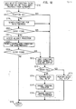
- FIG. 1 The business communication system of this invention is illustrated in FIG. 1.
- This system includes a plurality of terminal equipment Tll-T58 each of which is associated with a respective one of port circuits 111-158.
- This terminal equipment includes telephone station sets as well as digital terminal devices and computer facilities.
- a switching network 101 which comprises a time slot interchange circuit of the type illustrated in U. S. Patent No. 4,112,258, issued to H. G. Alles, September 5, 1978, is connected to a number of port data/control.interface circuits 171-175.
- Each port data/control interface circuit (eg. 171) shown in FIG. 1 serves eight port circuits (111-118) and functions to interface these port circuits with switching network 101 as well as system processor 100.
- Switching network 101 operates under control of system processor 100 and establishes communication connections among the terminal equipment by interconnecting the associated port circuits 111-158.
- the terminal equipment connected to port circuit 151 consists of the subject interface arrangement embodied in personal computer PC51 which is equipped with a DCP interface card and a digital telephone station set T51.
- Personal computer PC51 is interposed between port circuit 151 and digital telephone station set T51 and serves to provide communication services to digital telephone station set T51. This is accomplished by the use of DCP interface card 201 shown in block diagram form in FIG. 2.
- DCP interface card 201 is plugged into one of the expansion slots of personal computer PC51, where personal computer PC51 can be, for example, an AT&T PC6300 computer.
- DCP interface card 201 consists of two interface devices, telephone station set interface 202 and business communication system interface 206, which interconnect personal computer PC51 to digital telephone station set T51 and port circuit 151 respectively.
- Leads 203 and 205 connect telephone station set interface 202 and business communication system interface 206 respectively to bus communication controller 204.
- DCP interface card 201 receives all transmissions from port circuit 151 in business communication system interface 206 via communication leads TR51.
- Bus communication controller 204 receives an interrupt signal from business communication system interface 206 via leads 205 and reads the transmissions from port circuit 151 stored in business communication system interface 206.
- Bus communication controller 204 responds to these transmissions by generating an interrupt signal on PC BUS 207 to personal computer PC51.
- Personal computer PC51 serves the interrupt by reading the transmission stored in bus communication controller 204 via PC BUS 207, and storing the transmission in memory 208.
- Personal computer PC51 contains communication management application 210 to process the received transmission from port circuit 151.
- Device drivers 211 interfaces communication management application 210 with DCP interface card 201.
- Device drivers 211 contains two basic components: interrupt service routine 212 and application interface process 213.
- the functions of device drivers 211 are: process interrupts from DCP interface card 201; buffer and transfer data between DCP interface card 201 and communication management application 210; provide a simple interface to communication management application 210 for basic call setup and data transfer handle data call setup procedures with the business communication system as will be discussed below.
- processor 209 transmits control signals to bus communication controller 204 via PC BUS 207. These control signals are forwarded by bus communication controller 204 to digital telephone station set T51 via leads 203 and telephone station set interface 202.
- DCP interface card 201 and communication management application 210 are described in further detail below in the description of FIG. 3. To provide an explanation of the DCP signaling protocol, the following description discusses a typical port circuit and the functions performed therein.
- the standard digital terminal T11 generates an RS232 signal output which has a very limited transmission range.
- a digital terminal interface module (e.g.-DT11) is used to convert the RS232 signals output by digital terminal Tll to alternate bipolar modulated code signals which can be transmitted a significant distance over communication leads TR11 to the port circuits 111 of the business communication system.
- the digital terminal interface module DT11 is either an integral part of the digital terminal or connected between the existing digital terminal Tll and the associated communication leads TR11. This digital terminal interface module is disclosed in detail in U.S. Patent No. 4,535,198 issued August 13, 1985, to G. N. Squicciarini.
- digital terminal interface module DT11 uses a particular message frame format (DCP) to effect data transmission between port circuits such as 111 and their associated digital terminals such as Tll.
- DCP message frame format
- This DCP format consists of a framing bit and three fields: an S field that conveys control signaling data, and two I fields that convey information data (FIG. 8).
- S field that conveys control signaling data
- I fields that convey information data (FIG. 8).
- one of the I fields can be used for the transmission of PCM-encoded voice information while the other one (or both I fields) can be used for the transmission of either bulk or interactive data.
- the terminal equipment served by the business communication system may be various types of equipment and the terminal equipment illustrated in FIG. 1 has concurrent voice and data transmission capability.
- all the terminal equipment which receive voice transmissions from the user convert the received analog voice signals into a set of digital data segments, each comprising an eight bit PCM-encoded voice sample.
- the terminal equipment which generates digital transmissions (such as keyboards) receive and originate digital data messages which are generally of length greater than eight bits.
- a typical format (HDLC) of these data messages is illustrated in FIG. 9, wherein each data message includes flag characters at the beginning and end of the data message; data, control and address fields; and a cyclic redundancy check field for error checking purposes.
- This business communication system is equipped with two signaling channels which reflect the basic DCP message frame format used by the port circuits.
- a control signaling channel conveys control messages (S field bits) between system processor 100 and digital terminals T11-T58.
- the S channel extends from each digital terminal (such as Tll) through associated digital terminal interface module (DTIM) DT11, communication leads TR11, port circuit 111, leads Pll and thence through port data/control interface circuit 171 to system processor 100 via I/O BUS.
- the business communication system is also equipped with an information channel (I channel) which conveys information data (I field segments) such as the eight-bit PCM-encoded voice signals or bulk data (in eight-bit bytes) between switching network 101 and digital terminals Tll-T58.
- the I channel extends from each digital terminal (such as Tll) through associated digital terminal interface module (DTIM) DT11, communication leads TR11, port circuit 111, leads Pll and thence through port data/control interface circuit 171 to switching network 101 via leads PA
- the digital terminal and its associated digital terminal interface module multiplex the actual data transmissions (voice and data) with the control signals. This multiplexed signal is then transmitted over the communication leads to the associated port circuit where it is demultiplexed.
- the actual data transmission is switched in traditional fashion by switching network 101 to the designated destination and the control signals are forwarded to system processor 100. Again, these control signals are the standard on-hook/off-hook status, button operation, lamp lighting, and ringing signals common to all telephone switching systems.
- System processor 100 in the course of connecting a calling digital terminal (Tll) to a called digital terminal (T58), assigns a time slot in switching network 101 for the interconnection of digital terminals Tll and T58.
- Switching network 101 controls the data (I channel) transmissions between digital terminals Tll-T58.
- switching network 101 transmits each eight bit data segment received from digital terminal T58 to port circuit 111 via port data/control interface circuit 175.
- Port circuit 111 transmits each data segment so received to digital terminal Tll via digital terminal interface module ( DTI M) D T11 and also receives a reply data segment from digital terminal Tll via DTIM DT11 for transmission to
- Port circuit 111 transmits the reply data segment received from DTIM DT11 to switching network 101 via port data/control interface circuit 171.
- Switching network 101 stores the received data segment, and interchanges the data segments received from digital terminal Tll and digital terminal T58 during the time slot assigned for this call. This action interconnects these digital terminals.
- the control or S channel transmissions are controlled by system processor 100.
- System processor 100 periodically scans each port, trunk and service circuit connected to switching network 101 to find if there is a control message for system processor 100. During each such scan cycle, system processor 100 transmits timing, address and control information to port data/control interface circuits 171-175 via I/O BUS.
- Each port data/control interface circuit (ex. 171) has a multiplexer which interprets the signals received on I/O BUS during each scan cycle and determines whether the address signals transmitted thereon identify one of the port circuits (e.g. 111) served by that port data/control interface circuit (171). If such a match occurs during a scan cycle, port data/control interface circuit 171 enables the identified port circuit 111 to read the control message transmitted to port data/control interface circuit 171 by system processor 100.
- Port circuit 111 reads the control message written into port/data control interface circuit 171 by system processor 100 and places the control message into a control message register (not shown) in port circuit 111. Port circuit 111 transmits this control message one bit at a time from the control message register to digital terminal interface module DTll. Digital terminal interface module DT11 assembles these serial bits into commands for digital terminal Tll. Digital terminal Tll responds to these commands by performing the indicated operation, such as lighting a lamp, producing an audible ring signal, etc.
- digital terminal interface module DT11 transmits idle bits back to port circuit 111. If digital terminal Tll has a control message to send to system processor 100, it is written into the control message register of port circuit 111 one bit at a time. Port circuit 111 sets a data-ready bit in its status register (not shown) to indicate to system processor 100 that a control message has arrived from digital terminal Tll. System processor 100 periodically scans the port circuit status registers via I/O BUS and port data/control interface circuit 171 for a set data-ready bit. When one is found, system processor 100 reads the control message stored in the control message register of port circuit 111 and resets the data-ready bit in the status register.
- FIGS. 4, 5 and 6, when arranged shown in FIG. 7 disclose details of the port circuit with emphasis upon the port circuitry associated with the reception and generation of S bit signaling messages in the DCP frame format shown in FIG. 8. Additionally, details of this circuit are disclosed in U.S. Patent No. 4,534,023, issued August 6, 1985, to S. R. Peck et al.
- the communication leads TR18 comprises a 160 kilobit per second data link to the associated terminal equipment, computer T18.
- the 160 kilobit rate results from the fact that message segments of 20 bits (as shown in FIG. 8) are transmitted between computer T18 and port circuit 118 at an 8 K hz rate. Alternate bipolar modulation is used to transmit the data signals.
- Line receiver 401 derives its synchronization from the framing bits of each received message segment and passes the remaining fields (the S field and the two I fields) in serial form to frame demultiplexer 404 over lead 402.
- the synchronization circuitry of line receiver 401 generates a receive clock signal and applies it over lead 403 to the control portion of demultiplexer 404 as well as to receive formatter 407 and clock detector 408.
- Line receiver 401 separates the received signal from the noisy environment of the communication leads TR18 and transforms it into a logic level signal that is applied to the input of demultiplexer 404.
- Demultiplexer 404 demultiplexes the S field and the two I fields.
- the information in the two I fields comprises the data transmission from computer T 18. This data transmission is extended over leads RI 1 and R12 to multiplexer 405 which multiplexes the signals together and places them on time multiplexed bus PCM.
- Each I field occupies a different time slot on time multiplexed bus PCM and thus the information in each I field is transmitted out sequentially during each occurrence of its associated time slot.
- This information is applied to the time slot interchange facilities of the system which performs a conventional time slot interchange function and interconnects each I field with the port to which the call is directed.
- the interface from the switch multiplexer 405 to the bus PCM contains both data and clock signals to control the switch multiplexer 405 and the switch demultiplexer 448.
- the S field information comprises one bit of the message segment of FIG. 8 and is applied over lead 460 to the receive formatter 407.
- Lead 460 comprises an eight kilobit per second serial channel carrying the S field information.
- Receive formatter 407 performs the customary flag detection operation on this signal. That is, it looks for a pattern of a 0, followed by six 1's and a 0, as shown on FIG. 9, and synchronizes to that pattern as long as the flags appear on lead 460. As soon as receive formatter 407 detects a nonflag sequence, as is the case when a signaling message character is received, it begins to perform a serial to parallel conversion on each nonflag byte.
- receive formatter 407 performs a conventional zero delete function whenever it detects a sequence of five 1's followed by a 0. It does this in accordance with the HDLC protocol in order to prevent a message character from being construed as the reception of a flag character.
- Receive formatter 407 while it is performing this serial to parallel conversion on nonflag characters, also detects the reception of a flag character at the end of each message. It then generates a signal that is applied to lead 412 to specify the end of message for the received character. This path is also termed RCVEOM (Receive End Of Message).
- Receive formatter 407 applies each character after it is formed into a parallel format to leads 411 and from there to the receiver FIFO 414.
- Receiver formatter 407 also generates a signal that is applied to lead 413 to control the.strobing of information into FIFO 414.
- the signal on lead 413 appears concurrently with the signals on leads 411 and 412 so that they then can be strobed into FIFO 414.
- Receive FIFO 414 is organized as a 48 word, nine bit per word FIFO.
- the nine bits in each word are the eight bits representing the received character on leads 411 and a one bit "end of message" signal on lead 412 indicating whether or not each receive character does or does not represent the last character of a message.
- the characters that are applied to the input of receive FIFO 414 pass through in the conventional manner to the output of receive FIFO 414. These eight bits are applied over leads 416 to tri-state gates 417.
- the end of message signal associated with each character is applied over lead 419 to counter 421. The end of message signal is present only when the character is indeed the last character of a message and, at that time, the end of message signal increments counter 421 by a count of one.
- Tri-state gates 417 are enabled by a read register signal on lead 420. This signal is generated by system processor 100 and applied to port circuit 111 over I/O BUS via port data/control interface circuit 171 and leads DATA when system processor 100 wishes to read the contents of FIFO 414. System processor 100 effects this operation by applying a unique address signal over the above described path to address decoder 433 to cause it to generate an output on lead 420 extending to FIFO 414 and gates 417.
- Each port circuit including port circuit 111 shown on FIGS. 4, 5 and 6, is assigned a plurality of I/O BUS addresses. The various addresses represent the various functions of which the port circuit is capable. A particular function is initiated by the application of the associated I/O BUS address to address decoder 433.
- system processor 100 applies the port address associated with lead 420 to address decoder 433 via the DATA leads.
- Address decoder 433 responds to this address, drives lead 420 to cause the character at the output of FIFO 414 to be extended over leads 416 and through gates 417 to leads DATA.
- This character is then passed through port data/control interface circuit 171 and over I/O BUS to system processor 100 which stores it and every other received character until a complete message is formed.
- the read register lead.420 also extends to the OUTSTB terminal of FIFO 414.
- FIFO 414 responds to the trailing edge of this signal and advances the next character stored within FIFO 414 to the output of FIFO 414 so that it can be read on the next read register operation.
- the read register signal on lead 420 performs two functions. The first is to enable gates 417 to pass the character currently on FIFO 414 output over leads 416, through gates 417 to DATA leads. The trailing edge of the read register signal on lead 420 advances the next character within FIFO 414 to the output of FIFO 414.
- the ninth bit in FIFO 414 is the END OF MESSAGE bit on lead 419.
- This signal performs two functions.
- the first function is to provide a READ END OF MESSAGE signal to the input of the status gate 426.
- Status gate 426 can be read by system processor 100 when it performs a READ STATUS REGISTER function on port circuit 111.
- Status gate 426 has a unique address and when system processor 100 applies this address to I/O BUS, the address is decoded by address decoder 433 which applies an enable signal over lead 429 to activate status gate 426.
- Status gate 426 applies the signal present on lead 419, to DATA leads for transmission to system processor 100.
- the enabling of lead 429 enables all of the status register gates 424 through 428.
- the second function of the READ END OF MESSAGE signal bit on lead 419 is to decrement receive message counter 421.
- Counter 421 at any time has a count in it that indicates the number of messages currently stored within FIFO 414.
- Counter 421 is incremented by a RECEIVE END OF MESSAGE signal on lead 412 and is decremented when a READ END OF MESSAGE signal is read out of FIFO 414 on lead 419.
- the current count of counter 421 represents the number of complete messages currently stored within FIFO 414.
- the output of counter 421 on lead DR is the signal which permits a DATA READY indication to be read by system processor 100 as it scans status gates 424-428.
- the DR signal is extended through gate 458 when lead 422 carries an enables signal and from there the signal extends over lead 406 to the input of the scan register gate 423 and to gate 425.
- System processor 100 can read either scan register gate 423 or FIFO 414 by applying the appropriate addresses to I/O BUS.
- the address for either of these is decoded by address decoder 433.
- the appropriate output of address decoder 433 is enabled to activate the appropriate tri-state gate, such as 423 or 417, to allow data to be applied to DATA leads.
- System processor 100 can generate and write messages into port circuit 118 of FIGS. 4, 5 and 6 for transmission to computer T18. It does this by utilizing the write portion of port circuit 118.
- the first step system processor 100 performs on a port write operation is to determine whether transmit FIFO 440 is full and is able to accept the message. If FIFO 440 is not full, system processor 100 writes the first byte of the message into port circuit 118. System processor 100 performs this function by first applying the appropriate address signal to I/O BUS. The signal that is applied is that which is associated with the write portion of port circuit 118. Address decoder 433 decodes this address and generates the WREG signal on lead 435.
- This signal enables tri-state gate 434 which allows the message information now on I/O BUS to be extended through gate 434 and over lead 457 to the input of FIFO 440.
- This signal on lead 435 is also applied to the I N STB input of FIFO 440 to strobe the message information currently on lead 457 into FIFO 440.
- a WRITE END OF MESSAGE bit which is applied to FIFO 440 over lead 436.
- This signal indicates that the character associated with this bit is the last character of a transmitted message.
- System processor 100 sequentially writes each character of a message into FIFO 440. Just before the last character of the message is to be input into FIFO 440, system processor 100 writes into control register 431 via gate 432 and lead 459 to generate a WRITE END OF MESSAGE signal on lead 436.
- This signal is strobed into FIFO 440 at the same time the last byte of the message is strobed via the WREG signal on lead 435.
- the signal on lead 436 is automatically reset after the last byte is written into FIFO 440 by the trailing edge of the WREG signal on lead 435.
- Transmit FIFO 440 is organized as a 48 word by nine bits per word FIFO. Eight of the nine bits represent the character information; the ninth bit of each word represents the absence or presence of a WRITE END OF MESSAGE signal. Transmit FIFO 440 has a WRITE BUFFER FULL output termed WBF. When all 48 words in FIFO 440 are filled, the WBF signal is extended over lead 430 to status register gate 427. This gate is periodically read by system processor 100 prior to writing FIFO 440. When FIFO 440 is full, the output of gate 427 advises system processor 100 that FIFO 440 can accept no more bytes for the time being. If FIFO 440 is detected to be full in the middle of writing a message, system processor 100 will queue the remainder of the message and throttle the load until a previously loaded message is transmitted and FIFO 440 becomes sufficiently empty to accept at least one more byte.
- FIFO 440 receives a strobe signal from transmit formatter 445 over lead 443.
- the character information on lead 442 and the END OF MESSAGE signal on lead 441 are applied to the input of transmit formatter 445.
- Transmit formatter 445 normally continuously generates and sends out flag characters on the channel to the associated customer station as long as there are no messages in FIFO 440. At such times, transmit formatter 445 sequentially generates a flag character of 0, six 1's and a 0.
- transmit formatter 445 Whenever FIFO 440 is not empty, transmit formatter 445 begins the process of unloading the characters from FIFO 440 and transmitting them out over the S channel. It does this by performing a parallel to serial conversion on the received characters and the zero insertion function required for transparency. Thus, transmit formatter 445 first sends out flag characters when it determines from transmit FIFO 440 over lead 439 that FIFO 440 is not empty, then, at the end of transmission of the flag character, transmit formatter 445 generates a strobe signal that is applied over lead 443 to FIFO 440. This signal is used internally by transmit formatter 445 to load the character information on lead 442 and any END OF MESSAGE signal on lead 441 into transmit formatter 445. The trailing edge of this strobe signal is also used to advance FI FO 440 to bring the next character in FIFO 440 to the FIFO output.
- Transmit formatter 445 performs a parallel to serial conversion on the received information. It also performs a zero insertion function when it is sending non-flag characters out over lead 446. That is, if the transmitted bit stream of the message has five consecutive l's, transmit formatter 445 inserts a 0 between the fifth-1 and the next bit transmitted. Thus, transmit formatter 445 transmits out each character it receives and it checks the END OF MESSAGE bit associated with each character. When the last character in a message is received from FIFO 440, lead 441 is set to a 1. This tells transmit formatter 445 that this character is the end of a message and causes transmit formatter 445 to insert a flag after this character.
- Transmit formatter 445 does this and then checks for a transmit empty signal on lead 444. If the empty signal is present, transmit formatter 445 continues to generate and transmit flags. If the empty signal is not present, transmit formatter 445 then reads the next character out of FIFO 440. This new signal is a first character of a subsequent message. Transmit formatter 445 processes any such first characters of the subsequent message, and all other characters of that subsequent message, in a manner similar to that already described.
- System processor 100 can write an initialize bit into control register 431. This bit causes FIFOs 414 and 440 to be cleared as well as the message counters 421 and 438. This effectively removes all information from port circuit 118.
- Lead 409 interconnects clock detector 408 with status register gate 424.
- Clock detector 408 normally receives clock pulses on lead 403 from line receiver 401. At such times, clock detector 408 applies a 0 over lead 409 to register gate 424. This permits system processor 100, when reading register gates 424-428, to determine that clock pulses derived from the received data stream are being received over communication leads TR18 by line receiver 401 and applied over lead 403 to clock detector 408. This is the normal operable state of the system. If, for any reason, line receiver 401 fails to receive a data stream, clock detector 408 receives no clock pulses and sets lead 409 equal to a 1 to permit system processor 100 to read gate 424 and determine this condition. This condition could exist for example when the associated digital terminal T11 is disconnected from communication leads TR11.
- Lead 422 interconnects the lower input of AND gate 458 with control register 431. This path is normally held in an enabled state by control register. This enables gate 458 and permits the DR output of counter 421 to be extended over lead 406 to scan register gate 423. This DATA READY signal is used to advise system processor 100 that at least a single message is currently contained within receive FIFO 414.
- Address decoder 433 contains flip-flops so that when an address is applied to the I/O BUS together with appropriate control signal by system processor 100, these control signals latch the address into the decoder flip-flops.
- the output of these flip-flops extends to circuitry which decode the address and give output signals unique to each different address.
- One of these output signals extends to lead 459. This signal is active at the time that data appears on I/O BUS and is used to strobe the data into latches in control register 431. That data is persistent because it is latched into control register 431.
- Control register 431 contains flip-flops which store the state of port circuit 111 as controlled by system processor 100, as subsequently described.
- Transmit message counter 438 functions similarly to receive message counter 421 to indicate whether FIFO 440 currently contains a complete message. Transmit message counter 438 is incremented over lead 436 when a message is entered into FIFO 440. Transmit message counter 438 is decremented over lead 441 when a message is read out of FIFO 440.
- transmit formatter 445 extends over lead 456 to the frame multiplexer 449.
- Switch demultiplexer 448 receives PCM time slot signals on bus PCM, separates out the 1 1 and 12 field signals for use by port circuit 118 from their assigned time slots and applies them to leads 453 and 454.
- An output of transmit message counter 438 extends to transmit formatter 445 on lead 439 which indic ' ates when the contents of transmit message counter 438 is 0. This implies that no messages are contained in FIFO 440 and that transmit formatter 445 should generate flag characters.
- the Il, 12 signals are received by frame multiplexer 449 together with the serialized S channel bits on lead 456. Once each frame, frame multiplexer 449 inserts the eight bit I1 field, the eight bit 12 field and the one bit S field into a framing signal and applies it over lead 452 to the line transmitter 450 which adds the F field bits. From there, resultant twenty bit frame of FIG. 8 is extended over communication leads TR18 to computer T18.
- Line transmitter 450 and frame multiplexer 449 operate under control of the output signals from clock generator 455.
- Switch demultiplexer 448 receives its control signals from bus PCM.
- DCP interface card 201 is a processor controlled circuit which functions as a message handler and protocol converter.
- DCP interface card 201 converts the DCP signals of port circuit 151 and digital telephone station set T51 to data for PC BUS 207 and vice versa.
- the physical and link layer protocols are handled by the devices which comprise DCP interface card 201.
- DCP interface card 201 provides personal computer PC51 with access to and control of data and signaling both to and from the business communication system.
- DCP interface card 201 looks to the business communication system like a digital phone with data and display modules while D CP interface card 201 looks to the digital telephone station set like a digital port board of the business communication system.
- Information from both the business communication system and the digital telephone station set associated with personal computer PC51 is transferred to personal computer PC51 over a single multiplexed data channel.
- personal computer PC51 can implement advanced voice and data features in cooperation with the operation of the existing voice and data features on the business communication system.
- FIG. 3 is a detailed block diagram schematic of DC P interface card 201.
- the major functional pieces of DC P interface card 201 as described above are illustrated in further detail in FIG. 3. These major component parts include telephone station set interface 202, bus communication controller 204 and business communication system interface 206.
- FIG. 3 illustrates bypass switches 301 which function to directly connect the digital telephone station set to the communication leads TR 51 in the case where personal computer PC51 is turned off or there is a power failure.
- External interface 302 is a connection shown to DCP interface card 201 which can be used for additional equipment such as a speaker phone, as will be described below.
- Digital signal processor 303 is a wired logic device which functions to perform call progress tone and Touch-Tone detection and Touch-Tone signal generation as will be described below.
- DCP interface card 201 The operation of DCP interface card 201 is controlled by a microprocessor shown on FIG. 3 as CPU 330.
- CPU 330 can be any state of the art microprocessor such as a Motorola 68000 16 bit microprocessor.
- C P U 330 is a microprocessor that supports the high level C programming language.
- CPU 330 works off a vectored interrupt scheme to speed software response to interrupts.
- the main functions of CPU 330 are:
- bypass switches 301 either connect the signals from the business communication system directly to the digital telephone station set or connect the signals from both the digital telephone station set and the business communication system to telephone station set interface 202 and business communication system interface 206 respectively. In this fashion, bypass switches 301 operate to perform a power failure transfer function. Bypass switches 301 are operated to directly connect the digital telephone station set to the business communication system when personal computer PC51 is not turned on or not functioning properly or there is a power failure or DCP interface card 201 is not functioning properly. In all other cases bypass switches 301 are not operated and the communication leads TR51 is terminated on business communication system interface 206. In similar fashion, the communication leads from digital telephone station set T51 are routed through bypass switches 301 to terminate on telephone station set interface 202.
- Both telephone station set interface 202 and business communication system interface 206 contain a DCP interface circuit identified on FIG. 3 as switch DLI 310 and phone D LI 320 respectively. Both switch DLI 310 and phone DLI 320 implement a DCP system interface as was described above in the discussion of port circuit 118.
- switch DLI 310 and phone DLI 320 comprise line receiver 401, frame demultiplexer 404, clock detector circuit 408, line transmitter 450, frame multiplexer 449 and clock generator 455 of FIG. 4 as described above for port circuit 118. These elements operate as described above to terminate the DCP signaling protocol.
- the switch DLI 310 is configured in the terminal mode so that it appears as a digital telephone station set with display and data modules to the business communication system.
- Phone DLI 320 is configured in the port mode so it appears as a digital port such as port circuit 118 to digital telephone station set T51. Both switch DLI 310 and phone DLI 320 separate the received DCP signals into the serial S, I1, and 12 channels and combine the transmitted serial S, Il, and I2 channels into the transmitted DCP signals as described above.
- the S, Il and 12 channels are all used in the DCP protocol transmissions between the business communication system and the DCP interface card 201 to carry voice, control and data signals therebetween. Between'digital telephone station set T51 and DCP interface card 201 only the Sl and the 11 channels are used to transmit control and voice signals. The S2 and I2 channels are not used with the digital telephone station set because all data transmissions to and from the business communication system are terminated on personal computer PC51.
- Il select and synchronization logic 323 functions to interconnect the various sources and destinations for the Il channel voice signals.
- the voice signals can originate from digital telephone station set T51, from digital signal processor 303 as Touch-Tone signals, from the business communication system on communication leads TR51 or from external interface 302.
- the voice communication signals on the Il channel can be directed to digital telephone station set T51 from the business communication system or from the digital signal processor 303 or from external interface 302.
- 11 select and sync logic 323 interconnects the voice communication signals from either the business communication system as separated by switch D LI 310 and applied to lead 313 or from external interface 302 and applied to lead 304 or from digital signal processor 303 and applied to lead 305 to lead 321 which carries these voice communication signals to the phone DLI 320 where these voice signals are encoded into the DCP signaling format and transmitted to digital telephone station set T51.
- voice communication signals can be directed to external interface 302 from either the business communication system or digital telephone station set T51.
- Il select and sync logic 323 receives the voice communication signals from the business communication system as decoded by switch DLI 310 and applied to lead 313 or from digital telephone station set T51 and decoded by phone DLI 320 and applied to lead 321 and switches these signals to lead 304 where they are applied to external interface 302.
- Switch DLI 310 receives voice communication signals from external interface 302 or from digital signal processor 303 or from digital telephone station set T51 via Il select and sync logic 323.
- the remaining destination for voice communication signals is digital signal processor 303.
- Digital signal processor 303 is a wired logic processor which functions to decode call progress tones or Touch-Tone signals received from the business communication system.
- call progress tones and Touch-Tone signals are transmitted by the business communication system over communication leads TR51 and decoded by switch DLI 310 and applied to lead 313.
- Il select and sync logic 323 switches the received tones to lead 305 to digital signal processor 303 where these tones are detected and analyzed.
- the resulting control signals identifying the call progress tone or Touch-Tone signals are applied by digital signal processor 303 to lead 306.
- Devices 314, 315, 324 and 325 are serial input/ output devices each of which contains an independent full duplex serial data channel that is programmable for either synchronous or asynchronous modes. These devices are commercially available input/output devices such as a MOSTEK MC68564P device. Input/output devices 314 and 315 are programmed to handle the HDLC bit synchronous mode to process the switch S and I2 data channels. Input/output device 324 is programmed to the asynchronous mode to communicate with digital signal processor 303 while input/output device 325 is programmed to the HDLC bit synchronous mode to handle the S channel for the digital telephone station set.
- the serial channels programmed for the HDLC mode have the following attributes:
- the asynchronous communication channel with digital signal processor 303 has the following attributes: six bits per character; one start bit; one stop bit; no parity.
- Input/output devices 314, 315, 324, 325 contain control, status and data registers. These devices generate interrupts when either the received data register contains data or the transmit data register needs data.
- CPU 330 responds to the interrupts generated by one of devices 314, 315, 324, 325 and applied to CPU address control and data bus leads 203 by reading the contents of the received data register for a received interrupt and sending a character to the transmit data register for a transmit interrupt in the device generating the interrupt.
- the resultant control signals are loaded in the registers of I/O device 324 and I/ O device 324 generates an interrupt for CPU 330.
- CPU 330 responds to this interrupt by reading the data register indicating the call progress tone present on communication leads TR51 from the registers in I/O device 324.
- Digital signal processor 303 is programmed for three modes of operation, Touch-Tone generation and the detection of call progress tone or Touch-Tone signals.
- CPU 330 controls the operation of digital signal processor 303 via the registers in I/O device 324.
- Touch-Tone generation mode CPU 330 transmits a Touch-Tone command via CPU address, control and data bus 203 to I/O device 324.
- Digital signal processor 303 reads the Touch-Tone command from I/O device 324 and generates the Touch-Tone signals which are applied via lead 305 to 11 select and sync logic 323.
- Il select and sync logic 323 forwards the generated Touch-Tone signals via lead 313 to switch DLI 310 which incorporates the generated Touch-Tone signals into the Il field of a DCP signal which is applied to communication leads TR51 to the business communication system.
- CPU 330 can apply control signals to CPU address control and data bus 203 to load call progress tone detection or Touch-Tone signal detection commands into I/O device 324.
- Digital signal processor 303 responds to these loaded call progress tone detection or Touch-Tone signal detection commands by monitoring the Il channel from the business communication system to detect the presence of call progress tones or Touch-Tone signals on communication leads TR51.
- switch DLI 310 decoding the Il channel signals from the DCP signals received from the business communication system, and applying the decoded II signals to lead 313 to Il select and sync logic 323 which forwards the Il channel signals via lead 305 to digital signal processor 303.
- Digital signal processor 303 is capable of detecting busy signals, dial tone, reorder tone, ringing intercept tone, call confirmation tones and all Touch-Tone signals.
- Digital signal processor 303 generates a call progress tone detected message or a Touch-Tone detected message in the response to the presence of one of the above tones and loads the tone detected message into the received data registers of I/O device 324 which device generates an interrupt for CPU 330.
- CPU 330 reads the tone detected message from I/O device 324 via CPU address control and data bus 203.
- Read only memory 331 is the memory device on DCP interface card 201 which contains the instruction set for the operation of CPU 330.
- Random access memory 332 consists of the read/write memory which is used by CPU 330 as read/write memory space for transferring information to and from personal computer PC51.
- Local control and timer 333 and PC BUS interface 334 is a commercially available chip such as the Motorola MC68230 parallel interface/timer device. This combined device generates all the asynchronous bus interface signals and generates interrupt vectors for the timer and the parallel I/O registers. The parallel interface portion of this device is programmed to the bidirectional eight bit mode.
- PC BUS interface 334 functions to provide a buffered interface between PC BUS 207 and CPU address control and data bus 203.
- S channel messages and 12 data from the business communication system and Sl channel messages from the adjunct telephone station set T51 as well as local control messages between DCP interface card 201 and device driver 211 are formatted into message frames, multiplexed into a single data stream, and transmitted between DCP interface card 201 and interrupt service routine 212 of device driver 211 via PC BUS 207.
- Each message frame in this data stream is delineated by an address header byte which is followed by a message length byte. The actual message is located in the message frame following the message length byte.
- a control register (not shown) in PC Bus interface 334 of D CP interface card 201 gives device drivers 211 control of both transmit and receive interrupts as well as transmit and receive direct memory access.
- the message frames are transferred between DCP interface card 201 and device driver 211 on either a per byte basis using one interrupt per byte of data transferred or by direct memory access using one interrupt per block of data transferred.
- PC Bus interface 334 contains both a transmit register (not shown) and a receive register (not shown) which are used to store the message frames transferred between DCP interface card 201 and device driver 211.
- Device drivers 211 is a software process that runs on processor 209 of PC51. Device drivers 211 interfaces communication management application 210 with DCP interface card 201. As shown on FIG. 2, two software processes comprise device drivers 211. Interrupt service routine 212 processes the data stream on PC BUS 207 and exchanges message frames between DCP interface card 201 and communication management application 210 by storing/retrieving the message frames in memory 208. In similar fashion, application interface 213 transfers message frames between communication management application 210 and memory 208. Interprocess communication path 214 is shown on FIG. 2 as interconnecting application interface 213 and interrupt service routine 212. This is a control message communication channel for passing control messages between application interface 213 and interrupt service routine 212.
- interprocess communication path 214 is typically by way of each process accessing an interprocess communication section of memory 208.
- the interprocess communication section of memory 208 functions as a "mailbox" with each of processes 212 and 213 placing/retrieving messages into/from interprocess communication section of memory 208.
- These mailbox messages can be simply the setting of a flag or pointer for many communication applications.
- a keep alive process is used by DCP interface card 201 to maintain telephone service between digital telephone station set T51 and the business communication system even if device driver 211 or communication management application 210 fail.
- the various modes of communication are schematically illustrated in FIG. 10.
- Path 1010 indicates the normal or CMA mode of message flow while path 1020 illustrates a soft direct connect mode described below and path 1030 illustrates a direct connect mode described below.
- DC P interface card 201 enters a direct connect mode so that digital telephone station set T51 is directly connected to the business communication system.
- Timer 333 on DCP interface card 201 runs continuously and is reset on each message received from device driver 211.
- the business communication system transmits an Sl channel message to each digital telephone station set every 6 to 12 seconds.
- Sl channel messages are received by DCP interface card 201 and forwarded to device driver 211 as described above.
- Device driver 211 forwards this Sl channel message, or a modified version of the message, or a response message to DCP interface card 201.
- this periodic Sl channel message maintains the keep alive process timer.
- device driver 211 fails to transmit a message to DCP interface card 201 within 13 seconds, timer 333 times out and CPU 330 transmits a local control message to device driver 211 to indicate that DCP interface card 201 is about to enter the direct connect mode. If device driver 211 responds to this local control message within 2 seconds, C P U 330 resets timer 333. If device driver 211 does not respond to this control message within 2 seconds, CPU 330 activates bypass switches 301 to directly connect digital telephone station set T51 to communication leads TR51 (path 1030).
- Soft direct connect mode Another level of keep alive process is where communication management application 210 fails but device driver 211 is functioning. This is called soft direct connect mode (path 1020).
- the soft direct connect mode is activated when device driver 211 is functioning and receive the above-mentioned local control message indicating that DCP interface card 201 is about to enter the direct connect mode. If communication management application 210 does not respond to this message, device driver 211 enters the soft direct connect mode and forwards all messages received without the intervention of communication management application 210.
- DCP interface card 201 and device driver 211 In order to better understand the operation of DCP interface card 201 and device driver 211, the following description of a simple call connection is used to illustrate the operation of the above described elements which comprise DCP interface card 201 and device driver 211.
- Voice calls can be originated from PC51 in several different ways: keyboard dialing, mnemonic dialing, or directory dialing. For the purposes of this description, keyboard dialing will be used as an illustrative example.
- a person (described below as user) accessing PC51 initiates a voice call by entering a number from the keyboard of PC51 and then pressing the carriage return key on the keyboard of PC51.
- communication management application 210 transmits an Sl channel (the voice control portion of the S channel) off-hook message to application interface 213.
- Application interface 213 responds to this off-hook message by enabling the transmit interrupt in the control register portion of PC Bus interface 334 and changing buffer pointers via path 214 for interrupt service routine 212. Receive interrupts are always enabled.
- PC Bus interface 334 generates an interrupt when the transmit register is empty.
- Interrupt service routine 212 responds to the transmit register empty interrupt by forwarding the off-hook control message, which is temporarily stored in memory at the end of the transmit buffer, along with the appropriate address header byte and message length byte over PC BUS 207 to PC Bus interface 334 and thence through local control and timer 333 and over CPU address, control and data bus 203 to CPU 330 on DCP interface card 201.
- interrupt service routine 212 Upon completion of the transmission of the off-hook message, interrupt service routine 212 disables the transmit interrupt in the control register of PC Bus interface 334.
- CPU 330 responds to the received off-hook message by forwarding this message via CPU address, control and data bus 203 to HDLC device 315.
- HDLC device 315 in cooperation with switch DLI 310 formats and transmits DCP format message frames to the business communication system by way of communication leads TR51.
- the business communication system Upon receipt of the off-hook message forwarded by CPU 330, the business communication system responds by transmitting a DCP message frame which contains an Sl channel lamp update message to DCP interface card 201 via communication leads TR 51.
- This lamp update message is retrieved from the DCP message frame by switch DL I 310 and forwarded on lead 312 to HDLC device 315.
- C P U 330 retrieves the lamp update message from HDLC device 315 via C P U address, control and data bus 203.
- CPU 330 appends address header and message length bytes to the lamp update message to create a message frame for PC51.
- CPU 330 then generates an interrupt by way of PC bus interface 334 to device driver 211.
- Interrupt service routine 212 of device driver 211 responds to the receive interrupt by reading the lamp update message via interrupts and direct memory access from the receive register in P C bus interface 334 where CPU 330 has forwarded the message frame containing the lamp update message.
- Interrupt service routine 212 stores the Sl channel lamp update message in a buffer in memory 208 for communication management application 210.
- Communication management application 210 periodically polls application interface 213 and reads the stored lamp update message via application interface 213 which retrieves the lamp update message from memory 208.
- Communication management application 210 responds to the lamp update message by updating the screen on PC51 to indicate to the user at PC51 that the off-hook signal has been received by the business communication system. Communication management application 210 also forwards the lamp update message to adjunct telephone station set T51 by way of DCP interface card 201. This is accomplished by communication management application 210 transmitting the lamp update message to application interface 213 which appends the appropriate address header and message length bytes and places this message in memory 208. As described above, application interface 213 enables the transmit interrupt in the control register portion of PC Bus interface 334. Interrupt service routine 212 then forwards the lamp update message by interrupts and. DMA to PC Bus interface 334 which forwards this message through local control and timer 333 and CPU address, control and data bus 203 to CPU 330. Upon completion of the message transmission, interrupt service routine 212 disables the transmit interrupt in the control register of PC Bus interface 334.
- CPU 330 responds to the received lamp update message designated for telephone station set T51 by transmitting the lamp update message via CPU address, control and data bus 203 to HDLC device 325 where the lamp update message is forwarded to phone DLI 320 for formatting into a DCP message frame for adjunct telephone station set T51.
- phone DLI 320 transmits DCP format message frames to adjunct telephone station set T51 and the subject lamp update message is transmitted as described above.
- Communication management application 210 now processes the number entered by the user at PC51 through the keyboard.
- Communication management application 210 transmits the dial string entered from the keyboard to application interface 213, which parses the dial string and transmits the digits through a generate Touch-Tone control message through memory 208 and interrupt service routine 212 to CPU 330 via the transmit register as described above.
- CPU 330 responds to the generate Touch-Tone control message by transmitting control signals via CPU address, control and data bus 203 to digital signal processor 303 as described above.
- Digital signal processor 303 responds to the control signals transmitted by CPU 330 by generating corresponding Touch-Tone signals on the Il channel for transmission to the business communication system.
- the Touch-Tone signals generated by digital signal processor 303 are forwarded over lead 305 to 11 select and sync logic 323 where the signals are routed over lead 313 to switch DLI 310.
- the Touch-Tone signals so routed are formatted into a DCP message frame for transmission to the business communication system via communication leads TR51.
- application interface 213 sets pointers and flags via interprocess control path 214 for interrupt service routine 212.
- Application interface 213 sends a call progress monitor control message via-memory 208 and interrupt service routine 212 to CPU 330.
- CPU 330 responds to the call progress monitor control message by placing digital signal processor 303 in a call progress monitor mode wherein digital signal processor 303 is connected by I l select and sync logic 323 to switch DLI 310 to monitor all signals received from the business communication system on communication leads TR51 to determine whether dial tone is present on communication leads TR51 in the Il field of the DCP message frames.
- dial tone signal When a dial tone signal is received from the business communication system in the 11 field of a DCP message frame on communication leads TR51, this dial tone signal is routed in standard fashion by switch D LI 310 over lead 313 to Il select and sync logic 323 which forwards the dial tone signal over lead 305 to digital signal processor 303.
- Digital signal processor 303 responds to the received dial tone by transmitting a control signal over lead 306, I/O device 324 and C P U address, control and data bus 203 to CPU 330 indicating that dial tone has been received.
- CPU 330 responds to this dial tone received signal by generating a dial tone received control message which is transmitted by PC Bus interface 334 to interrupt service routine 212.
- interrupt service routine 212 transmits the remainder of the dial string in control messages via PC Bus interface 334 to CPU 330.
- CPU 330 interprets the received dial string messages and generates signals to digital signal processor 303 which generates and transmits the appropriate Touch-Tone signals to 11 select and sync logic 323.
- interrupt service routine 212 transmits a control message via PC Bus interface 334 to CPU 330 to place digital signal processor 303 in a call progress monitor mode to determine the status of the call for feedback to the user.
- the business communication system signals the called party and transmits the called party identification to DCP interface card 201 in an Sl channel display message.
- the called party display message is transmitted by the business communication system in a DCP message frame over communication leads TR51 to switch DLI 310.
- the S channel portion of the DCP message frame is forwarded by switch DLI 310 over lead 312 to HDLC device 315.
- CPU 330 retrieves the called party display message from HDLC device 315 via CPU address, control and data bus 203.
- CPU 330 responds to the received called party display message by appending the appropriate address header and message length bytes before transmitting the message to interrupt service routine 212.
- Interrupt service routine 212 reads the called party display message via interrupts and direct memory access and places the called party display message in a buffer in memory 208 for communication management application 210.
- Communication management application 210 periodically polls application interface 213 and thereby obtains the called party display message from memory 208 via application interface 213.
- communication management application 210 updates the screen on PC51 to indicate to the user that the call has been placed to the designated party.
- Communication management application 210 also forwards the called party display message to adjunct telephone station set T51 as was described above for the off-hook message.
- the business communication system transmits periodic ring back tones on the 11 channel of the D C P message frames to DCP interface card 201 over communication leads TR51 to indicate that the called party is being rung.
- Digital signal processor 303 is in the call progress monitoring mode and responds to each received ring back tone by generating a control signal for CPU 330.
- CPU 330 responds to each call progress tone received by digital signal processor 303 by transmitting a control message via PC Bus interface 334 to interrupt service routine 212.
- This control message causes interrupt service routine 212 to transmit a call progress monitor control message to CPU 330 to reset the timer.
- Interrupt service routine 212 will also pass the ring back information to communication management application 210 by way of interprocess control path 214 to application interface 213.
- Communication management application 210 displays ring back information to the user by flashing the text "Ringing" on the screen of PC51.
- the user at PC51 can now pick up the handset on adjunct telephone station set T51 to be connected to the call or can wait for the called party to answer. If the user has turned on a speakerphone connected to external interface 302, the user hears ringback tone and is automatically connected to the called party when the called party answers the call by going off-hook.
- adjunct telephone station set T51 Upon the completion of the call, the user at adjunct telephone station set T51 goes on-hook.
- Adjunct telephone station set T51 responds to the on-hook condition by transmitting an Sl channel on-hook message to DCP interface card 201.
- Phone DLI 320 splits the S channel message from the HDLC message frame received from adjunct telephone station set T51 and transmits this S channel message over lead 322 to HDLC device 325.
- CPU 330 reads the on-hook message stored in HDLC device 325 via CPU address, control and data bus 203..
- CPU 330 responds to the on-hook message by generating a message frame which is transmitted by PC Bus interface 334 to interrupt service routine 212.
- Interrupt service routine 212 buffers the on-hook message in memory 208 for communication management application 210 to read during its next periodic poll of application interface 213. Communication management application 210 then forwards the on-hook message to CPU 330 via PC Bus interface 334 to be transmitted to the business communication system.
- CPU 330 responds to the on-hook message from interrupt service routine 212 by forwarding the on-hook message via C PU address, control and data bus 203 to HDLC device 315 which forwards the HDLC framed on-hook message to switch DLI 310 for formatting into a DCP message frame for transmission to the business communication system over communication leads TR51.
- Final lamp update and display messages are transmitted to DCP interface card 201 by the business communication system in response to the on-hook message.
- These lamp update and display messages are S channel messages which are received by DCP interface card 201 over communication leads TR51.
- Switch DLI 310 routes these S channel messages to HD LC device 315 where they are stored for access by CPU 330.
- CPU 330 reads the lamp update and display messages from HDLC device 315 and formats them with the appropriate address header and message length bytes into a message frame for interrupt service routine 212.
- Interrupt service routine 212 stores the lamp update and display messages in memory 208 for access by communication management application 210 during the next poll of application interface 213 by communication management application 210.
- Communication management application 210 responds to the lamp update and display messages by updating the screen on PC51 and by forwarding the lamp update and display information via application interface 213 and interrupt service routine 212 to CPU 330 for forwarding as described above to adjunct telephone station set T51 to update the lamps on adjunct telephone station set T51.
- keyboard dialing is selected as an illustrative example of a typical call origination setup sequence.
- the user at PC51 initiates a data call using keyboard dialing by entering a called party identification number from the keyboard of PC51 and then pressing the carriage return key on the keyboard of PC51.
- Communication management application 210 responds to the entered called party identification number by transmitting a control message to application interface 213 requesting that a data call be placed to the specified called party identification number using the specified baud rate.
- Application interface 213 responds to this data control message by transmitting an S2 channel (the data control portion of the S channel) off-hook message to the business communication system.
- Application interface 213 sends the dial string and baud rate to interrupt service routine 212 via 214. This is accomplished as described above by application interface 213' enabling a transmit interrupt in the control register portion of PC Bus interface 334.
- DCP interface card 201 generates an interrupt when the transmit register portion of PC Bus interface 334 is empty.
- Interrupt service routine 212 responds to this interrupt by transmitting the S2 channel off-hook message along with the appropriate address header and message length bytes via interrupts and direct memory access to CPU 330 via PC Bus interface 334.
- interrupt service routine 212 disables the transmit interrupt in the control register of PC bus interface 334.
- CPU 330 then transmits the S2 channel off-hook message to HDLC device 315 via CPU address, control and data bus 203.
- Switch DLI 310 reads the S2 channel control message from HDLC device 315, formats this control message into a DCP message frame and transmits the resultant DCP message frame to the business communication system over communication leads TR51.
- the business communication system responds to the S2 channel off-hook message by returning an S2 channel dial tone message with the text."Dial:" to DCP interface card 201 in the DCP message frames.
- This S2 channel dial tone message is routed by switch DLI 310 to H DLC device 315 where it is stored for retrieval by CPU 330.
- CPU 330 retrieves the S2 channel dial tone message and appends the appropriate address header and message length bytes before generating an interrupt via PC Bus interface 334 for interrupt service routine 212.
- Interrupt service routine 212 reads the S2 channel dial tone message via interrupts and direct memory access and responds to the S2 channel dial tone message by manipulating the called party identification number as received from application interface 213 into a format acceptable by the business communication system.
- Interrupt service routine 212 updates dialing status to application interface 213 via interprocess control path 214 for communication management application 210 to read. Interrupt service routine 212 transmits to C P U 330 this dial string in ASCII format at the rate of 5 digits per S2 channel message and, at the end of the dial stream, interrupt service routine 212 appends a carriage return character.
- CPU 330 forwards the received S2 channel message via HDLC device 315 and switch DLI 310 over the S2 channel of the DCP message frames to the business communication system.
- the business communication system When the business communication system receives the carriage return character appended to the end of the dial stream by interrupt service routine 212, the business communication system rings the called party and transmits an S2 channel ring back tone message with the text "Ringing" to DCP interface card 201.
- This received S2 channel ring back tone message frame is routed by switch D LI 310 to HDLC device 315 where it is retrieved by CPU 330.
- CPU 330 appends the appropriate address header and message length bytes to the S2 channel ring back tone message and forwards the resultant message to interrupt service routine 212.
- Interrupt service routine 212 updates dialing status to application interface 213 via interprocess control path 214 -for communication management application 210 to read.
- Communication management application 210 reads the dialing status from application interface 213 and displays the text "Ringing" on the display of PC51.
- the call remains in the ringing state until the called destination goes off-hook, at which time the business communication system transmits an S2 channel ring back removed tone message with the text "Answered" to DCP interface card 201.
- This message indicates that the called party has answered the data call.
- This S2 channel ring back remove tone message is routed by switch DLI 310 to H D LC device 315 for retrieval by CPU 330.
- CPU 330 appends the address header and message length bytes to this control message and forwards same to interrupt service routine 212.
- Interrupt service routine 212 updates dialing status to application interface 213 via interprocess control path 214 for communication management application 210 to read.
- Communication management application 210 reads status via application interface 213 and displays "Answered" text to the user.
- interrupt service routine 212 transmits a control message to CPU 330 to initiate the appropriate data protocol code (which is selected by the baud rate) on DCP interface card 201.
- the data protocol code runs on CPU 330, terminates levels 2 and 3 of the data protocol and provides a data interface between serial HDLC device 315 and interrupt service routine 212.
- the data protocol code will handshake with the remote data module on the I2 channel by sending and receiving control messages via 314, 311, and 310.
- CPU 330 transmits a control message to interrupt service routine 212 indicating that the call setup was successful and interrupt service routine 212 responds by transmitting an S2 channel handshake success message to the business communication system.
- Interrupt service routine 212 transmits the S2 channel handshake success message to CPU 330 for formatting and transmission to the business communication system via HDLC device 315 and switch DLI 310.
- Interrupt service routine 212 also transmits the control message received from DC P I via application interface 213 to communication management application 210. In response to this received message, communication management application 210 updates the screen on PC51 to "active".
- One example of a data transfer situation is where communication management application 210 is used for terminal emulation purposes.
- the user at PC51 enters data from the keyboard of PC51 and communication management application 210 transmits the data through application interface 213 and interrupt service routine 212 (which appends the address header and message length bytes) to the data protocol code which resides on C P U 330.
- the data protocol code transmits only the data using the appropriate framing on the 12 channel to the remote data module via HDLC device 314 and switch DLI 310.
- Data is received on communication leads TR51 from the remote module and is routed by switch DLI 310 to HDLC device 314. This 12 channel data is read by CPU 330 via CPU address, control and data bus 203.
- CPU 330 forwards this received data with address header and message length bytes to interrupt service routine 212 which passes only the data via application interface 213 to communication management application 210.
- the data received by communication management application 210 is either displayed for the user on the screen of PC51 or stored in a file in memory 208.
- Communication management application 210 responds to the user's disconnect signal by transmitting a disconnect control message to application interface 213 requesting a disconnect.
- Application interface 213 transmits a control message through interrupt service routine 212 to CPU 330 to terminate the data protocol code.
- CPU 330 returns a control message to interrupt service routine 212 to indicate that the data protocol code is terminated.
- Interrupt service routine 212 responds to the data protocol code terminated message by transmitting an S2 channel on-hook message to the business communication system via CPU 330, HDLC device 315 and switch DLI 310. Interrupt service routine 212 then returns to the idle state.
- communication management application 210 replaces the keyboard input from the user in mnemonic or directory form with a dial string and then proceeds as discussed above with respect to the case of keyboard dialing. Incoming Calls to PC51
- Incoming calls to PC51 are processed in similar fashion to outgoing calls as described above.
- the business communication system on an incoming voice call transmits the following messages to DCP interface card 201: an Sl channel ringer on message; an Sl channel display message with calling party identification; an S1 channel lamp update message.
- These messages are carried as part of the HDLC message frames on communication leads TR51 to switch DLI 310 where they are routed to HDLC device 315.
- CPU 330 sequentially retrieves these messages from HDLC device 315 via CPU address, control and data bus 203.
- CPU 330 appends address header and message length bytes to each message then generates an interrupt to interrupt service routine 212 via PC Bus interface 334.
- Interrupt service routine 212 reads the message via interrupts and direct memory access and stores each received message sequentially in memory 208.
- Communication management application 210 retrieves these messages in sequential fashion by periodically polling application interface 213 which retrieves the messages from memory 208.
- Communication management application 210 responds to each message so received by updating the screen of PC51 and simultaneously forwarding the message to adjunct telephone station set T51.
- Communication management application 210 routes the message via application interface 213, interrupt service routine 212 to CPU 330.
- CPU 330 responds to each message forwarded by communication management application 210 by determining the identity of the destination for this message, in this case adjunct telephone station set T51, and forwards the Sl channel message via CPU address control and data bus 203 to HDLC device 325.
- Phone DLI 320 retrieves the Sl channel messages stored in HDLC device 325 and formats these messages into a DCP frame and transmits same to the adjunct telephone station set T51.
- Adjunct telephone station set T51 responds to the Sl channel ringer on message by generating an alerting tone to indicate to the user at PC51 that an incoming call has arrived.
- the Sl channel display message of a calling party ID causes adjunct telephone station set T51, if equipped with a display, to indicate the identity of the party calling the user at adjunct telephone station set T51.
- the Sl channel lamp update message causes adjunct telephone station set T51 to light the appropriate call indication. The user at PC51 can answer this call by picking up the handset on adjunct telephone station set T51.
- adjunct telephone station set T51 causes adjunct telephone station set T51 to transmit an Sl channel off-hook message to phone DLI 320 which routes this control message to HDLC device 325.
- CPU 330 retrieves the Sl channel off-hook message via CPU address, control and data bus 203, appends the appropriate header and message length bytes to this message and forwards the resultant control message to interrupt service routine 212 via PC Bus interface 334.
- Interrupt service routine 212 responds to the received Sl channel off-hook message from adjunct telephone station set T51 by storing the off-hook message in memory 208 for communication management application 210 to read via application interface 213 and forwarding this Sl channel off-hook message to the business communication system.
- Interrupt service routine 212 transmits the Sl channel off-hook message with the appropriate header and message length bytes to CPU 330 via PC Bus interface 334.
- CPU 330 decodes the header portion of this message to determine the destination for this control message.
- CPU 330 forwards the message via CPU address, control and data bus 203 to HDLC device 315.
- Switch DLI 310 retrieves the Sl channel off-hook message from HDLC device 315 and formats this message into a DCP frame and transmits the resultant frame to the business communication system over communication leads TR51 to indicate to the business communication system that the user at adjunct telephone station set T51 has gone off-hook.
- the conversation between the user at adjunct telephone station set T51 and the originating party continues until one of the parties goes on-hook at which time the call is terminated as discussed above for the case of the call originated by PC51.
- Incoming data calls to PC51 are similar in operation to an incoming voice call described above.
- the business communication system transmits an S2 channel ringer on message to DCP interface board 201.
- Switch DLI 310 routes the S2 channel ringer on message to HDLC device 315 where it is stored for retrieval by CPU 330.
- CPU 330 appends the appropriate header and message length bytes to this received S2 channel ringer on message and forwards the resultant message frame to interrupt service routine 212 by way of PC Bus interface 334. If the user has specified in the communication management application 210 that auto answer is on, this status information is passed by communication management application 210 to interrupt service routine 212 via application interface 213 and interprocess communication path 214.
- Interrupt service routine 212 automatically answers the call by transmitting an S2 channel off-hook message to the business communication system.
- Interrupt service routine 212 transmits the S2 channel off-hook message with the appropriate header and message length bytes to CPU 330.
- CPU 330 decodes the header portion of this message to determine the destination to which this message is intended and forwards the control message over C PU address, control and data bus 203 to HDLC device 315.
- Switch DLI 310 retrieves the S2 channel off-hook message from H DL C device 315 and formats this message into a DC P message frame and forwards the frame to the business communication system over communication leads TR51.
- the business communication system responds to the received S2 channel off-hook message by transmitting an S2 channel ringer off message with the text "Answered" to DCP interface card 201.
- Switch DLI 310 routes this S2 channel ringer off message to HDLC device 315 where it is retrieved by CPU 330.
- CPU 330 appends the appropriate header and message length bytes to this S2 channel ringer off message and forwards the resultant message frame to interrupt service routine 212 by way of PC Bus interface 334.
- Interrupt service routine 212 responds to the received S2 channel ringer off message from the business communication system by automatically sending a control message to CPU 330 to initialize the data protocol code.
- the remaining portion of the call setup sequence is as described above for a data call originated at PC51. When the connection is complete, the data communication between source and destination continues until one party terminates the call at which time the call is broken down as described above for a data call originated by PC51.
- adjunct telephone station set T51 The processing of originating voice and data calls from adjunct telephone station set T51 is similar to voice and data calls originated from PC51. The only significant difference is that data calls can be originated only when bypass switches 301 are in the direct connect mode and also that the originating stimulus is generated by adjunct telephone station set T51 and routed by phone DLI 320 to HDLC device 325 where it is stored for retrieval by CPU 330.
- CPU 330 appends the appropriate header and message count bytes to these call origination messages then forwards them to interrupt service routine 212.
- Interrupt service routine 212 forwards the received Sl channel (for voice originated calls) control messages to memory 208 and application interface 213 for communication management application 210.
- Communication management application 210 updates the screen on PC51 to indicate the call origination status of adjunct telephone station set T 51. The processing of the remainder of this originated call is identical to that described above for calls originated from PC51.
- Incoming voice or data calls to adjunct telephone station set T51 are processed identically to incoming calls for P C51 as described above. The only difference is that data calls can be received only when bypass switches 301 are in the direct connect mode between the business communication system and the adjunct telephone station set T51.
- the communication management apparatus described above can be used with various application processes to provide various business communication services to the user of digital telephone station set T51 and personal computer PC51.
- the subject application is an integrated calling directory feature which is implemented as a software process on personal computer PC51. A conceptual illustration of this feature is shown on FIG. 2 where the communication management application 210 communicates with directory process 216 over interprocess communication path 217.
- the directory process 216 is a software routine described below that provides integrated directory services to the user of personal computer PC51. Directory process 216 is invoked by the user by way of control commands passed to communication management application 210 from the keyboard of personal computer PC51.
- FIG. 11 illustrates a communication management display that appears on the screen of personal computer P C51.
- This call management display is an emulation in pictorial form of the buttons and functions of digital telephone station set T51.
- the screen illustrated on FIG. 11 is divided into four windows labeled 1111-1114. The first of these windows, 1111, encompasses the top portion of the screen and illustrates two columns of button designations labeled Fl to F0.
- the button designations Fl to FO represent the line appearance and function buttons normally found on digital telephone station set T51.
- the left-hand column of button designations Fl through F9 represent four line appearances Fl to F7 which are multiple appearances of extension 4479. An can be seen from FIG.
- Button F9 represents the data line associated with digital telephone station set T 51 which is extension 6248.
- the letter D which appears after the extension number for button F9 indicates that this is a data line.
- the busy/idle designation "ACTIVE” which appears after the D associated with button F9 indicates that this line is presently active and the user has dialed a computer using this line appearance for PC51.
- Function buttons F2, F4, F6, F8 and F0 represent feature buttons that are found on digital telephone station set T51. These feature buttons indicate the standard functions that can be performed by a single button push on a digital telephone station set.
- window llll is a horizontal line of characters running from the left side to the right side of the screen to delimit the next two windows which are windows 1112 and 1113.
- Window 1112 represents a number of additional feature/function keys that can be activated on a typical digital telephone station set such as T51.
- the designations for these ten buttons are AF1 to AFO.
- the letter A indicates that these functions are activated by depressing the ALT button on the terminal keyboard of personal computer PC51 while concurrently depressing an associated function key Fl to F0 which appears on the keyboard of personal computer PC51.
- the user at personal computer PC51 wishes to activate the send all calls feature the user would depress the ALT key while also depressing the F3 function key to activate the AF3 function of send all calls.
- window 1113 illustrates a calling directory arrangement which displays ten entries labeled SF1 to SFO.
- the user at personal computer PC51 would activate the SHIFT key while concurrently depressing one of the function buttons Fl to FO to select one of the directory entries illustrated in window 1113.
- the remaining window is 1114 which illustrates a directory entry and search menu which the user can activate as will be discussed below.
- FIG. 12 illustrates in flowchart form the directory process 216.
- the first step in directory process 216 is labeled as step 1210 on FIG. 12. This first step indicates that the user selects a directory entry function key or types a name/mnemonic from the keyboard. This indicates that the user at personal computer PC51, while viewing the display illustrated on FIG. 11, can either select one of the function keys illustrated in window 1113 to select a particular called party from the list of ten destinations shown on FIG. 11 or type in a separate name or mnemonic description of a called party from the keyboard, which entry would appear in window 1111 directly following the identifier "IDLE:" which appears to the right of the selected call appearance.
- IDLE identifier
- directory process 216 enters step 1211 where directory process 216 makes a determination whether the user has activated one of the ten function keys or has directly entered a new called party designation from the keyboard. Assume for the moment that the user has selected function key SF3. Directory process 216 identifies the activation of function key SF3 and control in directory process 216 flows to step 1212 where directory process 216 copies the directory entry number from memory associated with the called party designated by function key SF3 into a dialing buffer (not shown). Directory process 216 has stored therein a correspondence between the called party O.L.
- Directory process 216 advances to step 1213 once the directory entry dial string is placed in the dialing buffer. Step 1213 entails directory process 216 making a determination whether this is a voice call or a data call. If this were a voice call, directory process 216 would advance to step 1214 and perform a voice call setup as is described above. Once the voice call is established, directory process 216 exits at step 1215. In the present example it is assumed that this call is not a voice call but is a data call. Directory process 216 advances to step 1216 to perform data call setup.
- the call setup function for a data call involves steps 1217 and 1218.
- directory process 216 invokes the terminal emulator software.
- the data module-to-data module "handshaking" of the low levels of the data protocol is handled as described above by DCP interface card 201, in the discussion of data call origination from personal computer PC51 to a computer connected to another port circuit on business communication system.
- the terminal emulator software is invoked once the preliminary handshaking is accomplished and processes the higher levels of the data protocol. These levels are typically called the presentation layer and include positioning the cursor on the screen and determining the video screen attributes.
- Directory process 216 also invokes script file processor in step 1218 which takes the script file associated with the directory entry of SF3 and uses that to establish a communication connection to the called party. Once this communication connection is established, directory process 216 exits at step 1215.
- step 1211 where the user at personal computer PC51 has not depressed a function key but instead has typed in an entry from the keyboard of personal computer PC51
- directory process 216 proceeds to step 1219.
- Directory process 216 in step 1219 searchs the directory stored on personal computer PC51 to match the typed entry from the keyboard of personal computer PC51 with the the entry stored in memory.
- the search can be by typed name or a mnemonic, which is an abbreviation used to identify a called party. This abbreviation can be an acronym or an identification of the particular status or function of the called party.
- Directory process 216 upon locating an entry in memory that corresponds to the typed entry from the keyboard of personal computer PC51 branches at step 1220 to step 1212 to perform the call establishment function as described above. If no entry corresponding to the typed entry from the keyboard of personal computer P C51 is located, directory process 216 exits at step 1215 and returns control to the user. Directory Editing
- FIG. 13 illustrates the screen used by the user of personal computer PC51 to create or edit directory entries.
- This screen is invoked by the user selecting the directory edit function from the screen illustrated in FIG. 11. This is accomplished by activating the ALT button on the keyboard and operating the E key on the keyboard which corresponds to the first letter of the function EDIT DIR to identify edit directory.
- window 1114 contains on the very bottom from left to right a menu of various functions that can be performed. These functions are labeled SEARCH, CLEAR, ALLDIR, PHONE, MESSAGE, LOG, EDIT DIR, OTHER. Each function is accessed by operating the ALT key on the keyboard while concurrently operating the key corresponding to the first letter of the function identified in the bottom line of window 1114.
- window 1312 is a directory editing window which contains identifiers of the various elements of data that are required to create a directory entry.
- the first line of window 1312 is prompted for the user to enter the name, group identification and designation of voice or data call corresponding to a new directory entry.
- the called party's name and an identification of the particular organization or group with which they are associated are entered on the first line of window 1312.
- the second line of window 1312 contains a prompt labeled "number" which indicates the place where the user should enter the dial string required to contact the called party.
- a prompt labeled "dialing mnemonic" is shown on the second line which permits the user to designate a shorthand version of the called party's identification.
- the third line of window 1312 contains a prompt labeled "address" which provides a place for the user to enter a mailing address for the called party.
- the fourth line of window 1312 contains the prompt "electronic mail address” which permits the user to designate an electronic mail box on a destination computer to which electronic mail messages can be transmitted by personal computer PC51 for receipt by the designated user.
- the fifth line of window 1312 contains the prompt "comment” and provides the user with space to enter specific comments concerning the called party which may be pertinent to the user when calling up this directory entry. These comments could be customer contact information or personal information concerning the called party which the user wishes to remember and have available when the directory entry associated with the called party is called forth.
- window 1312 At the bottom of window 1312 is again located a list of menu items which the user can invoke by simply concurrently depressing the ALT key on the keyboard of personal computer PC51 as well as the first letter of the function designation in window 1312.
- the left most entry in the bottom line of window 1312 is EDIT DIR which indicates the current mode of directory process 216. This entry indicates to the user that the edit directory function has been invoked and directory process 216 is awaiting data entry for all of the elements illustrated in window 1312. The user can terminate the edit directory function by simply activating another of the listed functions.
- the directory process 216 on personal computer PC 51 emulates a human user of the centralized corporate directory. That is, directory process 216 dials up the attached adjunct processor (not shown) (step 1221) and performs the login procedure required of that adjunct processor. The PC directory process 216 then invokes a directory search process on the attached adjunct processor (step 1222) (not necessarily the same directory search process the human user would invoke) which searches the centralized corporate directory database using the name/mnemonic originally supplied by the PC user. When a match is found by the directory search process (step 1223), the telephone number associated with the name/mnemonic is available to the PC directory process 216 to dial the called party as described above. This approach requires no change to the business communication system software. Directory process 216 on personal computer PC51 simply "dials up" the adjunct processor via the business communication system switching network and performs a processor-to- processor data transfer.
- An alternative approach to the problem of searching a centralized corporate directory is to enhance the DCP S-channel message set to include two new messages.
- One S-channel message allows the PC directory process 216 to send the business communication system the name/mnemonic to be searched in the centralized corporate directory. This is accomplished by transmitting the name/mnemonic to be searched as an S-channel message (step 1221) to the business communication system, system processor 100 as described above.
- the system processor 100 in response to this S-channel message accesses the adjunct processor and uses the received name/mnemonic to retrieve the called party identification associated with the received name/mnemonic (step 1222).
- a second message is sent by system processor 100 to PC 51 which contains the number associated the previously sent name/mnemonic in-the centralized corporate directory.
- This approach has two strong advantages: (1) user response time is faster since there is no requirement to dial-up the adjunct processor that the centralized corporate directory resides on; (2) with appropriate modifications in the DCP S-channel message set and the business communications system software, the centralized corporate directory search could be requested in-an identical way by PC directory process 216 on any centralized directory arrangement on the business communication system.
- the centralized directory can be located on an adjunct processor or even in system processor 100. It is also immaterial to directory process 216 how the adjunct processor is converted to system processor 100. Directory process 216 simply passes control of the directory search to system processor 100 via the S-channel messages.
Landscapes
- Engineering & Computer Science (AREA)
- Signal Processing (AREA)
- Computer Networks & Wireless Communication (AREA)
- Communication Control (AREA)
Abstract
Description
- This invention relates to call directories and, in particular, to an integrated calling directory that resides on a user's personal computer. The personal computer is connected to a business communication system. The integrated calling directory has access to both directory information stored in the memory of the personal computer and centralized directory entries which are stored on the business communication system.
- Existing call directories are data bases generally found on an adjunct processor associated with the business communication system, which data base contains entries identifying an individual's name, address, organization, telephone number and other pertinent information. This centralized data base is accessible in the dial-up mode by subscribers who are served by the business communication system and by directory assistance operators who generally have their terminals hard-wired to an adjunct processor which contains the data base. An individual who wishes to obtain directory information from the data base must use one of these terminal access points to query the data base.
- Another call directory arrangement is found on personal computers where an individual can create their own personal call directory data base on their personal computer. This data.base contains entries similar to those contained in the centralized call directory data base. An additional capability is provided by the personal computer wherein the personal computer can output an identified individual's telephone number as dial pulse or Touch-Tone signals to originate a telephone call through the business communication system to the identified individual. In similar fashion, files resident on the personal computer can be electronically transferred to an identified destination by the personal computer, under control of the subscriber, by the subscriber attaching an electronic mail address to the file and outputting same over the telephone lines through the business communication system to the identified destination.
- A significant disadvantage of these call directory arrangements is that the subscriber must perform a number of operations to transmit information to an identified individual or destination. The subscriber must access the call directory, input the identified individual's name, receive the entry from the call directory identifying the called party's room number, telephone number or electronic mail address. The subscriber must then take the received information and input it to their terminal or personal computer and indicate to the personal computer that this information must be used to originate a call connection or data transfer to the identified called party. This sequence of operations is time consuming and error prone.
- The integrated calling directory of the present invention eliminates the disadvantages of prior call directory arrangements by providing a software system which runs on a personal computer to automate the call directory and call origination function. The personal computer is interposed between an individual's telephone station set and the business communication system port circuit associated with the individual's telephone station set. The calling directory software both contains the individual's personal directory entries and has access to directory entries in the centralized business communication system data base which resides on an adjunct processor. These directory entries all contain called party identification data which includes information such as an individual's name, room number, electronic mail address, telephone number, type of terminal equipment associated with the called party, job title, etc.
- The integrated calling directory software responds to a message created by the subscriber on the personal computer by automatically analyzing the format of the message so created and certain message-dependent characteristics of the identified destination, such as type of terminal equipment. The calling directory software automatically selects the message transmission medium, accesses the appropriate directory entry to create the message header appropriate for the media selected by the calling-directory software, then transmits the completed message to the designated destination using the medium selected. The calling directory software can obtain the calling directory information either from an individualized data base residing on the personal computer or the centralized data base resident on the adjunct processor associated with the business communication system. The calling directory software automatically accesses the appropriate one of these two data bases to obtain the identification of the called party's destination description.
- The calling directory software of the present invention automates the entire message transmission function and eliminates the need for the subscriber to sequentially access a call directory then input the selected destination address into the personal computer and perform a call origination function. The integrated calling directory software combines all of these functions into a simple single feature activation by the subscriber. This combination eliminates a potential for improper or incorrect data entry and the time consuming sequential operations of the prior art call directory arrangements.
-
- FIG. 1 illustrates the subject business communication system and the various devices connected thereto in block diagram form;
- FIG. 2 illustrates the interface apparatus of the subject invention in block diagram form;
- FIG. 3 illustrates a detailed schematic diagram of the subject interface apparatus;
- FIGS. 4 through 6 depict the details of the business communication system port circuit;
- FIG. 7 illustrates the method of arranging FIGS. 4 through 6;
- FIG. 8 depicts the details of the DCP signaling protocol;
- FIG. 9 depicts the details of the HDLC message frame; and
- FIG. 10 depicts the three different modes of connectivity between the device driver, communication management application and the DCP interface card;
- FIG. 11 illustrates a typical call management display on the screen of the personal computer;
- FIG. 12 illustrates in flowchart form the operation of the calling directory apparatus; and
- FIG. 13 illustrates a typical directory entry creation display on the screen of the personal computer.
- The business communication system of this invention is illustrated in FIG. 1. This system includes a plurality of terminal equipment Tll-T58 each of which is associated with a respective one of port circuits 111-158. This terminal equipment includes telephone station sets as well as digital terminal devices and computer facilities. A
switching network 101, which comprises a time slot interchange circuit of the type illustrated in U. S. Patent No. 4,112,258, issued to H. G. Alles, September 5, 1978, is connected to a number of port data/control.interface circuits 171-175. Each port data/control interface circuit (eg. 171) shown in FIG. 1 serves eight port circuits (111-118) and functions to interface these port circuits withswitching network 101 as well assystem processor 100. Switchingnetwork 101 operates under control ofsystem processor 100 and establishes communication connections among the terminal equipment by interconnecting the associated port circuits 111-158. - The terminal equipment connected to
port circuit 151 consists of the subject interface arrangement embodied in personal computer PC51 which is equipped with a DCP interface card and a digital telephone station set T51. Personal computer PC51 is interposed betweenport circuit 151 and digital telephone station set T51 and serves to provide communication services to digital telephone station set T51. This is accomplished by the use ofDCP interface card 201 shown in block diagram form in FIG. 2. -
DCP interface card 201 is plugged into one of the expansion slots of personal computer PC51, where personal computer PC51 can be, for example, an AT&T PC6300 computer.DCP interface card 201 consists of two interface devices, telephone station setinterface 202 and businesscommunication system interface 206, which interconnect personal computer PC51 to digital telephone station set T51 andport circuit 151 respectively.Leads interface 202 and businesscommunication system interface 206 respectively to buscommunication controller 204. -
DCP interface card 201 receives all transmissions fromport circuit 151 in businesscommunication system interface 206 via communication leads TR51.Bus communication controller 204 receives an interrupt signal from businesscommunication system interface 206 vialeads 205 and reads the transmissions fromport circuit 151 stored in businesscommunication system interface 206.Bus communication controller 204 responds to these transmissions by generating an interrupt signal on PC BUS 207 to personal computer PC51. Personal computer PC51 serves the interrupt by reading the transmission stored inbus communication controller 204 via PC BUS 207, and storing the transmission inmemory 208. Personal computer PC51 containscommunication management application 210 to process the received transmission fromport circuit 151.Device drivers 211 interfacescommunication management application 210 withDCP interface card 201.Device drivers 211 contains two basic components:interrupt service routine 212 andapplication interface process 213. The functions ofdevice drivers 211 are: process interrupts fromDCP interface card 201; buffer and transfer data betweenDCP interface card 201 andcommunication management application 210; provide a simple interface tocommunication management application 210 for basic call setup and data transfer handle data call setup procedures with the business communication system as will be discussed below. - If the processing of the received transmission requires a change in the status of digital telephone station set T51,
processor 209 transmits control signals tobus communication controller 204 via PC BUS 207. These control signals are forwarded bybus communication controller 204 to digital telephone station set T51 via leads 203 and telephone station setinterface 202. - Transmissions from digital telephone station set T51 to
port circuit 151 are handled in similar fashion, with the above described process being reversed. The operation ofDCP interface card 201 andcommunication management application 210 is described in further detail below in the description of FIG. 3. To provide an explanation of the DCP signaling protocol, the following description discusses a typical port circuit and the functions performed therein. - The standard digital terminal T11 generates an RS232 signal output which has a very limited transmission range. A digital terminal interface module (e.g.-DT11) is used to convert the RS232 signals output by digital terminal Tll to alternate bipolar modulated code signals which can be transmitted a significant distance over communication leads TR11 to the
port circuits 111 of the business communication system. The digital terminal interface module DT11 is either an integral part of the digital terminal or connected between the existing digital terminal Tll and the associated communication leads TR11. This digital terminal interface module is disclosed in detail in U.S. Patent No. 4,535,198 issued August 13, 1985, to G. N. Squicciarini. - In addition to this signal conversion, digital terminal interface module DT11 uses a particular message frame format (DCP) to effect data transmission between port circuits such as 111 and their associated digital terminals such as Tll. This DCP format consists of a framing bit and three fields: an S field that conveys control signaling data, and two I fields that convey information data (FIG. 8). This is a well-known data transmission format as described in the article by N. Accarino et al entitled, "Frame-Mode Customer Access to Local Integrated Voice and Data Digital Network" published in the Conference Report of the IEEE 1979 International Conference on Communications. In this DCP data transmission format, one of the I fields can be used for the transmission of PCM-encoded voice information while the other one (or both I fields) can be used for the transmission of either bulk or interactive data.
- The terminal equipment served by the business communication system may be various types of equipment and the terminal equipment illustrated in FIG. 1 has concurrent voice and data transmission capability. In this system, all the terminal equipment which receive voice transmissions from the user convert the received analog voice signals into a set of digital data segments, each comprising an eight bit PCM-encoded voice sample. The terminal equipment which generates digital transmissions (such as keyboards) receive and originate digital data messages which are generally of length greater than eight bits. A typical format (HDLC) of these data messages is illustrated in FIG. 9, wherein each data message includes flag characters at the beginning and end of the data message; data, control and address fields; and a cyclic redundancy check field for error checking purposes.
- This business communication system is equipped with two signaling channels which reflect the basic DCP message frame format used by the port circuits. In particular, a control signaling channel (S channel) conveys control messages (S field bits) between
system processor 100 and digital terminals T11-T58. The S channel extends from each digital terminal (such as Tll) through associated digital terminal interface module (DTIM) DT11, communication leads TR11,port circuit 111, leads Pll and thence through port data/control interface circuit 171 tosystem processor 100 via I/O BUS. The business communication system is also equipped with an information channel (I channel) which conveys information data (I field segments) such as the eight-bit PCM-encoded voice signals or bulk data (in eight-bit bytes) betweenswitching network 101 and digital terminals Tll-T58. The I channel extends from each digital terminal (such as Tll) through associated digital terminal interface module (DTIM) DT11, communication leads TR11,port circuit 111, leads Pll and thence through port data/control interface circuit 171 to switchingnetwork 101 via leads PAl. - Thus, the digital terminal and its associated digital terminal interface module multiplex the actual data transmissions (voice and data) with the control signals. This multiplexed signal is then transmitted over the communication leads to the associated port circuit where it is demultiplexed. The actual data transmission is switched in traditional fashion by switching
network 101 to the designated destination and the control signals are forwarded tosystem processor 100. Again, these control signals are the standard on-hook/off-hook status, button operation, lamp lighting, and ringing signals common to all telephone switching systems. To effectively illustrate the structure and operation of the subject interface arrangement, the details of the existing port circuit and especially the S channel must first be explored. -
System processor 100, in the course of connecting a calling digital terminal (Tll) to a called digital terminal (T58), assigns a time slot in switchingnetwork 101 for the interconnection of digital terminals Tll and T58.Switching network 101 controls the data (I channel) transmissions between digital terminals Tll-T58. In particular, switchingnetwork 101 transmits each eight bit data segment received from digital terminal T58 toport circuit 111 via port data/control interface circuit 175.Port circuit 111 transmits each data segment so received to digital terminal Tll via digital terminal interface module (DTIM) DT11 and also receives a reply data segment from digital terminal Tll via DTIM DT11 for transmission to - digital terminal T58.
Port circuit 111 transmits the reply data segment received from DTIM DT11 to switchingnetwork 101 via port data/control interface circuit 171.Switching network 101 stores the received data segment, and interchanges the data segments received from digital terminal Tll and digital terminal T58 during the time slot assigned for this call. This action interconnects these digital terminals. - The control or S channel transmissions are controlled by
system processor 100.System processor 100 periodically scans each port, trunk and service circuit connected to switchingnetwork 101 to find if there is a control message forsystem processor 100. During each such scan cycle,system processor 100 transmits timing, address and control information to port data/control interface circuits 171-175 via I/O BUS. Each port data/control interface circuit (ex. 171) has a multiplexer which interprets the signals received on I/O BUS during each scan cycle and determines whether the address signals transmitted thereon identify one of the port circuits (e.g. 111) served by that port data/control interface circuit (171). If such a match occurs during a scan cycle, port data/control interface circuit 171 enables the identifiedport circuit 111 to read the control message transmitted to port data/control interface circuit 171 bysystem processor 100. -
Port circuit 111 reads the control message written into port/datacontrol interface circuit 171 bysystem processor 100 and places the control message into a control message register (not shown) inport circuit 111.Port circuit 111 transmits this control message one bit at a time from the control message register to digital terminal interface module DTll. Digital terminal interface module DT11 assembles these serial bits into commands for digital terminal Tll. Digital terminal Tll responds to these commands by performing the indicated operation, such as lighting a lamp, producing an audible ring signal, etc. - If digital terminal Tll has no reply or other control message to send back to
system processor 100, digital terminal interface module DT11 transmits idle bits back toport circuit 111. If digital terminal Tll has a control message to send tosystem processor 100, it is written into the control message register ofport circuit 111 one bit at a time.Port circuit 111 sets a data-ready bit in its status register (not shown) to indicate tosystem processor 100 that a control message has arrived from digital terminal Tll.System processor 100 periodically scans the port circuit status registers via I/O BUS and port data/control interface circuit 171 for a set data-ready bit. When one is found,system processor 100 reads the control message stored in the control message register ofport circuit 111 and resets the data-ready bit in the status register. - FIGS. 4, 5 and 6, when arranged shown in FIG. 7 disclose details of the port circuit with emphasis upon the port circuitry associated with the reception and generation of S bit signaling messages in the DCP frame format shown in FIG. 8. Additionally, details of this circuit are disclosed in U.S. Patent No. 4,534,023, issued August 6, 1985, to S. R. Peck et al.
- The communication leads TR18 comprises a 160 kilobit per second data link to the associated terminal equipment, computer T18. The 160 kilobit rate results from the fact that message segments of 20 bits (as shown in FIG. 8) are transmitted between computer T18 and
port circuit 118 at an 8 Khz rate. Alternate bipolar modulation is used to transmit the data signals. - The operation of the receiving portion of
port circuit 118 is first described. Message segments from computer T18 are received in the DCP frame format and applied over communication leads TR18 toline receiver 401.Line receiver 401 derives its synchronization from the framing bits of each received message segment and passes the remaining fields (the S field and the two I fields) in serial form to frame demultiplexer 404 overlead 402. The synchronization circuitry ofline receiver 401 generates a receive clock signal and applies it overlead 403 to the control portion ofdemultiplexer 404 as well as to receiveformatter 407 andclock detector 408. -
Line receiver 401 separates the received signal from the noisy environment of the communication leads TR18 and transforms it into a logic level signal that is applied to the input ofdemultiplexer 404.Demultiplexer 404 demultiplexes the S field and the two I fields. The information in the two I fields comprises the data transmission fromcomputer T18. This data transmission is extended over leads RI1 and R12 to multiplexer 405 which multiplexes the signals together and places them on time multiplexed bus PCM. Each I field occupies a different time slot on time multiplexed bus PCM and thus the information in each I field is transmitted out sequentially during each occurrence of its associated time slot. This information is applied to the time slot interchange facilities of the system which performs a conventional time slot interchange function and interconnects each I field with the port to which the call is directed. The interface from theswitch multiplexer 405 to the bus PCM contains both data and clock signals to control theswitch multiplexer 405 and theswitch demultiplexer 448. - The S field information comprises one bit of the message segment of FIG. 8 and is applied over
lead 460 to the receiveformatter 407.Lead 460 comprises an eight kilobit per second serial channel carrying the S field information. Receiveformatter 407 performs the customary flag detection operation on this signal. That is, it looks for a pattern of a 0, followed by six 1's and a 0, as shown on FIG. 9, and synchronizes to that pattern as long as the flags appear onlead 460. As soon as receiveformatter 407 detects a nonflag sequence, as is the case when a signaling message character is received, it begins to perform a serial to parallel conversion on each nonflag byte. During the time when nonflag characters are being received, receiveformatter 407 performs a conventional zero delete function whenever it detects a sequence of five 1's followed by a 0. It does this in accordance with the HDLC protocol in order to prevent a message character from being construed as the reception of a flag character. Receive formatter 407, while it is performing this serial to parallel conversion on nonflag characters, also detects the reception of a flag character at the end of each message. It then generates a signal that is applied to lead 412 to specify the end of message for the received character. This path is also termed RCVEOM (Receive End Of Message). Receiveformatter 407 applies each character after it is formed into a parallel format toleads 411 and from there to thereceiver FIFO 414.Receiver formatter 407 also generates a signal that is applied to lead 413 to control the.strobing of information intoFIFO 414. The signal onlead 413 appears concurrently with the signals onleads FIFO 414. - Receive
FIFO 414 is organized as a 48 word, nine bit per word FIFO. The nine bits in each word are the eight bits representing the received character on leads 411 and a one bit "end of message" signal onlead 412 indicating whether or not each receive character does or does not represent the last character of a message. The characters that are applied to the input of receiveFIFO 414 pass through in the conventional manner to the output of receiveFIFO 414. These eight bits are applied overleads 416 totri-state gates 417. The end of message signal associated with each character is applied overlead 419 to counter 421. The end of message signal is present only when the character is indeed the last character of a message and, at that time, the end of message signal increments counter 421 by a count of one. -
Tri-state gates 417 are enabled by a read register signal onlead 420. This signal is generated bysystem processor 100 and applied toport circuit 111 over I/O BUS via port data/control interface circuit 171 and leads DATA whensystem processor 100 wishes to read the contents ofFIFO 414.System processor 100 effects this operation by applying a unique address signal over the above described path to addressdecoder 433 to cause it to generate an output onlead 420 extending toFIFO 414 andgates 417. Each port circuit, includingport circuit 111 shown on FIGS. 4, 5 and 6, is assigned a plurality of I/O BUS addresses. The various addresses represent the various functions of which the port circuit is capable. A particular function is initiated by the application of the associated I/O BUS address to addressdecoder 433. Accordingly, in order to read out a character fromFIFO 414,system processor 100 applies the port address associated withlead 420 to addressdecoder 433 via the DATA leads.Address decoder 433 responds to this address, drives lead 420 to cause the character at the output ofFIFO 414 to be extended overleads 416 and throughgates 417 to leads DATA. This character is then passed through port data/control interface circuit 171 and over I/O BUS tosystem processor 100 which stores it and every other received character until a complete message is formed. - The read register lead.420 also extends to the OUTSTB terminal of
FIFO 414.FIFO 414 responds to the trailing edge of this signal and advances the next character stored withinFIFO 414 to the output ofFIFO 414 so that it can be read on the next read register operation. Thus, the read register signal onlead 420 performs two functions. The first is to enablegates 417 to pass the character currently onFIFO 414 output overleads 416, throughgates 417 to DATA leads. The trailing edge of the read register signal onlead 420 advances the next character withinFIFO 414 to the output ofFIFO 414. - The ninth bit in
FIFO 414 is the END OF MESSAGE bit onlead 419. This signal performs two functions. The first function is to provide a READ END OF MESSAGE signal to the input of thestatus gate 426.Status gate 426 can be read bysystem processor 100 when it performs a READ STATUS REGISTER function onport circuit 111.Status gate 426 has a unique address and whensystem processor 100 applies this address to I/O BUS, the address is decoded byaddress decoder 433 which applies an enable signal over lead 429 to activatestatus gate 426.Status gate 426 applies the signal present onlead 419, to DATA leads for transmission tosystem processor 100. The enabling of lead 429 enables all of the status registergates 424 through 428. - The second function of the READ END OF MESSAGE signal bit on
lead 419 is to decrement receivemessage counter 421. Counter 421 at any time has a count in it that indicates the number of messages currently stored withinFIFO 414.Counter 421 is incremented by a RECEIVE END OF MESSAGE signal onlead 412 and is decremented when a READ END OF MESSAGE signal is read out ofFIFO 414 onlead 419. Thus, the current count ofcounter 421 represents the number of complete messages currently stored withinFIFO 414. The output ofcounter 421 on lead DR is the signal which permits a DATA READY indication to be read bysystem processor 100 as it scans status gates 424-428. The DR signal is extended throughgate 458 when lead 422 carries an enables signal and from there the signal extends overlead 406 to the input of thescan register gate 423 and togate 425. -
System processor 100 can read either scanregister gate 423 orFIFO 414 by applying the appropriate addresses to I/O BUS. The address for either of these is decoded byaddress decoder 433. The appropriate output ofaddress decoder 433 is enabled to activate the appropriate tri-state gate, such as 423 or 417, to allow data to be applied to DATA leads. -
System processor 100 can generate and write messages intoport circuit 118 of FIGS. 4, 5 and 6 for transmission to computer T18. It does this by utilizing the write portion ofport circuit 118. The firststep system processor 100 performs on a port write operation is to determine whether transmitFIFO 440 is full and is able to accept the message. IfFIFO 440 is not full,system processor 100 writes the first byte of the message intoport circuit 118.System processor 100 performs this function by first applying the appropriate address signal to I/O BUS. The signal that is applied is that which is associated with the write portion ofport circuit 118.Address decoder 433 decodes this address and generates the WREG signal onlead 435. This signal enablestri-state gate 434 which allows the message information now on I/O BUS to be extended throughgate 434 and overlead 457 to the input ofFIFO 440. This signal onlead 435 is also applied to the INSTB input ofFIFO 440 to strobe the message information currently onlead 457 intoFIFO 440. - Also strobed into
FIFO 440 at this time is the ninth bit, a WRITE END OF MESSAGE bit, which is applied toFIFO 440 overlead 436. This signal indicates that the character associated with this bit is the last character of a transmitted message.System processor 100 sequentially writes each character of a message intoFIFO 440. Just before the last character of the message is to be input intoFIFO 440,system processor 100 writes intocontrol register 431 viagate 432 and lead 459 to generate a WRITE END OF MESSAGE signal onlead 436. This signal is strobed intoFIFO 440 at the same time the last byte of the message is strobed via the WREG signal onlead 435. The signal onlead 436 is automatically reset after the last byte is written intoFIFO 440 by the trailing edge of the WREG signal onlead 435. - Transmit
FIFO 440 is organized as a 48 word by nine bits per word FIFO. Eight of the nine bits represent the character information; the ninth bit of each word represents the absence or presence of a WRITE END OF MESSAGE signal. TransmitFIFO 440 has a WRITE BUFFER FULL output termed WBF. When all 48 words inFIFO 440 are filled, the WBF signal is extended overlead 430 tostatus register gate 427. This gate is periodically read bysystem processor 100 prior to writingFIFO 440. WhenFIFO 440 is full, the output ofgate 427 advisessystem processor 100 thatFIFO 440 can accept no more bytes for the time being. IfFIFO 440 is detected to be full in the middle of writing a message,system processor 100 will queue the remainder of the message and throttle the load until a previously loaded message is transmitted andFIFO 440 becomes sufficiently empty to accept at least one more byte. - The outputs of
FIFO 440 are applied to lead 441 and 442. Lead 442 carries eight bits representing character information and lead 441 carries an END OF MESSAGE bit.FIFO 440 receives a strobe signal from transmit formatter 445 over lead 443. The character information onlead 442 and the END OF MESSAGE signal onlead 441 are applied to the input of transmitformatter 445. Transmit formatter 445 normally continuously generates and sends out flag characters on the channel to the associated customer station as long as there are no messages inFIFO 440. At such times, transmit formatter 445 sequentially generates a flag character of 0, six 1's and a 0. WheneverFIFO 440 is not empty, transmitformatter 445 begins the process of unloading the characters fromFIFO 440 and transmitting them out over the S channel. It does this by performing a parallel to serial conversion on the received characters and the zero insertion function required for transparency. Thus, transmit formatter 445 first sends out flag characters when it determines from transmitFIFO 440 overlead 439 thatFIFO 440 is not empty, then, at the end of transmission of the flag character, transmitformatter 445 generates a strobe signal that is applied over lead 443 toFIFO 440. This signal is used internally by transmitformatter 445 to load the character information onlead 442 and any END OF MESSAGE signal onlead 441 into transmitformatter 445. The trailing edge of this strobe signal is also used to advance FIFO 440 to bring the next character inFIFO 440 to the FIFO output. - Transmit
formatter 445 performs a parallel to serial conversion on the received information. It also performs a zero insertion function when it is sending non-flag characters out overlead 446. That is, if the transmitted bit stream of the message has five consecutive l's, transmit formatter 445 inserts a 0 between the fifth-1 and the next bit transmitted. Thus, transmit formatter 445 transmits out each character it receives and it checks the END OF MESSAGE bit associated with each character. When the last character in a message is received fromFIFO 440, lead 441 is set to a 1. This tells transmit formatter 445 that this character is the end of a message and causes transmitformatter 445 to insert a flag after this character. Transmitformatter 445 does this and then checks for a transmit empty signal onlead 444. If the empty signal is present, transmitformatter 445 continues to generate and transmit flags. If the empty signal is not present, transmit formatter 445 then reads the next character out ofFIFO 440. This new signal is a first character of a subsequent message. Transmit formatter 445 processes any such first characters of the subsequent message, and all other characters of that subsequent message, in a manner similar to that already described. -
System processor 100 can write an initialize bit intocontrol register 431. This bit causesFIFOs port circuit 118. - Lead 409
interconnects clock detector 408 withstatus register gate 424.Clock detector 408 normally receives clock pulses onlead 403 fromline receiver 401. At such times,clock detector 408 applies a 0 overlead 409 to registergate 424. This permitssystem processor 100, when reading register gates 424-428, to determine that clock pulses derived from the received data stream are being received over communication leads TR18 byline receiver 401 and applied overlead 403 toclock detector 408. This is the normal operable state of the system. If, for any reason,line receiver 401 fails to receive a data stream,clock detector 408 receives no clock pulses and sets lead 409 equal to a 1 to permitsystem processor 100 to readgate 424 and determine this condition. This condition could exist for example when the associated digital terminal T11 is disconnected from communication leads TR11. - Lead 422 interconnects the lower input of AND
gate 458 withcontrol register 431. This path is normally held in an enabled state by control register. This enablesgate 458 and permits the DR output ofcounter 421 to be extended overlead 406 to scanregister gate 423. This DATA READY signal is used to advisesystem processor 100 that at least a single message is currently contained within receiveFIFO 414. -
Address decoder 433 contains flip-flops so that when an address is applied to the I/O BUS together with appropriate control signal bysystem processor 100, these control signals latch the address into the decoder flip-flops. The output of these flip-flops extends to circuitry which decode the address and give output signals unique to each different address. One of these output signals extends to lead 459. This signal is active at the time that data appears on I/O BUS and is used to strobe the data into latches incontrol register 431. That data is persistent because it is latched intocontrol register 431.Control register 431 contains flip-flops which store the state ofport circuit 111 as controlled bysystem processor 100, as subsequently described. - Transmit message counter 438 functions similarly to receive message counter 421 to indicate whether
FIFO 440 currently contains a complete message. Transmitmessage counter 438 is incremented overlead 436 when a message is entered intoFIFO 440. Transmitmessage counter 438 is decremented overlead 441 when a message is read out ofFIFO 440. - The output of transmit
formatter 445 extends overlead 456 to theframe multiplexer 449.Switch demultiplexer 448 receives PCM time slot signals on bus PCM, separates out the 11 and 12 field signals for use byport circuit 118 from their assigned time slots and applies them to leads 453 and 454. An output of transmitmessage counter 438 extends to transmit formatter 445 onlead 439 which indic'ates when the contents of transmitmessage counter 438 is 0. This implies that no messages are contained inFIFO 440 and that transmit formatter 445 should generate flag characters. - The Il, 12 signals are received by
frame multiplexer 449 together with the serialized S channel bits onlead 456. Once each frame,frame multiplexer 449 inserts the eight bit I1 field, the eightbit 12 field and the one bit S field into a framing signal and applies it overlead 452 to theline transmitter 450 which adds the F field bits. From there, resultant twenty bit frame of FIG. 8 is extended over communication leads TR18 to computer T18. -
Line transmitter 450 andframe multiplexer 449 operate under control of the output signals fromclock generator 455.Switch demultiplexer 448 receives its control signals from bus PCM. -
DCP interface card 201 is a processor controlled circuit which functions as a message handler and protocol converter.DCP interface card 201 converts the DCP signals ofport circuit 151 and digital telephone station set T51 to data forPC BUS 207 and vice versa. The physical and link layer protocols are handled by the devices which compriseDCP interface card 201.DCP interface card 201 provides personal computer PC51 with access to and control of data and signaling both to and from the business communication system.DCP interface card 201 looks to the business communication system like a digital phone with data and display modules while DCP interface card 201 looks to the digital telephone station set like a digital port board of the business communication system. Information from both the business communication system and the digital telephone station set associated with personal computer PC51 is transferred to personal computer PC51 over a single multiplexed data channel. With access to and control of the signaling channel to the business communication system personal computer PC51 can implement advanced voice and data features in cooperation with the operation of the existing voice and data features on the business communication system. - FIG. 3 is a detailed block diagram schematic of DCP interface card 201. The major functional pieces of DCP interface card 201 as described above are illustrated in further detail in FIG. 3. These major component parts include telephone station set
interface 202,bus communication controller 204 and businesscommunication system interface 206. In addition to these major components FIG. 3 illustrates bypass switches 301 which function to directly connect the digital telephone station set to the communication leads TR51 in the case where personal computer PC51 is turned off or there is a power failure.External interface 302 is a connection shown toDCP interface card 201 which can be used for additional equipment such as a speaker phone, as will be described below.Digital signal processor 303 is a wired logic device which functions to perform call progress tone and Touch-Tone detection and Touch-Tone signal generation as will be described below. - The operation of
DCP interface card 201 is controlled by a microprocessor shown on FIG. 3 asCPU 330.CPU 330 can be any state of the art microprocessor such as a Motorola 68000 16 bit microprocessor. CPU 330 is a microprocessor that supports the high level C programming language.CPU 330 works off a vectored interrupt scheme to speed software response to interrupts. The main functions ofCPU 330 are: - 1) communicate with the business communication system over the S channel through the switch S channel HDLC protocol-and terminate
levels - 2) send and receive data over the 12 channel of the HDLC protocol to the business communication system and terminate
levels - 3) communicate with the digital telephone station set over the S channel through the phone S channel HDLC protocol and terminate
level 2 of this protocol, - 4) control
digital signal processor 303 to generate Touch-Tone signals or to detect both call progress tones and Touch-Tone signals, - 5) control bypass switches 301 and the 11 select and
sync logic 323, - 6) control timing and respond to interrupts used in protocol processing,
- 7) communicate with personal computer PC51 over
PC BUS 207 to send and receive messages between DCP interface card 201 and personal computer PC51 to send and receive information for all the data channels described above. - In order to understand the operation of
CPU 330 it is first necessary to understand the operation of telephone station setinterface 202 and businesscommunication system interface 206. As was mentioned above, the communication leads TR51 and the communication leads from the digital telephone station set are terminated on bypass switches 301. Bypass switches 301 either connect the signals from the business communication system directly to the digital telephone station set or connect the signals from both the digital telephone station set and the business communication system to telephone station setinterface 202 and businesscommunication system interface 206 respectively. In this fashion, bypass switches 301 operate to perform a power failure transfer function. Bypass switches 301 are operated to directly connect the digital telephone station set to the business communication system when personal computer PC51 is not turned on or not functioning properly or there is a power failure orDCP interface card 201 is not functioning properly. In all other cases bypassswitches 301 are not operated and the communication leads TR51 is terminated on businesscommunication system interface 206. In similar fashion, the communication leads from digital telephone station set T51 are routed throughbypass switches 301 to terminate on telephone station setinterface 202. - Both telephone station set
interface 202 and businesscommunication system interface 206 contain a DCP interface circuit identified on FIG. 3 asswitch DLI 310 and phone DLI 320 respectively. Bothswitch DLI 310 andphone DLI 320 implement a DCP system interface as was described above in the discussion ofport circuit 118. In particular,switch DLI 310 andphone DLI 320 compriseline receiver 401,frame demultiplexer 404,clock detector circuit 408,line transmitter 450,frame multiplexer 449 andclock generator 455 of FIG. 4 as described above forport circuit 118. These elements operate as described above to terminate the DCP signaling protocol. Theswitch DLI 310 is configured in the terminal mode so that it appears as a digital telephone station set with display and data modules to the business communication system.Phone DLI 320 is configured in the port mode so it appears as a digital port such asport circuit 118 to digital telephone station set T51. Bothswitch DLI 310 andphone DLI 320 separate the received DCP signals into the serial S, I1, and 12 channels and combine the transmitted serial S, Il, and I2 channels into the transmitted DCP signals as described above. - The S, Il and 12 channels are all used in the DCP protocol transmissions between the business communication system and the
DCP interface card 201 to carry voice, control and data signals therebetween. Between'digital telephone station set T51 andDCP interface card 201 only the Sl and the 11 channels are used to transmit control and voice signals. The S2 and I2 channels are not used with the digital telephone station set because all data transmissions to and from the business communication system are terminated on personal computer PC51. - Signals carried on the I1 channel are the voice communication signals which are transmitted between the digital telephone station set and the business communication system. Therefore, the voice -signals of the 11 channel are not switched to personal computer PC51 in this described application. Il select and
synchronization logic 323 functions to interconnect the various sources and destinations for the Il channel voice signals. The voice signals can originate from digital telephone station set T51, fromdigital signal processor 303 as Touch-Tone signals, from the business communication system on communication leads TR51 or fromexternal interface 302. The voice communication signals on the Il channel can be directed to digital telephone station set T51 from the business communication system or from thedigital signal processor 303 or fromexternal interface 302. Therefore, 11 select andsync logic 323 interconnects the voice communication signals from either the business communication system as separated by switch DLI 310 and applied to lead 313 or fromexternal interface 302 and applied to lead 304 or fromdigital signal processor 303 and applied to lead 305 to lead 321 which carries these voice communication signals to thephone DLI 320 where these voice signals are encoded into the DCP signaling format and transmitted to digital telephone station set T51. In similar fashion, voice communication signals can be directed toexternal interface 302 from either the business communication system or digital telephone station set T51. Il select andsync logic 323 receives the voice communication signals from the business communication system as decoded byswitch DLI 310 and applied to lead 313 or from digital telephone station set T51 and decoded byphone DLI 320 and applied to lead 321 and switches these signals to lead 304 where they are applied toexternal interface 302.Switch DLI 310 receives voice communication signals fromexternal interface 302 or fromdigital signal processor 303 or from digital telephone station set T51 via Il select andsync logic 323. The remaining destination for voice communication signals isdigital signal processor 303.Digital signal processor 303 is a wired logic processor which functions to decode call progress tones or Touch-Tone signals received from the business communication system. These call progress tones and Touch-Tone signals are transmitted by the business communication system over communication leads TR51 and decoded byswitch DLI 310 and applied to lead 313. Il select andsync logic 323 switches the received tones to lead 305 todigital signal processor 303 where these tones are detected and analyzed. The resulting control signals identifying the call progress tone or Touch-Tone signals are applied bydigital signal processor 303 to lead 306. -
Devices output devices output device 324 is programmed to the asynchronous mode to communicate withdigital signal processor 303 while input/output device 325 is programmed to the HDLC bit synchronous mode to handle the S channel for the digital telephone station set. The serial channels programmed for the HDLC mode have the following attributes: - 1) automatic 0 insertion and deletion
- 2) automatic flag insertion between messages
- 3) abort sequence generation and detection
- 4) internal flag detection and synchronization
- 5) automatic cyclic redundancy check
- The asynchronous communication channel with
digital signal processor 303 has the following attributes: six bits per character; one start bit; one stop bit; no parity. Input/output devices CPU 330 responds to the interrupts generated by one ofdevices - Thus, when
digital signal processor 303 interprets call progress tones, the resultant control signals are loaded in the registers of I/O device 324 and I/O device 324 generates an interrupt forCPU 330.CPU 330 responds to this interrupt by reading the data register indicating the call progress tone present on communication leads TR51 from the registers in I/O device 324. -
Digital signal processor 303 is programmed for three modes of operation, Touch-Tone generation and the detection of call progress tone or Touch-Tone signals.CPU 330 controls the operation ofdigital signal processor 303 via the registers in I/O device 324. In Touch-Tone generation mode,CPU 330 transmits a Touch-Tone command via CPU address, control anddata bus 203 to I/O device 324.Digital signal processor 303 reads the Touch-Tone command from I/O device 324 and generates the Touch-Tone signals which are applied vialead 305 to 11 select andsync logic 323. Il select andsync logic 323 forwards the generated Touch-Tone signals vialead 313 to switchDLI 310 which incorporates the generated Touch-Tone signals into the Il field of a DCP signal which is applied to communication leads TR51 to the business communication system. In similar fashion,CPU 330 can apply control signals to CPU address control anddata bus 203 to load call progress tone detection or Touch-Tone signal detection commands into I/O device 324.Digital signal processor 303 responds to these loaded call progress tone detection or Touch-Tone signal detection commands by monitoring the Il channel from the business communication system to detect the presence of call progress tones or Touch-Tone signals on communication leads TR51. This is accomplished byswitch DLI 310 decoding the Il channel signals from the DCP signals received from the business communication system, and applying the decoded II signals to lead 313 to Il select andsync logic 323 which forwards the Il channel signals vialead 305 todigital signal processor 303.Digital signal processor 303 is capable of detecting busy signals, dial tone, reorder tone, ringing intercept tone, call confirmation tones and all Touch-Tone signals.Digital signal processor 303 generates a call progress tone detected message or a Touch-Tone detected message in the response to the presence of one of the above tones and loads the tone detected message into the received data registers of I/Odevice 324 which device generates an interrupt forCPU 330.CPU 330 reads the tone detected message from I/O device 324 via CPU address control anddata bus 203. - Read only
memory 331 is the memory device onDCP interface card 201 which contains the instruction set for the operation ofCPU 330.Random access memory 332 consists of the read/write memory which is used byCPU 330 as read/write memory space for transferring information to and from personal computer PC51. Local control andtimer 333 andPC BUS interface 334 is a commercially available chip such as the Motorola MC68230 parallel interface/timer device. This combined device generates all the asynchronous bus interface signals and generates interrupt vectors for the timer and the parallel I/O registers. The parallel interface portion of this device is programmed to the bidirectional eight bit mode.PC BUS interface 334 functions to provide a buffered interface betweenPC BUS 207 and CPU address control anddata bus 203. - S channel messages and 12 data from the business communication system and Sl channel messages from the adjunct telephone station set T51 as well as local control messages between
DCP interface card 201 anddevice driver 211 are formatted into message frames, multiplexed into a single data stream, and transmitted betweenDCP interface card 201 and interruptservice routine 212 ofdevice driver 211 viaPC BUS 207. Each message frame in this data stream is delineated by an address header byte which is followed by a message length byte. The actual message is located in the message frame following the message length byte. A control register (not shown) inPC Bus interface 334 of DCP interface card 201 givesdevice drivers 211 control of both transmit and receive interrupts as well as transmit and receive direct memory access. The message frames are transferred betweenDCP interface card 201 anddevice driver 211 on either a per byte basis using one interrupt per byte of data transferred or by direct memory access using one interrupt per block of data transferred.PC Bus interface 334 contains both a transmit register (not shown) and a receive register (not shown) which are used to store the message frames transferred betweenDCP interface card 201 anddevice driver 211. -
Device drivers 211 is a software process that runs onprocessor 209 of PC51.Device drivers 211 interfacescommunication management application 210 withDCP interface card 201. As shown on FIG. 2, two software processes comprisedevice drivers 211. Interruptservice routine 212 processes the data stream onPC BUS 207 and exchanges message frames betweenDCP interface card 201 andcommunication management application 210 by storing/retrieving the message frames inmemory 208. In similar fashion,application interface 213 transfers message frames betweencommunication management application 210 andmemory 208.Interprocess communication path 214 is shown on FIG. 2 as interconnectingapplication interface 213 and interruptservice routine 212. This is a control message communication channel for passing control messages betweenapplication interface 213 and interruptservice routine 212. The actual implementation ofinterprocess communication path 214 is typically by way of each process accessing an interprocess communication section ofmemory 208. The interprocess communication section ofmemory 208 functions as a "mailbox" with each ofprocesses memory 208. These mailbox messages can be simply the setting of a flag or pointer for many communication applications. - A keep alive process is used by
DCP interface card 201 to maintain telephone service between digital telephone station set T51 and the business communication system even ifdevice driver 211 orcommunication management application 210 fail. The various modes of communication are schematically illustrated in FIG. 10.Path 1010 indicates the normal or CMA mode of message flow whilepath 1020 illustrates a soft direct connect mode described below andpath 1030 illustrates a direct connect mode described below. - If communication between
DCP interface card 201 anddevice driver 211 fails, DCP interface card 201 enters a direct connect mode so that digital telephone station set T51 is directly connected to the business communication system.Timer 333 onDCP interface card 201 runs continuously and is reset on each message received fromdevice driver 211. The business communication system transmits an Sl channel message to each digital telephone station set every 6 to 12 seconds. These Sl channel messages are received byDCP interface card 201 and forwarded todevice driver 211 as described above.Device driver 211 forwards this Sl channel message, or a modified version of the message, or a response message toDCP interface card 201. Thus, this periodic Sl channel message maintains the keep alive process timer. - If
device driver 211 fails to transmit a message toDCP interface card 201 within 13 seconds,timer 333 times out andCPU 330 transmits a local control message todevice driver 211 to indicate thatDCP interface card 201 is about to enter the direct connect mode. Ifdevice driver 211 responds to this local control message within 2 seconds, CPU 330 resetstimer 333. Ifdevice driver 211 does not respond to this control message within 2 seconds,CPU 330 activates bypass switches 301 to directly connect digital telephone station set T51 to communication leads TR51 (path 1030). - Another level of keep alive process is where
communication management application 210 fails butdevice driver 211 is functioning. This is called soft direct connect mode (path 1020). The soft direct connect mode is activated whendevice driver 211 is functioning and receive the above-mentioned local control message indicating thatDCP interface card 201 is about to enter the direct connect mode. Ifcommunication management application 210 does not respond to this message,device driver 211 enters the soft direct connect mode and forwards all messages received without the intervention ofcommunication management application 210. - In order to better understand the operation of
DCP interface card 201 anddevice driver 211, the following description of a simple call connection is used to illustrate the operation of the above described elements which compriseDCP interface card 201 anddevice driver 211. Voice calls can be originated from PC51 in several different ways: keyboard dialing, mnemonic dialing, or directory dialing. For the purposes of this description, keyboard dialing will be used as an illustrative example. - A person (described below as user) accessing PC51 initiates a voice call by entering a number from the keyboard of PC51 and then pressing the carriage return key on the keyboard of PC51. In response to the entry of this keyboard dialed number,
communication management application 210 transmits an Sl channel (the voice control portion of the S channel) off-hook message toapplication interface 213.Application interface 213 responds to this off-hook message by enabling the transmit interrupt in the control register portion of PCBus interface 334 and changing buffer pointers viapath 214 for interruptservice routine 212. Receive interrupts are always enabled.PC Bus interface 334 generates an interrupt when the transmit register is empty. Interruptservice routine 212 responds to the transmit register empty interrupt by forwarding the off-hook control message, which is temporarily stored in memory at the end of the transmit buffer, along with the appropriate address header byte and message length byte overPC BUS 207 toPC Bus interface 334 and thence through local control andtimer 333 and over CPU address, control anddata bus 203 toCPU 330 onDCP interface card 201. Upon completion of the transmission of the off-hook message, interruptservice routine 212 disables the transmit interrupt in the control register ofPC Bus interface 334. -
CPU 330 responds to the received off-hook message by forwarding this message via CPU address, control anddata bus 203 toHDLC device 315. As discussed above,HDLC device 315 in cooperation withswitch DLI 310 formats and transmits DCP format message frames to the business communication system by way of communication leads TR51. - Upon receipt of the off-hook message forwarded by
CPU 330, the business communication system responds by transmitting a DCP message frame which contains an Sl channel lamp update message toDCP interface card 201 via communication leads TR51. This lamp update message is retrieved from the DCP message frame byswitch DL I 310 and forwarded onlead 312 toHDLC device 315. CPU 330 retrieves the lamp update message fromHDLC device 315 via CPU address, control anddata bus 203.CPU 330 appends address header and message length bytes to the lamp update message to create a message frame for PC51.CPU 330 then generates an interrupt by way ofPC bus interface 334 todevice driver 211. Interruptservice routine 212 ofdevice driver 211 responds to the receive interrupt by reading the lamp update message via interrupts and direct memory access from the receive register in PC bus interface 334 whereCPU 330 has forwarded the message frame containing the lamp update message. Interruptservice routine 212 stores the Sl channel lamp update message in a buffer inmemory 208 forcommunication management application 210.Communication management application 210 periodicallypolls application interface 213 and reads the stored lamp update message viaapplication interface 213 which retrieves the lamp update message frommemory 208. -
Communication management application 210 responds to the lamp update message by updating the screen on PC51 to indicate to the user at PC51 that the off-hook signal has been received by the business communication system.Communication management application 210 also forwards the lamp update message to adjunct telephone station set T51 by way ofDCP interface card 201. This is accomplished bycommunication management application 210 transmitting the lamp update message toapplication interface 213 which appends the appropriate address header and message length bytes and places this message inmemory 208. As described above,application interface 213 enables the transmit interrupt in the control register portion ofPC Bus interface 334. Interruptservice routine 212 then forwards the lamp update message by interrupts and. DMA toPC Bus interface 334 which forwards this message through local control andtimer 333 and CPU address, control anddata bus 203 toCPU 330. Upon completion of the message transmission, interruptservice routine 212 disables the transmit interrupt in the control register ofPC Bus interface 334. -
CPU 330 responds to the received lamp update message designated for telephone station set T51 by transmitting the lamp update message via CPU address, control anddata bus 203 toHDLC device 325 where the lamp update message is forwarded tophone DLI 320 for formatting into a DCP message frame for adjunct telephone station set T51. As described above,phone DLI 320 transmits DCP format message frames to adjunct telephone station set T51 and the subject lamp update message is transmitted as described above. -
Communication management application 210 now processes the number entered by the user at PC51 through the keyboard.Communication management application 210 transmits the dial string entered from the keyboard toapplication interface 213, which parses the dial string and transmits the digits through a generate Touch-Tone control message throughmemory 208 and interruptservice routine 212 toCPU 330 via the transmit register as described above.CPU 330 responds to the generate Touch-Tone control message by transmitting control signals via CPU address, control anddata bus 203 todigital signal processor 303 as described above.Digital signal processor 303 responds to the control signals transmitted byCPU 330 by generating corresponding Touch-Tone signals on the Il channel for transmission to the business communication system. The Touch-Tone signals generated bydigital signal processor 303 are forwarded overlead 305 to 11 select andsync logic 323 where the signals are routed overlead 313 to switchDLI 310. The Touch-Tone signals so routed are formatted into a DCP message frame for transmission to the business communication system via communication leads TR51. - If, as part of the dialing, a wait for the second dial tone is needed,
application interface 213 sets pointers and flags viainterprocess control path 214 for interruptservice routine 212.Application interface 213 sends a call progress monitor control message via-memory 208 and interruptservice routine 212 toCPU 330.CPU 330 responds to the call progress monitor control message by placingdigital signal processor 303 in a call progress monitor mode whereindigital signal processor 303 is connected by Il select andsync logic 323 to switchDLI 310 to monitor all signals received from the business communication system on communication leads TR51 to determine whether dial tone is present on communication leads TR51 in the Il field of the DCP message frames. When a dial tone signal is received from the business communication system in the 11 field of a DCP message frame on communication leads TR51, this dial tone signal is routed in standard fashion byswitch D LI 310 overlead 313 to Il select andsync logic 323 which forwards the dial tone signal overlead 305 todigital signal processor 303.Digital signal processor 303 responds to the received dial tone by transmitting a control signal overlead 306, I/O device 324 and CPU address, control anddata bus 203 toCPU 330 indicating that dial tone has been received.CPU 330 responds to this dial tone received signal by generating a dial tone received control message which is transmitted byPC Bus interface 334 to interruptservice routine 212. In response to the received dial tone received control message, interruptservice routine 212 transmits the remainder of the dial string in control messages viaPC Bus interface 334 toCPU 330.CPU 330 interprets the received dial string messages and generates signals todigital signal processor 303 which generates and transmits the appropriate Touch-Tone signals to 11 select andsync logic 323. When all the Touch-Tone signals have been transmitted bydigital signal processor 303 to the business communication system via communication leads TR51, interruptservice routine 212 transmits a control message viaPC Bus interface 334 toCPU 330 to placedigital signal processor 303 in a call progress monitor mode to determine the status of the call for feedback to the user. - Once the business communication system receives the Touch-Tone signals corresponding to the complete dial string, the business communication system signals the called party and transmits the called party identification to
DCP interface card 201 in an Sl channel display message. The called party display message is transmitted by the business communication system in a DCP message frame over communication leads TR51 to switchDLI 310. The S channel portion of the DCP message frame is forwarded byswitch DLI 310 overlead 312 toHDLC device 315. As discussed above,CPU 330 retrieves the called party display message fromHDLC device 315 via CPU address, control anddata bus 203.CPU 330 responds to the received called party display message by appending the appropriate address header and message length bytes before transmitting the message to interruptservice routine 212. Interruptservice routine 212 reads the called party display message via interrupts and direct memory access and places the called party display message in a buffer inmemory 208 forcommunication management application 210.Communication management application 210 periodicallypolls application interface 213 and thereby obtains the called party display message frommemory 208 viaapplication interface 213. In response to the received called party display message,communication management application 210 updates the screen on PC51 to indicate to the user that the call has been placed to the designated party.Communication management application 210 also forwards the called party display message to adjunct telephone station set T51 as was described above for the off-hook message. - The business communication system transmits periodic ring back tones on the 11 channel of the DCP message frames to
DCP interface card 201 over communication leads TR51 to indicate that the called party is being rung.Digital signal processor 303 is in the call progress monitoring mode and responds to each received ring back tone by generating a control signal forCPU 330.CPU 330 responds to each call progress tone received bydigital signal processor 303 by transmitting a control message viaPC Bus interface 334 to interruptservice routine 212. This control message causes interruptservice routine 212 to transmit a call progress monitor control message toCPU 330 to reset the timer. Interruptservice routine 212 will also pass the ring back information tocommunication management application 210 by way ofinterprocess control path 214 toapplication interface 213.Communication management application 210 displays ring back information to the user by flashing the text "Ringing" on the screen of PC51. The user at PC51 can now pick up the handset on adjunct telephone station set T51 to be connected to the call or can wait for the called party to answer. If the user has turned on a speakerphone connected toexternal interface 302, the user hears ringback tone and is automatically connected to the called party when the called party answers the call by going off-hook. - Assume for the purpose of this description that the user at PC51 picks up the handset on adjunct telephone station set T51. At this point, the user is connected from adjunct telephone station set T51 through
phone DLI 320, Il select andsync logic 323,switch DLI 310 and the II channel of communication leads TR51 to the business communication system. When the called party answers, ring back tones are no longer placed on the 11 channel of the DCP message frames by the business communication system. Since these call progress tones are no longer present,digital signal processor 303 detects no tones and does not forward a control signal toCPU 330. Since no call progress tone control messages are forwarded byCPU 330 todevice driver 211,device driver 211 does not send any call progress monitor control signal toCPU 330. Thus,CPU 330 times out and turns offdigital signal processor 303 and then sends a control message to interruptservice routine 212 to indicate thatdigital signal processor 303 has been turned off. In this fashion, the call progress tone monitoring is disabled. - Upon the completion of the call, the user at adjunct telephone station set T51 goes on-hook. Adjunct telephone station set T51 responds to the on-hook condition by transmitting an Sl channel on-hook message to
DCP interface card 201.Phone DLI 320 splits the S channel message from the HDLC message frame received from adjunct telephone station set T51 and transmits this S channel message overlead 322 toHDLC device 325.CPU 330 reads the on-hook message stored inHDLC device 325 via CPU address, control anddata bus 203..CPU 330 responds to the on-hook message by generating a message frame which is transmitted byPC Bus interface 334 to interruptservice routine 212. Interruptservice routine 212 buffers the on-hook message inmemory 208 forcommunication management application 210 to read during its next periodic poll ofapplication interface 213.Communication management application 210 then forwards the on-hook message toCPU 330 viaPC Bus interface 334 to be transmitted to the business communication system.CPU 330 responds to the on-hook message from interruptservice routine 212 by forwarding the on-hook message via CPU address, control anddata bus 203 toHDLC device 315 which forwards the HDLC framed on-hook message to switchDLI 310 for formatting into a DCP message frame for transmission to the business communication system over communication leads TR51. - Final lamp update and display messages are transmitted to
DCP interface card 201 by the business communication system in response to the on-hook message. These lamp update and display messages are S channel messages which are received byDCP interface card 201 over communication leads TR51.Switch DLI 310 routes these S channel messages to HDLC device 315 where they are stored for access byCPU 330.CPU 330 reads the lamp update and display messages fromHDLC device 315 and formats them with the appropriate address header and message length bytes into a message frame for interruptservice routine 212. Interruptservice routine 212 stores the lamp update and display messages inmemory 208 for access bycommunication management application 210 during the next poll ofapplication interface 213 bycommunication management application 210.Communication management application 210 responds to the lamp update and display messages by updating the screen on PC51 and by forwarding the lamp update and display information viaapplication interface 213 and interruptservice routine 212 toCPU 330 for forwarding as described above to adjunct telephone station set T51 to update the lamps on adjunct telephone station set T51. - The above description of a keyboard dialing originated call from PC51 can be replicated for mnemonic or directory dialing in similar fashion. In these two cases
communication management application 210 responds to the information input by the user on the keyboard to accessmemory 208 to thereby retrieve a dial string associated with the mnemonic or directory entry input by the user via the keyboard. The resultant dial stream will then be processed as described above for the keyboard dialing case. In this fashioncommunication management application 210 can place a call using either the direct keyboard entry dialing or by performing a translation function from the directory identification or the mnemonic identification of a called party. - The above description related to a voice call placed from PC51 to a called party. In similar fashion, a data call can be placed by a user at PC51 in one of several ways: keyboard dialing, mnemonic dialing or directory dialing. As above, keyboard dialing is selected as an illustrative example of a typical call origination setup sequence. The user at PC51 initiates a data call using keyboard dialing by entering a called party identification number from the keyboard of PC51 and then pressing the carriage return key on the keyboard of PC51.
Communication management application 210 responds to the entered called party identification number by transmitting a control message toapplication interface 213 requesting that a data call be placed to the specified called party identification number using the specified baud rate.Application interface 213 responds to this data control message by transmitting an S2 channel (the data control portion of the S channel) off-hook message to the business communication system.Application interface 213 sends the dial string and baud rate to interruptservice routine 212 via 214. This is accomplished as described above by application interface 213' enabling a transmit interrupt in the control register portion ofPC Bus interface 334.DCP interface card 201 generates an interrupt when the transmit register portion ofPC Bus interface 334 is empty. Interruptservice routine 212 responds to this interrupt by transmitting the S2 channel off-hook message along with the appropriate address header and message length bytes via interrupts and direct memory access toCPU 330 viaPC Bus interface 334. Once this S2 channel off-hook message has been transmitted, interruptservice routine 212 disables the transmit interrupt in the control register ofPC bus interface 334.CPU 330 then transmits the S2 channel off-hook message toHDLC device 315 via CPU address, control anddata bus 203.Switch DLI 310 reads the S2 channel control message fromHDLC device 315, formats this control message into a DCP message frame and transmits the resultant DCP message frame to the business communication system over communication leads TR51. - The business communication system responds to the S2 channel off-hook message by returning an S2 channel dial tone message with the text."Dial:" to
DCP interface card 201 in the DCP message frames. This S2 channel dial tone message is routed byswitch DLI 310 to HDLC device 315 where it is stored for retrieval byCPU 330.CPU 330 retrieves the S2 channel dial tone message and appends the appropriate address header and message length bytes before generating an interrupt viaPC Bus interface 334 for interruptservice routine 212. Interruptservice routine 212 reads the S2 channel dial tone message via interrupts and direct memory access and responds to the S2 channel dial tone message by manipulating the called party identification number as received fromapplication interface 213 into a format acceptable by the business communication system. Interruptservice routine 212 updates dialing status toapplication interface 213 viainterprocess control path 214 forcommunication management application 210 to read. Interruptservice routine 212 transmits to CPU 330 this dial string in ASCII format at the rate of 5 digits per S2 channel message and, at the end of the dial stream, interruptservice routine 212 appends a carriage return character.CPU 330 forwards the received S2 channel message viaHDLC device 315 and switchDLI 310 over the S2 channel of the DCP message frames to the business communication system. - When the business communication system receives the carriage return character appended to the end of the dial stream by interrupt
service routine 212, the business communication system rings the called party and transmits an S2 channel ring back tone message with the text "Ringing" toDCP interface card 201. This received S2 channel ring back tone message frame is routed byswitch D LI 310 toHDLC device 315 where it is retrieved byCPU 330.CPU 330 appends the appropriate address header and message length bytes to the S2 channel ring back tone message and forwards the resultant message to interruptservice routine 212. Interruptservice routine 212 updates dialing status toapplication interface 213 via interprocess control path 214 -forcommunication management application 210 to read.Communication management application 210 reads the dialing status fromapplication interface 213 and displays the text "Ringing" on the display of PC51. - The call remains in the ringing state until the called destination goes off-hook, at which time the business communication system transmits an S2 channel ring back removed tone message with the text "Answered" to
DCP interface card 201. This message indicates that the called party has answered the data call. This S2 channel ring back remove tone message is routed byswitch DLI 310 to HDLC device 315 for retrieval byCPU 330.CPU 330 appends the address header and message length bytes to this control message and forwards same to interruptservice routine 212. Interruptservice routine 212 updates dialing status toapplication interface 213 viainterprocess control path 214 forcommunication management application 210 to read.Communication management application 210 reads status viaapplication interface 213 and displays "Answered" text to the user. In response to the received S2 channel ring back remove tone message, interruptservice routine 212 transmits a control message toCPU 330 to initiate the appropriate data protocol code (which is selected by the baud rate) onDCP interface card 201. The data protocol code runs onCPU 330, terminateslevels serial HDLC device 315 and interruptservice routine 212. - The data protocol code will handshake with the remote data module on the I2 channel by sending and receiving control messages via 314, 311, and 310. When the data protocol code of
DCP interface board 201 and that of the remote data module determine that they are compatible,CPU 330 transmits a control message to interruptservice routine 212 indicating that the call setup was successful and interruptservice routine 212 responds by transmitting an S2 channel handshake success message to the business communication system. Interruptservice routine 212 transmits the S2 channel handshake success message toCPU 330 for formatting and transmission to the business communication system viaHDLC device 315 and switchDLI 310. Interruptservice routine 212 also transmits the control message received from DCPI viaapplication interface 213 tocommunication management application 210. In response to this received message,communication management application 210 updates the screen on PC51 to "active". - One example of a data transfer situation is where
communication management application 210 is used for terminal emulation purposes. In this case, the user at PC51 enters data from the keyboard of PC51 andcommunication management application 210 transmits the data throughapplication interface 213 and interrupt service routine 212 (which appends the address header and message length bytes) to the data protocol code which resides on CPU 330. The data protocol code transmits only the data using the appropriate framing on the 12 channel to the remote data module viaHDLC device 314 and switchDLI 310. Data is received on communication leads TR51 from the remote module and is routed byswitch DLI 310 toHDLC device 314. This 12 channel data is read byCPU 330 via CPU address, control anddata bus 203.CPU 330 forwards this received data with address header and message length bytes to interruptservice routine 212 which passes only the data viaapplication interface 213 tocommunication management application 210. The data received bycommunication management application 210 is either displayed for the user on the screen of PC51 or stored in a file inmemory 208. - At the end of the call, the user at PC51 requests a disconnect.
Communication management application 210 responds to the user's disconnect signal by transmitting a disconnect control message toapplication interface 213 requesting a disconnect.Application interface 213 transmits a control message through interruptservice routine 212 toCPU 330 to terminate the data protocol code.CPU 330 returns a control message to interruptservice routine 212 to indicate that the data protocol code is terminated. Interruptservice routine 212 responds to the data protocol code terminated message by transmitting an S2 channel on-hook message to the business communication system viaCPU 330,HDLC device 315 and switchDLI 310. Interruptservice routine 212 then returns to the idle state. - For mnemonic and directory dialing,
communication management application 210 replaces the keyboard input from the user in mnemonic or directory form with a dial string and then proceeds as discussed above with respect to the case of keyboard dialing. Incoming Calls to PC51 - Incoming calls to PC51 are processed in similar fashion to outgoing calls as described above. The business communication system on an incoming voice call transmits the following messages to DCP interface card 201: an Sl channel ringer on message; an Sl channel display message with calling party identification; an S1 channel lamp update message. These messages are carried as part of the HDLC message frames on communication leads TR51 to switch
DLI 310 where they are routed toHDLC device 315.CPU 330 sequentially retrieves these messages fromHDLC device 315 via CPU address, control anddata bus 203.CPU 330 appends address header and message length bytes to each message then generates an interrupt to interruptservice routine 212 viaPC Bus interface 334. Interruptservice routine 212 reads the message via interrupts and direct memory access and stores each received message sequentially inmemory 208.Communication management application 210 retrieves these messages in sequential fashion by periodically pollingapplication interface 213 which retrieves the messages frommemory 208.Communication management application 210 responds to each message so received by updating the screen of PC51 and simultaneously forwarding the message to adjunct telephone station set T51.Communication management application 210 routes the message viaapplication interface 213, interruptservice routine 212 toCPU 330.CPU 330 responds to each message forwarded bycommunication management application 210 by determining the identity of the destination for this message, in this case adjunct telephone station set T51, and forwards the Sl channel message via CPU address control anddata bus 203 toHDLC device 325.Phone DLI 320 retrieves the Sl channel messages stored inHDLC device 325 and formats these messages into a DCP frame and transmits same to the adjunct telephone station set T51. Adjunct telephone station set T51 responds to the Sl channel ringer on message by generating an alerting tone to indicate to the user at PC51 that an incoming call has arrived. In addition, the Sl channel display message of a calling party ID causes adjunct telephone station set T51, if equipped with a display, to indicate the identity of the party calling the user at adjunct telephone station set T51. The Sl channel lamp update message causes adjunct telephone station set T51 to light the appropriate call indication. The user at PC51 can answer this call by picking up the handset on adjunct telephone station set T51. This action causes adjunct telephone station set T51 to transmit an Sl channel off-hook message to phoneDLI 320 which routes this control message toHDLC device 325.CPU 330 retrieves the Sl channel off-hook message via CPU address, control anddata bus 203, appends the appropriate header and message length bytes to this message and forwards the resultant control message to interruptservice routine 212 viaPC Bus interface 334. Interruptservice routine 212 responds to the received Sl channel off-hook message from adjunct telephone station set T51 by storing the off-hook message inmemory 208 forcommunication management application 210 to read viaapplication interface 213 and forwarding this Sl channel off-hook message to the business communication system. Interruptservice routine 212 transmits the Sl channel off-hook message with the appropriate header and message length bytes toCPU 330 viaPC Bus interface 334.CPU 330 decodes the header portion of this message to determine the destination for this control message.CPU 330 forwards the message via CPU address, control anddata bus 203 toHDLC device 315.Switch DLI 310 retrieves the Sl channel off-hook message fromHDLC device 315 and formats this message into a DCP frame and transmits the resultant frame to the business communication system over communication leads TR51 to indicate to the business communication system that the user at adjunct telephone station set T51 has gone off-hook. The conversation between the user at adjunct telephone station set T51 and the originating party continues until one of the parties goes on-hook at which time the call is terminated as discussed above for the case of the call originated by PC51. - Incoming data calls to PC51 are similar in operation to an incoming voice call described above. For an incoming data call, the business communication system transmits an S2 channel ringer on message to
DCP interface board 201.Switch DLI 310 routes the S2 channel ringer on message toHDLC device 315 where it is stored for retrieval byCPU 330.CPU 330 appends the appropriate header and message length bytes to this received S2 channel ringer on message and forwards the resultant message frame to interruptservice routine 212 by way ofPC Bus interface 334. If the user has specified in thecommunication management application 210 that auto answer is on, this status information is passed bycommunication management application 210 to interruptservice routine 212 viaapplication interface 213 andinterprocess communication path 214. Interruptservice routine 212 automatically answers the call by transmitting an S2 channel off-hook message to the business communication system. Interruptservice routine 212 transmits the S2 channel off-hook message with the appropriate header and message length bytes toCPU 330.CPU 330 decodes the header portion of this message to determine the destination to which this message is intended and forwards the control message over CPU address, control anddata bus 203 toHDLC device 315.Switch DLI 310 retrieves the S2 channel off-hook message from HDLC device 315 and formats this message into a DCP message frame and forwards the frame to the business communication system over communication leads TR51. The business communication system responds to the received S2 channel off-hook message by transmitting an S2 channel ringer off message with the text "Answered" toDCP interface card 201.Switch DLI 310 routes this S2 channel ringer off message toHDLC device 315 where it is retrieved byCPU 330.CPU 330 appends the appropriate header and message length bytes to this S2 channel ringer off message and forwards the resultant message frame to interruptservice routine 212 by way ofPC Bus interface 334. Interruptservice routine 212 responds to the received S2 channel ringer off message from the business communication system by automatically sending a control message toCPU 330 to initialize the data protocol code. The remaining portion of the call setup sequence is as described above for a data call originated at PC51. When the connection is complete, the data communication between source and destination continues until one party terminates the call at which time the call is broken down as described above for a data call originated by PC51. - The processing of originating voice and data calls from adjunct telephone station set T51 is similar to voice and data calls originated from PC51. The only significant difference is that data calls can be originated only when bypass switches 301 are in the direct connect mode and also that the originating stimulus is generated by adjunct telephone station set T51 and routed by
phone DLI 320 toHDLC device 325 where it is stored for retrieval byCPU 330.CPU 330 appends the appropriate header and message count bytes to these call origination messages then forwards them to interruptservice routine 212. Interruptservice routine 212 forwards the received Sl channel (for voice originated calls) control messages tomemory 208 andapplication interface 213 forcommunication management application 210.Communication management application 210 updates the screen on PC51 to indicate the call origination status of adjunct telephone station set T51. The processing of the remainder of this originated call is identical to that described above for calls originated from PC51. - Incoming voice or data calls to adjunct telephone station set T51 are processed identically to incoming calls for PC51 as described above. The only difference is that data calls can be received only when bypass switches 301 are in the direct connect mode between the business communication system and the adjunct telephone station set T51.
- The communication management apparatus described above can be used with various application processes to provide various business communication services to the user of digital telephone station set T51 and personal computer PC51. The subject application is an integrated calling directory feature which is implemented as a software process on personal computer PC51. A conceptual illustration of this feature is shown on FIG. 2 where the
communication management application 210 communicates withdirectory process 216 overinterprocess communication path 217. Thedirectory process 216 is a software routine described below that provides integrated directory services to the user of personal computer PC51.Directory process 216 is invoked by the user by way of control commands passed tocommunication management application 210 from the keyboard of personal computer PC51. - FIG. 11 illustrates a communication management display that appears on the screen of personal computer PC51. This call management display is an emulation in pictorial form of the buttons and functions of digital telephone station set T51. The screen illustrated on FIG. 11 is divided into four windows labeled 1111-1114. The first of these windows, 1111, encompasses the top portion of the screen and illustrates two columns of button designations labeled Fl to F0. The button designations Fl to FO represent the line appearance and function buttons normally found on digital telephone station set T51. The left-hand column of button designations Fl through F9 represent four line appearances Fl to F7 which are multiple appearances of extension 4479. An can be seen from FIG. 11, the designation "IDLE" appears to the right of the call appearances, to indicate that these line appearances are idle. Button F9 represents the data line associated with digital telephone station set T51 which is extension 6248. The letter D which appears after the extension number for button F9 indicates that this is a data line. The busy/idle designation "ACTIVE" which appears after the D associated with button F9 indicates that this line is presently active and the user has dialed a computer using this line appearance for PC51. Function buttons F2, F4, F6, F8 and F0 represent feature buttons that are found on digital telephone station set T51. These feature buttons indicate the standard functions that can be performed by a single button push on a digital telephone station set. Just below window llll is a horizontal line of characters running from the left side to the right side of the screen to delimit the next two windows which are
windows Window 1112 represents a number of additional feature/function keys that can be activated on a typical digital telephone station set such as T51. The designations for these ten buttons are AF1 to AFO. The letter A indicates that these functions are activated by depressing the ALT button on the terminal keyboard of personal computer PC51 while concurrently depressing an associated function key Fl to F0 which appears on the keyboard of personal computer PC51. Thus, if the user at personal computer PC51 wishes to activate the send all calls feature the user would depress the ALT key while also depressing the F3 function key to activate the AF3 function of send all calls. In similar fashion,window 1113 illustrates a calling directory arrangement which displays ten entries labeled SF1 to SFO. The user at personal computer PC51 would activate the SHIFT key while concurrently depressing one of the function buttons Fl to FO to select one of the directory entries illustrated inwindow 1113. The operation of this feature will be discussed in further detail below. The remaining window is 1114 which illustrates a directory entry and search menu which the user can activate as will be discussed below. - FIG. 12 illustrates in flowchart form the
directory process 216. The first step indirectory process 216 is labeled asstep 1210 on FIG. 12. This first step indicates that the user selects a directory entry function key or types a name/mnemonic from the keyboard. This indicates that the user at personal computer PC51, while viewing the display illustrated on FIG. 11, can either select one of the function keys illustrated inwindow 1113 to select a particular called party from the list of ten destinations shown on FIG. 11 or type in a separate name or mnemonic description of a called party from the keyboard, which entry would appear inwindow 1111 directly following the identifier "IDLE:" which appears to the right of the selected call appearance. Once the user selects either a directory entry or types in an entry from the keyboard,directory process 216 entersstep 1211 wheredirectory process 216 makes a determination whether the user has activated one of the ten function keys or has directly entered a new called party designation from the keyboard. Assume for the moment that the user has selected function key SF3.Directory process 216 identifies the activation of function key SF3 and control indirectory process 216 flows to step 1212 wheredirectory process 216 copies the directory entry number from memory associated with the called party designated by function key SF3 into a dialing buffer (not shown).Directory process 216 has stored therein a correspondence between the called party O.L. AUER designated by function key SF3 and a dial string which, when outpulsed to the business communication system, causes a communication connection to be established from personal computer PC51 to the identified called party.Directory process 216 advances to step 1213 once the directory entry dial string is placed in the dialing buffer.Step 1213 entailsdirectory process 216 making a determination whether this is a voice call or a data call. If this were a voice call,directory process 216 would advance to step 1214 and perform a voice call setup as is described above. Once the voice call is established,directory process 216 exits atstep 1215. In the present example it is assumed that this call is not a voice call but is a data call.Directory process 216 advances to step 1216 to perform data call setup. This process is also described above but will be summarized here. The call setup function for a data call involvessteps step 1217,directory process 216 invokes the terminal emulator software. The data module-to-data module "handshaking" of the low levels of the data protocol is handled as described above byDCP interface card 201, in the discussion of data call origination from personal computer PC51 to a computer connected to another port circuit on business communication system. The terminal emulator software is invoked once the preliminary handshaking is accomplished and processes the higher levels of the data protocol. These levels are typically called the presentation layer and include positioning the cursor on the screen and determining the video screen attributes.Directory process 216 also invokes script file processor instep 1218 which takes the script file associated with the directory entry of SF3 and uses that to establish a communication connection to the called party. Once this communication connection is established,directory process 216 exits atstep 1215. - In the case at
step 1211 where the user at personal computer PC51 has not depressed a function key but instead has typed in an entry from the keyboard of personal computer PC51,directory process 216 proceeds to step 1219.Directory process 216 instep 1219 searchs the directory stored on personal computer PC51 to match the typed entry from the keyboard of personal computer PC51 with the the entry stored in memory. The search can be by typed name or a mnemonic, which is an abbreviation used to identify a called party. This abbreviation can be an acronym or an identification of the particular status or function of the called party. Thus, for example, typing "guard" as a mnemonic could be translated by personal computer PC51 into a request for a call connection to the security organization of the particular company for which the user at personal computer PC51 works.Directory process 216 upon locating an entry in memory that corresponds to the typed entry from the keyboard of personal computer PC51 branches atstep 1220 to step 1212 to perform the call establishment function as described above. If no entry corresponding to the typed entry from the keyboard of personal computer PC51 is located,directory process 216 exits atstep 1215 and returns control to the user. Directory Editing - FIG. 13 illustrates the screen used by the user of personal computer PC51 to create or edit directory entries. This screen is invoked by the user selecting the directory edit function from the screen illustrated in FIG. 11. This is accomplished by activating the ALT button on the keyboard and operating the E key on the keyboard which corresponds to the first letter of the function EDIT DIR to identify edit directory. In the arrangement illustrated herein
window 1114 contains on the very bottom from left to right a menu of various functions that can be performed. These functions are labeled SEARCH, CLEAR, ALLDIR, PHONE, MESSAGE, LOG, EDIT DIR, OTHER. Each function is accessed by operating the ALT key on the keyboard while concurrently operating the key corresponding to the first letter of the function identified in the bottom line ofwindow 1114. Thus, the user at personal computer PC51 would activate the edit directory function by concurrently operating the ALT and E keys on the keyboard of personal computer PC51. Once the user operates these keys,directory process 216 eraseswindows window 1312 as illustrated on FIG. 13.Window 1312 is a directory editing window which contains identifiers of the various elements of data that are required to create a directory entry. The first line ofwindow 1312 is prompted for the user to enter the name, group identification and designation of voice or data call corresponding to a new directory entry. Thus, the called party's name and an identification of the particular organization or group with which they are associated are entered on the first line ofwindow 1312. On the right hand side of the first line ofwindow 1312 is a question prompt for the user to designate whether a call originated from personal computer PC51 to this identified destination would be a voice call or a data call. This enables personal computer PC51 to perform data call setup using stock terminal emulator and script file processing when the destination identified in this particular directory entry is a computer. The second line ofwindow 1312 contains a prompt labeled "number" which indicates the place where the user should enter the dial string required to contact the called party. In addition a prompt labeled "dialing mnemonic" is shown on the second line which permits the user to designate a shorthand version of the called party's identification. The third line ofwindow 1312 contains a prompt labeled "address" which provides a place for the user to enter a mailing address for the called party. The fourth line ofwindow 1312 contains the prompt "electronic mail address" which permits the user to designate an electronic mail box on a destination computer to which electronic mail messages can be transmitted by personal computer PC51 for receipt by the designated user. The fifth line ofwindow 1312 contains the prompt "comment" and provides the user with space to enter specific comments concerning the called party which may be pertinent to the user when calling up this directory entry. These comments could be customer contact information or personal information concerning the called party which the user wishes to remember and have available when the directory entry associated with the called party is called forth. At the bottom ofwindow 1312 is again located a list of menu items which the user can invoke by simply concurrently depressing the ALT key on the keyboard of personal computer PC51 as well as the first letter of the function designation inwindow 1312. The left most entry in the bottom line ofwindow 1312 is EDIT DIR which indicates the current mode ofdirectory process 216. This entry indicates to the user that the edit directory function has been invoked anddirectory process 216 is awaiting data entry for all of the elements illustrated inwindow 1312. The user can terminate the edit directory function by simply activating another of the listed functions. - If a directory search fails in the local PC directory, a centralized corporate directory residing on another adjunct processor attached to the business communication system is searched. This search can be performed in either of two ways described below.
- First, the
directory process 216 on personal computer PC 51 emulates a human user of the centralized corporate directory. That is,directory process 216 dials up the attached adjunct processor (not shown) (step 1221) and performs the login procedure required of that adjunct processor. ThePC directory process 216 then invokes a directory search process on the attached adjunct processor (step 1222) (not necessarily the same directory search process the human user would invoke) which searches the centralized corporate directory database using the name/mnemonic originally supplied by the PC user. When a match is found by the directory search process (step 1223), the telephone number associated with the name/mnemonic is available to thePC directory process 216 to dial the called party as described above. This approach requires no change to the business communication system software.Directory process 216 on personal computer PC51 simply "dials up" the adjunct processor via the business communication system switching network and performs a processor-to- processor data transfer. - An alternative approach to the problem of searching a centralized corporate directory is to enhance the DCP S-channel message set to include two new messages. One S-channel message allows the
PC directory process 216 to send the business communication system the name/mnemonic to be searched in the centralized corporate directory. This is accomplished by transmitting the name/mnemonic to be searched as an S-channel message (step 1221) to the business communication system,system processor 100 as described above. Thesystem processor 100 in response to this S-channel message accesses the adjunct processor and uses the received name/mnemonic to retrieve the called party identification associated with the received name/mnemonic (step 1222). A second message is sent bysystem processor 100 to PC 51 which contains the number associated the previously sent name/mnemonic in-the centralized corporate directory. This approach has two strong advantages: (1) user response time is faster since there is no requirement to dial-up the adjunct processor that the centralized corporate directory resides on; (2) with appropriate modifications in the DCP S-channel message set and the business communications system software, the centralized corporate directory search could be requested in-an identical way byPC directory process 216 on any centralized directory arrangement on the business communication system. Thus, the centralized directory can be located on an adjunct processor or even insystem processor 100. It is also immaterial todirectory process 216 how the adjunct processor is converted tosystem processor 100.Directory process 216 simply passes control of the directory search tosystem processor 100 via the S-channel messages. - While a specific embodiment of the invention has been disclosed, variations in structural detail, within the scope of the appended claims, are possible and are contemplated. There is no intention of limitation to what is contained in the abstract or the exact disclosure as herein presented. The above- described arrangements are only illustrative of the application of the principles of the invention. Normally, other arrangements may be devised by those skilled in the art without departing from the spirit and the scope of the invention.
Claims (10)
Applications Claiming Priority (2)
| Application Number | Priority Date | Filing Date | Title |
|---|---|---|---|
| US842682 | 1986-03-21 | ||
| US06/842,682 US4734931A (en) | 1986-03-21 | 1986-03-21 | Integrated calling directory |
Publications (3)
| Publication Number | Publication Date |
|---|---|
| EP0238257A2 true EP0238257A2 (en) | 1987-09-23 |
| EP0238257A3 EP0238257A3 (en) | 1989-05-24 |
| EP0238257B1 EP0238257B1 (en) | 1993-06-09 |
Family
ID=25287985
Family Applications (1)
| Application Number | Title | Priority Date | Filing Date |
|---|---|---|---|
| EP87302106A Expired - Lifetime EP0238257B1 (en) | 1986-03-21 | 1987-03-11 | Integrated calling directory |
Country Status (5)
| Country | Link |
|---|---|
| US (1) | US4734931A (en) |
| EP (1) | EP0238257B1 (en) |
| JP (1) | JP2776500B2 (en) |
| CA (1) | CA1265273A (en) |
| DE (1) | DE3786101T2 (en) |
Cited By (11)
| Publication number | Priority date | Publication date | Assignee | Title |
|---|---|---|---|---|
| EP0238255A2 (en) * | 1986-03-21 | 1987-09-23 | AT&T Corp. | The personal computer - as an interface between a telephone station set and a business communication system |
| EP0376545A2 (en) * | 1988-12-28 | 1990-07-04 | AT&T Corp. | Automated message retrieval system |
| EP0392141A2 (en) * | 1989-04-13 | 1990-10-17 | Telenorma Gmbh | Digital communications exchange |
| FR2677517A1 (en) * | 1991-06-10 | 1992-12-11 | Sept | Method for automatic handshake and setting up of communications |
| EP0576141A2 (en) * | 1992-05-28 | 1993-12-29 | AT&T Corp. | Arrangement for obtaining information from a switching system database by an adjunct processor |
| WO1994010781A1 (en) * | 1992-10-30 | 1994-05-11 | Amstrad Public Limited Company | Display telephones with automatic repertory dialler control system |
| EP0766442A1 (en) * | 1995-09-29 | 1997-04-02 | Nokia Mobile Phones Ltd. | Telecommunication process and device suitable for carrying it out |
| DE19618193A1 (en) * | 1996-05-07 | 1997-11-13 | Deutsche Telekom Ag | Automatic programming method for telecommunications terminal |
| EP0823809A2 (en) * | 1996-08-06 | 1998-02-11 | AT&T Corp. | Universal directory service |
| EP0917332A1 (en) * | 1997-11-12 | 1999-05-19 | Sagem Sa | Method for calling a remote party in a communication network |
| WO1999038309A1 (en) * | 1998-01-20 | 1999-07-29 | Siemens Aktiengesellschaft | Information service in a telecommunications network |
Families Citing this family (93)
| Publication number | Priority date | Publication date | Assignee | Title |
|---|---|---|---|---|
| US4788682A (en) * | 1986-09-23 | 1988-11-29 | Northern Telecom Limited | Telephone system adapted to telemarketing |
| US5017915A (en) * | 1988-09-19 | 1991-05-21 | Dang Mieu Hong | Method of enhancing communication setup between a communication station and a telecommunications network |
| US4988209A (en) * | 1988-12-29 | 1991-01-29 | At&T Bell Laboratories | Telephone agent management information system |
| US5023868A (en) * | 1988-12-29 | 1991-06-11 | At&T Bell Laboratories | Automated call handling apparatus |
| US5062103A (en) * | 1988-12-29 | 1991-10-29 | At&T Bell Laboratories | Telephone agent call management system |
| US5187735A (en) * | 1990-05-01 | 1993-02-16 | Tele Guia Talking Yellow Pages, Inc. | Integrated voice-mail based voice and information processing system |
| US5377191A (en) * | 1990-10-26 | 1994-12-27 | Data General Corporation | Network communication system |
| DE69231631T2 (en) * | 1991-06-21 | 2001-09-06 | Koninkl Philips Electronics Nv | Digital communication system with programming information via the B channel |
| US5315647A (en) * | 1991-07-31 | 1994-05-24 | Teleos Communications, Inc. | Private branch exchange adapted for telemarketing |
| US5283856A (en) * | 1991-10-04 | 1994-02-01 | Beyond, Inc. | Event-driven rule-based messaging system |
| US5627764A (en) * | 1991-10-04 | 1997-05-06 | Banyan Systems, Inc. | Automatic electronic messaging system with feedback and work flow administration |
| US5555346A (en) * | 1991-10-04 | 1996-09-10 | Beyond Corporated | Event-driven rule-based messaging system |
| JP3421359B2 (en) * | 1992-03-13 | 2003-06-30 | 三洋電機株式会社 | Phone memo device |
| CA2090165C (en) * | 1992-04-01 | 1997-06-17 | Barbara I. Gaechter | Network based outbound call management |
| US5752059A (en) * | 1992-12-29 | 1998-05-12 | Apple Computer, Inc. | Apparatus and method for representing electronic mail |
| EP0631419B1 (en) * | 1993-06-22 | 1996-03-27 | Vmx Inc. | An electronic mail system having integrated voice messages |
| CA2128306C (en) * | 1993-09-14 | 1998-12-15 | Marjorie Susan Backaus | Personalized information service system |
| US5457742A (en) * | 1993-10-18 | 1995-10-10 | Datalogic Corporation | Wireless telephone remote control system |
| US5621727A (en) * | 1994-09-16 | 1997-04-15 | Octel Communications Corporation | System and method for private addressing plans using community addressing |
| US5740231A (en) | 1994-09-16 | 1998-04-14 | Octel Communications Corporation | Network-based multimedia communications and directory system and method of operation |
| GB9603582D0 (en) * | 1996-02-20 | 1996-04-17 | Hewlett Packard Co | Method of accessing service resource items that are for use in a telecommunications system |
| US5812795A (en) * | 1996-01-19 | 1998-09-22 | Lucent Technologies Inc. | Automatic addressing of messages and message components of different media |
| US6324264B1 (en) | 1996-03-15 | 2001-11-27 | Telstra Corporation Limited | Method of establishing a communications call |
| US6069890A (en) | 1996-06-26 | 2000-05-30 | Bell Atlantic Network Services, Inc. | Internet telephone service |
| US6154445A (en) | 1996-04-18 | 2000-11-28 | Bell Atlantic Network Services, Inc. | Telephony communication via varied redundant networks |
| US5940478A (en) * | 1996-05-31 | 1999-08-17 | Octel Communications Corporation | Method and system for extended addressing plans |
| US5740230A (en) * | 1996-05-31 | 1998-04-14 | Octel Communications Corporation | Directory management system and method |
| US20030195846A1 (en) | 1996-06-05 | 2003-10-16 | David Felger | Method of billing a purchase made over a computer network |
| US8229844B2 (en) | 1996-06-05 | 2012-07-24 | Fraud Control Systems.Com Corporation | Method of billing a purchase made over a computer network |
| US7555458B1 (en) | 1996-06-05 | 2009-06-30 | Fraud Control System.Com Corporation | Method of billing a purchase made over a computer network |
| US5768362A (en) * | 1996-08-30 | 1998-06-16 | Ericsson, Inc. | Multiple field entry telephone directory for a cellular telephone |
| US6078582A (en) | 1996-12-18 | 2000-06-20 | Bell Atlantic Network Services, Inc. | Internet long distance telephone service |
| US6137869A (en) | 1997-09-16 | 2000-10-24 | Bell Atlantic Network Services, Inc. | Network session management |
| US6215790B1 (en) | 1997-03-06 | 2001-04-10 | Bell Atlantic Network Services, Inc. | Automatic called party locator over internet with provisioning |
| US6205139B1 (en) | 1997-03-06 | 2001-03-20 | Bell Atlantic Network Services, Inc. | Automatic called party locator over internet |
| US6574216B1 (en) * | 1997-03-11 | 2003-06-03 | Verizon Services Corp. | Packet data network voice call quality monitoring |
| US6870827B1 (en) | 1997-03-19 | 2005-03-22 | Verizon Services Corp. | Voice call alternative routing through PSTN and internet networks |
| US6292479B1 (en) | 1997-03-19 | 2001-09-18 | Bell Atlantic Network Services, Inc. | Transport of caller identification information through diverse communication networks |
| US6526129B1 (en) * | 1997-05-02 | 2003-02-25 | Nortel Networks Limited | System and method for communication media management |
| US6163596A (en) * | 1997-05-23 | 2000-12-19 | Hotas Holdings Ltd. | Phonebook |
| CA2217923C (en) | 1997-10-10 | 2002-01-15 | Mitel Corporation | Integrated directory services |
| US7088802B2 (en) * | 1997-11-03 | 2006-08-08 | Light Elliott D | Method and apparatus for obtaining telephone status over a network |
| US7529350B2 (en) * | 1997-11-03 | 2009-05-05 | Light Elliott D | System and method for obtaining equipment status data over a network |
| US6175616B1 (en) | 1997-11-03 | 2001-01-16 | Elliott Light | Method and apparatus for obtaining telephone status over a network |
| US7460859B2 (en) * | 1997-11-03 | 2008-12-02 | Light Elliott D | System and method for obtaining a status of an authorization device over a network for administration of theatrical performances |
| US7280642B2 (en) * | 1997-11-03 | 2007-10-09 | Intellectual Ventures Fund 30, Llc | Status monitoring system utilizing an RFID monitoring system |
| US7734018B2 (en) * | 1997-11-03 | 2010-06-08 | Light Elliott D | System and method for establishing a call between a calling party and a called party over a wired network |
| US6483900B1 (en) | 1997-11-03 | 2002-11-19 | Elliott D. Light | Method and apparatus for obtaining telephone status over a network |
| US8464359B2 (en) * | 1997-11-03 | 2013-06-11 | Intellectual Ventures Fund 30, Llc | System and method for obtaining a status of an authorization device over a network |
| US7499527B2 (en) * | 1997-11-03 | 2009-03-03 | Light Elliott D | System and method for determining the status of a telephone in a packet switched network |
| US6310944B1 (en) * | 1997-12-17 | 2001-10-30 | Nortel Networks Limited | Method for adding context to communications |
| JPH11234287A (en) | 1998-02-12 | 1999-08-27 | Fujitsu Ltd | Exchange system, subscriber device and exchange device |
| US6947544B2 (en) * | 1998-04-14 | 2005-09-20 | Yamartino Robert J | Telephone number area code preprocessor |
| DE19934145C2 (en) * | 1999-07-26 | 2001-05-23 | Deutsche Telekom Mobil | Method for establishing communication connections to a preferably mobile communication terminal device associated with a vehicle or other mobile or stationary device |
| DE19911622C2 (en) * | 1999-03-16 | 2001-10-18 | Deutsche Telekom Mobil | Method for calling number information between participants in a mobile radio network |
| US6463143B2 (en) * | 1999-04-16 | 2002-10-08 | Ameritech Corporation | Method system and article for audibly identifying a called party |
| US6463147B1 (en) * | 1999-04-26 | 2002-10-08 | Avaya Technology Corp. | Automated directory look-up over multiple switching systems |
| EP1058443A1 (en) * | 1999-06-02 | 2000-12-06 | Alcatel | User terminal with internal directory for storage of telephone numbers as well as an address of an external directory |
| US6658455B1 (en) | 1999-12-30 | 2003-12-02 | At&T Corp. | Method and system for an enhanced network and customer premise equipment personal directory |
| US7899173B2 (en) * | 2000-07-14 | 2011-03-01 | Context Connect, Llc | Communication connectivity via context association, advertising sponsorship, and multiple contact databases |
| US7340048B2 (en) * | 2000-07-14 | 2008-03-04 | Context Connect Llc | System and method for directory services and e-commerce across multi-provider networks |
| US6731927B1 (en) | 2000-07-14 | 2004-05-04 | Context Connect, Inc. | System and method for context association |
| DE10035739C1 (en) * | 2000-07-22 | 2001-10-31 | Muehlstaedt Barbara | Mobile telephone call connection method provides called telephone number upon input of vehicle registration number and incorporates blocking of unwanted calls |
| US6754317B1 (en) | 2000-10-30 | 2004-06-22 | Agere Systems Inc. | Telephony access using an email address |
| US6999431B2 (en) | 2001-02-17 | 2006-02-14 | Inter-Tel, Inc. | Voice over internet protocol |
| US8751571B2 (en) * | 2001-02-27 | 2014-06-10 | Verizon Data Services Llc | Methods and systems for CPN triggered collaboration |
| US7912193B2 (en) * | 2001-02-27 | 2011-03-22 | Verizon Data Services Llc | Methods and systems for call management with user intervention |
| US8761363B2 (en) * | 2001-02-27 | 2014-06-24 | Verizon Data Services Llc | Methods and systems for automatic forwarding of communications to a preferred device |
| US6976017B1 (en) * | 2001-02-27 | 2005-12-13 | Verizon Data Services Inc. | Method and apparatus for context based querying |
| US7418090B2 (en) * | 2002-11-25 | 2008-08-26 | Telesector Resources Group Inc. | Methods and systems for conference call buffering |
| US8503650B2 (en) * | 2001-02-27 | 2013-08-06 | Verizon Data Services Llc | Methods and systems for configuring and providing conference calls |
| US7903796B1 (en) | 2001-02-27 | 2011-03-08 | Verizon Data Services Llc | Method and apparatus for unified communication management via instant messaging |
| US8472606B2 (en) * | 2001-02-27 | 2013-06-25 | Verizon Data Services Llc | Methods and systems for directory information lookup |
| US8873730B2 (en) * | 2001-02-27 | 2014-10-28 | Verizon Patent And Licensing Inc. | Method and apparatus for calendared communications flow control |
| US8798251B2 (en) * | 2001-02-27 | 2014-08-05 | Verizon Data Services Llc | Methods and systems for computer enhanced conference calling |
| US7158623B1 (en) * | 2001-02-27 | 2007-01-02 | Verizon Data Services Inc. | Method and apparatus for dial stream analysis |
| US8488761B2 (en) * | 2001-02-27 | 2013-07-16 | Verizon Data Services Llc | Methods and systems for a call log |
| US8488766B2 (en) * | 2001-02-27 | 2013-07-16 | Verizon Data Services Llc | Methods and systems for multiuser selective notification |
| US8494135B2 (en) * | 2001-02-27 | 2013-07-23 | Verizon Data Services Llc | Methods and systems for contact management |
| US8472428B2 (en) * | 2001-02-27 | 2013-06-25 | Verizon Data Services Llc | Methods and systems for line management |
| US8750482B2 (en) * | 2001-02-27 | 2014-06-10 | Verizon Data Services Llc | Methods and systems for preemptive rejection of calls |
| US8467502B2 (en) | 2001-02-27 | 2013-06-18 | Verizon Data Services Llc | Interactive assistant for managing telephone communications |
| US8503639B2 (en) * | 2001-02-27 | 2013-08-06 | Verizon Data Services Llc | Method and apparatus for adaptive message and call notification |
| EP1368975A1 (en) | 2001-03-09 | 2003-12-10 | Ayman L.L.C. | Universal point of contact identifier system and method |
| US6750897B1 (en) * | 2001-08-16 | 2004-06-15 | Verizon Data Services Inc. | Systems and methods for implementing internet video conferencing using standard phone calls |
| US9392120B2 (en) | 2002-02-27 | 2016-07-12 | Verizon Patent And Licensing Inc. | Methods and systems for call management with user intervention |
| US7046785B2 (en) * | 2002-07-24 | 2006-05-16 | Sbc Properties, L.P. | Unrecognized number identifier |
| US7187932B1 (en) * | 2003-01-16 | 2007-03-06 | Cingular Wireless Ii, Llc | Autopopulation of address book entries |
| US20050129219A1 (en) * | 2003-12-12 | 2005-06-16 | Robert Williamson | Method and apparatus for dialing from a directory for a communication terminal |
| US8238538B2 (en) | 2009-05-28 | 2012-08-07 | Comcast Cable Communications, Llc | Stateful home phone service |
| US9182874B2 (en) * | 2011-01-31 | 2015-11-10 | Dell Products, Lp | System and method for out-of-band communication between a remote user and a local user of a server |
| DE102011111569A1 (en) | 2011-08-20 | 2013-02-21 | Daniel Gruber | Method for establishing a communication connection |
| US20140310549A1 (en) * | 2013-04-11 | 2014-10-16 | Apple Inc. | FIFO Clock and Power Management |
Citations (5)
| Publication number | Priority date | Publication date | Assignee | Title |
|---|---|---|---|---|
| WO1981002824A1 (en) * | 1980-03-20 | 1981-10-01 | Zelex Corp | Memory accessing system |
| DE3044642A1 (en) * | 1980-11-27 | 1982-07-08 | Friedrich Merk-Telefonbau GmbH, 8000 München | Accessing computer directory enquiries - providing TV or telephone read=out with store to enable automatic dialling of number concerned |
| DE3231835A1 (en) * | 1982-08-26 | 1984-03-01 | Siemens AG, 1000 Berlin und 8000 München | Application of an automatic electronic telephone number information device |
| WO1985001855A1 (en) * | 1983-10-07 | 1985-04-25 | American Telephone & Telegraph Company | Plural communication channel protocol support systems |
| WO1986002219A1 (en) * | 1984-09-27 | 1986-04-10 | American Telephone & Telegraph Company | Telephone switching system adjunct call processing arrangement |
Family Cites Families (14)
| Publication number | Priority date | Publication date | Assignee | Title |
|---|---|---|---|---|
| US3500327A (en) * | 1965-06-01 | 1970-03-10 | Bunker Ramo | Data handling apparatus |
| US3821705A (en) * | 1972-10-12 | 1974-06-28 | Concord Computing Corp | Data communication system and apparatus |
| US4112258A (en) * | 1977-10-12 | 1978-09-05 | Bell Telephone Laboratories, Incorporated | Communication system using intelligent network processor |
| JPS5746352U (en) * | 1980-08-29 | 1982-03-15 | ||
| JPS5797759A (en) * | 1980-12-10 | 1982-06-17 | Fujitsu Ltd | Automatic dial transmission system |
| US4503288A (en) * | 1981-08-31 | 1985-03-05 | Novation, Inc. | Intelligent telephone |
| US4535198A (en) * | 1983-07-18 | 1985-08-13 | At&T Information Systems Inc. | Digital terminal keyboard dialing |
| JPS6039979A (en) * | 1983-08-15 | 1985-03-02 | Nippon Telegr & Teleph Corp <Ntt> | Character pattern enlarging system |
| US4649533A (en) * | 1983-10-25 | 1987-03-10 | Keycom Electronic Publishing | Method and apparatus for retrieving remotely located information |
| US4649563A (en) * | 1984-04-02 | 1987-03-10 | R L Associates | Method of and means for accessing computerized data bases utilizing a touch-tone telephone instrument |
| US4633041A (en) * | 1984-04-09 | 1986-12-30 | At&T Information Systems Inc. | Station set directory assistance arrangement |
| JPS60240295A (en) * | 1984-05-15 | 1985-11-29 | Nec Corp | Mutual activation system of plural processors |
| JPS6154746A (en) * | 1984-08-25 | 1986-03-19 | Sony Corp | Automatic dialing system |
| US4608460A (en) * | 1984-09-17 | 1986-08-26 | Itt Corporation | Comprehensive automatic directory assistance apparatus and method thereof |
-
1986
- 1986-03-21 US US06/842,682 patent/US4734931A/en not_active Expired - Lifetime
-
1987
- 1987-03-11 EP EP87302106A patent/EP0238257B1/en not_active Expired - Lifetime
- 1987-03-11 DE DE87302106T patent/DE3786101T2/en not_active Expired - Fee Related
- 1987-03-19 CA CA000532467A patent/CA1265273A/en not_active Expired - Fee Related
- 1987-03-20 JP JP62064460A patent/JP2776500B2/en not_active Expired - Lifetime
Patent Citations (5)
| Publication number | Priority date | Publication date | Assignee | Title |
|---|---|---|---|---|
| WO1981002824A1 (en) * | 1980-03-20 | 1981-10-01 | Zelex Corp | Memory accessing system |
| DE3044642A1 (en) * | 1980-11-27 | 1982-07-08 | Friedrich Merk-Telefonbau GmbH, 8000 München | Accessing computer directory enquiries - providing TV or telephone read=out with store to enable automatic dialling of number concerned |
| DE3231835A1 (en) * | 1982-08-26 | 1984-03-01 | Siemens AG, 1000 Berlin und 8000 München | Application of an automatic electronic telephone number information device |
| WO1985001855A1 (en) * | 1983-10-07 | 1985-04-25 | American Telephone & Telegraph Company | Plural communication channel protocol support systems |
| WO1986002219A1 (en) * | 1984-09-27 | 1986-04-10 | American Telephone & Telegraph Company | Telephone switching system adjunct call processing arrangement |
Non-Patent Citations (1)
| Title |
|---|
| PROCEEDINGS OF THE INTERNATIONAL SWITCHING SYMPOSIUM; Florence, 7th-11th May 1984, part 1, session 22 C paper 3, pages 1-5, North-Holland, Amsterdam, NL; N.X. DELESSIO et al.: "An integrated opterator services capability for the 5ESS system" * |
Cited By (19)
| Publication number | Priority date | Publication date | Assignee | Title |
|---|---|---|---|---|
| EP0238255A3 (en) * | 1986-03-21 | 1989-06-07 | American Telephone And Telegraph Company | The personal computer - as an interface between a telephone station set and a business communication system |
| EP0238255A2 (en) * | 1986-03-21 | 1987-09-23 | AT&T Corp. | The personal computer - as an interface between a telephone station set and a business communication system |
| EP0376545A2 (en) * | 1988-12-28 | 1990-07-04 | AT&T Corp. | Automated message retrieval system |
| EP0376545A3 (en) * | 1988-12-28 | 1992-05-27 | AT&T Corp. | Automated message retrieval system |
| EP0392141A2 (en) * | 1989-04-13 | 1990-10-17 | Telenorma Gmbh | Digital communications exchange |
| EP0392141A3 (en) * | 1989-04-13 | 1992-04-15 | Telenorma Gmbh | Digital communications exchange |
| FR2677517A1 (en) * | 1991-06-10 | 1992-12-11 | Sept | Method for automatic handshake and setting up of communications |
| US5418845A (en) * | 1992-05-28 | 1995-05-23 | At&T Corp. | Arrangement for obtaining information from a switching system database by an adjunct processor |
| EP0576141A2 (en) * | 1992-05-28 | 1993-12-29 | AT&T Corp. | Arrangement for obtaining information from a switching system database by an adjunct processor |
| EP0576141A3 (en) * | 1992-05-28 | 1994-08-10 | At & T Corp | Arrangement for obtaining information from a switching system database by an adjunct processor |
| WO1994010781A1 (en) * | 1992-10-30 | 1994-05-11 | Amstrad Public Limited Company | Display telephones with automatic repertory dialler control system |
| EP0766442A1 (en) * | 1995-09-29 | 1997-04-02 | Nokia Mobile Phones Ltd. | Telecommunication process and device suitable for carrying it out |
| US5887264A (en) * | 1995-09-29 | 1999-03-23 | Nokia Mobile Phones | Telecommunication process and device suitable for carrying out the process |
| DE19618193A1 (en) * | 1996-05-07 | 1997-11-13 | Deutsche Telekom Ag | Automatic programming method for telecommunications terminal |
| EP0823809A2 (en) * | 1996-08-06 | 1998-02-11 | AT&T Corp. | Universal directory service |
| EP0823809A3 (en) * | 1996-08-06 | 1998-11-18 | AT&T Corp. | Universal directory service |
| US6065016A (en) * | 1996-08-06 | 2000-05-16 | At&T Corporation | Universal directory service |
| EP0917332A1 (en) * | 1997-11-12 | 1999-05-19 | Sagem Sa | Method for calling a remote party in a communication network |
| WO1999038309A1 (en) * | 1998-01-20 | 1999-07-29 | Siemens Aktiengesellschaft | Information service in a telecommunications network |
Also Published As
| Publication number | Publication date |
|---|---|
| DE3786101T2 (en) | 1993-12-16 |
| CA1265273A (en) | 1990-01-30 |
| US4734931A (en) | 1988-03-29 |
| EP0238257A3 (en) | 1989-05-24 |
| EP0238257B1 (en) | 1993-06-09 |
| JP2776500B2 (en) | 1998-07-16 |
| JPS62278855A (en) | 1987-12-03 |
| DE3786101D1 (en) | 1993-07-15 |
Similar Documents
| Publication | Publication Date | Title |
|---|---|---|
| EP0238257B1 (en) | Integrated calling directory | |
| EP0238255B1 (en) | The personal computer - as an interface between a telephone station set and a business communication system | |
| US4739509A (en) | Automated message chronicling system | |
| CA1237805A (en) | Telephone switching system adjunct call processing arrangement | |
| JP2635190B2 (en) | A personal computer connection device to the telephone network. | |
| US4788657A (en) | Communication system having reconfigurable data terminals | |
| USRE34536E (en) | Call management system with protocol converter and port controller | |
| US4607364A (en) | Multimode data communication system | |
| AU559565B2 (en) | Communication system having reconfigurable data terminals | |
| US4535198A (en) | Digital terminal keyboard dialing | |
| JP2949141B2 (en) | Terminal exchange system | |
| US7177407B2 (en) | System and method for integration of softkeys with voice mail | |
| CA1248616A (en) | Telephone switching system switch processor interface | |
| JP3445293B2 (en) | How to download | |
| JPS62168450A (en) | Digital telephone set and registering system for its electronic telephone directory | |
| JPH01291561A (en) | Private branch exchange | |
| JPH11205457A (en) | Communication equipment |
Legal Events
| Date | Code | Title | Description |
|---|---|---|---|
| PUAI | Public reference made under article 153(3) epc to a published international application that has entered the european phase |
Free format text: ORIGINAL CODE: 0009012 |
|
| AK | Designated contracting states |
Kind code of ref document: A2 Designated state(s): DE FR GB IT NL SE |
|
| PUAL | Search report despatched |
Free format text: ORIGINAL CODE: 0009013 |
|
| AK | Designated contracting states |
Kind code of ref document: A3 Designated state(s): DE FR GB IT NL SE |
|
| 17P | Request for examination filed |
Effective date: 19891115 |
|
| 17Q | First examination report despatched |
Effective date: 19911016 |
|
| GRAA | (expected) grant |
Free format text: ORIGINAL CODE: 0009210 |
|
| AK | Designated contracting states |
Kind code of ref document: B1 Designated state(s): DE FR GB IT NL SE |
|
| REF | Corresponds to: |
Ref document number: 3786101 Country of ref document: DE Date of ref document: 19930715 |
|
| ET | Fr: translation filed | ||
| ITF | It: translation for a ep patent filed |
Owner name: MODIANO & ASSOCIATI S.R |
|
| PLBE | No opposition filed within time limit |
Free format text: ORIGINAL CODE: 0009261 |
|
| STAA | Information on the status of an ep patent application or granted ep patent |
Free format text: STATUS: NO OPPOSITION FILED WITHIN TIME LIMIT |
|
| 26N | No opposition filed | ||
| EAL | Se: european patent in force in sweden |
Ref document number: 87302106.7 |
|
| REG | Reference to a national code |
Ref country code: GB Ref legal event code: IF02 |
|
| PGFP | Annual fee paid to national office [announced via postgrant information from national office to epo] |
Ref country code: SE Payment date: 20020306 Year of fee payment: 16 |
|
| PGFP | Annual fee paid to national office [announced via postgrant information from national office to epo] |
Ref country code: FR Payment date: 20020312 Year of fee payment: 16 |
|
| PGFP | Annual fee paid to national office [announced via postgrant information from national office to epo] |
Ref country code: DE Payment date: 20020327 Year of fee payment: 16 |
|
| PGFP | Annual fee paid to national office [announced via postgrant information from national office to epo] |
Ref country code: NL Payment date: 20020328 Year of fee payment: 16 |
|
| PG25 | Lapsed in a contracting state [announced via postgrant information from national office to epo] |
Ref country code: SE Free format text: LAPSE BECAUSE OF NON-PAYMENT OF DUE FEES Effective date: 20030312 |
|
| PGFP | Annual fee paid to national office [announced via postgrant information from national office to epo] |
Ref country code: GB Payment date: 20030409 Year of fee payment: 17 |
|
| PG25 | Lapsed in a contracting state [announced via postgrant information from national office to epo] |
Ref country code: NL Free format text: LAPSE BECAUSE OF NON-PAYMENT OF DUE FEES Effective date: 20031001 Ref country code: DE Free format text: LAPSE BECAUSE OF NON-PAYMENT OF DUE FEES Effective date: 20031001 |
|
| EUG | Se: european patent has lapsed | ||
| PG25 | Lapsed in a contracting state [announced via postgrant information from national office to epo] |
Ref country code: FR Free format text: LAPSE BECAUSE OF NON-PAYMENT OF DUE FEES Effective date: 20031127 |
|
| NLV4 | Nl: lapsed or anulled due to non-payment of the annual fee |
Effective date: 20031001 |
|
| REG | Reference to a national code |
Ref country code: FR Ref legal event code: ST |
|
| PG25 | Lapsed in a contracting state [announced via postgrant information from national office to epo] |
Ref country code: GB Free format text: LAPSE BECAUSE OF NON-PAYMENT OF DUE FEES Effective date: 20040311 |
|
| GBPC | Gb: european patent ceased through non-payment of renewal fee |
Effective date: 20040311 |
|
| PG25 | Lapsed in a contracting state [announced via postgrant information from national office to epo] |
Ref country code: IT Free format text: LAPSE BECAUSE OF NON-PAYMENT OF DUE FEES;WARNING: LAPSES OF ITALIAN PATENTS WITH EFFECTIVE DATE BEFORE 2007 MAY HAVE OCCURRED AT ANY TIME BEFORE 2007. THE CORRECT EFFECTIVE DATE MAY BE DIFFERENT FROM THE ONE RECORDED. Effective date: 20050311 |