EP0229676A2 - Acetabulum sizer and drill guide - Google Patents
Acetabulum sizer and drill guide Download PDFInfo
- Publication number
- EP0229676A2 EP0229676A2 EP87100857A EP87100857A EP0229676A2 EP 0229676 A2 EP0229676 A2 EP 0229676A2 EP 87100857 A EP87100857 A EP 87100857A EP 87100857 A EP87100857 A EP 87100857A EP 0229676 A2 EP0229676 A2 EP 0229676A2
- Authority
- EP
- European Patent Office
- Prior art keywords
- acetabulum
- shell
- sizer
- prosthesis
- drill guide
- Prior art date
- Legal status (The legal status is an assumption and is not a legal conclusion. Google has not performed a legal analysis and makes no representation as to the accuracy of the status listed.)
- Granted
Links
Images


Classifications
-
- A—HUMAN NECESSITIES
- A61—MEDICAL OR VETERINARY SCIENCE; HYGIENE
- A61B—DIAGNOSIS; SURGERY; IDENTIFICATION
- A61B17/00—Surgical instruments, devices or methods, e.g. tourniquets
- A61B17/16—Bone cutting, breaking or removal means other than saws, e.g. Osteoclasts; Drills or chisels for bones; Trepans
- A61B17/17—Guides or aligning means for drills, mills, pins or wires
- A61B17/1739—Guides or aligning means for drills, mills, pins or wires specially adapted for particular parts of the body
- A61B17/1742—Guides or aligning means for drills, mills, pins or wires specially adapted for particular parts of the body for the hip
- A61B17/1746—Guides or aligning means for drills, mills, pins or wires specially adapted for particular parts of the body for the hip for the acetabulum
-
- A—HUMAN NECESSITIES
- A61—MEDICAL OR VETERINARY SCIENCE; HYGIENE
- A61F—FILTERS IMPLANTABLE INTO BLOOD VESSELS; PROSTHESES; DEVICES PROVIDING PATENCY TO, OR PREVENTING COLLAPSING OF, TUBULAR STRUCTURES OF THE BODY, e.g. STENTS; ORTHOPAEDIC, NURSING OR CONTRACEPTIVE DEVICES; FOMENTATION; TREATMENT OR PROTECTION OF EYES OR EARS; BANDAGES, DRESSINGS OR ABSORBENT PADS; FIRST-AID KITS
- A61F2/00—Filters implantable into blood vessels; Prostheses, i.e. artificial substitutes or replacements for parts of the body; Appliances for connecting them with the body; Devices providing patency to, or preventing collapsing of, tubular structures of the body, e.g. stents
- A61F2/02—Prostheses implantable into the body
- A61F2/30—Joints
- A61F2/32—Joints for the hip
- A61F2/34—Acetabular cups
- A61F2002/3401—Acetabular cups with radial apertures, e.g. radial bores for receiving fixation screws
Definitions
- the present invention generally relates to artificial hip joints, and more particularly to acetabulum sizer and drill guide instrumentation for use in preparing an acetabulum prior to receiving an acetabular cup prosthesis.
- Total hip arthroplasty includes replacement of the diseased acetabulum with an acetabular cup prosthesis, numerous arrangements having been proposed for this purpose.
- the acetabulum is prepared to receive the acetabular cup prosthesis by initially reaming the acetabulum until it dimensionally complements the prosthesis.
- instrumentation that assists the orthopedic surgeon in preparing the acetabulum so that it is properly sized to receive the prosthesis.
- FR-A-2245328 discloses an acetabulum sizer which comprises a substantially hemispherical shell having an outside surface that generally conforms to the outside surface of the prosthesis, a circular peripheral rim, and a handle means for manipulating the shell relative to the acetabulum.
- an object of the present invention is an acetabulum sizer for properly sizing an acetabulum prior to receiving an acetabular cup prosthesis, the sizer being simple in construction and easy to use.
- Another object of the present invention is a drill guide for use in forming anchoring holes in the pelvis bone that serve to precisely position the prosthesis.
- Still another object of the present invention is a method of properly sizing an acetabulum prior to implantion of an acetabular cup prosthesis and forming anchoring holes in the pelvis bone that precisely position the prosthesis when implanted.
- an acetabulum sizer for use in implanting an acetabular cup prosthesis comprises a substantially hemispherical shell having an outside surface that generally conforms to the outside surface of the prosthesis.
- the shell has a circular peripheral rim which is flush with a properly sized acetabulum when the shell is positioned therein.
- Viewing ports may be provided in the shell to enable visual inspection of the acetabulum while the shell is seated therein as disclosed in our copending European application publication No. 0140642.
- Handle structure is provided for manipulating the shell relative to the acetabulum.
- the acetabulum sizer may include drill guide structure on the shell for guiding a drill bit into the pelvis bone adjacent the acetabulum.
- the drill guide structure may include a pair of spaced apart open ended bushings on the shell close to the periphery thereof. Each bushing defines a path of travel for the drill bit and each path is perpendicular to a plane defined by the peripheral rim of the shell.
- the bushings are also spaced 45° apart.
- the outer end of each of the bushings serves as a stop that cooperates with the drill bit for limiting the depth of the holes drilled into the pelvis bone.
- the handle structure for manipulating the shell is releasably connected to the drill guide structure.
- the handle structure may include a tip end portion constructed and arranged to releasably fit within either one of the bushings comprising the drill guide structure.
- each bushing includes an open ended slot, and a key on the outside of the tip end portion of the handle structure mates within the slot when the handle is fitted into one of the bushings. This overall structural relationship properly positions the handle structure relative to the shell and prevents relative rotation.
- An alignment rod is provided for properly positioning the drill guide structure relative to the acetabulum and surrounding pelvis bone.
- the alignment rod has a first portion constructed and arranged for attachment to the shell, and a second portion connected to the first portion so that the axis of the second portion forms an angle of 45° with a plane defined by the circular peripheral rim of the shell.
- the shell is positioned within a 45° lateral opening in the acetabulum at neutral anteversion when the second portion of the alignment rod extends laterally relative to the patient and is perpendicular to the coronal axis of such patient.
- an outwardly extending socket is secured to the inside of the shell for receiving the first portion of the alignment rod.
- the handle structure includes a proximal end portion having an axis perpendicular to a plane defined by the circular peripheral rim of the shell, a distal end portion connected to the proximal end portion at an angle of 135°, and grip means on the distal end portion.
- the invention herein additionally includes a method of preparing an acetabulum prior to implanting the prosthesis therein. Bone and tissue are removed from the acetabulum until it is properly sized. Periodically, the shell is positioned within the acetabulum and the acetabulum is viewed through the ports in the shell. Determining whether the acetabulum is properly sized is accomplished by comparing the peripheral rim of the shell with the peripheral boundary of the acetabulum, the acetabulum being properly sized when the peripheral rim of the shell is generally flush with the peripheral boundary of the acetabulum. Prosthesis anchoring holes are formed in the bone surrounding the acetabulum by guiding a hole-forming tool into the bone at an angle perpendicular to the plane defined by the peripheral rim of the shell.
- an acetabulum sizer and drill guide instrument 10 comprises a substantially hemispherical shell 12 having an outside surface 14 that generally conforms to the outside surface of an acetabular cup prosthesis (not shown) to be fitted into a prepared acetabulum 16.
- Viewing ports 18 are provided in shell 12 for visual inspection of the acetabulum 16 while the shell 12 is seated therein. Viewing ports 18 may comprise a series of spaced apart slotted openings positioned around shell 12.
- a circular peripheral rim 20 on shell 12 is generally flush with the peripheral boundary of a properly sized acetabulum 16 when shell 12 is seated therein.
- Handle structure 22 is provided for manipulating shell 12 relative to acetabulum 16.
- Instrument 10 may be fabricated from stainless steel by techniques known in the art, it being understood that other materials are equally suitable.
- Instrument 10 also includes specific drill guide structure 24 for guiding a drill bit 26 into the pelvis bone 28 adjacent acetabulum 16 in the formation of prosthesis anchoring holes 30.
- the drill guide structure 24 comprises a pair of spaced apart open ended bushings 32 on shell 12 close to the peripheral boundary thereof. Each bushing 32 defines a path of travel for drill bit 26 which is substantially perpendicular to the plane defined by peripheral rim 20 of shell 12.
- the dimensional characteristics of the particular acetabular cup prosthesis to be fitted onto the acetabulum 16 dictate the dimensions of the instrument 10 of the present invention.
- the outside surface 14 of shell 12 corresponds to the outside surface of the prosthesis.
- the location and specifics of drill guide structure 24 are dictated by the number and location of the anchoring posts on the prosthesis. These posts fit into anchoring holes 30 formed by the interaction of drill bit 26 and bushings 32.
- instrument 10 is initially used by the orthopedic surgeon to determine that prepared acetabulum 16 is properly sized; after that determination is made, the instrument 10 serves to form anchoring holes 30 in the most desirable area of pelvis bone 28 surrounding acetabulum 16 whereby the prosthesis is properly fitted into the acetabulum 16 when introduced.
- Bushings 32 on shell 12 are spaced 45° apart. Also, as shown best in Figure 6, the outside upper or stop surface 34 of each bushing 32 functions as a stop for limiting the depth of the holes 30 drilled into pelvis bone 28.
- drill bit 26 includes an enlarged annular collar 36 fixed to the shank of drill bit 26, and the collar 36 engages stop surface 34 of bushing 32 to thereby limit the depth of the hole 30.
- handle 22 includes a tip end portion 38 dimensionally arranged to releasably fit within either one of bushings 32.
- Each bushing 32 has an open ended slot 40, and a key 42 on the outside of tip end portion 38 slidably engages within slot 40 when handle 22 is fitted into either one of bushings 32.
- tip end portion 38 includes a stop 44 which limits the extent to which handle 22 is inserted into either one of bushings 32. Bottoming out of key 42 in slot 40 also serves in limiting movement of handle 22 into bushing 32. Relative rotation between handle 22 and shell 12 is prevented by the interaction between key 42 and slot 40.
- alignment rod 46 is used to assist in properly orienting the drill guide structure 24 relative to acetabulum 16 and surrounding pelvis bone 28.
- alignment rod 46 has a first portion 48 for attachment to shell 12, as explained more fully below.
- a second portion 50 is releasably connected to first portion 48 by a connector block 52.
- Second portion 50 forms an angle of 135° with first portion 48, and, as explained more fully below, when alignment rod 46 is connected to shell 12, second portion 50 forms an angle of 45° with a plane defined by the peripheral rim 20 of the shell 12.
- First portion 48 of alignment rod 46 includes an extension 54 with a grip 56 at the free end thereof.
- Both the first portion 48 and its extension 54 are permanently fixed to connector block 52, while second portion 50 is releasably secured to connector block 52.
- An offset 58 near the inner end of first portion 48 provides clearance for the anatomical femur during the sizing procedure, as explained below.
- shell 12 has an outwardly extending central socket 60 for attaching alignment rod 46 to shell 12.
- Socket 60 may be integrally formed with shell 12 so that the central axis of socket 60 is substantially perpendicular to the plane defined by peripheral rim 20 of shell 12.
- handle 22 includes a proximal end half 62 having an axis substantially perpendicular to a plane defined by peripheral rim 20 of shell 12 when handle 22 is fitted into either bushing 32. Also, a distal half 64 is connected to proximal half 62 at an angle of approximately 135°, and a grip 66 is fixed at the end of distal half 64. The relative orientation of distal half 64, key 42 and each slot 40 is such that distal half 64 of handle 22 is angled away from shell 12 when handle 22 is fitted into either of bushings 32. This relationship provides an unobstructed view of shell 12 during the sizing and drilling procedures.
- the acetabulum sizer and drill guide instrument 10 of the present invention is used in the following manner. After dislocation of the anatomical femoral head from its associated acetabulum, the acetabulum is prepared to receive the prosthesis by reaming the cavity 16 until it dimensionally complements the prosthesis. Throughout the reaming operation, the reaming tool is periodically removed and instrument 10 is positioned within the cavity 16 via manipulation of handle 22, which may be placed in either one of bushings 32 during this procedure. The viewing ports 18 enable visual inspection of the acetabulum 16 while the shell 12 is seated therein.
- the instrument 10 is again positioned within the cavity and the peripheral rim 20 of the hemispherical shell 12 is compared to the peripheral boundary of the acetabulum 16. Such comparison may be accomplished by sight and/or by simply running one's finger along the juncture of peripheral rim 20 and the peripheral boundary of acetabulum 16. When the peripheral rim 20 is generally flush with the peripheral boundary of the acetabulum 16, the acetabulum 16 is properly sized for the prosthesis to be fitted therein.
- shell 12 is again seated within the acetabulum 16 and rotated relative thereto by manipulating handle 22.
- the purpose of this procedure is to locate the best purchase for anchoring holes 30.
- the surrounding pelvis bone 28 may be viewed along sight lines through bushings 32 until the best proximate anchoring site is found. Relative rotation of shell 12 and handle 22 is prevented by the abutting interaction of slot 40 and key 42.
- handle 22 may be removed from shell 12 which allows shell 12 to remain unattended within the acetabulum cavity 16.
- alignment rod 46 is fitted into socket 60 on shell 12 and rotated to a position where offset 58 is opposite the anatomical femur of the patient. Both handle 22 and grip 56 are manipulated until second portion 50 of alignment rod 46 extends laterally of the patient and is also perpendicular to the coronal or long axis 68 of the patient, as shown in Figure 10. When this alignment occurs, shell 12 is exactly positioned within a 45° lateral opening in acetabulum 16 at neutral anteversion.
- first portion 48 and its extension 54 of alignment rod 46 is such that first portion 48 and extension 54 form an angle of approximately 45° with the coronal axis 68 of the patient when shell 12 is positioned within a 45° lateral opening in acetabulum 16 at neutral anteversion. Should no anteversion be required, no further alignment of shell 12 is necessary. However, should anteversion be required, shell 12 is rotated the required amount by holding grip 66 and rotating alignment rod 46 the required amount of anteversion while still maintaining the 45° relationship between first portion 48 and its extension 54 relative to coronal axis 68 of the patient. In Figure 10, shell 12 is positioned at neutral anteversion, and rotation of alignment rod 46 upwardly and out of the plane of the paper produces the desired degree of anteversion.
- prosthesis anchoring holes 30 are formed in pelvis bone 28 adjacent acetabulum 16.
- Drill bit 26 is inserted into and through each bushing 32 of drill guide structure 24 and into the pelvis until collar 36 on drill bit 26 engages stop surface 34 on bushing 32.
- the tip end portion 38 of handle 22 is fitted within the other bushing 32 and vice versa.
- the acetabulum sizer and drill guide instrument 10 is removed and the prosthesis inserted into the prepared acetabulum cavity 16.
- the anchoring posts on the prosthesis properly fit within drilled anchoring holes 30.
- the angular orientation of the anchoring holes 30 is such that the prosthesis has the proper amount of anteversion, if desired.
- bone cement such as methyl methacrylate
- the properly sized acetabulum results in a uniform distribution of cement between the exterior surface of the prosthesis and the interior surface of the acetabulum.
Abstract
Description
- The present invention generally relates to artificial hip joints, and more particularly to acetabulum sizer and drill guide instrumentation for use in preparing an acetabulum prior to receiving an acetabular cup prosthesis.
- Total hip arthroplasty includes replacement of the diseased acetabulum with an acetabular cup prosthesis, numerous arrangements having been proposed for this purpose. Following dislocation of the anatomical femoral head from its associated acetabulum, the acetabulum is prepared to receive the acetabular cup prosthesis by initially reaming the acetabulum until it dimensionally complements the prosthesis. Often it is extremely difficult to judge the amount of tissue and bone to be removed in the reaming operation in order to insure that the prosthesis properly fits within the prepared cavity. Hence there is a real need for instrumentation that assists the orthopedic surgeon in preparing the acetabulum so that it is properly sized to receive the prosthesis.
- Moreover, it is often necessary to provide holes in the adjoining pelvis bone to anchor the prosthesis. The location of these holes is critical, since the final position of the prosthesis is determined by the location and angular orientation of the hole. Instrumentation is needed to insure that the anchoring holes are properly located.
- FR-A-2245328 discloses an acetabulum sizer which comprises a substantially hemispherical shell having an outside surface that generally conforms to the outside surface of the prosthesis, a circular peripheral rim, and a handle means for manipulating the shell relative to the acetabulum.
- Accordingly, an object of the present invention is an acetabulum sizer for properly sizing an acetabulum prior to receiving an acetabular cup prosthesis, the sizer being simple in construction and easy to use.
- Another object of the present invention is a drill guide for use in forming anchoring holes in the pelvis bone that serve to precisely position the prosthesis.
- Still another object of the present invention is a method of properly sizing an acetabulum prior to implantion of an acetabular cup prosthesis and forming anchoring holes in the pelvis bone that precisely position the prosthesis when implanted.
- In accordance with the present invention, an acetabulum sizer for use in implanting an acetabular cup prosthesis comprises a substantially hemispherical shell having an outside surface that generally conforms to the outside surface of the prosthesis. The shell has a circular peripheral rim which is flush with a properly sized acetabulum when the shell is positioned therein. Viewing ports may be provided in the shell to enable visual inspection of the acetabulum while the shell is seated therein as disclosed in our copending European application publication No. 0140642. Handle structure is provided for manipulating the shell relative to the acetabulum.
- The acetabulum sizer may include drill guide structure on the shell for guiding a drill bit into the pelvis bone adjacent the acetabulum. Specifically, the drill guide structure may include a pair of spaced apart open ended bushings on the shell close to the periphery thereof. Each bushing defines a path of travel for the drill bit and each path is perpendicular to a plane defined by the peripheral rim of the shell. When the acetabular cup prosthesis has anchoring posts spaced 45° apart, the bushings are also spaced 45° apart. Moreover, the outer end of each of the bushings serves as a stop that cooperates with the drill bit for limiting the depth of the holes drilled into the pelvis bone.
- Preferably, the handle structure for manipulating the shell is releasably connected to the drill guide structure. In this regard, the handle structure may include a tip end portion constructed and arranged to releasably fit within either one of the bushings comprising the drill guide structure. Moreover, each bushing includes an open ended slot, and a key on the outside of the tip end portion of the handle structure mates within the slot when the handle is fitted into one of the bushings. This overall structural relationship properly positions the handle structure relative to the shell and prevents relative rotation.
- An alignment rod is provided for properly positioning the drill guide structure relative to the acetabulum and surrounding pelvis bone. Specifically, the alignment rod has a first portion constructed and arranged for attachment to the shell, and a second portion connected to the first portion so that the axis of the second portion forms an angle of 45° with a plane defined by the circular peripheral rim of the shell. The shell is positioned within a 45° lateral opening in the acetabulum at neutral anteversion when the second portion of the alignment rod extends laterally relative to the patient and is perpendicular to the coronal axis of such patient.
- Preferably, an outwardly extending socket is secured to the inside of the shell for receiving the first portion of the alignment rod. Also, the handle structure includes a proximal end portion having an axis perpendicular to a plane defined by the circular peripheral rim of the shell, a distal end portion connected to the proximal end portion at an angle of 135°, and grip means on the distal end portion.
- The invention herein additionally includes a method of preparing an acetabulum prior to implanting the prosthesis therein. Bone and tissue are removed from the acetabulum until it is properly sized. Periodically, the shell is positioned within the acetabulum and the acetabulum is viewed through the ports in the shell. Determining whether the acetabulum is properly sized is accomplished by comparing the peripheral rim of the shell with the peripheral boundary of the acetabulum, the acetabulum being properly sized when the peripheral rim of the shell is generally flush with the peripheral boundary of the acetabulum. Prosthesis anchoring holes are formed in the bone surrounding the acetabulum by guiding a hole-forming tool into the bone at an angle perpendicular to the plane defined by the peripheral rim of the shell.
- Novel features and advantages of the present invention in addition to those mentioned above will become apparent to those skilled in the art from a reading of the following detailed description in conjunction with the accompanying drawing wherein:
- Figure 1 is a left side elevational view of an acetabulum sizer and drill guide instrument, according to the present invention;
- Figure 2 is a top plan view of the instrument;
- Figure 3 is a bottom plan view of the instrument;
- Figure 4 is a front elevational view of the instrument;
- Figure 5 is a right side elevational view of the instrument;
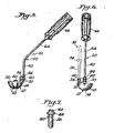
- Figure 6 is a rear elevational view of the instrument showing a drill bit in phantom outline about to enter the drill guide;
- Figure 7 is a fragmental pictorial view of the inner tip of the handle structure;
- Figure 8 is a front elevational view of an alignment rod for use with the acetabulum sizer and drill guide instrument;
- Figure 9 is a right side elevational view of the alignment rod; and
- Figure 10 is a left side elevational view of the acetabulum sizer and drill guide instrument seated within an acetabulum and with the alignment rod attached to the instrument, certain portions being broken away to show interior detail.
- Referring in more particularity to the drawing, an acetabulum sizer and
drill guide instrument 10 comprises a substantiallyhemispherical shell 12 having anoutside surface 14 that generally conforms to the outside surface of an acetabular cup prosthesis (not shown) to be fitted into a preparedacetabulum 16.Viewing ports 18 are provided inshell 12 for visual inspection of theacetabulum 16 while theshell 12 is seated therein.Viewing ports 18 may comprise a series of spaced apart slotted openings positioned aroundshell 12. A circularperipheral rim 20 onshell 12 is generally flush with the peripheral boundary of a properly sizedacetabulum 16 whenshell 12 is seated therein.Handle structure 22 is provided for manipulatingshell 12 relative toacetabulum 16.Instrument 10 may be fabricated from stainless steel by techniques known in the art, it being understood that other materials are equally suitable. -
Instrument 10 also includes specificdrill guide structure 24 for guiding adrill bit 26 into thepelvis bone 28adjacent acetabulum 16 in the formation of prosthesis anchoring holes 30. Thedrill guide structure 24 comprises a pair of spaced apart open endedbushings 32 onshell 12 close to the peripheral boundary thereof. Eachbushing 32 defines a path of travel fordrill bit 26 which is substantially perpendicular to the plane defined byperipheral rim 20 ofshell 12. - At this point, it should be pointed out that the dimensional characteristics of the particular acetabular cup prosthesis to be fitted onto the
acetabulum 16 dictate the dimensions of theinstrument 10 of the present invention. As noted above, theoutside surface 14 ofshell 12 corresponds to the outside surface of the prosthesis. Additionally, the location and specifics ofdrill guide structure 24 are dictated by the number and location of the anchoring posts on the prosthesis. These posts fit into anchoring holes 30 formed by the interaction ofdrill bit 26 and bushings 32. In essence,instrument 10 is initially used by the orthopedic surgeon to determine that preparedacetabulum 16 is properly sized; after that determination is made, theinstrument 10 serves to form anchoring holes 30 in the most desirable area ofpelvis bone 28 surroundingacetabulum 16 whereby the prosthesis is properly fitted into theacetabulum 16 when introduced. -
Bushings 32 onshell 12 are spaced 45° apart. Also, as shown best in Figure 6, the outside upper orstop surface 34 of each bushing 32 functions as a stop for limiting the depth of the holes 30 drilled intopelvis bone 28. In this regard,drill bit 26 includes an enlargedannular collar 36 fixed to the shank ofdrill bit 26, and thecollar 36 engagesstop surface 34 of bushing 32 to thereby limit the depth of the hole 30. - As shown best in Figures 6 and 7,
handle 22 includes atip end portion 38 dimensionally arranged to releasably fit within either one ofbushings 32. Eachbushing 32 has an openended slot 40, and akey 42 on the outside oftip end portion 38 slidably engages withinslot 40 whenhandle 22 is fitted into either one ofbushings 32. Moreover,tip end portion 38 includes astop 44 which limits the extent to which handle 22 is inserted into either one ofbushings 32. Bottoming out of key 42 inslot 40 also serves in limiting movement ofhandle 22 intobushing 32. Relative rotation betweenhandle 22 andshell 12 is prevented by the interaction betweenkey 42 andslot 40. - An
alignment rod 46 is used to assist in properly orienting thedrill guide structure 24 relative to acetabulum 16 and surroundingpelvis bone 28. As shown best in Figures 8-10,alignment rod 46 has afirst portion 48 for attachment to shell 12, as explained more fully below. Asecond portion 50 is releasably connected tofirst portion 48 by aconnector block 52.Second portion 50 forms an angle of 135° withfirst portion 48, and, as explained more fully below, whenalignment rod 46 is connected to shell 12,second portion 50 forms an angle of 45° with a plane defined by theperipheral rim 20 of theshell 12.First portion 48 ofalignment rod 46 includes anextension 54 with agrip 56 at the free end thereof. Both thefirst portion 48 and itsextension 54 are permanently fixed toconnector block 52, whilesecond portion 50 is releasably secured toconnector block 52. An offset 58 near the inner end offirst portion 48 provides clearance for the anatomical femur during the sizing procedure, as explained below. - As shown best in Figures 1 and 2,
shell 12 has an outwardly extendingcentral socket 60 for attachingalignment rod 46 to shell 12.Socket 60 may be integrally formed withshell 12 so that the central axis ofsocket 60 is substantially perpendicular to the plane defined byperipheral rim 20 ofshell 12. - In addition to its
tip end portion 38, handle 22 includes aproximal end half 62 having an axis substantially perpendicular to a plane defined byperipheral rim 20 ofshell 12 whenhandle 22 is fitted into eitherbushing 32. Also, adistal half 64 is connected toproximal half 62 at an angle of approximately 135°, and agrip 66 is fixed at the end ofdistal half 64. The relative orientation ofdistal half 64, key 42 and eachslot 40 is such thatdistal half 64 ofhandle 22 is angled away fromshell 12 whenhandle 22 is fitted into either ofbushings 32. This relationship provides an unobstructed view ofshell 12 during the sizing and drilling procedures. - The acetabulum sizer and
drill guide instrument 10 of the present invention is used in the following manner. After dislocation of the anatomical femoral head from its associated acetabulum, the acetabulum is prepared to receive the prosthesis by reaming thecavity 16 until it dimensionally complements the prosthesis. Throughout the reaming operation, the reaming tool is periodically removed andinstrument 10 is positioned within thecavity 16 via manipulation ofhandle 22, which may be placed in either one ofbushings 32 during this procedure. Theviewing ports 18 enable visual inspection of the acetabulum 16 while theshell 12 is seated therein. Finally, when theacetabulum 16 is believed to be properly sized, theinstrument 10 is again positioned within the cavity and theperipheral rim 20 of thehemispherical shell 12 is compared to the peripheral boundary of theacetabulum 16. Such comparison may be accomplished by sight and/or by simply running one's finger along the juncture ofperipheral rim 20 and the peripheral boundary ofacetabulum 16. When theperipheral rim 20 is generally flush with the peripheral boundary of the acetabulum 16, theacetabulum 16 is properly sized for the prosthesis to be fitted therein. - After such determination that acetabulum 16 is properly sized,
shell 12 is again seated within theacetabulum 16 and rotated relative thereto by manipulatinghandle 22. The purpose of this procedure is to locate the best purchase for anchoring holes 30. The surroundingpelvis bone 28 may be viewed along sight lines throughbushings 32 until the best proximate anchoring site is found. Relative rotation ofshell 12 and handle 22 is prevented by the abutting interaction ofslot 40 and key 42. Also, throughout the sizing procedure, handle 22 may be removed fromshell 12 which allowsshell 12 to remain unattended within theacetabulum cavity 16. - Following this procedure,
alignment rod 46 is fitted intosocket 60 onshell 12 and rotated to a position where offset 58 is opposite the anatomical femur of the patient. Both handle 22 andgrip 56 are manipulated untilsecond portion 50 ofalignment rod 46 extends laterally of the patient and is also perpendicular to the coronal or long axis 68 of the patient, as shown in Figure 10. When this alignment occurs,shell 12 is exactly positioned within a 45° lateral opening inacetabulum 16 at neutral anteversion. - The orientation of
first portion 48 and itsextension 54 ofalignment rod 46 is such thatfirst portion 48 andextension 54 form an angle of approximately 45° with the coronal axis 68 of the patient whenshell 12 is positioned within a 45° lateral opening inacetabulum 16 at neutral anteversion. Should no anteversion be required, no further alignment ofshell 12 is necessary. However, should anteversion be required,shell 12 is rotated the required amount by holdinggrip 66 androtating alignment rod 46 the required amount of anteversion while still maintaining the 45° relationship betweenfirst portion 48 and itsextension 54 relative to coronal axis 68 of the patient. In Figure 10,shell 12 is positioned at neutral anteversion, and rotation ofalignment rod 46 upwardly and out of the plane of the paper produces the desired degree of anteversion. - With
shell 12 so positioned, prosthesis anchoring holes 30 are formed inpelvis bone 28adjacent acetabulum 16.Drill bit 26 is inserted into and through eachbushing 32 ofdrill guide structure 24 and into the pelvis untilcollar 36 ondrill bit 26 engagesstop surface 34 onbushing 32. When the first hole is being formed, thetip end portion 38 ofhandle 22 is fitted within theother bushing 32 and vice versa. - Following this procedure, the acetabulum sizer and
drill guide instrument 10 is removed and the prosthesis inserted into theprepared acetabulum cavity 16. The anchoring posts on the prosthesis properly fit within drilled anchoring holes 30. Moreover, the angular orientation of the anchoring holes 30 is such that the prosthesis has the proper amount of anteversion, if desired. When bone cement, such as methyl methacrylate, is used to assist in anchoring the prosthesis within the acetabulum, the properly sized acetabulum results in a uniform distribution of cement between the exterior surface of the prosthesis and the interior surface of the acetabulum.
Claims (10)
Priority Applications (1)
| Application Number | Priority Date | Filing Date | Title |
|---|---|---|---|
| AT87100857T ATE58996T1 (en) | 1983-10-19 | 1984-10-16 | CALIBRATION DEVICE AND DRILLING TEMPLATE. |
Applications Claiming Priority (2)
| Application Number | Priority Date | Filing Date | Title |
|---|---|---|---|
| US06/543,207 US4528980A (en) | 1983-10-19 | 1983-10-19 | Acetabulum sizer and drill guide |
| US543207 | 1983-10-19 |
Related Parent Applications (1)
| Application Number | Title | Priority Date | Filing Date |
|---|---|---|---|
| EP84307085.5 Division | 1984-10-16 |
Publications (3)
| Publication Number | Publication Date |
|---|---|
| EP0229676A2 true EP0229676A2 (en) | 1987-07-22 |
| EP0229676A3 EP0229676A3 (en) | 1987-09-09 |
| EP0229676B1 EP0229676B1 (en) | 1990-12-12 |
Family
ID=24167036
Family Applications (2)
| Application Number | Title | Priority Date | Filing Date |
|---|---|---|---|
| EP87100857A Expired - Lifetime EP0229676B1 (en) | 1983-10-19 | 1984-10-16 | Acetabulum sizer and drill guide |
| EP84307085A Expired EP0140642B1 (en) | 1983-10-19 | 1984-10-16 | Acetabulum sizer and drill guide |
Family Applications After (1)
| Application Number | Title | Priority Date | Filing Date |
|---|---|---|---|
| EP84307085A Expired EP0140642B1 (en) | 1983-10-19 | 1984-10-16 | Acetabulum sizer and drill guide |
Country Status (7)
| Country | Link |
|---|---|
| US (1) | US4528980A (en) |
| EP (2) | EP0229676B1 (en) |
| JP (1) | JPS60108045A (en) |
| AT (2) | ATE58996T1 (en) |
| CA (1) | CA1235348A (en) |
| DE (2) | DE3472368D1 (en) |
| ES (1) | ES292577Y (en) |
Cited By (5)
| Publication number | Priority date | Publication date | Assignee | Title |
|---|---|---|---|---|
| FR2699068A1 (en) * | 1992-12-14 | 1994-06-17 | Laboureau Jacques Philippe | Ancillary equipment for patellofemoral prosthesis. |
| DE10200690B4 (en) * | 2002-01-10 | 2005-03-03 | Intraplant Ag | Aid for implantation of a hip joint endoprosthesis |
| EP1728479A1 (en) | 2005-06-01 | 2006-12-06 | Stryker Trauma SA | Quick-release guide for elements of a fixation system external to bone |
| WO2012154407A2 (en) | 2011-05-09 | 2012-11-15 | Smith & Nephew, Inc. | Patient specific instruments |
| WO2019057867A1 (en) * | 2017-09-22 | 2019-03-28 | Medichanical Engineering Aps | Device for radial expansion of an acetabulum measuring head |
Families Citing this family (151)
| Publication number | Priority date | Publication date | Assignee | Title |
|---|---|---|---|---|
| US4599999A (en) * | 1984-06-11 | 1986-07-15 | Synthes Ag | Drill guide for use with surgical compression plates |
| US4621637A (en) * | 1984-07-30 | 1986-11-11 | Meyer Fishbein | Surgical device for removing bone and tissue from joint members |
| US4632111A (en) * | 1985-03-21 | 1986-12-30 | Minnesota Mining And Manufacturing Company | Acetabular cup positioning apparatus |
| US4711233A (en) * | 1985-06-26 | 1987-12-08 | Brown Byron L | Method and apparatus for cementing an acetabular cup to an acetabulum |
| US4716894A (en) * | 1986-08-27 | 1988-01-05 | Zimmer, Inc. | Acetabular cup inserting instrument |
| GB2197790B (en) * | 1986-11-17 | 1991-01-16 | Jonathan Paul Beacon | Apparatus for use in accurately inserting prostheses |
| US4800873A (en) * | 1987-08-31 | 1989-01-31 | Audell Robert A | Method for setting fractures |
| EP0327509B1 (en) * | 1988-02-04 | 1991-05-22 | Protek AG | Surgical instrument for inserting acetabular cup prostheses |
| US4993410A (en) * | 1989-05-01 | 1991-02-19 | Kimsey Timothy P | Prosthetic removal device |
| US5141512A (en) * | 1989-08-28 | 1992-08-25 | Farmer Malcolm H | Alignment of hip joint sockets in hip joint replacement |
| US5004476A (en) * | 1989-10-31 | 1991-04-02 | Tulane University | Porous coated total hip replacement system |
| US5030221A (en) * | 1989-12-13 | 1991-07-09 | Buechel Frederick F | Prosthesis holding system |
| US5030219A (en) * | 1990-01-22 | 1991-07-09 | Boehringer Mannheim Corporation | Glenoid component installation tools |
| US5156626A (en) * | 1990-06-29 | 1992-10-20 | Zimmer, Inc. | Set of provisional prosthesis instrumentation |
| US5098437A (en) * | 1991-02-13 | 1992-03-24 | Pfizer Hospital Products Group, Inc. | Acetabular cup positioning insert |
| US5171243A (en) * | 1991-02-13 | 1992-12-15 | Pfizer Hospital Products Group, Inc. | Acetabular cup positioning insert |
| US5344453A (en) * | 1991-05-30 | 1994-09-06 | Boston Medical Products, Inc. | Thyroplasty implant |
| US5462548A (en) * | 1992-07-06 | 1995-10-31 | Pappas; Michael J. | Acetabular reamer |
| US5284483A (en) * | 1992-09-16 | 1994-02-08 | Zimmer, Inc. | Acetabular cup inserting instrument |
| JPH06178787A (en) * | 1992-12-14 | 1994-06-28 | Shima Yumiko | Centrum spacer with joint, intervertebral cavity measuring device and centrum spacer pattern |
| FR2705885B1 (en) * | 1993-06-01 | 1995-07-28 | Medinov Sa | Installation set for a unicompartmental knee prosthesis. |
| US5584837A (en) * | 1993-08-13 | 1996-12-17 | Petersen; Thomas D. | Acetabular cup inserter for orthopedic |
| FR2721201B1 (en) * | 1994-06-16 | 1997-01-17 | Patrick Marie Crol Labourdette | Cotyloid prosthesis, its use in order to reduce wear, creep and tilting and promote bone regrowth and ancillary instrumentation for its implementation. |
| US5474560A (en) * | 1994-09-26 | 1995-12-12 | Zimmer, Inc. | Prosthetic acetabular cup inserter |
| US5779710A (en) * | 1996-06-21 | 1998-07-14 | Matsen, Iii; Frederick A. | Joint replacement method and apparatus |
| US5951564A (en) * | 1996-12-18 | 1999-09-14 | Bristol-Myers Squibb Company | Orthopaedic positioning apparatus |
| US6152930A (en) * | 1998-10-28 | 2000-11-28 | Depuy Orthopaedics, Inc. | Acetabular cup extraction system |
| SE514561C2 (en) * | 1999-07-27 | 2001-03-12 | Bo Tillander | Straightening and compression instruments intended for use in hip replacement surgery |
| US6830570B1 (en) * | 1999-10-21 | 2004-12-14 | Sdgi Holdings, Inc. | Devices and techniques for a posterior lateral disc space approach |
| US6342057B1 (en) | 2000-04-28 | 2002-01-29 | Synthes (Usa) | Remotely aligned surgical drill guide |
| US6379364B1 (en) | 2000-04-28 | 2002-04-30 | Synthes (Usa) | Dual drill guide for a locking bone plate |
| US6673113B2 (en) | 2001-10-18 | 2004-01-06 | Spinecore, Inc. | Intervertebral spacer device having arch shaped spring elements |
| US7169182B2 (en) * | 2001-07-16 | 2007-01-30 | Spinecore, Inc. | Implanting an artificial intervertebral disc |
| US20050125064A1 (en) * | 2001-02-15 | 2005-06-09 | Spinecore, Inc. | Intervertebral spacer device |
| US7771477B2 (en) * | 2001-10-01 | 2010-08-10 | Spinecore, Inc. | Intervertebral spacer device utilizing a belleville washer having radially spaced concentric grooves |
| JP4384498B2 (en) | 2002-02-08 | 2009-12-16 | チャナ,ガーシャラン,シン | Improved surgical device and method of use |
| US20080027548A9 (en) | 2002-04-12 | 2008-01-31 | Ferree Bret A | Spacerless artificial disc replacements |
| US8038713B2 (en) * | 2002-04-23 | 2011-10-18 | Spinecore, Inc. | Two-component artificial disc replacements |
| US6706068B2 (en) | 2002-04-23 | 2004-03-16 | Bret A. Ferree | Artificial disc replacements with natural kinematics |
| EP1499248B1 (en) | 2002-04-30 | 2010-03-10 | Greatbatch Medical SA | Reamer spindle for minimally invasive joint surgery |
| US20030229352A1 (en) | 2002-06-10 | 2003-12-11 | Penenberg Brad L. | Apparatus for and method of providing a hip replacement |
| US6997928B1 (en) | 2002-06-10 | 2006-02-14 | Wright Medical Technology, Inc. | Apparatus for and method of providing a hip replacement |
| US7179297B2 (en) | 2002-09-17 | 2007-02-20 | Smith & Nephew, Inc. | Combined bipolar and unipolar trials |
| US7247158B2 (en) | 2003-02-04 | 2007-07-24 | Wright Medical Technology, Inc. | Acetabular impactor |
| US6908484B2 (en) * | 2003-03-06 | 2005-06-21 | Spinecore, Inc. | Cervical disc replacement |
| AU2004220634B2 (en) * | 2003-03-06 | 2009-09-17 | Spinecore, Inc. | Instrumentation and methods for use in implanting a cervical disc replacement device |
| US7105028B2 (en) * | 2003-10-21 | 2006-09-12 | Wright Medical Technology, Inc. | Tissue preserving and minimally invasive hip replacement surgical procedure |
| US7037310B2 (en) * | 2003-10-21 | 2006-05-02 | Wright Medical Technology Inc | Acetabular impactor |
| US7335207B1 (en) | 2003-11-26 | 2008-02-26 | Biomet Manufacturing Corp. | Minimally invasive cup impactor |
| US7488327B2 (en) | 2004-04-12 | 2009-02-10 | Synthes (U.S.A.) | Free hand drill guide |
| US8277457B1 (en) | 2004-12-09 | 2012-10-02 | Greatbatch Medical S.A. | Orthopaedic inserter using a collet mechanism |
| US20060161167A1 (en) * | 2005-01-18 | 2006-07-20 | Reese Myers | Acetabular instrument alignment guide |
| US7371260B2 (en) * | 2005-10-26 | 2008-05-13 | Biomet Sports Medicine, Inc. | Method and instrumentation for the preparation and transplantation of osteochondral allografts |
| US8506597B2 (en) * | 2011-10-25 | 2013-08-13 | Biomet Sports Medicine, Llc | Method and apparatus for interosseous membrane reconstruction |
| US8608749B2 (en) | 2006-02-27 | 2013-12-17 | Biomet Manufacturing, Llc | Patient-specific acetabular guides and associated instruments |
| US9918740B2 (en) | 2006-02-27 | 2018-03-20 | Biomet Manufacturing, Llc | Backup surgical instrument system and method |
| US9113971B2 (en) | 2006-02-27 | 2015-08-25 | Biomet Manufacturing, Llc | Femoral acetabular impingement guide |
| US8133234B2 (en) * | 2006-02-27 | 2012-03-13 | Biomet Manufacturing Corp. | Patient specific acetabular guide and method |
| US8377066B2 (en) | 2006-02-27 | 2013-02-19 | Biomet Manufacturing Corp. | Patient-specific elbow guides and associated methods |
| US8864769B2 (en) | 2006-02-27 | 2014-10-21 | Biomet Manufacturing, Llc | Alignment guides with patient-specific anchoring elements |
| US8535387B2 (en) | 2006-02-27 | 2013-09-17 | Biomet Manufacturing, Llc | Patient-specific tools and implants |
| US8608748B2 (en) | 2006-02-27 | 2013-12-17 | Biomet Manufacturing, Llc | Patient specific guides |
| US8603180B2 (en) | 2006-02-27 | 2013-12-10 | Biomet Manufacturing, Llc | Patient-specific acetabular alignment guides |
| US20150335438A1 (en) | 2006-02-27 | 2015-11-26 | Biomet Manufacturing, Llc. | Patient-specific augments |
| US8241293B2 (en) | 2006-02-27 | 2012-08-14 | Biomet Manufacturing Corp. | Patient specific high tibia osteotomy |
| US9907659B2 (en) | 2007-04-17 | 2018-03-06 | Biomet Manufacturing, Llc | Method and apparatus for manufacturing an implant |
| US8568487B2 (en) | 2006-02-27 | 2013-10-29 | Biomet Manufacturing, Llc | Patient-specific hip joint devices |
| US9345548B2 (en) | 2006-02-27 | 2016-05-24 | Biomet Manufacturing, Llc | Patient-specific pre-operative planning |
| US7967868B2 (en) | 2007-04-17 | 2011-06-28 | Biomet Manufacturing Corp. | Patient-modified implant and associated method |
| US8858561B2 (en) | 2006-06-09 | 2014-10-14 | Blomet Manufacturing, LLC | Patient-specific alignment guide |
| US8407067B2 (en) | 2007-04-17 | 2013-03-26 | Biomet Manufacturing Corp. | Method and apparatus for manufacturing an implant |
| US8092465B2 (en) | 2006-06-09 | 2012-01-10 | Biomet Manufacturing Corp. | Patient specific knee alignment guide and associated method |
| US8591516B2 (en) | 2006-02-27 | 2013-11-26 | Biomet Manufacturing, Llc | Patient-specific orthopedic instruments |
| US9289253B2 (en) | 2006-02-27 | 2016-03-22 | Biomet Manufacturing, Llc | Patient-specific shoulder guide |
| US9173661B2 (en) | 2006-02-27 | 2015-11-03 | Biomet Manufacturing, Llc | Patient specific alignment guide with cutting surface and laser indicator |
| US10278711B2 (en) | 2006-02-27 | 2019-05-07 | Biomet Manufacturing, Llc | Patient-specific femoral guide |
| US9339278B2 (en) | 2006-02-27 | 2016-05-17 | Biomet Manufacturing, Llc | Patient-specific acetabular guides and associated instruments |
| DE102007020484A1 (en) * | 2006-05-01 | 2007-12-13 | Precimed S.A. | Insertion instrument for minimally invasive joint surgery with exchangeable thread |
| US20070274905A1 (en) * | 2006-05-24 | 2007-11-29 | Water To Gas Lp | Thermal disassociation of water |
| US9795399B2 (en) | 2006-06-09 | 2017-10-24 | Biomet Manufacturing, Llc | Patient-specific knee alignment guide and associated method |
| US7670343B2 (en) * | 2006-06-14 | 2010-03-02 | Biomet Manufacturing Corp. | Method and apparatus for reaming an acetabulum |
| WO2008005941A2 (en) * | 2006-06-30 | 2008-01-10 | Hodge Biomotion Technologies, Llc | Precision acetabular machining system and resurfacing acetabular implant |
| US7998146B2 (en) * | 2007-02-12 | 2011-08-16 | Innomed, Inc. | Apparatus and method for hip cup extraction |
| EP2114262A1 (en) * | 2007-02-13 | 2009-11-11 | Orthogroup, Inc. | Drill system for acetabular cup implants |
| CN106037872B (en) | 2007-12-06 | 2020-01-07 | 史密夫和内修有限公司 | System and method for determining a mechanical axis of a femur |
| US8398650B1 (en) | 2009-01-27 | 2013-03-19 | Greatbatch Medical S.A. | Offset cup impactor with an expandable dome for double mobility implants |
| US8366719B2 (en) | 2009-03-18 | 2013-02-05 | Integrated Spinal Concepts, Inc. | Image-guided minimal-step placement of screw into bone |
| US8794977B2 (en) * | 2009-04-29 | 2014-08-05 | Lifemodeler, Inc. | Implant training system |
| US9241720B2 (en) * | 2009-07-10 | 2016-01-26 | Peter Forsell | Hip joint instrument and method |
| DE102009028503B4 (en) | 2009-08-13 | 2013-11-14 | Biomet Manufacturing Corp. | Resection template for the resection of bones, method for producing such a resection template and operation set for performing knee joint surgery |
| US8632547B2 (en) | 2010-02-26 | 2014-01-21 | Biomet Sports Medicine, Llc | Patient-specific osteotomy devices and methods |
| US9386994B2 (en) | 2010-06-11 | 2016-07-12 | Smith & Nephew, Inc. | Patient-matched instruments |
| US10245045B2 (en) | 2010-06-30 | 2019-04-02 | Smith & Nephew, Inc. | Resection instrument |
| US10206690B2 (en) | 2010-06-30 | 2019-02-19 | Smith & Nephew, Inc. | Bone and tissue marker |
| EP2603154A4 (en) * | 2010-08-13 | 2016-05-04 | Smith & Nephew Inc | Surgical guides |
| US8961528B2 (en) | 2010-08-27 | 2015-02-24 | Greatbatch Medical S.A. | Offset cup impactor with a grasping plate for double mobility implants |
| US9271744B2 (en) | 2010-09-29 | 2016-03-01 | Biomet Manufacturing, Llc | Patient-specific guide for partial acetabular socket replacement |
| EP2632349B1 (en) | 2010-10-29 | 2018-03-07 | The Cleveland Clinic Foundation | System for assisting with attachment of a stock implant to a patient tissue |
| US9968376B2 (en) | 2010-11-29 | 2018-05-15 | Biomet Manufacturing, Llc | Patient-specific orthopedic instruments |
| US8585709B2 (en) | 2011-01-17 | 2013-11-19 | Greatbatch Medical S.A. | Straight cup impactor with lever arm |
| US9119731B2 (en) | 2011-01-17 | 2015-09-01 | Greatbach Medical S.A. | Straight cup impactor |
| US9023112B2 (en) * | 2011-02-24 | 2015-05-05 | Depuy (Ireland) | Maintaining proper mechanics THA |
| US9241745B2 (en) | 2011-03-07 | 2016-01-26 | Biomet Manufacturing, Llc | Patient-specific femoral version guide |
| US8715289B2 (en) | 2011-04-15 | 2014-05-06 | Biomet Manufacturing, Llc | Patient-specific numerically controlled instrument |
| US8956364B2 (en) | 2011-04-29 | 2015-02-17 | Biomet Manufacturing, Llc | Patient-specific partial knee guides and other instruments |
| US8668700B2 (en) | 2011-04-29 | 2014-03-11 | Biomet Manufacturing, Llc | Patient-specific convertible guides |
| US8532807B2 (en) | 2011-06-06 | 2013-09-10 | Biomet Manufacturing, Llc | Pre-operative planning and manufacturing method for orthopedic procedure |
| US9084618B2 (en) | 2011-06-13 | 2015-07-21 | Biomet Manufacturing, Llc | Drill guides for confirming alignment of patient-specific alignment guides |
| JP6121406B2 (en) | 2011-06-16 | 2017-04-26 | スミス アンド ネフュー インコーポレイテッド | Surgical alignment using criteria |
| US8764760B2 (en) | 2011-07-01 | 2014-07-01 | Biomet Manufacturing, Llc | Patient-specific bone-cutting guidance instruments and methods |
| US20130001121A1 (en) | 2011-07-01 | 2013-01-03 | Biomet Manufacturing Corp. | Backup kit for a patient-specific arthroplasty kit assembly |
| US8597365B2 (en) | 2011-08-04 | 2013-12-03 | Biomet Manufacturing, Llc | Patient-specific pelvic implants for acetabular reconstruction |
| EP2561835B1 (en) | 2011-08-26 | 2016-03-16 | Greatbatch Medical SA | Straight cup impactor |
| US9295497B2 (en) | 2011-08-31 | 2016-03-29 | Biomet Manufacturing, Llc | Patient-specific sacroiliac and pedicle guides |
| US9066734B2 (en) | 2011-08-31 | 2015-06-30 | Biomet Manufacturing, Llc | Patient-specific sacroiliac guides and associated methods |
| US9028502B2 (en) | 2011-09-23 | 2015-05-12 | Greatbatch Medical S.A. | Ceramic implant holder |
| KR20130046337A (en) | 2011-10-27 | 2013-05-07 | 삼성전자주식회사 | Multi-view device and contol method thereof, display apparatus and contol method thereof, and display system |
| US9301812B2 (en) | 2011-10-27 | 2016-04-05 | Biomet Manufacturing, Llc | Methods for patient-specific shoulder arthroplasty |
| US9554910B2 (en) | 2011-10-27 | 2017-01-31 | Biomet Manufacturing, Llc | Patient-specific glenoid guide and implants |
| US9451973B2 (en) | 2011-10-27 | 2016-09-27 | Biomet Manufacturing, Llc | Patient specific glenoid guide |
| EP2770918B1 (en) | 2011-10-27 | 2017-07-19 | Biomet Manufacturing, LLC | Patient-specific glenoid guides |
| US9668745B2 (en) | 2011-12-19 | 2017-06-06 | Depuy Ireland Unlimited Company | Anatomical concentric spheres THA |
| US9237950B2 (en) | 2012-02-02 | 2016-01-19 | Biomet Manufacturing, Llc | Implant with patient-specific porous structure |
| US9801641B2 (en) | 2012-11-30 | 2017-10-31 | Ebi, Llc | Adjustable drill depth guide |
| US9060788B2 (en) | 2012-12-11 | 2015-06-23 | Biomet Manufacturing, Llc | Patient-specific acetabular guide for anterior approach |
| US9204977B2 (en) | 2012-12-11 | 2015-12-08 | Biomet Manufacturing, Llc | Patient-specific acetabular guide for anterior approach |
| US9301858B2 (en) | 2013-02-21 | 2016-04-05 | The Cleveland Clinic Foundation | Apparatus and method for aiding visualization and/or placing a landmark during a surgical procedure |
| AU2013379741B2 (en) | 2013-03-01 | 2018-08-30 | Stryker Corporation | Acetabular cup remover with indexing assembly for rotating the removal blade around the cup |
| US9839438B2 (en) | 2013-03-11 | 2017-12-12 | Biomet Manufacturing, Llc | Patient-specific glenoid guide with a reusable guide holder |
| US9579107B2 (en) | 2013-03-12 | 2017-02-28 | Biomet Manufacturing, Llc | Multi-point fit for patient specific guide |
| US9498233B2 (en) | 2013-03-13 | 2016-11-22 | Biomet Manufacturing, Llc. | Universal acetabular guide and associated hardware |
| US9826981B2 (en) | 2013-03-13 | 2017-11-28 | Biomet Manufacturing, Llc | Tangential fit of patient-specific guides |
| US9517145B2 (en) * | 2013-03-15 | 2016-12-13 | Biomet Manufacturing, Llc | Guide alignment system and method |
| US9668760B2 (en) * | 2013-08-08 | 2017-06-06 | Scott Kelley | Methods and systems for preparing the acetabulum to receive an acetabular component in a hip replacement surgical procedure |
| US20150112349A1 (en) | 2013-10-21 | 2015-04-23 | Biomet Manufacturing, Llc | Ligament Guide Registration |
| US10282488B2 (en) | 2014-04-25 | 2019-05-07 | Biomet Manufacturing, Llc | HTO guide with optional guided ACL/PCL tunnels |
| US9408616B2 (en) | 2014-05-12 | 2016-08-09 | Biomet Manufacturing, Llc | Humeral cut guide |
| US9839436B2 (en) | 2014-06-03 | 2017-12-12 | Biomet Manufacturing, Llc | Patient-specific glenoid depth control |
| US9561040B2 (en) | 2014-06-03 | 2017-02-07 | Biomet Manufacturing, Llc | Patient-specific glenoid depth control |
| US9833245B2 (en) | 2014-09-29 | 2017-12-05 | Biomet Sports Medicine, Llc | Tibial tubercule osteotomy |
| US9826994B2 (en) | 2014-09-29 | 2017-11-28 | Biomet Manufacturing, Llc | Adjustable glenoid pin insertion guide |
| US9820868B2 (en) | 2015-03-30 | 2017-11-21 | Biomet Manufacturing, Llc | Method and apparatus for a pin apparatus |
| US10226262B2 (en) | 2015-06-25 | 2019-03-12 | Biomet Manufacturing, Llc | Patient-specific humeral guide designs |
| US10568647B2 (en) | 2015-06-25 | 2020-02-25 | Biomet Manufacturing, Llc | Patient-specific humeral guide designs |
| US10722310B2 (en) | 2017-03-13 | 2020-07-28 | Zimmer Biomet CMF and Thoracic, LLC | Virtual surgery planning system and method |
| CN107440779B (en) * | 2017-07-18 | 2023-06-20 | 陈伟 | Safe angle positioner for setting ischial screws for acetabular fracture reduction |
| CN107374695B (en) * | 2017-08-22 | 2023-06-30 | 山东大学齐鲁医院(青岛) | Bone platform perforating device |
| CN110313971A (en) * | 2018-03-29 | 2019-10-11 | 林克骨科(中国)有限公司 | Guiding type angle is bored |
| US11801151B2 (en) | 2019-03-12 | 2023-10-31 | Howmedica Osteonics Corp. | Anatomic shell 2-in-1 window trial |
| USD952848S1 (en) * | 2020-11-05 | 2022-05-24 | Shukla Medical | Measurement guide for an acetabular cup extractor |
| RU204698U1 (en) * | 2021-04-01 | 2021-06-07 | Федеральное государственное бюджетное образовательное учреждение высшего образования «Казанский государственный медицинский университет» Министерства здравоохранения Российской Федерации | A device for the formation of anchor blind holes in the acetabulum |
Citations (4)
| Publication number | Priority date | Publication date | Assignee | Title |
|---|---|---|---|---|
| US3641590A (en) * | 1970-01-16 | 1972-02-15 | Arthur A Michele | Acetabular replacement prosthesis and method of assembling |
| FR2233972A1 (en) * | 1973-06-22 | 1975-01-17 | C E R A V E R | Artificial hip joint fitting equipment - has drilling jig in round cutter head for retaining boss socket |
| FR2245328A1 (en) * | 1973-10-02 | 1975-04-25 | Rosenthal Stemag Tech Kera | |
| EP0059044A2 (en) * | 1981-02-20 | 1982-09-01 | Pfizer Hospital Products Group, Inc. | Tool for use in inserting a surgical wire |
Family Cites Families (9)
| Publication number | Priority date | Publication date | Assignee | Title |
|---|---|---|---|---|
| US2725053A (en) * | 1953-10-26 | 1955-11-29 | Bambara John | Surgical nail guide |
| US3815590A (en) * | 1973-05-02 | 1974-06-11 | W Deyerle | Off-set trial prosthesis device and method for hip prosthesis surgery |
| US3859992A (en) * | 1973-06-06 | 1975-01-14 | Harlan C Amstutz | Vacuum-operated acetabular cup holder and positioner |
| US4135517A (en) * | 1977-07-21 | 1979-01-23 | Minnesota Mining And Manufacturing Company | Femoral prosthesis trial fitting device |
| US4211241A (en) * | 1978-03-03 | 1980-07-08 | Kastec Corporation | Heart valve sizing gauge |
| US4349017A (en) * | 1978-03-31 | 1982-09-14 | Sayegh Antoine Y | Orthopaedic apparatus |
| GB2086729B (en) * | 1980-11-01 | 1984-03-21 | Charnley Surgical Inventions | Trimming aid for hip joint surgery |
| US4305394A (en) * | 1980-12-22 | 1981-12-15 | Bertuch Jr Charles J | Acetabular cup positioning instrument |
| US4475549A (en) * | 1982-01-18 | 1984-10-09 | Indong Oh | Acetabular cup positioner and method |
-
1983
- 1983-10-19 US US06/543,207 patent/US4528980A/en not_active Expired - Lifetime
-
1984
- 1984-10-16 EP EP87100857A patent/EP0229676B1/en not_active Expired - Lifetime
- 1984-10-16 DE DE8484307085T patent/DE3472368D1/en not_active Expired
- 1984-10-16 AT AT87100857T patent/ATE58996T1/en not_active IP Right Cessation
- 1984-10-16 EP EP84307085A patent/EP0140642B1/en not_active Expired
- 1984-10-16 DE DE8787100857T patent/DE3483748D1/en not_active Expired - Fee Related
- 1984-10-16 AT AT84307085T patent/ATE35378T1/en active
- 1984-10-17 CA CA000465677A patent/CA1235348A/en not_active Expired
- 1984-10-19 JP JP59220336A patent/JPS60108045A/en active Granted
- 1984-10-19 ES ES1984292577U patent/ES292577Y/en not_active Expired
Patent Citations (4)
| Publication number | Priority date | Publication date | Assignee | Title |
|---|---|---|---|---|
| US3641590A (en) * | 1970-01-16 | 1972-02-15 | Arthur A Michele | Acetabular replacement prosthesis and method of assembling |
| FR2233972A1 (en) * | 1973-06-22 | 1975-01-17 | C E R A V E R | Artificial hip joint fitting equipment - has drilling jig in round cutter head for retaining boss socket |
| FR2245328A1 (en) * | 1973-10-02 | 1975-04-25 | Rosenthal Stemag Tech Kera | |
| EP0059044A2 (en) * | 1981-02-20 | 1982-09-01 | Pfizer Hospital Products Group, Inc. | Tool for use in inserting a surgical wire |
Cited By (9)
| Publication number | Priority date | Publication date | Assignee | Title |
|---|---|---|---|---|
| FR2699068A1 (en) * | 1992-12-14 | 1994-06-17 | Laboureau Jacques Philippe | Ancillary equipment for patellofemoral prosthesis. |
| WO1994013214A1 (en) * | 1992-12-14 | 1994-06-23 | Lars | Ancillary material for fitting a femoro-patellar prosthesis |
| DE10200690B4 (en) * | 2002-01-10 | 2005-03-03 | Intraplant Ag | Aid for implantation of a hip joint endoprosthesis |
| US7828806B2 (en) | 2002-01-10 | 2010-11-09 | Smith And Nephew Orthopaedics Ag | Accessory for implanting a hip endoprosthesis, and method for manipulating the same |
| EP1728479A1 (en) | 2005-06-01 | 2006-12-06 | Stryker Trauma SA | Quick-release guide for elements of a fixation system external to bone |
| US8353916B2 (en) | 2005-06-01 | 2013-01-15 | Stryker Trauma S.A. | Quick-release guide assembly for elements of or for an external fixation system |
| WO2012154407A2 (en) | 2011-05-09 | 2012-11-15 | Smith & Nephew, Inc. | Patient specific instruments |
| AU2012253956B2 (en) * | 2011-05-09 | 2016-12-15 | Smith & Nephew, Inc. | Patient specific instruments |
| WO2019057867A1 (en) * | 2017-09-22 | 2019-03-28 | Medichanical Engineering Aps | Device for radial expansion of an acetabulum measuring head |
Also Published As
| Publication number | Publication date |
|---|---|
| EP0140642A3 (en) | 1985-10-02 |
| DE3483748D1 (en) | 1991-01-24 |
| JPS60108045A (en) | 1985-06-13 |
| JPH0471548B2 (en) | 1992-11-16 |
| ATE35378T1 (en) | 1988-07-15 |
| DE3472368D1 (en) | 1988-08-04 |
| EP0140642B1 (en) | 1988-06-29 |
| ES292577Y (en) | 1987-03-01 |
| CA1235348A (en) | 1988-04-19 |
| ES292577U (en) | 1986-06-16 |
| EP0229676A3 (en) | 1987-09-09 |
| ATE58996T1 (en) | 1990-12-15 |
| US4528980A (en) | 1985-07-16 |
| EP0140642A2 (en) | 1985-05-08 |
| EP0229676B1 (en) | 1990-12-12 |
Similar Documents
| Publication | Publication Date | Title |
|---|---|---|
| EP0140642B1 (en) | Acetabulum sizer and drill guide | |
| EP0903127B1 (en) | Anatomic glenoid shoulder prosthesis together with methods and tools for implanting same | |
| AU676697B2 (en) | Orthopaedic cutting instrument and prosthetic device | |
| US5403320A (en) | Bone milling guide apparatus and method | |
| JP4204686B2 (en) | Reamer system for elliptical acetabulum | |
| EP2241293B1 (en) | Sleeve for proximal reamer | |
| EP1477120B1 (en) | Head centering jig for femoral resurfacing | |
| DeYOUNG et al. | Implantation of an uncemented total hip prosthesis technique and initial results of 100 arthroplasties | |
| US5201882A (en) | Modular hip joint prosthesis with adjustable anteversion | |
| US5002581A (en) | Modular hip joint prosthesis with adjustable anteversion | |
| EP1634551A2 (en) | Surgical tool | |
| US5135529A (en) | Instrument for implanting modular hip joint prosthesis with adjustable anteversion and method of using said instrument | |
| US5800437A (en) | Cannulated tamp and centering rod for total joint arthroplasty | |
| US20030181984A1 (en) | Method and instrumentation for patello-femoral joint replacement | |
| WO1994009730A9 (en) | Orthopaedic cutting instrument and prosthetic device | |
| US20050288676A1 (en) | Minimally invasive bone broach | |
| JPH11500036A (en) | Trial knee prosthesis and bone preparation system | |
| US5888245A (en) | Rotational alignment guide for a prosthetic hip stem implant and method of using same | |
| US3815590A (en) | Off-set trial prosthesis device and method for hip prosthesis surgery | |
| WO2014175986A2 (en) | A method and system for modular hip resurfacing |
Legal Events
| Date | Code | Title | Description |
|---|---|---|---|
| PUAI | Public reference made under article 153(3) epc to a published international application that has entered the european phase |
Free format text: ORIGINAL CODE: 0009012 |
|
| 17P | Request for examination filed |
Effective date: 19870123 |
|
| AC | Divisional application: reference to earlier application |
Ref document number: 140642 Country of ref document: EP |
|
| AK | Designated contracting states |
Kind code of ref document: A2 Designated state(s): AT CH DE FR GB IT LI SE |
|
| PUAL | Search report despatched |
Free format text: ORIGINAL CODE: 0009013 |
|
| AK | Designated contracting states |
Kind code of ref document: A3 Designated state(s): AT CH DE FR GB IT LI SE |
|
| 17Q | First examination report despatched |
Effective date: 19890522 |
|
| GRAA | (expected) grant |
Free format text: ORIGINAL CODE: 0009210 |
|
| AC | Divisional application: reference to earlier application |
Ref document number: 140642 Country of ref document: EP |
|
| AK | Designated contracting states |
Kind code of ref document: B1 Designated state(s): AT CH DE FR GB IT LI SE |
|
| REF | Corresponds to: |
Ref document number: 58996 Country of ref document: AT Date of ref document: 19901215 Kind code of ref document: T |
|
| REF | Corresponds to: |
Ref document number: 3483748 Country of ref document: DE Date of ref document: 19910124 |
|
| ET | Fr: translation filed | ||
| ITF | It: translation for a ep patent filed |
Owner name: MODIANO & ASSOCIATI S.R.L. |
|
| PLBE | No opposition filed within time limit |
Free format text: ORIGINAL CODE: 0009261 |
|
| STAA | Information on the status of an ep patent application or granted ep patent |
Free format text: STATUS: NO OPPOSITION FILED WITHIN TIME LIMIT |
|
| ITTA | It: last paid annual fee | ||
| 26N | No opposition filed | ||
| ITPR | It: changes in ownership of a european patent |
Owner name: CAMBIO RAGIONE SOCIALE;HOWMEDICA INC. |
|
| REG | Reference to a national code |
Ref country code: CH Ref legal event code: PFA Free format text: HOWMEDICA, INC. |
|
| REG | Reference to a national code |
Ref country code: FR Ref legal event code: CD |
|
| EAL | Se: european patent in force in sweden |
Ref document number: 87100857.9 |
|
| PGFP | Annual fee paid to national office [announced via postgrant information from national office to epo] |
Ref country code: DE Payment date: 19960902 Year of fee payment: 13 |
|
| PGFP | Annual fee paid to national office [announced via postgrant information from national office to epo] |
Ref country code: SE Payment date: 19960903 Year of fee payment: 13 |
|
| PGFP | Annual fee paid to national office [announced via postgrant information from national office to epo] |
Ref country code: GB Payment date: 19960904 Year of fee payment: 13 Ref country code: FR Payment date: 19960904 Year of fee payment: 13 |
|
| PGFP | Annual fee paid to national office [announced via postgrant information from national office to epo] |
Ref country code: AT Payment date: 19961007 Year of fee payment: 13 |
|
| PGFP | Annual fee paid to national office [announced via postgrant information from national office to epo] |
Ref country code: CH Payment date: 19961115 Year of fee payment: 13 |
|
| PG25 | Lapsed in a contracting state [announced via postgrant information from national office to epo] |
Ref country code: GB Free format text: LAPSE BECAUSE OF NON-PAYMENT OF DUE FEES Effective date: 19971016 Ref country code: AT Free format text: LAPSE BECAUSE OF NON-PAYMENT OF DUE FEES Effective date: 19971016 |
|
| PG25 | Lapsed in a contracting state [announced via postgrant information from national office to epo] |
Ref country code: SE Free format text: LAPSE BECAUSE OF NON-PAYMENT OF DUE FEES Effective date: 19971017 |
|
| PG25 | Lapsed in a contracting state [announced via postgrant information from national office to epo] |
Ref country code: LI Free format text: LAPSE BECAUSE OF NON-PAYMENT OF DUE FEES Effective date: 19971031 Ref country code: FR Free format text: THE PATENT HAS BEEN ANNULLED BY A DECISION OF A NATIONAL AUTHORITY Effective date: 19971031 Ref country code: CH Free format text: LAPSE BECAUSE OF NON-PAYMENT OF DUE FEES Effective date: 19971031 |
|
| GBPC | Gb: european patent ceased through non-payment of renewal fee |
Effective date: 19971016 |
|
| REG | Reference to a national code |
Ref country code: CH Ref legal event code: PL |
|
| PG25 | Lapsed in a contracting state [announced via postgrant information from national office to epo] |
Ref country code: DE Free format text: LAPSE BECAUSE OF NON-PAYMENT OF DUE FEES Effective date: 19980701 |
|
| EUG | Se: european patent has lapsed |
Ref document number: 87100857.9 |
|
| REG | Reference to a national code |
Ref country code: FR Ref legal event code: ST |