EP0227488A2 - Full waste toner container detector - Google Patents
Full waste toner container detector Download PDFInfo
- Publication number
- EP0227488A2 EP0227488A2 EP86310202A EP86310202A EP0227488A2 EP 0227488 A2 EP0227488 A2 EP 0227488A2 EP 86310202 A EP86310202 A EP 86310202A EP 86310202 A EP86310202 A EP 86310202A EP 0227488 A2 EP0227488 A2 EP 0227488A2
- Authority
- EP
- European Patent Office
- Prior art keywords
- waste toner
- container
- full
- toner container
- flexible
- Prior art date
- Legal status (The legal status is an assumption and is not a legal conclusion. Google has not performed a legal analysis and makes no representation as to the accuracy of the status listed.)
- Granted
Links
Images


Classifications
-
- G—PHYSICS
- G03—PHOTOGRAPHY; CINEMATOGRAPHY; ANALOGOUS TECHNIQUES USING WAVES OTHER THAN OPTICAL WAVES; ELECTROGRAPHY; HOLOGRAPHY
- G03G—ELECTROGRAPHY; ELECTROPHOTOGRAPHY; MAGNETOGRAPHY
- G03G21/00—Arrangements not provided for by groups G03G13/00 - G03G19/00, e.g. cleaning, elimination of residual charge
- G03G21/10—Collecting or recycling waste developer
- G03G21/12—Toner waste containers
Definitions
- the present invention relates to a detector for detecting a waste toner container filled up with waste toner collected from a photoreceptor surface.
- a number of detectors for detecting full waste toner container have been proposed. None of them, however, can detect the full waste toner container accurately.
- the object of the present invention is to provide a full waste toner container detector which comprises a flexible film member projecting into the container when the container is not filled up with waste toner and projecting outwardly from the container when it becomes full, a reflection plate provided on the outer surface of the flexible member to multiply the change of the flexible member caused by the waste toner pressure, and an optical sensor for detecting the change, thereby achieving accurate detection of full waste toner container.
- the present invention comprises a flexible film member provided on a waste toner container for storing waste toner collected from the photoreceptor surface, which member projects into the container when the container is not full and projects outwardly due to the waste toner pressure when the container is filled up with waste toner, a reflection plate mounted on the external surface of the flexible member, a light source for irradiating the reflection plate, and a sensor installed in such a position as to receive light reflected by the reflection plate when the flexible member projects outwardly from the container.
- FIG. 5 is a schematic construction drawing of a copying machine related to the present invention.
- a photoreceptor 1 is mounted, integrally with surrounding electric charger 2, cleaner unit 3, separator unit 4 and light exposure opening (slit) 5, in a housing 6, thus forming a cartridge 7.
- the cartridge 7 is detachable from the copying machine proper 8.
- the cartridge 7 can be set in the copying machine proper 8 simply by opening the front panel of the copying machine proper 8 and inserting the cartridge 7 vertical to a copy paper.
- the cartridge 7 can be dismounted by pulling it to the operator side.
- a rail guide mechanism (not shown) assists in mounting or dismounting the cartridge 7 in or from the copying machien proper 8.
- a convergent light transmitter 9 mounted over the light exposure slit 5 and a light source 10 provided to the left of the transmitter 9 constitute an optical system.
- a document on a manuscript rest 11 is scanned by a light beam from the light source 10 while the manuscript rest 11 is moving horizontally.
- Light from the light source 10 is reflected by the documents surface as the manuscript rest moves horizon tally.
- the light reflected from the document is transmitted through the convergent light transmitter 9 for projection on the photoreceptor 1.
- the photoreceptor 1 is rotating in the direction of the arrow of Fig. 5. After uniformly charged by the electric charger 2, the photoreceptor 1 is exposed to the light coming through the light exposure slit 5.
- An image is developed by a developing unit 12 and transferred onto a copy paper by a transference charger 13.
- the copy paper is fed from a copy paper cassette 14 by a paper feed roller 15 which is mounted at the bottom of the copying machine proper 8.
- the copy paper, on which the image on the photoreceptor 1 has been transferred, is separated from the photoreceptor 1 by a separator unit 4 and conveyed to fixing rollers 16 where the image is fixed onto the copy paper.
- the copy paper is discharged to a tray 17.
- the tray 17 is rotatable about a pin 18 in the direction of the arrow of Fig. 5.
- the tray 17, which is folded as shown is rotated counterclockwise around the pin 18 and set in the position virtually parallel to the copying machine proper 8.
- the developing unit 12 has two developing sections either of which is selected by rotation.
- Fig. 1 is a sectional view of the cartridge 7.
- the housing 6 comprises an upper frame 6a and a lower frame 6b which are joined by a machine screw 20.
- the rotary shaft of the photoreceptor 1, the electric charger 2, the separator unit 4 and the cleaner unit 3 are mounted integrally with the housing 6.
- the cleaner unit 3 comprises a blade 30 for scraping off the toner remaining on the photoreceptor 1 as waste toner, the waste toner container 31 and a waste toner collecting rotary plate 32 for sending the waste toner to the waste toner container 31.
- the separator unit 4 contains a separation tape 42, a separation roller 40 and a pressure roller 41.
- the separation tape 42 is extended between the points A and B of the lower frame 6b via a spring 43 so that the upper surface of the tape is made in contact with the trailing end surface of the photoreceptor 1.
- the separation roller 40 is in contact with the lower surface of the separation tape 42.
- the pressure roller 41 is forced by a spring 44 to press the separation roller 40 through the separation tape 42.
- the waste toner container 31 in the housing 6 has a recess 60 in its upper end.
- a flexible member 31a made of rubber film is provided in the recess 60.
- the flexible member 31a is of nearly cylindrical shape, comprising a thinner side wall "a" (See Fig. 4) and a thicker horizontal bottom “b” (See Fig. 4).
- a reflection plate 31b is provided on the external surface of the flexible member 31a.
- a reflector 21 is mounted to the upper part of the cartridge 7 within the copying machine so as to cover the light source 10.
- the reflector 21 has a small slit 21a through which light from the light source 10 passes in the direction of the flexible member 31a.
- To the left of the reflector 21 is provided a sensor 22 for receiving the light reflected from the reflection plate 31b.
- the position of the sensor 22 is such that it cannot receive the light reflected by the reflection plate 31b when the flexible member 31a projects into the waste toner container 31 as shown in Fig. 1, but receive the reflected light when the flexible member 31a projects outwardly from the container 31 as the container 31 is filled up with waste toner.
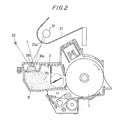
- Fig. 3 shows the appearance of the resilient member 31a and its surrounding when the flexible member 31 projects outwardly from the container 31.
- the light from the light source 10 passing through the slit 21a is reflected by the reflection plate 31b in the direction deviating to the left from the relfected light course indicated in Fig. 1, so that a part of the reflected light enters and actuates the sensor 22.
- the sensor 22 detects that the waste toner container 31 has been filled up with waste toner.
- the flexible member projects into or outwardly from the waste toner container, depending upon the pressure applied by the waste toner in the container.
- the amount of the change of the flexible member is large enough for the sensor to detect the full container very easily and accurately.
- the flexible member is provided integrally with the cartridge while the sensor and the light source are provided independently of the cartridge, the cartridge is very simple in construction and therefore produced at a low cost.
- the light source installed for irradiating the document on the copying machine is used as a light source for the detector, it is not necessary to install another light source, resulting in the simple construction of the entire copying machine.
- Another advantage of the present invention is that since the flexible member projects into the container when the container is not full, an operator can replace the cartridge without touching or causing other parts to touch the flexible member. This prevents the flexible member from being damaged or broken by an unexpected external force. Operationability in handling the cartridge is also improved by the above feature of the present invention.
- the non-contact type sensor enhances the reliability of the detector.
Abstract
Description
- The present invention relates to a detector for detecting a waste toner container filled up with waste toner collected from a photoreceptor surface.
- A number of detectors for detecting full waste toner container have been proposed. None of them, however, can detect the full waste toner container accurately.
- The object of the present invention is to provide a full waste toner container detector which comprises a flexible film member projecting into the container when the container is not filled up with waste toner and projecting outwardly from the container when it becomes full, a reflection plate provided on the outer surface of the flexible member to multiply the change of the flexible member caused by the waste toner pressure, and an optical sensor for detecting the change, thereby achieving accurate detection of full waste toner container.
- The present invention comprises a flexible film member provided on a waste toner container for storing waste toner collected from the photoreceptor surface, which member projects into the container when the container is not full and projects outwardly due to the waste toner pressure when the container is filled up with waste toner, a reflection plate mounted on the external surface of the flexible member, a light source for irradiating the reflection plate, and a sensor installed in such a position as to receive light reflected by the reflection plate when the flexible member projects outwardly from the container.
- The present invention will become more fully understood from the detailed description given hereinbelow and the accompanying drawings which are given by way of illustration only, and thus are not limitative of the present invention and wherein:
- Figs. 1 and 2 are sectional views of the cartridge in a copying machine as an embodiment of a full waste toner container detector of the present invention, with the container not filled up and with the container filled up, respectively;
- Fig. 3 shows the appearance of the flexible member and its surrounding when the container is filled up with waste toner;
- Fig. 4 is a schematic construction drawing of the copying machine.
- Fig. 5 is a schematic construction drawing of a copying machine related to the present invention. A
photoreceptor 1 is mounted, integrally with surrounding electric charger 2,cleaner unit 3,separator unit 4 and light exposure opening (slit) 5, in ahousing 6, thus forming acartridge 7. Thecartridge 7 is detachable from the copying machine proper 8. Thecartridge 7 can be set in the copying machine proper 8 simply by opening the front panel of the copying machine proper 8 and inserting thecartridge 7 vertical to a copy paper. Thecartridge 7 can be dismounted by pulling it to the operator side. A rail guide mechanism (not shown) assists in mounting or dismounting thecartridge 7 in or from the copying machien proper 8. - A
convergent light transmitter 9 mounted over thelight exposure slit 5 and alight source 10 provided to the left of thetransmitter 9 constitute an optical system. A document on amanuscript rest 11 is scanned by a light beam from thelight source 10 while themanuscript rest 11 is moving horizontally. Light from thelight source 10 is reflected by the documents surface as the manuscript rest moves horizon tally. The light reflected from the document is transmitted through theconvergent light transmitter 9 for projection on thephotoreceptor 1. Thephotoreceptor 1 is rotating in the direction of the arrow of Fig. 5. After uniformly charged by the electric charger 2, thephotoreceptor 1 is exposed to the light coming through thelight exposure slit 5. An image is developed by a developingunit 12 and transferred onto a copy paper by atransference charger 13. The copy paper is fed from acopy paper cassette 14 by apaper feed roller 15 which is mounted at the bottom of the copying machine proper 8. The copy paper, on which the image on thephotoreceptor 1 has been transferred, is separated from thephotoreceptor 1 by aseparator unit 4 and conveyed to fixingrollers 16 where the image is fixed onto the copy paper. Then, the copy paper is discharged to atray 17. Thetray 17 is rotatable about apin 18 in the direction of the arrow of Fig. 5. For copying operation, thetray 17, which is folded as shown, is rotated counterclockwise around thepin 18 and set in the position virtually parallel to the copying machine proper 8. The developingunit 12 has two developing sections either of which is selected by rotation. - Fig. 1 is a sectional view of the
cartridge 7. - The
housing 6 comprises anupper frame 6a and alower frame 6b which are joined by amachine screw 20. The rotary shaft of thephotoreceptor 1, the electric charger 2, theseparator unit 4 and thecleaner unit 3 are mounted integrally with thehousing 6. Thecleaner unit 3 comprises ablade 30 for scraping off the toner remaining on thephotoreceptor 1 as waste toner, thewaste toner container 31 and a waste toner collectingrotary plate 32 for sending the waste toner to thewaste toner container 31. Theseparator unit 4 contains aseparation tape 42, aseparation roller 40 and a pressure roller 41. Theseparation tape 42 is extended between the points A and B of thelower frame 6b via aspring 43 so that the upper surface of the tape is made in contact with the trailing end surface of thephotoreceptor 1. Theseparation roller 40 is in contact with the lower surface of theseparation tape 42. The pressure roller 41 is forced by aspring 44 to press theseparation roller 40 through theseparation tape 42. - The
waste toner container 31 in thehousing 6 has arecess 60 in its upper end. Aflexible member 31a made of rubber film is provided in therecess 60. Theflexible member 31a is of nearly cylindrical shape, comprising a thinner side wall "a" (See Fig. 4) and a thicker horizontal bottom "b" (See Fig. 4). Areflection plate 31b is provided on the external surface of theflexible member 31a. - A
reflector 21 is mounted to the upper part of thecartridge 7 within the copying machine so as to cover thelight source 10. Thereflector 21 has asmall slit 21a through which light from thelight source 10 passes in the direction of theflexible member 31a. To the left of thereflector 21 is provided asensor 22 for receiving the light reflected from thereflection plate 31b. The position of thesensor 22 is such that it cannot receive the light reflected by thereflection plate 31b when theflexible member 31a projects into thewaste toner container 31 as shown in Fig. 1, but receive the reflected light when theflexible member 31a projects outwardly from thecontainer 31 as thecontainer 31 is filled up with waste toner. - Fig. 3 shows the appearance of the
resilient member 31a and its surrounding when theflexible member 31 projects outwardly from thecontainer 31. - When the
container 31 is not full, theflexible member 31a projects into thecontainer 31. In this state, if the light coming through theslit 21a in thereflector 21 is reflected by thereflection plate 31b on theflexible member 31a, it does not enter the sensor. Waste toner in thecontainer 31 gradually increases. When it reaches a certain level, the pressure of the waste toner against the horizontal bottom "b" of theflexible member 31a exceeds the force of the side wall "a" which makes theresilient member 31a project into the container. Then, due to the waste toner pressure, themember 31a projects outwardly from thecontainer 31 as shown in Fig. 2. In this state, the light from thelight source 10 passing through theslit 21a is reflected by thereflection plate 31b in the direction deviating to the left from the relfected light course indicated in Fig. 1, so that a part of the reflected light enters and actuates thesensor 22. Thus, thesensor 22 detects that thewaste toner container 31 has been filled up with waste toner. - According to the present invention, as described above, the flexible member projects into or outwardly from the waste toner container, depending upon the pressure applied by the waste toner in the container. The amount of the change of the flexible member is large enough for the sensor to detect the full container very easily and accurately. Furthermore, since the flexible member is provided integrally with the cartridge while the sensor and the light source are provided independently of the cartridge, the cartridge is very simple in construction and therefore produced at a low cost. In addition, since the light source installed for irradiating the document on the copying machine is used as a light source for the detector, it is not necessary to install another light source, resulting in the simple construction of the entire copying machine. Another advantage of the present invention is that since the flexible member projects into the container when the container is not full, an operator can replace the cartridge without touching or causing other parts to touch the flexible member. This prevents the flexible member from being damaged or broken by an unexpected external force. Operationability in handling the cartridge is also improved by the above feature of the present invention. The non-contact type sensor enhances the reliability of the detector.
- While only certain embodiments of the present invention have been described, it will be apparent to those skilled in the art that various changes and modifications may be made therein without departing from the spirit and scope of the present invention as claimed.
- There are described above novel features which the skilled man will appreciate give rise to advantages. These are each independent aspects of the invention to be covered by the present application, irrespective of whether or not they are included within the scope of the following claims:
Claims (8)
flexible film means provided on said waste toner container; and
sensor means for sensing the expansion of said flexible film means on the condition that the waste toner container is full of the waste toner particles.
a waste toner container for storing waste toner particles collected from photoreceptor means;
a flexible film means which projects into said container when said container is not filled up with the waste toner particles and projects outwardly from said container due to the waste toner pressure when said container is full of the waste toner particles;
a reflection plate mounted on the external surface of said flexible means;
a light source for irradiating said reflection plate;
and a sensor means provided in such a position as to receive the light reflected by said reflection plate when said flexible means projects outwardly from said container.
Applications Claiming Priority (2)
| Application Number | Priority Date | Filing Date | Title |
|---|---|---|---|
| JP60297307A JPS62156685A (en) | 1985-12-27 | 1985-12-27 | Detector for fullness of waste toner |
| JP297307/85 | 1985-12-27 |
Publications (3)
| Publication Number | Publication Date |
|---|---|
| EP0227488A2 true EP0227488A2 (en) | 1987-07-01 |
| EP0227488A3 EP0227488A3 (en) | 1987-08-26 |
| EP0227488B1 EP0227488B1 (en) | 1991-11-13 |
Family
ID=17844815
Family Applications (1)
| Application Number | Title | Priority Date | Filing Date |
|---|---|---|---|
| EP86310202A Expired - Lifetime EP0227488B1 (en) | 1985-12-27 | 1986-12-29 | Full waste toner container detector |
Country Status (5)
| Country | Link |
|---|---|
| US (1) | US4761674A (en) |
| EP (1) | EP0227488B1 (en) |
| JP (1) | JPS62156685A (en) |
| CN (1) | CN1008775B (en) |
| DE (1) | DE3682492D1 (en) |
Cited By (3)
| Publication number | Priority date | Publication date | Assignee | Title |
|---|---|---|---|---|
| DE3909512A1 (en) * | 1988-03-22 | 1989-10-05 | Toshiba Kk | IMAGE GENERATING DEVICE WITH DEVICE FOR DETERMINING THE QUANTITY OF REMAINING DEVELOPERS AND METHOD FOR THIS |
| GB2218378A (en) * | 1988-04-15 | 1989-11-15 | Fuji Xerox Co Ltd | Assessing life-time of consumable parts |
| EP0827047A2 (en) * | 1996-08-29 | 1998-03-04 | Canon Kabushiki Kaisha | Cleaning frame, cleaning device, process cartridge and electrophotographic image forming apparatus |
Families Citing this family (11)
| Publication number | Priority date | Publication date | Assignee | Title |
|---|---|---|---|---|
| JP2644209B2 (en) * | 1995-04-20 | 1997-08-25 | 日本電気データ機器株式会社 | Cleaning equipment |
| US6505009B2 (en) * | 2001-06-05 | 2003-01-07 | Hewlett-Packard Company | Waste toner detection systems and methods for determining the volume of waste toner in a printer cartridge |
| US6731885B2 (en) * | 2001-06-29 | 2004-05-04 | Heidelberger Druckmaschinen Ag | Capacitive probe toner level detector assembly |
| JP2004102137A (en) * | 2002-09-12 | 2004-04-02 | Ricoh Co Ltd | Waste toner collecting apparatus and image forming apparatus |
| KR101305980B1 (en) * | 2007-01-26 | 2013-09-12 | 삼성전자주식회사 | Image forming apparatus |
| JP2011197089A (en) * | 2010-03-17 | 2011-10-06 | Kyocera Mita Corp | Remaining toner sensor and toner storage container with the same |
| JP5145370B2 (en) * | 2010-03-30 | 2013-02-13 | 京セラドキュメントソリューションズ株式会社 | Image forming apparatus |
| JP2011253173A (en) * | 2010-05-07 | 2011-12-15 | Ricoh Co Ltd | Process unit and image forming apparatus |
| TWI468881B (en) | 2012-12-25 | 2015-01-11 | Avision Inc | Device for detecting state of waste toner container and image forming apparatus using such device |
| JP2016045353A (en) * | 2014-08-22 | 2016-04-04 | カシオ計算機株式会社 | Waste toner recovery container and image forming apparatus using the same |
| JP2021196423A (en) * | 2020-06-10 | 2021-12-27 | シャープ株式会社 | Accommodated article detection device, image forming apparatus, and accommodated article detection method |
Citations (5)
| Publication number | Priority date | Publication date | Assignee | Title |
|---|---|---|---|---|
| GB1318632A (en) * | 1969-06-26 | 1973-05-31 | Ralet C | Method of and apparatus for the automatic supervision of liquid limits in closed tanks |
| GB2106835A (en) * | 1981-09-25 | 1983-04-20 | Ricoh Kk | Toner collection device |
| US4412736A (en) * | 1980-07-24 | 1983-11-01 | Ricoh Company, Ltd. | Collection of suspended toner particles |
| GB2152435A (en) * | 1981-08-19 | 1985-08-07 | Ricoh Kk | Toner collecting apparatus |
| EP0220915A1 (en) * | 1985-10-21 | 1987-05-06 | Rank Xerox Limited | Toner recovery device |
Family Cites Families (4)
| Publication number | Priority date | Publication date | Assignee | Title |
|---|---|---|---|---|
| DE2436301A1 (en) * | 1974-07-27 | 1976-02-12 | Agfa Gevaert Ag | ELECTROSTATIC COPY DEVICE |
| JPS56165178A (en) * | 1980-05-26 | 1981-12-18 | Toshiba Corp | Cleaning device for copying machine |
| JPH0766226B2 (en) * | 1984-02-09 | 1995-07-19 | 株式会社リコー | Toner collection device for image forming apparatus |
| JPS60200277A (en) * | 1984-03-23 | 1985-10-09 | Ricoh Co Ltd | Toner recovering device |
-
1985
- 1985-12-27 JP JP60297307A patent/JPS62156685A/en active Pending
-
1986
- 1986-12-23 US US06/945,520 patent/US4761674A/en not_active Expired - Lifetime
- 1986-12-24 CN CN86108832A patent/CN1008775B/en not_active Expired
- 1986-12-29 EP EP86310202A patent/EP0227488B1/en not_active Expired - Lifetime
- 1986-12-29 DE DE8686310202T patent/DE3682492D1/en not_active Expired - Lifetime
Patent Citations (5)
| Publication number | Priority date | Publication date | Assignee | Title |
|---|---|---|---|---|
| GB1318632A (en) * | 1969-06-26 | 1973-05-31 | Ralet C | Method of and apparatus for the automatic supervision of liquid limits in closed tanks |
| US4412736A (en) * | 1980-07-24 | 1983-11-01 | Ricoh Company, Ltd. | Collection of suspended toner particles |
| GB2152435A (en) * | 1981-08-19 | 1985-08-07 | Ricoh Kk | Toner collecting apparatus |
| GB2106835A (en) * | 1981-09-25 | 1983-04-20 | Ricoh Kk | Toner collection device |
| EP0220915A1 (en) * | 1985-10-21 | 1987-05-06 | Rank Xerox Limited | Toner recovery device |
Non-Patent Citations (1)
| Title |
|---|
| XEROX DISCLOSURE JOURNAL, vol. 8, no. 5, September/October 1983 CARROLL "Flexible Cleaner Seal" page 431, fig. * Page 431, line 7 * * |
Cited By (8)
| Publication number | Priority date | Publication date | Assignee | Title |
|---|---|---|---|---|
| DE3909512A1 (en) * | 1988-03-22 | 1989-10-05 | Toshiba Kk | IMAGE GENERATING DEVICE WITH DEVICE FOR DETERMINING THE QUANTITY OF REMAINING DEVELOPERS AND METHOD FOR THIS |
| US4982230A (en) * | 1988-03-22 | 1991-01-01 | Kabushiki Kaisha Toshiba | Image forming apparatus with means for detecting excess developer |
| GB2218378A (en) * | 1988-04-15 | 1989-11-15 | Fuji Xerox Co Ltd | Assessing life-time of consumable parts |
| US5021828A (en) * | 1988-04-15 | 1991-06-04 | Fuji Xerox Co., Ltd. | Copying apparatus having a consumable part |
| GB2218378B (en) * | 1988-04-15 | 1992-10-14 | Fuji Xerox Co Ltd | An apparatus for storing information on paper and consumable part thereof. |
| EP0827047A2 (en) * | 1996-08-29 | 1998-03-04 | Canon Kabushiki Kaisha | Cleaning frame, cleaning device, process cartridge and electrophotographic image forming apparatus |
| EP0827047A3 (en) * | 1996-08-29 | 1998-03-18 | Canon Kabushiki Kaisha | Cleaning frame, cleaning device, process cartridge and electrophotographic image forming apparatus |
| US6055406A (en) * | 1996-08-29 | 2000-04-25 | Canon Kabushiki Kaisha | Cleaning frame, cleaning device, process cartridge and electrophotographic image forming apparatus with segregated waste toner container |
Also Published As
| Publication number | Publication date |
|---|---|
| US4761674A (en) | 1988-08-02 |
| DE3682492D1 (en) | 1991-12-19 |
| EP0227488B1 (en) | 1991-11-13 |
| CN86108832A (en) | 1987-07-01 |
| JPS62156685A (en) | 1987-07-11 |
| CN1008775B (en) | 1990-07-11 |
| EP0227488A3 (en) | 1987-08-26 |
Similar Documents
| Publication | Publication Date | Title |
|---|---|---|
| EP0227488A2 (en) | Full waste toner container detector | |
| US5465619A (en) | Capacitive sensor | |
| US4711561A (en) | Toner recovery device | |
| JP2593315Y2 (en) | Developing device | |
| US7107002B2 (en) | Toner collection apparatus | |
| US4630653A (en) | Waste toner collecting apparatus | |
| EP0230791B1 (en) | Full waste toner container detector | |
| JP5145370B2 (en) | Image forming apparatus | |
| US4174902A (en) | Detection of developer powder amount contained in a developer reservoir | |
| EP2703895B1 (en) | Sheet stacking device and image forming apparatus provided with same | |
| JP2851365B2 (en) | Storage container detector | |
| EP0604191A1 (en) | Developing device and image forming apparatus | |
| JP2535839B2 (en) | Recovery toner full detection device | |
| JP2820695B2 (en) | Process cartridge | |
| JPH0766226B2 (en) | Toner collection device for image forming apparatus | |
| US20230185215A1 (en) | Image forming apparatus | |
| JP2742435B2 (en) | Cleaning unit | |
| JPH0546050Y2 (en) | ||
| JP2002372901A (en) | Image forming device | |
| JPH02762Y2 (en) | ||
| KR970003823Y1 (en) | Paper cassette of the apparatus using electro phtographic process | |
| JPH0727486Y2 (en) | Toner collection structure of image forming device | |
| JPS61114278A (en) | Accumulation detector of image forming material | |
| JPS63141089A (en) | Collected toner capacity detector | |
| JPH0710369Y2 (en) | Recovery toner full detection device |
Legal Events
| Date | Code | Title | Description |
|---|---|---|---|
| PUAI | Public reference made under article 153(3) epc to a published international application that has entered the european phase |
Free format text: ORIGINAL CODE: 0009012 |
|
| AK | Designated contracting states |
Kind code of ref document: A2 Designated state(s): DE FR GB |
|
| PUAL | Search report despatched |
Free format text: ORIGINAL CODE: 0009013 |
|
| AK | Designated contracting states |
Kind code of ref document: A3 Designated state(s): DE FR GB |
|
| 17P | Request for examination filed |
Effective date: 19880204 |
|
| 17Q | First examination report despatched |
Effective date: 19890908 |
|
| GRAA | (expected) grant |
Free format text: ORIGINAL CODE: 0009210 |
|
| AK | Designated contracting states |
Kind code of ref document: B1 Designated state(s): DE FR GB |
|
| REF | Corresponds to: |
Ref document number: 3682492 Country of ref document: DE Date of ref document: 19911219 |
|
| ET | Fr: translation filed | ||
| PLBE | No opposition filed within time limit |
Free format text: ORIGINAL CODE: 0009261 |
|
| STAA | Information on the status of an ep patent application or granted ep patent |
Free format text: STATUS: NO OPPOSITION FILED WITHIN TIME LIMIT |
|
| 26N | No opposition filed | ||
| REG | Reference to a national code |
Ref country code: GB Ref legal event code: IF02 |
|
| PGFP | Annual fee paid to national office [announced via postgrant information from national office to epo] |
Ref country code: FR Payment date: 20051208 Year of fee payment: 20 |
|
| PGFP | Annual fee paid to national office [announced via postgrant information from national office to epo] |
Ref country code: DE Payment date: 20051222 Year of fee payment: 20 |
|
| PGFP | Annual fee paid to national office [announced via postgrant information from national office to epo] |
Ref country code: GB Payment date: 20051228 Year of fee payment: 20 |
|
| PG25 | Lapsed in a contracting state [announced via postgrant information from national office to epo] |
Ref country code: GB Free format text: LAPSE BECAUSE OF EXPIRATION OF PROTECTION Effective date: 20061228 |
|
| REG | Reference to a national code |
Ref country code: GB Ref legal event code: PE20 |