EP0226390A2 - Shorted microstrip antenna - Google Patents
Shorted microstrip antenna Download PDFInfo
- Publication number
- EP0226390A2 EP0226390A2 EP86309412A EP86309412A EP0226390A2 EP 0226390 A2 EP0226390 A2 EP 0226390A2 EP 86309412 A EP86309412 A EP 86309412A EP 86309412 A EP86309412 A EP 86309412A EP 0226390 A2 EP0226390 A2 EP 0226390A2
- Authority
- EP
- European Patent Office
- Prior art keywords
- conductive sheet
- smsa
- grounding
- radiating
- grounding conductive
- Prior art date
- Legal status (The legal status is an assumption and is not a legal conclusion. Google has not performed a legal analysis and makes no representation as to the accuracy of the status listed.)
- Granted
Links
- 238000010295 mobile communication Methods 0.000 abstract description 4
- 239000004020 conductor Substances 0.000 description 2
- 239000003989 dielectric material Substances 0.000 description 2
- 230000004048 modification Effects 0.000 description 2
- 238000012986 modification Methods 0.000 description 2
- 239000007787 solid Substances 0.000 description 2
- 238000010276 construction Methods 0.000 description 1
- 230000000694 effects Effects 0.000 description 1
Images


Classifications
-
- H—ELECTRICITY
- H01—ELECTRIC ELEMENTS
- H01Q—ANTENNAS, i.e. RADIO AERIALS
- H01Q9/00—Electrically-short antennas having dimensions not more than twice the operating wavelength and consisting of conductive active radiating elements
- H01Q9/04—Resonant antennas
- H01Q9/0407—Substantially flat resonant element parallel to ground plane, e.g. patch antenna
- H01Q9/0421—Substantially flat resonant element parallel to ground plane, e.g. patch antenna with a shorting wall or a shorting pin at one end of the element
-
- H—ELECTRICITY
- H01—ELECTRIC ELEMENTS
- H01Q—ANTENNAS, i.e. RADIO AERIALS
- H01Q5/00—Arrangements for simultaneous operation of antennas on two or more different wavebands, e.g. dual-band or multi-band arrangements
- H01Q5/30—Arrangements for providing operation on different wavebands
- H01Q5/378—Combination of fed elements with parasitic elements
-
- H—ELECTRICITY
- H01—ELECTRIC ELEMENTS
- H01Q—ANTENNAS, i.e. RADIO AERIALS
- H01Q9/00—Electrically-short antennas having dimensions not more than twice the operating wavelength and consisting of conductive active radiating elements
- H01Q9/04—Resonant antennas
-
- H—ELECTRICITY
- H01—ELECTRIC ELEMENTS
- H01Q—ANTENNAS, i.e. RADIO AERIALS
- H01Q9/00—Electrically-short antennas having dimensions not more than twice the operating wavelength and consisting of conductive active radiating elements
- H01Q9/04—Resonant antennas
- H01Q9/0407—Substantially flat resonant element parallel to ground plane, e.g. patch antenna
- H01Q9/0414—Substantially flat resonant element parallel to ground plane, e.g. patch antenna in a stacked or folded configuration
Landscapes
- Waveguide Aerials (AREA)
Abstract
Description
- The present invention relates to a low and broad bandwidth shorted microstrip antenna which is shorted at one side thereof and may be mounted on a mobile body in a mobile communication system and provided with improved beam tilting and impedance matching characteristics.
- A shorted microwave strip antenna (SMSA) is a half-sized version of an ordinary patch antenna and provided with a miniature, light weight and low height construction. Due to such advantages, an SMSA is suitable for use as an antenna which is mounted on a mobile body in a mobile communication system. Generally, an SMSA includes a grounding conductive sheet on which a feed connector is mounted, a radiating conductive sheet which faces the grounding conductive sheet with the intermediary of air or like dielectric material, and a connecting conductive sheet positioned at the shorted end of those two conductive sheets perpendicular to the surfaces of the latter in order to connect them together.
- In the above-described type of SMSA, assume an X and a Y axes in a general plane of the emitting and the grounding conductive sheets (the Y axis extending along the general plane of the connecting conductive sheet), and a Z axis in the general plane of the connecting conductive sheet which is perpendicular to the X and Y axes. Then, emission occurs in the SMSA due to a wave source which is developed in the vicinity of a particular side of the radiating conductive sheet which is parallel to the Y axis and not shorted. If the size of the grounding conductive sheet is infinite, the SMSA is non-directional in the X-Z plane on condition that Z is greater than zero; if it is finite, the SMSA obtains the maximum directivity in the vicinity of the Z axis. When the radiating conductive sheet is positioned at, for example, substantially the center of the grounding conductive sheet, the directivity is such that the maximum emission direction is tilted from the Z direction, resulting in a decrease in the gain in the Z direction. This is accounted for by the fact that the wave source of the SMSA is not located at the center of the grounding conductive sheet. A prior art implementation to eliminate such beam tilts consists in dimensioning the grounding conductive sheet substantially twice as long as the radiating conductive sheet in the X direction. This kind of scheme, however, prevents the SMSA from being reduced in size noticeably, compared to an ordinary microstrip antenna (MSA). It therefore often occurs that it is difficult for an SMSA to be installed in a mobile body such as an automotive vehicle.
- Further, as regards an SMSA having a relatively small connecting conductive sheet, current is allowed to flow into the jacket of a cable which is joined to feed connector. This would render the impedance matching characteristic of the antenna unstable while disturbing the directivity.
- It is therefore an object of the present invention to provide an SMSA which is small in size and stable in directivity.
- It is another object of the present invention to provide an SMSA which has improved beam tilt and impedance match characteristics.
- It is another object of the present invention to provide a generally improved SMSA.
- A microstrip antenna shorted at one side thereof of the present invention comprises a generally rectangular radiating conductive sheet for supplying power to be radiated, a first grounding conductive sheet located to face and parallel to the radiating conductive sheet, a generally rectangular second grounding conductive sheet located at one side of and perpendicular to the first grounding conductive sheet and connected to the radiating conductive sheet, and a third grounding conductive sheet located to face and parallel to the second grounding conductive sheet and provided at one side of and perpendicular to the first grounding conductive sheet which opposes the one side.
- The above and other objects, features and advantages of the present invention will become more apparent from the following detailed description taken with the accompanying drawings.
-
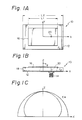
- Figs. 1A and 1B are a plan view and a side elevation, respectively, of a prior art ordinary MSA;
- Fig. 1C is a chart explanatory of the directivity of the MSA as shown in Figs. 1A and 1B;
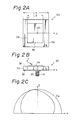
- Figs.. 2A and 2B are a schematic plan view and a side elevation, respectively, of a prior art SMSA;
- Fig. 2C is a chart similar to Fig. 1, showing the directivity of the MSA of Figs. 2A and 2B;
- Fig. 3A is a perspective view of an SMSA embodying the present invention;
- Fig. 3B is a side elevation of the SMSA as shown in Fig. 3A;
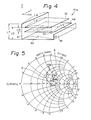
- Fig. 4 is a perspective view of another embodiment of the present invention;
- Fig. 5 is a Smith chart comparing the embodiment of Figs. 3A and 3B and that of Fig. 4 in terms of values of impedance characteristic actually measured;
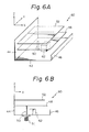
- Figs. 6A and 6B are a perspective view and a side elevation, respectively, of still another embodiment of the present invention;
- Fig. 7 is a plot comparing the embodiment of Fig. 4 and that of Figs. 6A and 6B in terms of a reflection loss characteristic;
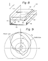
- Fig. 8 is a perspective view of a modification to the embodiment of Figs. 6A and 6B; and
- Fig. 9 is a chart showing the directivity of the SMSA of Fig. 8 together with that of the prior art SMSA for comparison.
- To facilitate an understanding of the present invention, a brief reference will be made to a prior art MSA and a prior art SMSA, as shown in Figs. 1A, 1B and 2.
- Referring to Figs. 1A and 1B, a prior art ordinary MSA 10 includes a grounding
conductive sheet 12 on which afeed connector 14 is mounted, and a radiatingconductive sheet 16 located to face thesheet 12 with the intermediary of air or likedielectric material 18. Thereference numeral 20 designates a feed pin. Assuming that the length of theconductive sheet 16 along an X axis is L₁, it is expressed as L₁ = λo/2, where λo is the free space wavelength at a frequency used and εγ, the specific relative dielectric constant of the dielectric 18. The
conductive sheet 12 is assumed to have a length L₂ in the X direction. In this type of MSA 10, emission is developed by a radiating source which is produced in the vicinity of two sides of theconductive plate 16 which are parallel to a Y axis. Eventually, the emission is such that the maximum emission direction occurs along a Z axis. - Figs. 2A and 2B show a
prior art SMSA 30 consisting of a groundingconductive sheet 32 carrying thefeed connector 14 therewith, a radiatingconductive sheet 34 located to face thesheet 32 with a intermediary of air or likeconductive material 36, and a connectingconductive sheet 38 located at the shorted end of thesheets conductive sheet 34 in the X direction is L₃, it is produced by L₃ = λo4where λo is the free space wavelength at a frequency used and εγ, the specific relative dielectric constant of the dielectric 36. The length of the
conductive sheet 32 in the X direction is assumed to be L₄. It will be understood that the length of theSMSA 30 is half the MSA 10 in terms of the length of the radiating conductive sheet, allowing the entire antenna to have considerably small dimensions. Such an antenna is desirably applicable to a mobile body of a mobile communication system. - In the
SMSA 30, emmission occurs due to a radiating source which is developed in the vicinity of that side of the radiatingconductive sheet 34 which is parallel to the Y axis and not shorted. If the size of the groundingconductive sheet 32 is infinite, theSMSA 30 is non-directional in the X-Z plane on condition that Z is greater than zero; if it is finite, theSMSA 30 obtains the maximum directivity in the vicinity of the Z axis. When the radiatingconductive sheet 34 is positioned at, for example, substantially the center of the groundingconductive sheet 32, the directivity is such that, as shown in Fig. 2C, the maximum emission direction is tilted from the Z direction, resulting in a decrease in the gain in the Z direction. This is accounted for by the fact that the wave source of theSMSA 30 is not located at the center of the groundingconductive sheet 32. A prior art implementation to eliminate such beam tilts consists in dimensioning the groundingconductive sheet 32 to Figs. 2A and 2B substantially twice as long as the radiatingconductive plate 34 in the X direction, i. e. L₄≈2 x L₃. - As previously discussed, the problem with the
prior art SMSA 30 is that the radiatingconductive plate 34 inclusive of the grounding conductive sheet is not noticeably smaller than that of theMSA 10 of Figs. 1A and 1B, although halved in size. Such often makes it difficult for the antenna to be built in an automotive vehicle and other mobile bodies. - Referring now to Figs. 3a and 3B, an SMSA embodying the present invention is shown and generally designated by the
reference numeral 40. As shown, theSMSA 40 comprises a first groundingconductive sheet 42, a second and a third groundingconductive sheets conductive sheet 42 perpendicular thereto, a radiatingconductive sheet 48 connected to theconductive sheet 44, afeed pin 50, and afeed connector 51. The second groundingconductive sheet 44 bifunctions as a connecting conductive sheet which connects the first groundingconductive sheet 42 and the radiatingconductive sheet 48 to each other. TheSMSA 40 shows the maximum directivity in a Z direction if the dimensions of the second and third groundingconductive sheets SMSA 40 which uses the second and third grounding conductive plates is greater than theprior art SMSA 30 with respect to the area of the entire grounding conductive plate. This allows a minimum of current to flow into the jacket of a feed cable which is connected to thefeed connector 51, thereby freeing the impedance and directivity from substantial influence of the feed cable. - As described above, in accordance with this particular embodiment, a miniature antenna with a minimum of beam tilt in the Z direction is attained by virtue of a second and a third grounding conductive sheets which are located at both ends of and perpendicular to a first grounding conductive sheet, which faces a radiating conductive sheet.
- Further, the antenna of this embodiment reduces current which flows into the jacket of a feed cable, compared to a prior art SMSA, whereby the impedance characteristic and the directivity are little susceptible to the influence of the feed cable and, therefore, stable operation is insured.
- Meanwhile, as shown in Fig. 4, an SMSA 40a which is provided with a
passive element 52 is broader in bandwidth than theSMSA 40 of Figs. 3A and 3B which lacks it. Specifically, the SMSA 40a is provided with a several times broader bandwidth than theSMSA 40 by adequately selecting the dimensions of thepassive element 52, the distance between thepassive element 52 and the radiatingconductive sheet 48, and the distance between thepassive element 52 and the groundingconductive sheet 42. - Referring to Fig. 5, the SMSA 40a having the
passive element 52 located close to the radiatingconductive sheet 48 as shown in Fig. 4 and theSMSA 40 without a passive element as shown in Figs. 3A and 3B are compared in terms of impedance values which were measured actually. In Fig. 5, a curve A is representative of the impedance characteristic of the SMSA 40a and a curve B, that of theSMSA 40. The curves A and B were attained by setting up a center frequency f₀ of 900 MHz. Further, assuming that the lengths of the SMSA 40a are L₅ to L₁₃ as indicated in Fig. 4, then L₅ = 92 mm, L₆ = 16 mm, L₇ = 50 mm, L₈ = 105 mm, L₉ = 85 mm, L₁₀ = 76 mm, L₁₁ = 67 mm, L₁₂ = 28 mm, and L₁₃ = 8 mm. - As described above, an SMSA with a passive element achieves a comparatively constant impedance characteristic by virtue of the effect of the passive element. However, the impedance of such an SMSA involves a part which is derived from a reactance and cannot be desirably matched to a 50-ohm system. Another drawback with this antenna is that the matching situation cannot be improved even if the feed position is changed.
- Referring to Figs. 6A and 6B, another embodiment of the present invention is shown which is provided with an improved impedance matching characteristic. In Figs. 6A and 6B, the same or similar structural elements as those shown in Fig. 4 are designated by like reference numerals. As shown, the
SMSA 60 comprises aconductive stub 62 in addition to the groundingconductive sheet 42, radiatingconductive sheet 48,passive element 52, connectingconductor 44, and feedpin 50. TheSMSA 60 can serve as a broad bandwidth antenna which well matches itself to a 50-ohm system, only if the dimensions and position of theconductive stub 62 is selected adequately. - Fig. 7 shows a reflection loss characteristic of the
SMSA 60 of Figs. 6A and 6B as represented by a solid curve and that of the SMSA 40a of Fig. 4 with a passive element as represented by a dotted curve. The solid and the dotted curves were attained with the same center frequency and the same dimensions as those previously described. As shown, hardly any power reflection less than -14 dB (VSWR = 1.5) is attained by the SMSA 40a. In contrast, theSMSA 60 of this embodiment maintains power reflection which is less than -14 dB over a very broad bandwidth, i.e. 16 %. Thus, the embodiment of Figs. 6A and 6B realizes an antenna which shows good matching to a 50-ohm system. Specifically, because theconductive stub 62 serves as an impedance compensating element which shows a constant reactance characteristic over a broad bandwidth, that part of the impedance which is derived from reactance can be compensated for without disturbing the constant impedance characteristic which is ensured by thepassive element 52. - It is to be noted that in although the
conductive stub 62 is shown as having a rectangular parallelepiped configuration, it may be provided with any other configuration such as a cylindrical one without affecting the characteristic. - As described above, this particular embodiment provides an SMSA with a passive element is provided with a conductive stub on a grounding conductive sheet which faces a radiating conductive sheet, so that its matching with a feed line of an SMSA with a passing element which shows a constant impedance is improved. The SMSA, therefore, functions as a broad bandwidth antenna having a physically low structure.
- Referring to Fig. 8, a modified embodiment of the
SMSA 60 of Figs. 6A and 6B, generally 60a, is shown which is provided with an additionalconductive sheet 64 which is mounted on the radiatingconductive sheet 48 perpendicular thereto and has a length L₁₄. Thesheet 64 functions to lower the resonance frequency. - Referring to Fig. 9, there is shown a chart for comparing the modified SMSA 60a of Fig. 8 and the
prior art SMSA 30 of Figs. 2A and 2B in terms of data actually measured on the directivity the X-Z plane. In Fig. 9, a solid line is representative of the modified SMSA 60a of the present invention and a dotted line, theprior art SMSA 30. Specifically, while the data associated with theprior art SMSA 30 were measured under the conditions of εγ - 1, L₃ = 75 mm, and L₄ = 200 mm, the data associated with the SMSA 60a of the present invention were measured on the conditions of εγ = 1 and L₁₄ = 7 mm. The other dimensions such as L₅ to L₁₃ were the same as those of the SMSA 40a of Fig. 4. - It will be seen from the above that the SMSA 60a in accordance with this modification achieves an improved beam tilt characteristic in the Z direction. This leads to an improvement in the gain in the Z direction by 1.0 to 1.5 dB.
- Various embodiments will become possible for those skilled in the art after receiving the teachings of the present disclosure without departing from the scope thereof.
Claims (5)
a generally rectangular radiating conductive sheet for supplying power to be radiated;
a first grounding conductive sheet located to face and parallel to said radiating conductive sheet;
a generally rectangular second grounding conductive sheet located at one side of and perpendicular to said first grounding conductive sheet and connected to said radiating conductive sheet; and
a third grounding conductive sheet located to face and parallel to said second grounding conductive sheet and provided at one side of and perpendicular to said first grounding conductive sheet which opposes said one side.
Applications Claiming Priority (4)
| Application Number | Priority Date | Filing Date | Title |
|---|---|---|---|
| JP27198085A JPS62131610A (en) | 1985-12-03 | 1985-12-03 | Antenna |
| JP27197985A JPS62131609A (en) | 1985-12-03 | 1985-12-03 | One-side short-circuit type microstrip antenna |
| JP271980/85 | 1985-12-03 | ||
| JP271979/85 | 1985-12-03 |
Publications (3)
| Publication Number | Publication Date |
|---|---|
| EP0226390A2 true EP0226390A2 (en) | 1987-06-24 |
| EP0226390A3 EP0226390A3 (en) | 1989-02-22 |
| EP0226390B1 EP0226390B1 (en) | 1993-06-16 |
Family
ID=26549972
Family Applications (1)
| Application Number | Title | Priority Date | Filing Date |
|---|---|---|---|
| EP86309412A Expired - Lifetime EP0226390B1 (en) | 1985-12-03 | 1986-12-03 | Shorted microstrip antenna |
Country Status (5)
| Country | Link |
|---|---|
| US (1) | US4791423A (en) |
| EP (1) | EP0226390B1 (en) |
| AU (1) | AU589081B2 (en) |
| CA (1) | CA1263745A (en) |
| DE (1) | DE3688588T2 (en) |
Cited By (8)
| Publication number | Priority date | Publication date | Assignee | Title |
|---|---|---|---|---|
| GB2240219A (en) * | 1989-12-11 | 1991-07-24 | Nec Corp | Mobile radio communication apparatus |
| EP0449492A1 (en) * | 1990-03-28 | 1991-10-02 | Hughes Aircraft Company | Patch antenna with polarization uniformity control |
| WO1995007557A1 (en) * | 1993-09-07 | 1995-03-16 | Universite De Limoges | Monopolar wire-plate antenna |
| WO1996029757A1 (en) * | 1995-03-21 | 1996-09-26 | Fuba Automotive Gmbh | Low electric overall height |
| EP0795926A2 (en) * | 1996-03-13 | 1997-09-17 | Ascom Tech Ag | Flat, three-dimensional antenna |
| EP0777295A3 (en) * | 1995-11-29 | 1998-04-01 | Ntt Mobile Communications Network Inc. | Antenna device having two resonance frequencies |
| US6008764A (en) * | 1997-03-25 | 1999-12-28 | Nokia Mobile Phones Limited | Broadband antenna realized with shorted microstrips |
| CN100365865C (en) * | 2003-07-04 | 2008-01-30 | 广达电脑股份有限公司 | Electronic installation and three-dimensional antenna structure thereof |
Families Citing this family (30)
| Publication number | Priority date | Publication date | Assignee | Title |
|---|---|---|---|---|
| JPH02126702A (en) * | 1988-11-07 | 1990-05-15 | Kokusai Electric Co Ltd | Portable radio receiver |
| JPH02308604A (en) * | 1989-05-23 | 1990-12-21 | Harada Ind Co Ltd | Flat plate antenna for mobile communication |
| EP0407145B1 (en) * | 1989-07-06 | 1994-12-14 | Harada Industry Co., Ltd. | Broad band mobile telephone antenna |
| US5245745A (en) * | 1990-07-11 | 1993-09-21 | Ball Corporation | Method of making a thick-film patch antenna structure |
| US5400041A (en) * | 1991-07-26 | 1995-03-21 | Strickland; Peter C. | Radiating element incorporating impedance transformation capabilities |
| DE19504577A1 (en) * | 1995-02-11 | 1996-08-14 | Fuba Automotive Gmbh | Flat aerial for GHz frequency range for vehicle mobile radio or quasi-stationary aerial |
| US5898404A (en) * | 1995-12-22 | 1999-04-27 | Industrial Technology Research Institute | Non-coplanar resonant element printed circuit board antenna |
| SE505796C2 (en) * | 1996-01-19 | 1997-10-13 | Ericsson Telefon Ab L M | Double polarized antenna |
| DE19614068A1 (en) * | 1996-04-09 | 1997-10-16 | Fuba Automotive Gmbh | Flat antenna |
| US5945950A (en) * | 1996-10-18 | 1999-08-31 | Arizona Board Of Regents | Stacked microstrip antenna for wireless communication |
| SE508513C2 (en) * | 1997-02-14 | 1998-10-12 | Ericsson Telefon Ab L M | Microstrip antenna as well as group antenna |
| USD420359S (en) * | 1998-08-26 | 2000-02-08 | Allis Communications, Co., Ltd. | Antenna |
| JP2000244232A (en) * | 1999-02-17 | 2000-09-08 | Ngk Spark Plug Co Ltd | Micro-strip antenna |
| US6184834B1 (en) * | 1999-02-17 | 2001-02-06 | Ncr Corporation | Electronic price label antenna for electronic price labels of different sizes |
| JP2001177326A (en) * | 1999-10-08 | 2001-06-29 | Matsushita Electric Ind Co Ltd | Antenna system and communication system |
| FI112984B (en) * | 1999-10-20 | 2004-02-13 | Filtronic Lk Oy | Internal antenna |
| FI114586B (en) | 1999-11-01 | 2004-11-15 | Filtronic Lk Oy | flat Antenna |
| FI114254B (en) * | 2000-02-24 | 2004-09-15 | Filtronic Lk Oy | Planantennskonsruktion |
| US6426723B1 (en) * | 2001-01-19 | 2002-07-30 | Nortel Networks Limited | Antenna arrangement for multiple input multiple output communications systems |
| JP2002353731A (en) * | 2001-05-15 | 2002-12-06 | Z-Com Inc | Inverted-f antenna and its manufacturing method |
| EP1294050A1 (en) * | 2001-09-05 | 2003-03-19 | Z-Com, Inc. | Inverted-F antenna |
| TW518802B (en) * | 2001-10-03 | 2003-01-21 | Accton Technology Corp | Broadband circularly polarized panel antenna |
| FR2841688B1 (en) * | 2002-06-28 | 2006-06-30 | Antennes Ft | PATCH TYPE FLAT ANTENNA, IN PARTICULAR FOR TRANSMITTING AND / OR RECEIVING DIGITAL AND / OR ANALOGUE TERRESTRIAL TELEVISION SIGNALS |
| TW583784B (en) * | 2003-04-25 | 2004-04-11 | Ind Tech Res Inst | A radiation apparatus with L-shaped ground plane |
| TW572378U (en) * | 2003-06-25 | 2004-01-11 | Quanta Comp Inc | Electronic device and its three-dimensional antenna structure |
| US7158090B2 (en) * | 2004-06-21 | 2007-01-02 | Industrial Technology Research Institute | Antenna for a wireless network |
| US7489275B2 (en) * | 2006-11-22 | 2009-02-10 | Joymax Electronics Co., Ltd. | Flat panel antenna |
| US20090058736A1 (en) * | 2007-08-31 | 2009-03-05 | Meng-Chien Chiang | Antenna structure and manufacture method thereof |
| TWI528642B (en) * | 2013-09-05 | 2016-04-01 | 啟碁科技股份有限公司 | Antenna and electronic device |
| CN108400430B (en) * | 2018-02-06 | 2021-08-17 | 中兴通讯股份有限公司 | Antenna device and terminal |
Citations (5)
| Publication number | Priority date | Publication date | Assignee | Title |
|---|---|---|---|---|
| US2996713A (en) * | 1956-11-05 | 1961-08-15 | Antenna Engineering Lab | Radial waveguide antenna |
| US4123758A (en) * | 1976-02-27 | 1978-10-31 | Sumitomo Electric Industries, Ltd. | Disc antenna |
| US4386357A (en) * | 1981-05-21 | 1983-05-31 | Martin Marietta Corporation | Patch antenna having tuning means for improved performance |
| JPS6058704A (en) * | 1983-09-09 | 1985-04-04 | Nippon Telegr & Teleph Corp <Ntt> | Double resonance type inverted-f antenna |
| FR2552938A1 (en) * | 1983-10-04 | 1985-04-05 | Dassault Electronique | RADIANT DEVICE WITH IMPROVED MICRO-TAPE STRUCTURE AND APPLICATION TO AN ADAPTIVE ANTENNA |
Family Cites Families (7)
| Publication number | Priority date | Publication date | Assignee | Title |
|---|---|---|---|---|
| US4410891A (en) * | 1979-12-14 | 1983-10-18 | The United States Of America As Represented By The Secretary Of The Army | Microstrip antenna with polarization diversity |
| US4575725A (en) * | 1983-08-29 | 1986-03-11 | Allied Corporation | Double tuned, coupled microstrip antenna |
| JPS60244103A (en) * | 1984-05-18 | 1985-12-04 | Nec Corp | Antenna |
| GB8417502D0 (en) * | 1984-07-09 | 1984-08-15 | Secr Defence | Microstrip antennas |
| JPH0669122B2 (en) * | 1984-08-01 | 1994-08-31 | 日本電信電話株式会社 | Wideband transmission line antenna |
| US4761654A (en) * | 1985-06-25 | 1988-08-02 | Communications Satellite Corporation | Electromagnetically coupled microstrip antennas having feeding patches capacitively coupled to feedlines |
| US5005019A (en) * | 1986-11-13 | 1991-04-02 | Communications Satellite Corporation | Electromagnetically coupled printed-circuit antennas having patches or slots capacitively coupled to feedlines |
-
1986
- 1986-12-02 CA CA000524313A patent/CA1263745A/en not_active Expired
- 1986-12-03 US US06/937,495 patent/US4791423A/en not_active Expired - Lifetime
- 1986-12-03 EP EP86309412A patent/EP0226390B1/en not_active Expired - Lifetime
- 1986-12-03 AU AU66037/86A patent/AU589081B2/en not_active Expired
- 1986-12-03 DE DE86309412T patent/DE3688588T2/en not_active Expired - Lifetime
Patent Citations (5)
| Publication number | Priority date | Publication date | Assignee | Title |
|---|---|---|---|---|
| US2996713A (en) * | 1956-11-05 | 1961-08-15 | Antenna Engineering Lab | Radial waveguide antenna |
| US4123758A (en) * | 1976-02-27 | 1978-10-31 | Sumitomo Electric Industries, Ltd. | Disc antenna |
| US4386357A (en) * | 1981-05-21 | 1983-05-31 | Martin Marietta Corporation | Patch antenna having tuning means for improved performance |
| JPS6058704A (en) * | 1983-09-09 | 1985-04-04 | Nippon Telegr & Teleph Corp <Ntt> | Double resonance type inverted-f antenna |
| FR2552938A1 (en) * | 1983-10-04 | 1985-04-05 | Dassault Electronique | RADIANT DEVICE WITH IMPROVED MICRO-TAPE STRUCTURE AND APPLICATION TO AN ADAPTIVE ANTENNA |
Non-Patent Citations (1)
| Title |
|---|
| PATENT ABSTRACTS OF JAPAN, vol. 9, no. 189 (E-333)[1912], 6th August 1985; & JP-A-60 058 704 (NIPPON DENSHIN DENWA KOSHA) 04-04-1985 * |
Cited By (16)
| Publication number | Priority date | Publication date | Assignee | Title |
|---|---|---|---|---|
| GB2240219A (en) * | 1989-12-11 | 1991-07-24 | Nec Corp | Mobile radio communication apparatus |
| GB2240219B (en) * | 1989-12-11 | 1994-08-10 | Nec Corp | Mobile radio communication apparatus |
| EP0449492A1 (en) * | 1990-03-28 | 1991-10-02 | Hughes Aircraft Company | Patch antenna with polarization uniformity control |
| WO1995007557A1 (en) * | 1993-09-07 | 1995-03-16 | Universite De Limoges | Monopolar wire-plate antenna |
| FR2709878A1 (en) * | 1993-09-07 | 1995-03-17 | Univ Limoges | Monopolar wire-plate antenna. |
| US6750825B1 (en) | 1993-09-07 | 2004-06-15 | Universite De Limoges | Monopole wire-plate antenna |
| US5850198A (en) * | 1995-03-21 | 1998-12-15 | Fuba Automotive Gmbh | Flat antenna with low overall height |
| WO1996029757A1 (en) * | 1995-03-21 | 1996-09-26 | Fuba Automotive Gmbh | Low electric overall height |
| EP0777295A3 (en) * | 1995-11-29 | 1998-04-01 | Ntt Mobile Communications Network Inc. | Antenna device having two resonance frequencies |
| US5917450A (en) * | 1995-11-29 | 1999-06-29 | Ntt Mobile Communications Network Inc. | Antenna device having two resonance frequencies |
| KR100283459B1 (en) * | 1995-11-29 | 2001-03-02 | 다치카와 게이지 | 2-frequency resonant antenna device |
| EP0795926A2 (en) * | 1996-03-13 | 1997-09-17 | Ascom Tech Ag | Flat, three-dimensional antenna |
| EP0795926A3 (en) * | 1996-03-13 | 1999-01-07 | Ascom Tech Ag | Flat, three-dimensional antenna |
| US5943020A (en) * | 1996-03-13 | 1999-08-24 | Ascom Tech Ag | Flat three-dimensional antenna |
| US6008764A (en) * | 1997-03-25 | 1999-12-28 | Nokia Mobile Phones Limited | Broadband antenna realized with shorted microstrips |
| CN100365865C (en) * | 2003-07-04 | 2008-01-30 | 广达电脑股份有限公司 | Electronic installation and three-dimensional antenna structure thereof |
Also Published As
| Publication number | Publication date |
|---|---|
| EP0226390B1 (en) | 1993-06-16 |
| AU6603786A (en) | 1987-06-04 |
| DE3688588D1 (en) | 1993-07-22 |
| EP0226390A3 (en) | 1989-02-22 |
| AU589081B2 (en) | 1989-09-28 |
| DE3688588T2 (en) | 1993-10-07 |
| CA1263745A (en) | 1989-12-05 |
| US4791423A (en) | 1988-12-13 |
Similar Documents
| Publication | Publication Date | Title |
|---|---|---|
| EP0226390A2 (en) | Shorted microstrip antenna | |
| US6018319A (en) | Antenna element | |
| US5400041A (en) | Radiating element incorporating impedance transformation capabilities | |
| US4356492A (en) | Multi-band single-feed microstrip antenna system | |
| US4138684A (en) | Loaded microstrip antenna with integral transformer | |
| EP0406563A1 (en) | Broadband microstrip-fed antenna | |
| EP0163454A2 (en) | Microstrip antenna having unipole antenna | |
| US4605933A (en) | Extended bandwidth microstrip antenna | |
| CN110112562B (en) | Small broadband differential excitation dual-mode dual-polarized base station antenna | |
| JPS6141205A (en) | Antenna for wide-band transmission line | |
| US4975713A (en) | Mobile mesh antenna | |
| US4940991A (en) | Discontinuous mobile antenna | |
| EP0989628B1 (en) | Patch antenna having flexed ground plate | |
| JP2001160710A (en) | Wide band array antenna | |
| JPH05299929A (en) | Antenna | |
| KR20010088496A (en) | A wideband monopole antenna | |
| JPH0666577B2 (en) | Micro strip antenna | |
| JPH073928B2 (en) | Antenna device | |
| KR101991706B1 (en) | Antenna for Vehicle-to-Vehicle Communication | |
| CN108539438B (en) | UHF dual polarized antenna | |
| JP2002198725A (en) | Antenna | |
| JPH05343915A (en) | Microstrip antenna | |
| JP3088613B2 (en) | Corner reflector antenna | |
| JPS62131610A (en) | Antenna | |
| JP2705814B2 (en) | Three-resonance microstrip antenna device |
Legal Events
| Date | Code | Title | Description |
|---|---|---|---|
| PUAI | Public reference made under article 153(3) epc to a published international application that has entered the european phase |
Free format text: ORIGINAL CODE: 0009012 |
|
| 17P | Request for examination filed |
Effective date: 19861219 |
|
| AK | Designated contracting states |
Kind code of ref document: A2 Designated state(s): DE FR GB NL SE |
|
| PUAL | Search report despatched |
Free format text: ORIGINAL CODE: 0009013 |
|
| AK | Designated contracting states |
Kind code of ref document: A3 Designated state(s): DE FR GB NL SE |
|
| 17Q | First examination report despatched |
Effective date: 19911015 |
|
| GRAA | (expected) grant |
Free format text: ORIGINAL CODE: 0009210 |
|
| AK | Designated contracting states |
Kind code of ref document: B1 Designated state(s): DE FR GB NL SE |
|
| REF | Corresponds to: |
Ref document number: 3688588 Country of ref document: DE Date of ref document: 19930722 |
|
| ET | Fr: translation filed | ||
| PLBE | No opposition filed within time limit |
Free format text: ORIGINAL CODE: 0009261 |
|
| STAA | Information on the status of an ep patent application or granted ep patent |
Free format text: STATUS: NO OPPOSITION FILED WITHIN TIME LIMIT |
|
| 26N | No opposition filed | ||
| EAL | Se: european patent in force in sweden |
Ref document number: 86309412.4 |
|
| NLS | Nl: assignments of ep-patents |
Owner name: NEC CORPORATION;NTT MOBILE COMMUNICATIONS NETWORK |
|
| REG | Reference to a national code |
Ref country code: FR Ref legal event code: TP |
|
| REG | Reference to a national code |
Ref country code: GB Ref legal event code: 732E |
|
| PGFP | Annual fee paid to national office [announced via postgrant information from national office to epo] |
Ref country code: SE Payment date: 19981119 Year of fee payment: 13 |
|
| PGFP | Annual fee paid to national office [announced via postgrant information from national office to epo] |
Ref country code: NL Payment date: 19981231 Year of fee payment: 13 |
|
| PG25 | Lapsed in a contracting state [announced via postgrant information from national office to epo] |
Ref country code: SE Free format text: LAPSE BECAUSE OF NON-PAYMENT OF DUE FEES Effective date: 19991204 |
|
| PG25 | Lapsed in a contracting state [announced via postgrant information from national office to epo] |
Ref country code: NL Free format text: LAPSE BECAUSE OF NON-PAYMENT OF DUE FEES Effective date: 20000701 |
|
| EUG | Se: european patent has lapsed |
Ref document number: 86309412.4 |
|
| NLV4 | Nl: lapsed or anulled due to non-payment of the annual fee |
Effective date: 20000701 |
|
| REG | Reference to a national code |
Ref country code: GB Ref legal event code: IF02 |
|
| PGFP | Annual fee paid to national office [announced via postgrant information from national office to epo] |
Ref country code: GB Payment date: 20051130 Year of fee payment: 20 |
|
| PGFP | Annual fee paid to national office [announced via postgrant information from national office to epo] |
Ref country code: DE Payment date: 20051201 Year of fee payment: 20 |
|
| PGFP | Annual fee paid to national office [announced via postgrant information from national office to epo] |
Ref country code: FR Payment date: 20051208 Year of fee payment: 20 |
|
| REG | Reference to a national code |
Ref country code: GB Ref legal event code: PE20 |
|
| PG25 | Lapsed in a contracting state [announced via postgrant information from national office to epo] |
Ref country code: GB Free format text: LAPSE BECAUSE OF EXPIRATION OF PROTECTION Effective date: 20061202 |