EP0226123A2 - Method for producing transparent plastic article - Google Patents
Method for producing transparent plastic article Download PDFInfo
- Publication number
- EP0226123A2 EP0226123A2 EP86116782A EP86116782A EP0226123A2 EP 0226123 A2 EP0226123 A2 EP 0226123A2 EP 86116782 A EP86116782 A EP 86116782A EP 86116782 A EP86116782 A EP 86116782A EP 0226123 A2 EP0226123 A2 EP 0226123A2
- Authority
- EP
- European Patent Office
- Prior art keywords
- monomer
- ultraviolet light
- mold
- polymerized
- article
- Prior art date
- Legal status (The legal status is an assumption and is not a legal conclusion. Google has not performed a legal analysis and makes no representation as to the accuracy of the status listed.)
- Withdrawn
Links
Images


Classifications
-
- B—PERFORMING OPERATIONS; TRANSPORTING
- B29—WORKING OF PLASTICS; WORKING OF SUBSTANCES IN A PLASTIC STATE IN GENERAL
- B29D—PRODUCING PARTICULAR ARTICLES FROM PLASTICS OR FROM SUBSTANCES IN A PLASTIC STATE
- B29D11/00—Producing optical elements, e.g. lenses or prisms
- B29D11/00009—Production of simple or compound lenses
- B29D11/00038—Production of contact lenses
- B29D11/00125—Auxiliary operations, e.g. removing oxygen from the mould, conveying moulds from a storage to the production line in an inert atmosphere
- B29D11/00134—Curing of the contact lens material
- B29D11/00153—Differential curing, e.g. by differential radiation
- B29D11/00163—Movable masks or shutters, e.g. to vary the exposure
-
- B—PERFORMING OPERATIONS; TRANSPORTING
- B29—WORKING OF PLASTICS; WORKING OF SUBSTANCES IN A PLASTIC STATE IN GENERAL
- B29C—SHAPING OR JOINING OF PLASTICS; SHAPING OF MATERIAL IN A PLASTIC STATE, NOT OTHERWISE PROVIDED FOR; AFTER-TREATMENT OF THE SHAPED PRODUCTS, e.g. REPAIRING
- B29C35/00—Heating, cooling or curing, e.g. crosslinking or vulcanising; Apparatus therefor
- B29C35/02—Heating or curing, e.g. crosslinking or vulcanizing during moulding, e.g. in a mould
- B29C35/08—Heating or curing, e.g. crosslinking or vulcanizing during moulding, e.g. in a mould by wave energy or particle radiation
- B29C35/0888—Heating or curing, e.g. crosslinking or vulcanizing during moulding, e.g. in a mould by wave energy or particle radiation using transparant moulds
- B29C35/0894—Heating or curing, e.g. crosslinking or vulcanizing during moulding, e.g. in a mould by wave energy or particle radiation using transparant moulds provided with masks or diaphragms
-
- B—PERFORMING OPERATIONS; TRANSPORTING
- B29—WORKING OF PLASTICS; WORKING OF SUBSTANCES IN A PLASTIC STATE IN GENERAL
- B29C—SHAPING OR JOINING OF PLASTICS; SHAPING OF MATERIAL IN A PLASTIC STATE, NOT OTHERWISE PROVIDED FOR; AFTER-TREATMENT OF THE SHAPED PRODUCTS, e.g. REPAIRING
- B29C37/00—Component parts, details, accessories or auxiliary operations, not covered by group B29C33/00 or B29C35/00
- B29C37/005—Compensating volume or shape change during moulding, in general
-
- B—PERFORMING OPERATIONS; TRANSPORTING
- B29—WORKING OF PLASTICS; WORKING OF SUBSTANCES IN A PLASTIC STATE IN GENERAL
- B29D—PRODUCING PARTICULAR ARTICLES FROM PLASTICS OR FROM SUBSTANCES IN A PLASTIC STATE
- B29D11/00—Producing optical elements, e.g. lenses or prisms
- B29D11/00009—Production of simple or compound lenses
- B29D11/00432—Auxiliary operations, e.g. machines for filling the moulds
- B29D11/00442—Curing the lens material
-
- B—PERFORMING OPERATIONS; TRANSPORTING
- B29—WORKING OF PLASTICS; WORKING OF SUBSTANCES IN A PLASTIC STATE IN GENERAL
- B29D—PRODUCING PARTICULAR ARTICLES FROM PLASTICS OR FROM SUBSTANCES IN A PLASTIC STATE
- B29D17/00—Producing carriers of records containing fine grooves or impressions, e.g. disc records for needle playback, cylinder records; Producing record discs from master stencils
- B29D17/005—Producing optically read record carriers, e.g. optical discs
-
- B—PERFORMING OPERATIONS; TRANSPORTING
- B29—WORKING OF PLASTICS; WORKING OF SUBSTANCES IN A PLASTIC STATE IN GENERAL
- B29C—SHAPING OR JOINING OF PLASTICS; SHAPING OF MATERIAL IN A PLASTIC STATE, NOT OTHERWISE PROVIDED FOR; AFTER-TREATMENT OF THE SHAPED PRODUCTS, e.g. REPAIRING
- B29C2791/00—Shaping characteristics in general
- B29C2791/001—Shaping in several steps
-
- B—PERFORMING OPERATIONS; TRANSPORTING
- B29—WORKING OF PLASTICS; WORKING OF SUBSTANCES IN A PLASTIC STATE IN GENERAL
- B29K—INDEXING SCHEME ASSOCIATED WITH SUBCLASSES B29B, B29C OR B29D, RELATING TO MOULDING MATERIALS OR TO MATERIALS FOR MOULDS, REINFORCEMENTS, FILLERS OR PREFORMED PARTS, e.g. INSERTS
- B29K2105/00—Condition, form or state of moulded material or of the material to be shaped
- B29K2105/0002—Condition, form or state of moulded material or of the material to be shaped monomers or prepolymers
-
- B—PERFORMING OPERATIONS; TRANSPORTING
- B29—WORKING OF PLASTICS; WORKING OF SUBSTANCES IN A PLASTIC STATE IN GENERAL
- B29K—INDEXING SCHEME ASSOCIATED WITH SUBCLASSES B29B, B29C OR B29D, RELATING TO MOULDING MATERIALS OR TO MATERIALS FOR MOULDS, REINFORCEMENTS, FILLERS OR PREFORMED PARTS, e.g. INSERTS
- B29K2995/00—Properties of moulding materials, reinforcements, fillers, preformed parts or moulds
- B29K2995/0018—Properties of moulding materials, reinforcements, fillers, preformed parts or moulds having particular optical properties, e.g. fluorescent or phosphorescent
- B29K2995/0026—Transparent
-
- B—PERFORMING OPERATIONS; TRANSPORTING
- B29—WORKING OF PLASTICS; WORKING OF SUBSTANCES IN A PLASTIC STATE IN GENERAL
- B29K—INDEXING SCHEME ASSOCIATED WITH SUBCLASSES B29B, B29C OR B29D, RELATING TO MOULDING MATERIALS OR TO MATERIALS FOR MOULDS, REINFORCEMENTS, FILLERS OR PREFORMED PARTS, e.g. INSERTS
- B29K2995/00—Properties of moulding materials, reinforcements, fillers, preformed parts or moulds
- B29K2995/0018—Properties of moulding materials, reinforcements, fillers, preformed parts or moulds having particular optical properties, e.g. fluorescent or phosphorescent
- B29K2995/0031—Refractive
- B29K2995/0032—Birefringent
-
- B—PERFORMING OPERATIONS; TRANSPORTING
- B29—WORKING OF PLASTICS; WORKING OF SUBSTANCES IN A PLASTIC STATE IN GENERAL
- B29L—INDEXING SCHEME ASSOCIATED WITH SUBCLASS B29C, RELATING TO PARTICULAR ARTICLES
- B29L2011/00—Optical elements, e.g. lenses, prisms
Definitions
- the present invention relates to a method for producing a transparent plastic article, particularly an optical plastic article such as an optical disc as an information recording medium, a lens and a prism by low strain polymerization of a polymerizable liquid monomer.
- a substrate for an optical disc is made of an optically polished glass plate or an injection moldable resin such as a polycarbonate resin (hereinafter referred to as "PC") and polymethyl methacrylate (hereinafter referred to as "PMMA”) and, for some kinds of the optical discs, the substrate is made of casting PMMA.
- the plastic lens is made of not only the injection moldable resin such as PC and PMMA but also a thermosetting resin such as an aryl resin, an epoxy resin and CR-39 (Trade mark of UCC).
- the conventional substrates for the optical disc have some drawbacks. Since the optically polished glass plate should be made by cutting a glass plate into a predetermined size piece, optically polishing it and then forming a recording groove, it cannot fulfill the current commercial needs for production cost and production tact.
- the plastic substrate made by injection molding of the thermoplastic resin has no significant problem in production cost and production tact, it has comparatively poor optical characteristics due to burning during molding, the presence of foreign particles in the raw material and birefringence or warp oaused by molding strain or shrinkage. Thereby, it has great disadvantages in recording density and recording/reproducing capability.
- the plastic substrate for the optical disc makes use of reflectance change caused by phase transition of a recording layer, it is required to have heat resistance up to around 200°C.
- the plastic substrate for a photo-eleetro-magnetio disc it is required to have optical uniformity showing small optical strain such as uniform birefringence. Since the thermoplastic resin does not satisfy such requirements, a thermosetting resin has been used.
- thermosetting resin has a unsatisfactorily low curing rate.
- an ultraviolet curing resin is cured at a high rate, a highly heat resistant one suffers from large curing shrinkage. Therefore, unless the cure shrinkage is reduced, a surface of the article tends to have flow marks caused by reaction shrinkage and mold releasing and/or by the unreacted monomer which flows onto the shrunk surface having been released from a mold surface due to distribution of reaction rates in the mold, or the substrate tends to crack.
- the raw material can be filtered, the foreign particle in the raw material cause no problem.
- productivity is still to be improved since it takes several ten hours for polymerization and the unreacted monomers scatter during metallizing or spattering of a recording layer or an anti-reflection layer.
- One object of the present invention is to provide an improved method for producing a transparent plastic article particularly useful for optical use.
- Another object of the present invention is to provide a method for producing a transparent plastic article having less foreign particles.
- Further object of the present invention is to provide a method for producing a transparent plastic article having less molding strain and in turn less birefringence.
- a yet another object of the present invention is to provide a method for producing a transparent plastic article a surface of which has less flow marks.
- a method for producing a transparent plastic article which comprises steps of
- the "polymerized part” is intended to mean a part through which ultraviolet light is transmitted and the monomer is polymerized to cure.
- the “gel state part” is formed near an interface between the part which ultraviolet light reaches and the part which ultraviolet light does not reach wherein polymerization initiating speoies generated by ultraviolet light migrate into the monomer to polymerize it so as to form a gel-like mixture of the polymer and the unreacted monomer.
- the Illumination of ultraviolet light is usually from 10 to 150 mW/cm 2 . preferably from 30 to 100 mW/c m 2 .
- the area of the part of the monomer which is cured in each irradiation step can be easily determined according to other conditions such as the composition of the monomer composition, the kind of the monomer to be polymerized, a thickness of the article and the like.
- the width of the polymerized part in each irradiation step is increased by 1 mm to 10 mm, preferably by 2 mm to 5 mm.
- the final product When the area in which the monomer is polymerized in the previous step is again irradiated by ultraviolet light in the subsequent irradiation step, the final product may be unevenly cured or the polymer in that part may be decomposed.
- the subsequent irradiation may be carried out with masking the part already cured in the previous irradiation step. Thereby, any part of the monomer can be irradiated by substantially the same illumination so that the final product has less internal cure strain therein.
- any minute pattern such as a recording groove can be formed on one surface of the cured article simultaneously with the polymerization of the monomer when a stamper is provided on one wall of the mold.
- the raw material is the liquid monomer, it can be purified by filtration or distillation before polymerization whereby contamination of the molded article with the foreign particles which cause problems in the injection molding is prevented.
- the molded article produced by this method contains only one hundredth to one thousandth of the foreign particles. Therefore, the molded article according to the present invention can reduce recording errors due to the foreign particles so that it can increase the recording capacity.
- the molded article since the gel-state part is formed between the polymerized part and the unreacted monomer part, the molded article has greatly decreased cure strain which results in crack or warp of the produced article and improved size accuracy and optical characteristics (for example, less birefringence and foreign particles).
- size accuracy although the volume of the monomer decreases due to curing, the gel and/or the unreacted monomer flow into a space formed by such shrinkage so as to prevent the formation of a gap between the monomer being cured and the already cured part.
- Such gap is often found in the conventional molding of thermoplastic resin, thermosetting resin or photopolymerizable resin.
- the article since the entire article is uniformly cured, the article has not more than 10 nm of birefringence at a single pass thickness of 1 mm, while the conventional polyoarbonate article has 20 to 40 nm of birefringence.
- the monomer is polymerized in a cold mold, burning of the resin as is found in the molding of a thermoplastic resin or generation of metal powder due to chipping of a screw are prevented so that contamination of foreign particles having a particle size of 0.5 to 1 um or more is prevented.
- an error rate of the disc substrate can be reduced to 10- 6 to 10 -9 and, in turn, a preliminary recording area formed in the conventional recording disc can be used as an actual recording area, which leads to increase of recording capacity of the disc.
- thermosetting resin such as epoxy resin
- the mold is wholly heated due to heat conduction even when only a part of the mold is heated so that the polymerization proceeds with a temperature gradient in the mold and the monomer is not uniformly polymerized. This leads to cracking of the article during molding or ununiformity of birefringence.
- the mold should be partially heated or cooled and its temperature should be precisely controlled, which requires a mold much larger than one used in photopolymerization with ultraviolet light.
- the thermosetting requires several ten minutes to several hours while the ultraviolet polymerization can be completed within several seconds to several ten minutes.
- a method for producing a transparent plastic article which comprises stepa of
- the ultraviolet light is irradiated from a shorter distance than in the previous irradiation step.
- several extinction plates are provided between the mold and the ultraviolet light source in the first irradiation step and the subsequent irradiation steps are carried out by removing the extinction plates one by one.
- the illumination of ultraviolet light is usually from 10 to 30 mW/cm 2 , preferably from 15 to 25 mW/cm 2 .
- the illumination of ultraviolet is increased by 70 to 150 mW/om 2 , preferably by 80 to 120 mW/cm 2 .
- the illumination of ultraviolet light varies with the kind of the monomer(s) to be polymerized. Usually, it is from 10 to 150 mW/cm 2 , preferably from 30 to 100 mW/cm 2 .
- the precured polymer may be post-oured by the application of ultravi.olet light, heat or electron beam, or a combination thereof.
- ultravi.olet light When ultraviolet light is used, it is irradiated in 4,000 to 20,000 mJ/om 2 .
- heat temperature is from 80 to 260°C, preferebly from 150 to 250°C.
- electron beam When electron beam is used, its energy is up to 750 KeV or 10 Mrad.
- the post-curing is thermally effected, it is preferably carried out in an inerg gas atmosphere such as nitrogen,
- the polymerizable liquid monomer may comprise a monomer which is liquid at room temperature or a mixture of monomers which is liquid at room temperature. According to the present invention, any photopolymerizable monomer may be used although its polymerization rate varies.
- polyfunctional (meth)acrylate preferably used is a composition of polyfunctional (meth)acrylate and a thermal polymerization initiator and/or a photosensitizer.
- a preferred example of polyfunctional (meth)aorylate is a compound of the formula: wherein R 1 is a residue derived from a C 1 -C 50 alcohol, R 2 is a hydrogen atom or a methyl group, and n is an integer of 2 to 6 a radically polymerized homopolymer of which has a glass transition temperature not lower than 110°C.
- polyfunctional (meth)-acrylate (I) are 2,2'-bis[4-( ⁇ -methacryloyloxy)cyclohexyl]-propane, 2,2'-bis[4-( ⁇ -methacryloyloxydiethoxy)cyelohexyl]-propane, bis(oxymethyl)tricyclo[5.2,1.02,6]decane di(meth)-acrylate, 1,4-bis(methacryloyloxymethyl)cyelohexane, trimethylolpropane tri(meth)aerylate, neopentyl glycol di-(meth)acrylate, 1,6-hexanediol di(meth)acrylate, 1,3-butanediol di(meth)acrylate, diethylene glycol di(meth)acrylate, 2,2'-bis[4-(methacryloyldiethoxy)prenylpropane, Bisphenol A di(meth)acryl
- 2,2'- bis[4- ⁇ -methacryloyloxyethoxy)cyclohexyl]propane, bis(oxymethyl)tricyclo[5.2,1.02,6]decane di(meth)acrylate and 1,4- bis(methacryloyloxymethyl)cyclohexane are most preferred in view of the optical properties.
- the (meth)acrylate (I) may contain a radically polymerizable monomer which is generally used as a viscosity modifier.
- additional monomer are vinyl compounds (e.g., styrene, chlorostyrene, dichlorostyrene, vinyltoluene, divinyltoluene, vinyl acetate, vinyl chloride and the like), (meth)aorylates (e.g., methyl methaorylate, phenyl (meth)aorylate, benzyl (meth)aorylate, 2-phenoxyethyl (meth)aorylate, oyolohexyl (meth)acrylate, glycidyl (meth)-acrylate, epoxy (meth)acrylate, urethane (meth)acrylate and the like) and acrylic compounds (e.g., diethylene glycol bisallylcarbonate, diallyl phthalate and the like).
- any radical polymerization initiator can be used.
- the radical polymerization initiator are peroxy compounds (e.g., benzoyl peroxide, diieopropyl peroxyoarbonate, lauroyl peroxide, t-butyl peroxypivalate and the like), azo compounds (e.g., azoisobutyronitrile and the like), photosensitizers (e.g., benzophenone, benzoin ethyl ether, dibenzoyl, acetophenone, anthraquinone and the like) and sulfur containing compounds (e.g., diphenyl sulfite, thiocarbamate and the like) as well as mixtures thereof.
- the radial initiator may be used in an amount of 0.1 to 10 % by weight based on the weight of the monomer.
- the present invention further relates to a method for producing a thin plastic plate with low strain by polymerizing a liquid monomer by the application of heat or ultraviolet light, which comprises steps of charging a monomer in a cavity of a mold having a spacer which shrinks in such a manner that it can follow polymerization shrinkage of the monomer being polymerized, applying heat or ultraviolet light to polymerize the monomer to such extent that the polymerited monomer is hard enough to be removed from the mold and then further applying heat or ultraviolet light to complately polymerize the monomer to obtain a plactio plate.
- the thickness of the plaetio plate to be produced by the above method is usually from 0.5 to 5 mm, preferably from 1 to 3 mm.
- illumination of ultraviolet light may be the eame as in the above methode of the present invention.
- temperature also depends on the kind of the monomer(s) and usually from 80 to 150°C, preferably from 80 to 120°C.
- a polymerization time is usually from 30 to 70 minutes, preferably from 45 to 60 minutes.
- thermally polymerizable monomer examples include bis(oxymethyl)trioyolo[5.2,1.02,6]deoane di(methaorylate) and the like.
- the spacer is preferably made of a flexible rubber or resin, particularly one having Shore A hardness of 70 or less,
- the volume of the photopolymerizable liquid polymer deoreases ae the polymerization proceeds (polymerization or oure shrinkage).
- the applioa- tion of the apacer can prevent partial peeling off of the polymer from a inner aurface of the mold and movement of the unpolymerized monomer into a space formed by the shrinkage of the monomer, whereby formation of flow mark is prevented.
- the plate in a partially polymerized (preoure) state is removed from the mold and thereafter completely cured (post cure), the produced plate such as a disc substrate has less strain so that it has low birefringenoe.
- a mold having a metal stamper on its one wall can be used.
- a mold used in this example for producing a disc substrate is schematically shown in Figs. 1 and 2.
- the mold 19 comprises a pair of quartz glass plates 1 which tare held together by means of closing clamps through a spacer 2 which is made of a fluororesin having a predetermined thickness.
- the photopolymerizable liquid monomer composition 3 is charged into a cavity of the mold 19.
- P stands for a space in which the disc substrate is formed
- Q stands for a space for charging the monomer composition into the space P.
- the most part of the space P of the mold containing the monomer composition is covered by a shielding plate 5 shown in Fig. 4, and the unshielded part of the space P is irradiated by ultraviolet light 6 from a direction vertical to the plane of the quartz glass plate 1 to polymerize the monomer composition in the unshielded part of the space P.
- a shielding plate 5 shown in Fig. 4 the unshielded part of the space P is irradiated by ultraviolet light 6 from a direction vertical to the plane of the quartz glass plate 1 to polymerize the monomer composition in the unshielded part of the space P.
- the shielding plate 5 is gradually moved to widen the area of the unshielding part and the above irradiation procedure is repeated to increase the oured region 8. These procedures are repeated till all the monomer in the space P is cured to produce a cured product having a shape of the space P. Finally, the monomer composition in the space Q is cured by the irradiation of ultraviolet light.
- Example 1 the monomer composition contained, as a bifunctional di(meth)acrylate, Bisphenol A diacrylate (BP4EA, a trade name of Kyoeisha Yushi Kagaku Kogyo Kabushikikaisha); as a trifunctional acryalate, trimethylolpropane triacrylate (TMPTA); as an epoxy methacrylate, 3002 M (manufactured by Kyoeisha Yushi Kagaku Kogyo); and as a monofunctional methacrylate, methyl methacrylate (MMA),
- BP4EA Bisphenol A diacrylate
- TMPTA trimethylolpropane triacrylate
- MMA monofunctional methacrylate
- Irgacure 184 Traffic mark, Ciba-Geigy.
- a thickness and a diameter of the produced disc were 1.2 mm and 13 cm, respectively.
- One of the shielding plates 9a acted as the shielding plate 5 used in Example 1 and the other 9b prevented excess irradiation of the cured material.
- Examples 1 to 4 as an ultraviolet light source, an extra-high pressure mercury lamp (Jet Light JL-3300 manufactured by Oak Seisakusho. 3 KW) was used to irradiate ultraviolet light at 50 mW/cm 2 .
- Birefringence of the produced substrate was measured at a central part 16, a middle part 17 and a peripheral part 18 near a gate of the produced disc substrate as shown in Fig, 9 by means of a polarization microscope (OPTIPHOT-POL manufactured by Nippon Kogaku) with magnification of 200 times.
- a shrinkage factor of the substrate with respeot to the mold size at the periphery of the substrate was calculated.
- Figs. 10A and 10B an apparatus as shown in Figs. 10A and 10B was used,
- the mold 19 was substantially the same as used in Example 1 except that any shielding plate was not provided with, and a pair of ultraviolet lamps 21, 22 each having a reflection mirror 20 to produce parallel rays 6 were used.
- the photopolymerizable monomer composition 3 in the mold 19 was irradiated by ultraviolet light from a distance of L n and then from a distance of L n+1 wherein L n+1 was always shorter than L n so as to increase illuminance of ultraviolet light,
- the produced polymer article particularly a plate tends to deform, for example, warp. Therefore, it is preferred to use a pair of the lamp arranged symmetrically with respect to the mold.
- the mold is preferably mounted on a rotating plate 23 and rotated at an adequate revolution rate as shown in Fig. 11.
- a pair of ultraviolet lamps were fixed at the same predetermined distances from the mold 19, and several extinction plates 27 were provided with between the mold 19 and each lamp 21 or 22 to reduce illumination of ultraviolet light.
- the monomer composition 3 was irradiated by ultraviolet light 28 intensity of which was decreased by the extinction plates 27. After the composition was irradiated one or more times, one of the extinction plates was removed to increase the intensity of ultraviolet light which reached the monomer composition so that the deeper layer of the composition was cured. By repeating these procedures, the entire monomer composition was cured to form a transparent plastic plate.
- the extinction plate may be colored to limit a wavelength band to be irradiated on the monomer composition.
- Example 5 The movement of the ultraviolet lamps as in Example 5 and the provision of the extinction plates as in Example 6 may be combined.
- an extra-high pressure mercury lamp (Jet Light JL-3300 manufactured by Oak Seisakusho. 3 KW) was used and moved so that ultraviolet illumination varied from 1 to 100 mW/cm 2 .
- Figs. 15A and 15 B show a front and vertical cross sectional views of a oasting mold, respectively.
- the mold comprises a pair of glass plates 29, 30 having optical flat surfaces with surface roughness of 0.02 ⁇ m or less which are held together by clamps 33 through outer and inner spacers 31 and 32 made of silioone rubber to form a disc shape space between the plates 29 and 30.
- a monomer composition 36 is injected from an opening 34 and air in the space is exhausted from an opening 35.
- Figs. 16A to 16D show enlarged view of a part of the mold of Fig. 15B encircled by a circle B.
- the monomer composition used in this example contained TMPTA and a compound of the formula: and, as a photosensitizer, Irgacure 184 (manufactured by Ciba-Geigy).
- the injected monomer composition 36 of Fig. 16A was irradiated by ultraviolet light and cured to a precure state of Fig. 16B. Then, the composition in the precure state 37 was removed from the mold (Fig. 16C) and further irradiated by ultraviolet light to produce a post-oured transparent plastic article 38 (Fig. 16D).
- a transparent plastic article was produced by injection molding from PC and PMMA, respeotively,
- a transparent plastic article was produced by thermally polymerizing CR-39 (manufactured by UCC) and an epoxy composition containing Epikote 828 (an epoxy resin manufactured by Yuka-Shell Epoxy), HHPA (hexahydrophthalic anhydride manufactured by Shin-Nippon Rika) and Irgacure 184 as a photosensitizer. Heat resistance, birefringence, water absorbance, productivity and appearance of the produced articles are shown in Table 3.
- a mold shown in Figs. 17 and 18 were used for low strain polymerization according to the present invention.
- the mold 39 comprises upper and lower quartz glass plates 40 and 41 each having an optically flat finished inner surface and peripheral and central doughnut- ahaped spacers 42 and 42 made of a sllicone rubber having Shore A hardness of 30-100.
- the glaaa plates are olamped by means of a matched axis pore 47.
- a monomer composition comprising methyl mothaory- late (7) was injected from an opening 44 with holding said opening upwardly till the composition overflew from an opening 45.
- the monomer composition was precured by application of heat or irradiation of ultraviolet light through both glass plates.
- the polymerization was stopped when the cured composition was about to separate from the inner aur- faces of the glass plates and the olamp was detached, Then, the procured composition was removed from the mold and completely oured by application of heat or irradiation of ultraviolet light in an atmosphere of inert gas such as helium.
- the apacers have thickness of 5 mm or more so as to follow shrinkage of the composition during curing.
- eilioone rubber it has preferably Shore A hardness of not more than 100, preferably not more than 70.
- Shore A hardness of the epacer has Shore A hardness more than 100, it shows less deformation in a rubbery elastomeric region, Therefore, when the monomer is oured to such extent that it can be removed from the mold, it is partly released from the mold wall so that a boundary line between the released part and the unreleased area generetes a flow mark.
- the spaoer has Shore A hardnesa more than 100, its thiokneas should be 2 or 3 mm.
- Aa apacer material which does not inhibit radical polymerization, urethane rubber, ethylene/ vinyl acetate (EVA) polymere and the like are preferred although they have aome drawbaoka that, after repeated use, urethane rubber tends to adhere to the acrylio material and EVA tenda to be deformed.
- the spacer made of an elastomer such as urethane rubber and neoprene and a visoelastically deformable material such as EVA is effective in preventing formation of flow mark and in low strain polymerization according to the present invention
- Fig. 19 showe a cross sectional view of a part of a repeatedly usable spacer made of metal.
- the mold 39 comprises upper and lower glass 50, 51, a glass supporting member 52, a metal specer 53, a flexible packing 54 which is baked or adhered onto the metal apacer and a flexible relaxation member 55.
- the glass plate 50 follows shrinkage of the composition because of the flexible packing 54 and the flexible relaxation member 55 elastioally or viscoelastionlly deforms. Acoording to this design of the mold, since a volume of the flexible packing is rather small, an unreacted state of the composition near the periphery of the diso subatrate can be avoided.
- the oonventional disc aubstrate When MMA is used as a monomer, the oonventional disc aubstrate has birefringence of 10 to 20 nm at 810 nm by single pass while a disc subatrate made by means of the mold of Fig. 19 had birefringence less than 5 nm..
Abstract
Description
- The present invention relates to a method for producing a transparent plastic article, particularly an optical plastic article such as an optical disc as an information recording medium, a lens and a prism by low strain polymerization of a polymerizable liquid monomer.
- A substrate for an optical disc is made of an optically polished glass plate or an injection moldable resin such as a polycarbonate resin (hereinafter referred to as "PC") and polymethyl methacrylate (hereinafter referred to as "PMMA") and, for some kinds of the optical discs, the substrate is made of casting PMMA. The plastic lens is made of not only the injection moldable resin such as PC and PMMA but also a thermosetting resin such as an aryl resin, an epoxy resin and CR-39 (Trade mark of UCC).
- The conventional substrates for the optical disc have some drawbacks. Since the optically polished glass plate should be made by cutting a glass plate into a predetermined size piece, optically polishing it and then forming a recording groove, it cannot fulfill the current commercial needs for production cost and production tact.
- Although the plastic substrate made by injection molding of the thermoplastic resin has no significant problem in production cost and production tact, it has comparatively poor optical characteristics due to burning during molding, the presence of foreign particles in the raw material and birefringence or warp oaused by molding strain or shrinkage. Thereby, it has great disadvantages in recording density and recording/reproducing capability, In addition, when the plastic substrate for the optical disc makes use of reflectance change caused by phase transition of a recording layer, it is required to have heat resistance up to around 200°C. The plastic substrate for a photo-eleetro-magnetio disc, it is required to have optical uniformity showing small optical strain such as uniform birefringence. Since the thermoplastic resin does not satisfy such requirements, a thermosetting resin has been used. However, the thermosetting resin has a unsatisfactorily low curing rate. Although an ultraviolet curing resin is cured at a high rate, a highly heat resistant one suffers from large curing shrinkage. Therefore, unless the cure shrinkage is reduced, a surface of the article tends to have flow marks caused by reaction shrinkage and mold releasing and/or by the unreacted monomer which flows onto the shrunk surface having been released from a mold surface due to distribution of reaction rates in the mold, or the substrate tends to crack.
- In a method for producing an optical disc wherein photopolymerization of a polymer is effected under such condition that grooves or signals are present on a surface of a stamper or a glass mold, strain in the disc substrate increases so that a value of birefringence unsatisfactorily inoreases.
- In the production of the optical articles such as the optical disc and the plastic optical lens or prism, since the raw material can be filtered, the foreign particle in the raw material cause no problem. However, their productivity is still to be improved since it takes several ten hours for polymerization and the unreacted monomers scatter during metallizing or spattering of a recording layer or an anti-reflection layer.
- One object of the present invention is to provide an improved method for producing a transparent plastic article particularly useful for optical use.
- Another object of the present invention is to provide a method for producing a transparent plastic article having less foreign particles.
- Further object of the present invention is to provide a method for producing a transparent plastic article having less molding strain and in turn less birefringence.
- A yet another object of the present invention is to provide a method for producing a transparent plastic article a surface of which has less flow marks.
-
- Figs. 1 and 2 sohematioally show respectively a cross sectional view and a front view of a mold for use in practicing the first method for producing a transparent plastic article according to the present invention,
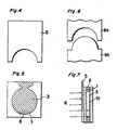
- Fig. 3 is a partial cross sectional view of the mold of Figs. 1 and 2 provided with a pair of shielding platea,
- Fig. 4 is a front view of a shielding plate,
- Fig. 5 is a front view of the mold in which a part of a monomer composition is cured,
- Fig. 6 is a partial front view of a pair of the shielding plates,
- Fig. 7 is a cross sectional view of a mold having a stamper,
- Fig. 8 is a front view of four shielding plates,
- Fig. 9 is a front view of a plastic disc plate produced in Examples 1 to 4,
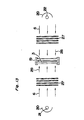
- Fig. 10A and 10B schematically show one embodiment of an apparatus for use in practicing the second method for producing a transparent plastic article according to the present invention,
- Fig. 11 schematically shows another embodiment of an apparatus for use in practicing the second method according to the present invention,
- Fig. 12 schematically shows atates of the monomer composition being polymerized by means of the apparatus of Fig. 10,
- Fig. 13 schematically shows a further embodiment of an apparatus for use in praoticing the second method according to the present invention,
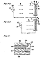
- Figs. 14A and 14B schematically shows a yet another apparatus for use in practicing the second method according to the present Invention,
- Fig. 15A and 15B show respectively a front view and a cross sectional view of a mold for use in practicing the third method for producing a transparent plastic article according to the present invention,
- Figs. 16A, 16B, 16C and 16D show states of the monomer compositon in each steps of the fourth method,
- Fig. 17 and Fig. 18 show respectively a front view and a cross sectional view of a mold for use in practicing the fourth method for producing a transparent plastic article according to the present invention, and
- Fig. 19 shows a partial sectional view of another mold for use in practicing the fourth method according to the present invention.
- According to the first aspect of the present invention, there is provided a method for producing a transparent plastic article, which comprises steps of
- (1) charging a photopolymerizable liquid monomer into a mold transparent to ultraviolet light,
- (2) irradiating a part of the monomer with ultraviolet light to form a polymerized resin part, a gel state part comprising the unreacted monomer and the polymerized resin and a part of the unreacted monomer,
- (3) flowing the gel and/or the unreacted monomer into a cavity formed in the mold by cure shrinkage of the monomer,
- (4) irradiating a wider area than the polymerized part in the previous irradiation step, and
- (5) repeating the steps (3) and (4) till the polymerized area reaches the predetermined size.
- In the context of the present specification, the "polymerized part" is intended to mean a part through which ultraviolet light is transmitted and the monomer is polymerized to cure. The "gel state part" is formed near an interface between the part which ultraviolet light reaches and the part which ultraviolet light does not reach wherein polymerization initiating speoies generated by ultraviolet light migrate into the monomer to polymerize it so as to form a gel-like mixture of the polymer and the unreacted monomer.
- In this method, the Illumination of ultraviolet light is usually from 10 to 150 mW/cm2. preferably from 30 to 100 mW/cm 2.
- The area of the part of the monomer which is cured in each irradiation step can be easily determined according to other conditions such as the composition of the monomer composition, the kind of the monomer to be polymerized, a thickness of the article and the like. Usually, the width of the polymerized part in each irradiation step is increased by 1 mm to 10 mm, preferably by 2 mm to 5 mm.
- When the area in which the monomer is polymerized in the previous step is again irradiated by ultraviolet light in the subsequent irradiation step, the final product may be unevenly cured or the polymer in that part may be decomposed. To prevent such drawbacks, the subsequent irradiation may be carried out with masking the part already cured in the previous irradiation step. Thereby, any part of the monomer can be irradiated by substantially the same illumination so that the final product has less internal cure strain therein.
- Since the polymerizable liquid monomer has a good image-transfer property, any minute pattern such as a recording groove can be formed on one surface of the cured article simultaneously with the polymerization of the monomer when a stamper is provided on one wall of the mold.
- In addition, since the raw material is the liquid monomer, it can be purified by filtration or distillation before polymerization whereby contamination of the molded article with the foreign particles which cause problems in the injection molding is prevented. In comparison with the injection molding, the molded article produced by this method contains only one hundredth to one thousandth of the foreign particles. Therefore, the molded article according to the present invention can reduce recording errors due to the foreign particles so that it can increase the recording capacity.
- According to the above method according to the first aspect of the present invention, since the gel-state part is formed between the polymerized part and the unreacted monomer part, the molded article has greatly decreased cure strain which results in crack or warp of the produced article and improved size accuracy and optical characteristics (for example, less birefringence and foreign particles). With respect to the size accuracy, although the volume of the monomer decreases due to curing, the gel and/or the unreacted monomer flow into a space formed by such shrinkage so as to prevent the formation of a gap between the monomer being cured and the already cured part. Such gap is often found in the conventional molding of thermoplastic resin, thermosetting resin or photopolymerizable resin. Thereby, the molded article having the same size accuracy as that of the mold can be produced. With respect to birefringence of the article, since the entire article is uniformly cured, the article has not more than 10 nm of birefringence at a single pass thickness of 1 mm, while the conventional polyoarbonate article has 20 to 40 nm of birefringence.
- Since the monomer is polymerized in a cold mold, burning of the resin as is found in the molding of a thermoplastic resin or generation of metal powder due to chipping of a screw are prevented so that contamination of foreign particles having a particle size of 0.5 to 1 um or more is prevented. As a result, an error rate of the disc substrate can be reduced to 10-6 to 10-9 and, in turn, a preliminary recording area formed in the conventional recording disc can be used as an actual recording area, which leads to increase of recording capacity of the disc.
- Although the same effects may be achieved with the thermosetting resin such as epoxy resin, in thermosetting, the mold is wholly heated due to heat conduction even when only a part of the mold is heated so that the polymerization proceeds with a temperature gradient in the mold and the monomer is not uniformly polymerized. This leads to cracking of the article during molding or ununiformity of birefringence. To prevent these drawbacks in the molding of the thermosetting resin, the mold should be partially heated or cooled and its temperature should be precisely controlled, which requires a mold much larger than one used in photopolymerization with ultraviolet light. Further, the thermosetting requires several ten minutes to several hours while the ultraviolet polymerization can be completed within several seconds to several ten minutes.
- According to the second aspect of the present invention, there is provided a method for producing a transparent plastic article, which comprises stepa of
- (i) charging a photopolymerizable liquid monomer into a mold transparent to ultraviolet light,
- (ii) irradiating the mold containing the monomer with ultraviolet light to form a polymerized resin layer, a gel state layer comprising the unreacted monomer and the polymerized resin and a layer of the unreacted monomer,
- (iii) flowing the gel and/or the unreacted monomer into a cavity formed in the mold by cure shrinkage of the monomer,
- (iv) irradiating the mold containing the partially polymerized monomer with ultraviolet light at an illumination larger than that in the previous irradiation step, and
- (v) repeating the steps of (iii) and (iv) till the whole monomer is polymerized.
- To increase the illumination of ultraviolet light, several manners are contemplated. For example, in the subsequent irradiation step, the ultraviolet light is irradiated from a shorter distance than in the previous irradiation step. In another manner, several extinction plates are provided between the mold and the ultraviolet light source in the first irradiation step and the subsequent irradiation steps are carried out by removing the extinction plates one by one.
- In the first irradiation step, the illumination of ultraviolet light is usually from 10 to 30 mW/cm2, preferably from 15 to 25 mW/cm2. In each subsequent irradiation step, the illumination of ultraviolet is increased by 70 to 150 mW/om2, preferably by 80 to 120 mW/cm2.
- According to the third aspect of the present invention, there is provided a method for producing a transparent plastic article, which oomprises steps of
- charging a photopolymerizable liquid monomer into a mold at least opposite two walls of which are transparent to ultraviolet light,
- irradiating the monomer through both of said transparent walls with ultraviolet light to precure the monomer at such an illumination that the monomer is not completely cured,
- removing the precured article from the mold, and post-curing the precured article.
- By this method, the formation of flow marks due to curing shrinkage and/or to decrease birefringence due to curing shrinkage are effectively prevented.
- In the above method, the illumination of ultraviolet light varies with the kind of the monomer(s) to be polymerized. Usually, it is from 10 to 150 mW/cm2, preferably from 30 to 100 mW/cm2.
- The precured polymer may be post-oured by the application of ultravi.olet light, heat or electron beam, or a combination thereof. When ultraviolet light is used, it is irradiated in 4,000 to 20,000 mJ/om2, When heat is used, temperature is from 80 to 260°C, preferebly from 150 to 250°C. When electron beam is used, its energy is up to 750 KeV or 10 Mrad.
- When the post-curing is thermally effected, it is preferably carried out in an inerg gas atmosphere such as nitrogen,
- In the above method, since the artiole is removed from the mold in the precured state, crack or warp induced by unbalance of the adherence force with the mold surface can be prevented. Since the procured article is post cured from both side, the both surfaces of the article uniformly shrink so that the article with less internal strain is produced, and any crack is not caused on the article surfaces.
- In the present invention, the polymerizable liquid monomer may comprise a monomer which is liquid at room temperature or a mixture of monomers which is liquid at room temperature. According to the present invention, any photopolymerizable monomer may be used although its polymerization rate varies.
- As the polymerizabie. liquid monomer, preferably used is a composition of polyfunctional (meth)acrylate and a thermal polymerization initiator and/or a photosensitizer. A preferred example of polyfunctional (meth)aorylate is a compound of the formula:

- Specific examples of the polyfunctional (meth)-acrylate (I) are 2,2'-bis[4-(β-methacryloyloxy)cyclohexyl]-propane, 2,2'-bis[4-(β-methacryloyloxydiethoxy)cyelohexyl]-propane, bis(oxymethyl)tricyclo[5.2,1.02,6]decane di(meth)-acrylate, 1,4-bis(methacryloyloxymethyl)cyelohexane, trimethylolpropane tri(meth)aerylate, neopentyl glycol di-(meth)acrylate, 1,6-hexanediol di(meth)acrylate, 1,3-butanediol di(meth)acrylate, diethylene glycol di(meth)acrylate, 2,2'-bis[4-(methacryloyldiethoxy)prenylpropane, Bisphenol A di(meth)acrylate and mixtures thereof. Among then, 2,2'- bis[4-β-methacryloyloxyethoxy)cyclohexyl]propane, bis(oxymethyl)tricyclo[5.2,1.02,6]decane di(meth)acrylate and 1,4- bis(methacryloyloxymethyl)cyclohexane are most preferred in view of the optical properties.
- The (meth)acrylate (I) may contain a radically polymerizable monomer which is generally used as a viscosity modifier. Examples of such additional monomer are vinyl compounds (e.g., styrene, chlorostyrene, dichlorostyrene, vinyltoluene, divinyltoluene, vinyl acetate, vinyl chloride and the like), (meth)aorylates (e.g., methyl methaorylate, phenyl (meth)aorylate, benzyl (meth)aorylate, 2-phenoxyethyl (meth)aorylate, oyolohexyl (meth)acrylate, glycidyl (meth)-acrylate, epoxy (meth)acrylate, urethane (meth)acrylate and the like) and acrylic compounds (e.g., diethylene glycol bisallylcarbonate, diallyl phthalate and the like).
- For polymerizing the monomer(s), any radical polymerization initiator can be used. Examples of the radical polymerization initiator are peroxy compounds (e.g., benzoyl peroxide, diieopropyl peroxyoarbonate, lauroyl peroxide, t-butyl peroxypivalate and the like), azo compounds (e.g., azoisobutyronitrile and the like), photosensitizers (e.g., benzophenone, benzoin ethyl ether, dibenzoyl, acetophenone, anthraquinone and the like) and sulfur containing compounds (e.g., diphenyl sulfite, thiocarbamate and the like) as well as mixtures thereof. The radial initiator may be used in an amount of 0.1 to 10 % by weight based on the weight of the monomer.
- The present invention further relates to a method for producing a thin plastic plate with low strain by polymerizing a liquid monomer by the application of heat or ultraviolet light, which comprises steps of charging a monomer in a cavity of a mold having a spacer which shrinks in such a manner that it can follow polymerization shrinkage of the monomer being polymerized, applying heat or ultraviolet light to polymerize the monomer to such extent that the polymerited monomer is hard enough to be removed from the mold and then further applying heat or ultraviolet light to complately polymerize the monomer to obtain a plactio plate.
- The thickness of the plaetio plate to be produced by the above method is usually from 0.5 to 5 mm, preferably from 1 to 3 mm.
- In this method, illumination of ultraviolet light may be the eame as in the above methode of the present invention. When heat is applied, temperature also depends on the kind of the monomer(s) and usually from 80 to 150°C, preferably from 80 to 120°C. A polymerization time is usually from 30 to 70 minutes, preferably from 45 to 60 minutes.
- Examples of the thermally polymerizable monomer are bis(oxymethyl)trioyolo[5.2,1.02,6]deoane di(methaorylate) and the like.
- The spacer is preferably made of a flexible rubber or resin, particularly one having Shore A hardness of 70 or less,
- The volume of the photopolymerizable liquid polymer deoreases ae the polymerization proceeds (polymerization or oure shrinkage). Although a degree of the oure shrinkage is large in a direction aoross the thiokness, the applioa- tion of the apacer can prevent partial peeling off of the polymer from a inner aurface of the mold and movement of the unpolymerized monomer into a space formed by the shrinkage of the monomer, whereby formation of flow mark is prevented. Since the plate in a partially polymerized (preoure) state is removed from the mold and thereafter completely cured (post cure), the produced plate such as a disc substrate has less strain so that it has low birefringenoe. In this method, a mold having a metal stamper on its one wall can be used.
- Practically and presently preferred embodiments of the present invention will be illustrated in the following examples.
- A mold used in this example for producing a disc substrate is schematically shown in Figs. 1 and 2. The mold 19 comprises a pair of
quartz glass plates 1 which tare held together by means of closing clamps through aspacer 2 which is made of a fluororesin having a predetermined thickness. The photopolymerizableliquid monomer composition 3 is charged into a cavity of themold 19. In Fig. 2, "P" stands for a space in which the disc substrate is formed and "Q" stands for a space for charging the monomer composition into the space P. - Then, as shown in Fig. 3, the most part of the space P of the mold containing the monomer composition is covered by a
shielding plate 5 shown in Fig. 4, and the unshielded part of the space P is irradiated byultraviolet light 6 from a direction vertical to the plane of thequartz glass plate 1 to polymerize the monomer composition in the unshielded part of the space P. Thereby, as shown in Fig. 5, there are formed a region of theunreacted monomer composition 3, a region of gel 7 and a cured region 8 in the space P. - Thereafter, the shielding
plate 5 is gradually moved to widen the area of the unshielding part and the above irradiation procedure is repeated to increase the oured region 8. These procedures are repeated till all the monomer in the space P is cured to produce a cured product having a shape of the space P. Finally, the monomer composition in the space Q is cured by the irradiation of ultraviolet light. - In Example 1, the monomer composition contained, as a bifunctional di(meth)acrylate, Bisphenol A diacrylate (BP4EA, a trade name of Kyoeisha Yushi Kagaku Kogyo Kabushikikaisha); as a trifunctional acryalate, trimethylolpropane triacrylate (TMPTA); as an epoxy methacrylate, 3002 M (manufactured by Kyoeisha Yushi Kagaku Kogyo); and as a monofunctional methacrylate, methyl methacrylate (MMA), As the polymerization initiator, Irgacure 184 (Trade mark, Ciba-Geigy. Active ingredients 1-hydroxycyolohexyl phenyl ketone) was used since it causes less yellowing of the polymer and does not deteriorate transparency of the polymer, although almost all the commercially available polymerization initiator can be used. Amounts of these components were as follows:

- A thickness and a diameter of the produced disc were 1.2 mm and 13 cm, respectively.
- In substantially the same manner as in Example 1 except that a pair of upper and
lower shielding plates 9a and 9b as shown in Fig. 6 were used in place of theshielding plate 5, a plastic disc substrate was produced. - One of the shielding plates 9a acted as the shielding
plate 5 used in Example 1 and the other 9b prevented excess irradiation of the cured material. - In the same manner as in Example 1 but providing a
stamper 10 on an inner surface of either one of thequartz glass plates 1 so as to transfer a recording groove on the molded substrate, a plastic disc substrate was produced. - In the same manner as in Example 1 but using four
shielding plates 5 as shown in Fig. 8 and moving them in four directions ofarrows - In Examples 1 to 4, as an ultraviolet light source, an extra-high pressure mercury lamp (Jet Light JL-3300 manufactured by Oak Seisakusho. 3 KW) was used to irradiate ultraviolet light at 50 mW/cm2.
- Birefringence of the produced substrate was measured at a
central part 16, a middle part 17 and aperipheral part 18 near a gate of the produced disc substrate as shown in Fig, 9 by means of a polarization microscope (OPTIPHOT-POL manufactured by Nippon Kogaku) with magnification of 200 times. A shrinkage factor of the substrate with respeot to the mold size at the periphery of the substrate was calculated. - The results are shown in Table 1.

- In this example, an apparatus as shown in Figs. 10A and 10B was used, In this apparatus, the
mold 19 was substantially the same as used in Example 1 except that any shielding plate was not provided with, and a pair ofultraviolet lamps reflection mirror 20 to produceparallel rays 6 were used. - The
photopolymerizable monomer composition 3 in themold 19 was irradiated by ultraviolet light from a distance of Ln and then from a distance of Ln+1 wherein Ln+1 was always shorter than Ln so as to increase illuminance of ultraviolet light, - If ultraviolet light is irradiated form one side of the mold, the produced polymer article, particularly a plate tends to deform, for example, warp. Therefore, it is preferred to use a pair of the lamp arranged symmetrically with respect to the mold.
- When only one ultraviolet light source is used, the mold is preferably mounted on a
rotating plate 23 and rotated at an adequate revolution rate as shown in Fig. 11. - After the
monomer composition 3 was irradiated from the distance of Ln, asurface layer 24 of the oomposi- tion was cured and adeeper portion 26 of the composition remained unoured. Between the curedlayer 24 and theunoured portion 26, agel layer 25 was formed. When the monomer composition was irradiated from a shorter distance of Ln+1, illumination increased so that ultraviolet light reached to a more deeper layer whereby the thickness of the curedlayer 24 increased. By repeating these procedures, the entire monomer composition was cured to form a transparent plastic article. - In this example, an apparatus shown in Fig. 13 was used, wherein a pair of ultraviolet lamps were fixed at the same predetermined distances from the
mold 19, andseveral extinction plates 27 were provided with between themold 19 and eachlamp - In the first step, the
monomer composition 3 was irradiated byultraviolet light 28 intensity of which was decreased by theextinction plates 27. After the composition was irradiated one or more times, one of the extinction plates was removed to increase the intensity of ultraviolet light which reached the monomer composition so that the deeper layer of the composition was cured. By repeating these procedures, the entire monomer composition was cured to form a transparent plastic plate. - The extinction plate may be colored to limit a wavelength band to be irradiated on the monomer composition.
- The movement of the ultraviolet lamps as in Example 5 and the provision of the extinction plates as in Example 6 may be combined.
- In the same manner as in Example 5 except that a
stamper 10 was provided on one of thequartz glass plates 1 and ultraviolet light was irradiated through the other quartz glass plate with changing a distance between the ultraviolet lamp and the mold as shown in Figs. 14A and 14B, a plastic article was produced. - In this example, as an ultraviolet light source, an extra-high pressure mercury lamp (Jet Light JL-3300 manufactured by Oak Seisakusho. 3 KW) was used and moved so that ultraviolet illumination varied from 1 to 100 mW/cm2.
- Birefringence and shrinkage rates of the articles produced in Examples 5, 6 and 7 are shown in Table 2,

- Figs. 15A and 15 B show a front and vertical cross sectional views of a oasting mold, respectively. The mold comprises a pair of
glass plates clamps 33 through outer andinner spacers plates monomer composition 36 is injected from anopening 34 and air in the space is exhausted from anopening 35. - The curing procedures in this example will be explained with reference to Figs. 16A to 16D, which show enlarged view of a part of the mold of Fig. 15B encircled by a circle B. The monomer composition used in this example contained TMPTA and a compound of the formula:

- The injected
monomer composition 36 of Fig. 16A was irradiated by ultraviolet light and cured to a precure state of Fig. 16B. Then, the composition in theprecure state 37 was removed from the mold (Fig. 16C) and further irradiated by ultraviolet light to produce a post-oured transparent plastic article 38 (Fig. 16D). - Heat resistance, birefringence, water absorbance, productivity and appearance of the produced article are shown in Table 3.
- In Comparative Examples 1 and 2, a transparent plastic article was produced by injection molding from PC and PMMA, respeotively, In Comparative Examples 3 and 4, a transparent plastic article was produced by thermally polymerizing CR-39 (manufactured by UCC) and an epoxy composition containing Epikote 828 (an epoxy resin manufactured by Yuka-Shell Epoxy), HHPA (hexahydrophthalic anhydride manufactured by Shin-Nippon Rika) and Irgacure 184 as a photosensitizer. Heat resistance, birefringence, water absorbance, productivity and appearance of the produced articles are shown in Table 3.

- In this example, a mold shown in Figs. 17 and 18 were used for low strain polymerization according to the present invention. The
mold 39 comprises upper and lowerquartz glass plates ahaped spacers axis pore 47. - A monomer composition comprising methyl mothaory- late (7) was injected from an
opening 44 with holding said opening upwardly till the composition overflew from anopening 45. - The monomer composition was precured by application of heat or irradiation of ultraviolet light through both glass plates. The polymerization was stopped when the cured composition was about to separate from the inner aur- faces of the glass plates and the olamp was detached, Then, the procured composition was removed from the mold and completely oured by application of heat or irradiation of ultraviolet light in an atmosphere of inert gas such as helium.
- Preferably, the apacers have thickness of 5 mm or more so as to follow shrinkage of the composition during curing. In case of eilioone rubber, it has preferably Shore A hardness of not more than 100, preferably not more than 70. When the epacer has Shore A hardness more than 100, it shows less deformation in a rubbery elastomeric region, Therefore, when the monomer is oured to such extent that it can be removed from the mold, it is partly released from the mold wall so that a boundary line between the released part and the unreleased area generetes a flow mark. If the spaoer has Shore A hardnesa more than 100, its thiokneas should be 2 or 3 mm. Aa a apacer material which does not inhibit radical polymerization, urethane rubber, ethylene/ vinyl acetate (EVA) polymere and the like are preferred although they have aome drawbaoka that, after repeated use, urethane rubber tends to adhere to the acrylio material and EVA tenda to be deformed. Neverthelesa, the spacer made of an elastomer such as urethane rubber and neoprene and a visoelastically deformable material such as EVA is effective in preventing formation of flow mark and in low strain polymerization according to the present invention,
- Fig. 19 showe a cross sectional view of a part of a repeatedly usable spacer made of metal. The
mold 39 comprises upper andlower glass glass supporting member 52, ametal specer 53, aflexible packing 54 which is baked or adhered onto the metal apacer and aflexible relaxation member 55. As themonomer composition 56 is oured, theglass plate 50 follows shrinkage of the composition because of theflexible packing 54 and theflexible relaxation member 55 elastioally or viscoelastionlly deforms. Acoording to this design of the mold, since a volume of the flexible packing is rather small, an unreacted state of the composition near the periphery of the diso subatrate can be avoided. - When MMA is used as a monomer, the oonventional disc aubstrate has birefringence of 10 to 20 nm at 810 nm by single pass while a disc subatrate made by means of the mold of Fig. 19 had birefringence less than 5 nm..
Claims (8)
Applications Claiming Priority (8)
| Application Number | Priority Date | Filing Date | Title |
|---|---|---|---|
| JP60271851A JPH0729308B2 (en) | 1985-12-03 | 1985-12-03 | Method for manufacturing transparent molded plate |
| JP271851/85 | 1985-12-03 | ||
| JP60283444A JPH0729309B2 (en) | 1985-12-17 | 1985-12-17 | Method for manufacturing transparent resin plate |
| JP283444/85 | 1985-12-17 | ||
| JP32311/86 | 1986-02-17 | ||
| JP3231186A JPH0716959B2 (en) | 1986-02-17 | 1986-02-17 | Method for producing transparent plastic body |
| JP5721686A JPH0729310B2 (en) | 1986-03-14 | 1986-03-14 | Low strain polymerization method for reactive liquid materials |
| JP57216/86 | 1986-03-14 |
Publications (2)
| Publication Number | Publication Date |
|---|---|
| EP0226123A2 true EP0226123A2 (en) | 1987-06-24 |
| EP0226123A3 EP0226123A3 (en) | 1988-08-10 |
Family
ID=27459586
Family Applications (1)
| Application Number | Title | Priority Date | Filing Date |
|---|---|---|---|
| EP86116782A Withdrawn EP0226123A3 (en) | 1985-12-03 | 1986-12-03 | Method for producing transparent plastic article |
Country Status (2)
| Country | Link |
|---|---|
| US (1) | US4983335A (en) |
| EP (1) | EP0226123A3 (en) |
Cited By (48)
| Publication number | Priority date | Publication date | Assignee | Title |
|---|---|---|---|---|
| EP0307322A1 (en) * | 1987-09-11 | 1989-03-15 | Framatome | Method for producing a resinous article part by photopolymerisation, and use of this method |
| FR2622835A1 (en) * | 1987-11-09 | 1989-05-12 | Ocutech | PROCESS AND APPARATUS FOR PRODUCING MOLDED ARTICLES, IN THERMOSETTING AND THERMOPLASTIC MATERIALS, IN PARTICULAR FOR CONTACT LENSES FOR OPHTHALMIC USE |
| EP0322353A2 (en) * | 1987-12-21 | 1989-06-28 | Matsushita Electric Industrial Co., Ltd. | Method and apparatus for producing optical element |
| US4919850A (en) * | 1988-05-06 | 1990-04-24 | Blum Ronald D | Method for curing plastic lenses |
| EP0369781A2 (en) * | 1988-11-16 | 1990-05-23 | Canon Kabushiki Kaisha | Process and apparatus for producing substrate sheet for optical recording medium |
| EP0369780A2 (en) * | 1988-11-16 | 1990-05-23 | Canon Kabushiki Kaisha | Process for producing optical recording medium |
| GB2227969A (en) * | 1989-01-27 | 1990-08-15 | Pilkington Visioncare Holdings | Casting lenses in plastic: curing by radiation |
| WO1990013413A1 (en) * | 1989-05-01 | 1990-11-15 | Polymer Systems, Inc. | Controlled casting of shrinkable material |
| EP0427845A1 (en) * | 1989-05-01 | 1991-05-22 | SOANE, David S. | Gel casting method and apparatus |
| WO1991008104A1 (en) * | 1989-12-05 | 1991-06-13 | Vision Science, Inc. | Method for forming plastic optical quality spectacle |
| WO1991008105A2 (en) * | 1989-12-05 | 1991-06-13 | Blum Ronald D | Method for forming plastic optical quality spectacle lenses |
| EP0484015A2 (en) * | 1990-10-30 | 1992-05-06 | Minnesota Mining And Manufacturing Company | Method for curing ocular devices |
| WO1992012851A2 (en) * | 1991-01-17 | 1992-08-06 | Ophthalmic Research Group International Corp. | Method and apparatus for the production of plastic lenses |
| US5178800A (en) * | 1990-10-10 | 1993-01-12 | Innotech, Inc. | Method for forming plastic optical quality spectacle lenses |
| WO1994004345A2 (en) * | 1992-08-18 | 1994-03-03 | Q2100, Inc. | Apparatus and process for lens curing and coating |
| US5364256A (en) | 1986-01-28 | 1994-11-15 | Ophthalmic Research Group International, Inc. | Apparatus for the production of plastic lenses |
| EP0637490A1 (en) * | 1993-07-19 | 1995-02-08 | Ciba-Geigy Ag | Process and device for production of moulded parts as well as the so manufactured parts |
| US5514214A (en) | 1993-09-20 | 1996-05-07 | Q2100, Inc. | Eyeglass lens and mold spin coater |
| EP0686483A3 (en) * | 1994-06-10 | 1996-11-27 | Johnson & Johnson Vision Prod | Mold clamping and precure of a polymerizable hydrogel |
| WO1998028126A2 (en) * | 1996-12-20 | 1998-07-02 | Innotech, Inc. | Polymeric processing system for producing ophthalmic lenses |
| WO1998036889A1 (en) * | 1997-02-21 | 1998-08-27 | Novartis Ag | Apparatus for the photo-initiated chemical cross-linking of material |
| US5989462A (en) * | 1997-07-31 | 1999-11-23 | Q2100, Inc. | Method and composition for producing ultraviolent blocking lenses |
| EP0985520A2 (en) * | 1998-05-15 | 2000-03-15 | Menicon Co., Ltd. | Mold assembly for forming opthalmic lens, method of producing the same, and method of producing opthalmic lens using the mold assembly |
| WO2000018569A2 (en) * | 1998-09-25 | 2000-04-06 | Q2100, Inc. | Plastic lens systems, compositions and methods |
| US6086799A (en) * | 1996-04-19 | 2000-07-11 | Q2100, Inc. | Methods and apparatus for eyeglass lens curing using ultraviolet light and improved cooling |
| US6201037B1 (en) | 1986-01-28 | 2001-03-13 | Ophthalmic Research Group International, Inc. | Plastic lens composition and method for the production thereof |
| US6419873B1 (en) | 1999-03-19 | 2002-07-16 | Q2100, Inc. | Plastic lens systems, compositions, and methods |
| US6464484B1 (en) | 2002-03-30 | 2002-10-15 | Q2100, Inc. | Apparatus and system for the production of plastic lenses |
| US6612828B2 (en) | 2001-02-20 | 2003-09-02 | Q2100, Inc. | Fill system with controller for monitoring use |
| US6630083B1 (en) | 1999-12-21 | 2003-10-07 | Johnson & Johnson Vision Care, Inc. | Methods and compositions for the manufacture of ophthalmic lenses |
| US6632535B1 (en) | 2000-06-08 | 2003-10-14 | Q2100, Inc. | Method of forming antireflective coatings |
| US6655946B2 (en) | 2001-02-20 | 2003-12-02 | Q2100, Inc. | Apparatus for preparing an eyeglass lens having a controller for conveyor and curing units |
| US6676398B2 (en) | 2001-02-20 | 2004-01-13 | Q2100, Inc. | Apparatus for preparing an eyeglass lens having a prescription reader |
| US6676399B1 (en) | 2001-02-20 | 2004-01-13 | Q2100, Inc. | Apparatus for preparing an eyeglass lens having sensors for tracking mold assemblies |
| US6698708B1 (en) | 2000-03-30 | 2004-03-02 | Q2100, Inc. | Gasket and mold assembly for producing plastic lenses |
| US6702564B2 (en) | 2001-02-20 | 2004-03-09 | Q2100, Inc. | System for preparing an eyeglass lens using colored mold holders |
| US6709257B2 (en) | 2001-02-20 | 2004-03-23 | Q2100, Inc. | Eyeglass lens forming apparatus with sensor |
| US6712331B2 (en) | 2001-02-20 | 2004-03-30 | Q2100, Inc. | Holder for mold assemblies with indicia |
| US6716375B1 (en) | 2000-03-30 | 2004-04-06 | Q2100, Inc. | Apparatus and method for heating a polymerizable composition |
| US6723260B1 (en) | 2000-03-30 | 2004-04-20 | Q2100, Inc. | Method for marking a plastic eyeglass lens using a mold assembly holder |
| US6726463B2 (en) | 2001-02-20 | 2004-04-27 | Q2100, Inc. | Apparatus for preparing an eyeglass lens having a dual computer system controller |
| US6752613B2 (en) | 2001-02-20 | 2004-06-22 | Q2100, Inc. | Apparatus for preparing an eyeglass lens having a controller for initiation of lens curing |
| US6790022B1 (en) | 2001-02-20 | 2004-09-14 | Q2100, Inc. | Apparatus for preparing an eyeglass lens having a movable lamp mount |
| US6790024B2 (en) | 2001-02-20 | 2004-09-14 | Q2100, Inc. | Apparatus for preparing an eyeglass lens having multiple conveyor systems |
| US6800225B1 (en) | 1994-07-14 | 2004-10-05 | Novartis Ag | Process and device for the manufacture of mouldings and mouldings manufactured in accordance with that process |
| US6808381B2 (en) | 2001-02-20 | 2004-10-26 | Q2100, Inc. | Apparatus for preparing an eyeglass lens having a controller |
| US6997693B2 (en) | 2001-10-19 | 2006-02-14 | Novartis Ag | Casting mold half and casting mold for producing contact lenses |
| US7143990B2 (en) | 2001-03-26 | 2006-12-05 | Novartis Ag | Apparatus and method for the production of ophthalmic lenses |
Families Citing this family (44)
| Publication number | Priority date | Publication date | Assignee | Title |
|---|---|---|---|---|
| US6730244B1 (en) | 1986-01-28 | 2004-05-04 | Q2100, Inc. | Plastic lens and method for the production thereof |
| US5114632A (en) * | 1989-05-01 | 1992-05-19 | Soane Technologies, Inc. | Controlled casting of a shrinkable material |
| JPH0558950A (en) * | 1991-06-21 | 1993-03-09 | Nippon Kayaku Co Ltd | (meth)acrylic acid ester |
| US5260928A (en) * | 1992-03-06 | 1993-11-09 | Digital Equipment Corporation | Apparatus and method for fabricating a lens/mirror tower |
| US5422046A (en) * | 1993-08-31 | 1995-06-06 | Essilor Of America, Inc. | Method for producing optical lenses |
| US5730911A (en) * | 1995-03-03 | 1998-03-24 | Essilor International-Compagnie General D'optique | Process for the manufacture of a substrate made of transparent organic glass and substrate thus obtained |
| US5938891A (en) * | 1996-02-27 | 1999-08-17 | Origin Electric Company, Limited | Disk bonding system |
| US6280171B1 (en) | 1996-06-14 | 2001-08-28 | Q2100, Inc. | El apparatus for eyeglass lens curing using ultraviolet light |
| US6107008A (en) * | 1997-08-29 | 2000-08-22 | Lockheed Martin Energy Research | Ionizing radiation post-curing of objects produced by stereolithography and other methods |
| US7179551B2 (en) | 1999-02-12 | 2007-02-20 | General Electric Company | Poly(arylene ether) data storage media |
| KR100755089B1 (en) | 1999-02-12 | 2007-09-03 | 제너럴 일렉트릭 캄파니 | Data storage media |
| SI20291A (en) * | 1999-06-15 | 2000-12-31 | In�titut "Jo�ef Stefan" | Process for production of compensational polymeric layer for lcd optical switches and construction of such switch |
| US6960312B2 (en) | 2000-03-30 | 2005-11-01 | Q2100, Inc. | Methods for the production of plastic lenses |
| US20020000290A1 (en) * | 2000-06-29 | 2002-01-03 | Crump Larry Scott | Curing of a gel coat on a mold |
| US6537479B1 (en) | 2000-08-24 | 2003-03-25 | Colbar Art, Inc. | Subsurface engraving of three-dimensional sculpture |
| US7037449B2 (en) | 2001-02-20 | 2006-05-02 | Q2100, Inc. | Method for automatically shutting down a lens forming apparatus |
| US7025910B2 (en) | 2001-02-20 | 2006-04-11 | Q2100, Inc | Method of entering prescription information |
| US7124995B2 (en) * | 2001-02-20 | 2006-10-24 | Q2100, Inc. | Holder for mold assemblies and molds |
| US7060208B2 (en) | 2001-02-20 | 2006-06-13 | Q2100, Inc. | Method of preparing an eyeglass lens with a controller |
| US6962669B2 (en) | 2001-02-20 | 2005-11-08 | Q2100, Inc. | Computerized controller for an eyeglass lens curing apparatus |
| US7045081B2 (en) | 2001-02-20 | 2006-05-16 | Q2100, Inc. | Method of monitoring components of a lens forming apparatus |
| US6863518B2 (en) | 2001-02-20 | 2005-03-08 | Q2100, Inc. | Mold filing apparatus having multiple fill stations |
| US6899831B1 (en) | 2001-02-20 | 2005-05-31 | Q2100, Inc. | Method of preparing an eyeglass lens by delayed entry of mold assemblies into a curing apparatus |
| US7083404B2 (en) * | 2001-02-20 | 2006-08-01 | Q2100, Inc. | System for preparing an eyeglass lens using a mold holder |
| US6875005B2 (en) | 2001-02-20 | 2005-04-05 | Q1200, Inc. | Apparatus for preparing an eyeglass lens having a gating device |
| US7052262B2 (en) | 2001-02-20 | 2006-05-30 | Q2100, Inc. | System for preparing eyeglasses lens with filling station |
| US6893245B2 (en) | 2001-02-20 | 2005-05-17 | Q2100, Inc. | Apparatus for preparing an eyeglass lens having a computer system controller |
| US7074352B2 (en) | 2001-02-20 | 2006-07-11 | Q2100, Inc. | Graphical interface for monitoring usage of components of a lens forming apparatus |
| US6758663B2 (en) | 2001-02-20 | 2004-07-06 | Q2100, Inc. | System for preparing eyeglass lenses with a high volume curing unit |
| US7139636B2 (en) * | 2001-02-20 | 2006-11-21 | Q2100, Inc. | System for preparing eyeglass lenses with bar code reader |
| US7051290B2 (en) * | 2001-02-20 | 2006-05-23 | Q2100, Inc. | Graphical interface for receiving eyeglass prescription information |
| US7004740B2 (en) | 2001-02-20 | 2006-02-28 | Q2100, Inc. | Apparatus for preparing an eyeglass lens having a heating system |
| US7011773B2 (en) | 2001-02-20 | 2006-03-14 | Q2100, Inc. | Graphical interface to display mold assembly position in a lens forming apparatus |
| US6840752B2 (en) * | 2001-02-20 | 2005-01-11 | Q2100, Inc. | Apparatus for preparing multiple eyeglass lenses |
| KR20030090761A (en) * | 2001-04-19 | 2003-11-28 | 제너럴 일렉트릭 캄파니 | Spin coated media |
| SE0101702D0 (en) * | 2001-05-15 | 2001-05-15 | Ardenia Investments Ltd | Novel potentiating compounds |
| WO2004002708A1 (en) * | 2001-06-26 | 2004-01-08 | Energy Conversion Devices, Inc | Method and apparatus for forming microstructures on polymeric substrates |
| US7044429B1 (en) | 2002-03-15 | 2006-05-16 | Q2100, Inc. | Methods and systems for coating eyeglass lens molds |
| JP2004046093A (en) * | 2002-05-24 | 2004-02-12 | Canon Inc | Method for manufacturing diffraction optical element |
| JP2005119940A (en) * | 2003-09-26 | 2005-05-12 | Nippon Sheet Glass Co Ltd | Etched article, mold structure using the same and method for production thereof |
| US20060065989A1 (en) * | 2004-09-29 | 2006-03-30 | Thad Druffel | Lens forming systems and methods |
| WO2008020867A2 (en) * | 2005-11-21 | 2008-02-21 | Q2100, Inc. | Methods of making and using metal oxide nanoparticles |
| US7938252B2 (en) * | 2007-12-21 | 2011-05-10 | Cinetic Sorting Corp. | Unstacking conveyor with floating surface |
| JP2012032528A (en) * | 2010-07-29 | 2012-02-16 | Sony Corp | Lens forming method, lens, and camera module |
Citations (9)
| Publication number | Priority date | Publication date | Assignee | Title |
|---|---|---|---|---|
| US4166088A (en) * | 1977-05-25 | 1979-08-28 | Neefe Charles W | Method of making high quality plastic lenses |
| US4257988A (en) * | 1978-09-12 | 1981-03-24 | Optical Warehouse Showroom And Manufacturing, Inc. | Method and assembly for molding optical lenses |
| JPS5842436A (en) * | 1981-09-04 | 1983-03-11 | Matsushita Electric Ind Co Ltd | Manufacture of signal record carrier |
| JPS58166024A (en) * | 1982-03-29 | 1983-10-01 | Olympus Optical Co Ltd | Molding die for plastic lens |
| JPS58187315A (en) * | 1982-04-28 | 1983-11-01 | Olympus Optical Co Ltd | Mold for plastic lens |
| US4439291A (en) * | 1979-12-22 | 1984-03-27 | Ciba-Geigy Corporation | Acrylate-containing compositions and their polymerization |
| JPS5970508A (en) * | 1982-10-15 | 1984-04-21 | Matsushita Electric Works Ltd | Molding of photosetting molding material |
| JPS59232826A (en) * | 1983-06-17 | 1984-12-27 | Hitachi Ltd | Manufacture of base plate for photo disc |
| EP0156372A2 (en) * | 1984-03-28 | 1985-10-02 | Hitachi, Ltd. | Process for producing plastic information-recording medium and resin composition used therefor |
Family Cites Families (10)
| Publication number | Priority date | Publication date | Assignee | Title |
|---|---|---|---|---|
| US2687555A (en) * | 1950-12-27 | 1954-08-31 | Gen Aniline & Film Corp | Casting of alpha-chloroacrylic ester polymers |
| DE1495381B2 (en) * | 1963-09-07 | 1971-06-24 | Czeskoslovenska akademie ved , Prag | METHOD FOR MANUFACTURING CONTACT LENSES OR CONTACT LENS BLOCKS FROM SWELLABLE HYDROGELS |
| US4113224A (en) * | 1975-04-08 | 1978-09-12 | Bausch & Lomb Incorporated | Apparatus for forming optical lenses |
| US4123407A (en) * | 1976-11-26 | 1978-10-31 | American Optical Corporation | Hydrophilic contact lens |
| JPS55132221A (en) * | 1979-04-03 | 1980-10-14 | Matsushita Electric Ind Co Ltd | Manufacture of plastic lens |
| US4497754A (en) * | 1979-07-30 | 1985-02-05 | Societa' Italiana Lenti S.I.L.-S.R.L. | Casting plastic lenses from thermohardening monomer with compensation for polymer expansion and shrinkage |
| JPS5971830A (en) * | 1982-10-18 | 1984-04-23 | Nippon Sheet Glass Co Ltd | Manufacture of lens of refractive index distribution type |
| US4701288A (en) * | 1985-06-05 | 1987-10-20 | Bausch & Lomb Incorporated | Method of making articles of dissimilar polymer compositions |
| US4732715A (en) * | 1985-09-20 | 1988-03-22 | Bausch & Lomb Incorporated | Manufacture of polymeric contact lenses |
| US4702574A (en) * | 1985-10-15 | 1987-10-27 | Bausch & Lomb Incorporated | Contact lenses having fluorescent colorants and apparatus for making such lenses |
-
1986
- 1986-12-03 EP EP86116782A patent/EP0226123A3/en not_active Withdrawn
-
1988
- 1988-12-29 US US07/291,352 patent/US4983335A/en not_active Expired - Lifetime
Patent Citations (9)
| Publication number | Priority date | Publication date | Assignee | Title |
|---|---|---|---|---|
| US4166088A (en) * | 1977-05-25 | 1979-08-28 | Neefe Charles W | Method of making high quality plastic lenses |
| US4257988A (en) * | 1978-09-12 | 1981-03-24 | Optical Warehouse Showroom And Manufacturing, Inc. | Method and assembly for molding optical lenses |
| US4439291A (en) * | 1979-12-22 | 1984-03-27 | Ciba-Geigy Corporation | Acrylate-containing compositions and their polymerization |
| JPS5842436A (en) * | 1981-09-04 | 1983-03-11 | Matsushita Electric Ind Co Ltd | Manufacture of signal record carrier |
| JPS58166024A (en) * | 1982-03-29 | 1983-10-01 | Olympus Optical Co Ltd | Molding die for plastic lens |
| JPS58187315A (en) * | 1982-04-28 | 1983-11-01 | Olympus Optical Co Ltd | Mold for plastic lens |
| JPS5970508A (en) * | 1982-10-15 | 1984-04-21 | Matsushita Electric Works Ltd | Molding of photosetting molding material |
| JPS59232826A (en) * | 1983-06-17 | 1984-12-27 | Hitachi Ltd | Manufacture of base plate for photo disc |
| EP0156372A2 (en) * | 1984-03-28 | 1985-10-02 | Hitachi, Ltd. | Process for producing plastic information-recording medium and resin composition used therefor |
Non-Patent Citations (5)
| Title |
|---|
| PATENT ABSTRACTS OF JAPAN, vol. 7, no. 124 (M-218)[1269], 28th May 1983; & JP-A-58 042 436 (MATSUSHITA DENKI SANGYO K.K.) 11-03-1983 * |
| PATENT ABSTRACTS OF JAPAN, vol. 8, no. 180 (M-318)[1617], 18th August 1984; & JP-A-59 070 508 (MATSUSHITA DENKO K.K.) 21-04-1984 * |
| PATENT ABSTRACTS OF JAPAN, vol. 8, no. 2 (M-266)[1439], 7th January 1984; & JP-A-58 166 024 (OLYMPUS KOGAKU KOGYO K.K.) 01-10-1983 * |
| PATENT ABSTRACTS OF JAPAN, vol. 8, no. 28 (M-274)[1465], 7th February 1984; & JP-A-58 187 315 (OLYMPUS KOGAKU KOGYO K.K.) 01-11-1983 * |
| PATENT ABSTRACTS OF JAPAN, vol. 9, no. 111 (M-379)[1834], 15th May 1985; & JP-A-59 232 826 (HITACHI SEISAKUSHO K.K.) 27-12-1984 * |
Cited By (86)
| Publication number | Priority date | Publication date | Assignee | Title |
|---|---|---|---|---|
| US6206673B1 (en) | 1986-01-28 | 2001-03-27 | Ophthalmic Research Group International, Inc. | Plastic lens and plastic lens manufacturing system |
| US5529728A (en) | 1986-01-28 | 1996-06-25 | Q2100, Inc. | Process for lens curing and coating |
| US5364256A (en) | 1986-01-28 | 1994-11-15 | Ophthalmic Research Group International, Inc. | Apparatus for the production of plastic lenses |
| US5415816A (en) | 1986-01-28 | 1995-05-16 | Q2100, Inc. | Method for the production of plastic lenses |
| US6201037B1 (en) | 1986-01-28 | 2001-03-13 | Ophthalmic Research Group International, Inc. | Plastic lens composition and method for the production thereof |
| US5516468A (en) | 1986-01-28 | 1996-05-14 | Q2100, Inc. | Method for the production of plastic lenses |
| FR2620374A1 (en) * | 1987-09-11 | 1989-03-17 | Framatome Sa | PROCESS FOR MAKING A RESIN PART BY PHOTOPOLYMERIZATION AND APPLICATIONS THEREOF |
| EP0307322A1 (en) * | 1987-09-11 | 1989-03-15 | Framatome | Method for producing a resinous article part by photopolymerisation, and use of this method |
| US5110513A (en) * | 1987-09-11 | 1992-05-05 | Framatome | Process for producing an article made of resin by photopolymerization and applications of this process |
| WO1989002358A1 (en) * | 1987-09-11 | 1989-03-23 | Framatome | Method for fabricating a part made of resine by photopolymerization and applications of such method |
| BE1001759A5 (en) * | 1987-11-09 | 1990-02-27 | Ocutech | PROCESS AND APPARATUS FOR PRODUCING MOLDED ARTICLES, OF THERMOSETTING AND THERMOPLASTIC MATERIALS, IN PARTICULAR FOR CONTACT LENSES FOR OPHTHALMIC USE. |
| FR2622835A1 (en) * | 1987-11-09 | 1989-05-12 | Ocutech | PROCESS AND APPARATUS FOR PRODUCING MOLDED ARTICLES, IN THERMOSETTING AND THERMOPLASTIC MATERIALS, IN PARTICULAR FOR CONTACT LENSES FOR OPHTHALMIC USE |
| EP0322353A2 (en) * | 1987-12-21 | 1989-06-28 | Matsushita Electric Industrial Co., Ltd. | Method and apparatus for producing optical element |
| EP0322353A3 (en) * | 1987-12-21 | 1989-11-29 | Matsushita Electric Industrial Co., Ltd. | Method and apparatus for producing optical element |
| US4988274A (en) * | 1987-12-21 | 1991-01-29 | Dresser Industries, Inc. | Method and apparatus for producing an optical element |
| US4919850A (en) * | 1988-05-06 | 1990-04-24 | Blum Ronald D | Method for curing plastic lenses |
| EP0369780A3 (en) * | 1988-11-16 | 1991-01-09 | Canon Kabushiki Kaisha | Process for producing optical recording medium |
| EP0369781A2 (en) * | 1988-11-16 | 1990-05-23 | Canon Kabushiki Kaisha | Process and apparatus for producing substrate sheet for optical recording medium |
| EP0369781A3 (en) * | 1988-11-16 | 1991-01-09 | Canon Kabushiki Kaisha | Process and apparatus for producing substrate sheet for optical recording medium |
| US5137661A (en) * | 1988-11-16 | 1992-08-11 | Canon Kabushiki Kaisha | Process for producing optical recording medium |
| EP0369780A2 (en) * | 1988-11-16 | 1990-05-23 | Canon Kabushiki Kaisha | Process for producing optical recording medium |
| GB2227969A (en) * | 1989-01-27 | 1990-08-15 | Pilkington Visioncare Holdings | Casting lenses in plastic: curing by radiation |
| US5110514A (en) * | 1989-05-01 | 1992-05-05 | Soane Technologies, Inc. | Controlled casting of a shrinkable material |
| EP0427845A1 (en) * | 1989-05-01 | 1991-05-22 | SOANE, David S. | Gel casting method and apparatus |
| AU633093B2 (en) * | 1989-05-01 | 1993-01-21 | 2C Optics, Inc. | Controlled casting of shrinkable material |
| WO1990013413A1 (en) * | 1989-05-01 | 1990-11-15 | Polymer Systems, Inc. | Controlled casting of shrinkable material |
| EP0427845A4 (en) * | 1989-05-01 | 1991-07-10 | David S. Soane | Gel casting method and apparatus |
| WO1991008104A1 (en) * | 1989-12-05 | 1991-06-13 | Vision Science, Inc. | Method for forming plastic optical quality spectacle |
| WO1991008105A3 (en) * | 1989-12-05 | 1991-07-25 | Ronald D Blum | Method for forming plastic optical quality spectacle lenses |
| WO1991008105A2 (en) * | 1989-12-05 | 1991-06-13 | Blum Ronald D | Method for forming plastic optical quality spectacle lenses |
| US5178800A (en) * | 1990-10-10 | 1993-01-12 | Innotech, Inc. | Method for forming plastic optical quality spectacle lenses |
| EP0484015A3 (en) * | 1990-10-30 | 1992-08-12 | Minnesota Mining And Manufacturing Company | Method for curing ocular devices |
| EP0484015A2 (en) * | 1990-10-30 | 1992-05-06 | Minnesota Mining And Manufacturing Company | Method for curing ocular devices |
| WO1992012851A2 (en) * | 1991-01-17 | 1992-08-06 | Ophthalmic Research Group International Corp. | Method and apparatus for the production of plastic lenses |
| WO1992012851A3 (en) * | 1991-01-17 | 1992-12-23 | Ophthalmic Res Group Int | Method and apparatus for the production of plastic lenses |
| WO1994004345A3 (en) * | 1992-08-18 | 1994-06-09 | Q2100 Inc | Apparatus and process for lens curing and coating |
| EP0656827A1 (en) * | 1992-08-18 | 1995-06-14 | Q2100, Inc. | Apparatus and process for lens curing and coating |
| WO1994004345A2 (en) * | 1992-08-18 | 1994-03-03 | Q2100, Inc. | Apparatus and process for lens curing and coating |
| EP0637490A1 (en) * | 1993-07-19 | 1995-02-08 | Ciba-Geigy Ag | Process and device for production of moulded parts as well as the so manufactured parts |
| US8088313B2 (en) | 1993-07-19 | 2012-01-03 | Novartis Ag | Process for the manufacture of mouldings |
| US5514214A (en) | 1993-09-20 | 1996-05-07 | Q2100, Inc. | Eyeglass lens and mold spin coater |
| EP0686483A3 (en) * | 1994-06-10 | 1996-11-27 | Johnson & Johnson Vision Prod | Mold clamping and precure of a polymerizable hydrogel |
| US6800225B1 (en) | 1994-07-14 | 2004-10-05 | Novartis Ag | Process and device for the manufacture of mouldings and mouldings manufactured in accordance with that process |
| US6673278B1 (en) | 1996-04-19 | 2004-01-06 | Q2100, Inc. | Methods and apparatus for eyeglass lens curing using ultraviolet light and improved cooling |
| US6086799A (en) * | 1996-04-19 | 2000-07-11 | Q2100, Inc. | Methods and apparatus for eyeglass lens curing using ultraviolet light and improved cooling |
| US6576167B1 (en) | 1996-04-19 | 2003-06-10 | Q2100, Inc. | Methods and apparatus for eyeglass curing using ultraviolet light and improved cooling |
| WO1998028126A3 (en) * | 1996-12-20 | 1998-11-12 | Innotech Inc | Polymeric processing system for producing ophthalmic lenses |
| WO1998028126A2 (en) * | 1996-12-20 | 1998-07-02 | Innotech, Inc. | Polymeric processing system for producing ophthalmic lenses |
| WO1998036889A1 (en) * | 1997-02-21 | 1998-08-27 | Novartis Ag | Apparatus for the photo-initiated chemical cross-linking of material |
| US5989462A (en) * | 1997-07-31 | 1999-11-23 | Q2100, Inc. | Method and composition for producing ultraviolent blocking lenses |
| US6368523B1 (en) | 1997-07-31 | 2002-04-09 | Q2100, Inc. | Method and composition for producing ultraviolet blocking lenses |
| US6367928B1 (en) | 1997-07-31 | 2002-04-09 | Q2100, Inc. | Method and composition for producing ultraviolet blocking lenses |
| US6174155B1 (en) | 1997-07-31 | 2001-01-16 | Q2100, Inc. | Apparatus for producing ultraviolet blocking lenses |
| EP0985520A2 (en) * | 1998-05-15 | 2000-03-15 | Menicon Co., Ltd. | Mold assembly for forming opthalmic lens, method of producing the same, and method of producing opthalmic lens using the mold assembly |
| EP0985520A3 (en) * | 1998-05-15 | 2001-08-01 | Menicon Co., Ltd. | Mold assembly for forming opthalmic lens, method of producing the same, and method of producing opthalmic lens using the mold assembly |
| US6786598B2 (en) | 1998-09-25 | 2004-09-07 | Q2100, Inc. | Plastic eyeglass lenses |
| WO2000018569A3 (en) * | 1998-09-25 | 2000-07-06 | Q2100 Inc | Plastic lens systems, compositions and methods |
| US6478990B1 (en) | 1998-09-25 | 2002-11-12 | Q2100, Inc. | Plastic lens systems and methods |
| US6416307B1 (en) | 1998-09-25 | 2002-07-09 | Q2100, Inc. | Plastic lens systems, compositions, and methods |
| WO2000018569A2 (en) * | 1998-09-25 | 2000-04-06 | Q2100, Inc. | Plastic lens systems, compositions and methods |
| US6451226B1 (en) | 1998-09-25 | 2002-09-17 | Q2100, Inc. | Plastic lens compositions |
| US6228289B1 (en) | 1998-09-25 | 2001-05-08 | Q2100, Inc. | Plastic lens systems and methods |
| US6419873B1 (en) | 1999-03-19 | 2002-07-16 | Q2100, Inc. | Plastic lens systems, compositions, and methods |
| US6557734B2 (en) | 1999-03-19 | 2003-05-06 | Q2100, Inc. | Plastic lens systems, compositions, and methods |
| US6634879B2 (en) | 1999-03-19 | 2003-10-21 | Q2100, Inc. | Plastic lens systems, compositions, and methods |
| US6729866B2 (en) | 1999-03-19 | 2004-05-04 | Q2100, Inc. | Plastic lens systems |
| US6630083B1 (en) | 1999-12-21 | 2003-10-07 | Johnson & Johnson Vision Care, Inc. | Methods and compositions for the manufacture of ophthalmic lenses |
| US6716375B1 (en) | 2000-03-30 | 2004-04-06 | Q2100, Inc. | Apparatus and method for heating a polymerizable composition |
| US6698708B1 (en) | 2000-03-30 | 2004-03-02 | Q2100, Inc. | Gasket and mold assembly for producing plastic lenses |
| US6723260B1 (en) | 2000-03-30 | 2004-04-20 | Q2100, Inc. | Method for marking a plastic eyeglass lens using a mold assembly holder |
| US6632535B1 (en) | 2000-06-08 | 2003-10-14 | Q2100, Inc. | Method of forming antireflective coatings |
| US6676399B1 (en) | 2001-02-20 | 2004-01-13 | Q2100, Inc. | Apparatus for preparing an eyeglass lens having sensors for tracking mold assemblies |
| US6655946B2 (en) | 2001-02-20 | 2003-12-02 | Q2100, Inc. | Apparatus for preparing an eyeglass lens having a controller for conveyor and curing units |
| US6709257B2 (en) | 2001-02-20 | 2004-03-23 | Q2100, Inc. | Eyeglass lens forming apparatus with sensor |
| US6702564B2 (en) | 2001-02-20 | 2004-03-09 | Q2100, Inc. | System for preparing an eyeglass lens using colored mold holders |
| US6726463B2 (en) | 2001-02-20 | 2004-04-27 | Q2100, Inc. | Apparatus for preparing an eyeglass lens having a dual computer system controller |
| US6676398B2 (en) | 2001-02-20 | 2004-01-13 | Q2100, Inc. | Apparatus for preparing an eyeglass lens having a prescription reader |
| US6752613B2 (en) | 2001-02-20 | 2004-06-22 | Q2100, Inc. | Apparatus for preparing an eyeglass lens having a controller for initiation of lens curing |
| US6712331B2 (en) | 2001-02-20 | 2004-03-30 | Q2100, Inc. | Holder for mold assemblies with indicia |
| US6790022B1 (en) | 2001-02-20 | 2004-09-14 | Q2100, Inc. | Apparatus for preparing an eyeglass lens having a movable lamp mount |
| US6790024B2 (en) | 2001-02-20 | 2004-09-14 | Q2100, Inc. | Apparatus for preparing an eyeglass lens having multiple conveyor systems |
| US6612828B2 (en) | 2001-02-20 | 2003-09-02 | Q2100, Inc. | Fill system with controller for monitoring use |
| US6808381B2 (en) | 2001-02-20 | 2004-10-26 | Q2100, Inc. | Apparatus for preparing an eyeglass lens having a controller |
| US7143990B2 (en) | 2001-03-26 | 2006-12-05 | Novartis Ag | Apparatus and method for the production of ophthalmic lenses |
| US6997693B2 (en) | 2001-10-19 | 2006-02-14 | Novartis Ag | Casting mold half and casting mold for producing contact lenses |
| US6464484B1 (en) | 2002-03-30 | 2002-10-15 | Q2100, Inc. | Apparatus and system for the production of plastic lenses |
Also Published As
| Publication number | Publication date |
|---|---|
| EP0226123A3 (en) | 1988-08-10 |
| US4983335A (en) | 1991-01-08 |
Similar Documents
| Publication | Publication Date | Title |
|---|---|---|
| US4983335A (en) | Method for producing transparent plastic article | |
| EP0142367B1 (en) | Process for forming a polymeric layer on a substrate | |
| AU694750B2 (en) | Photochromic lenses and method for manufacturing | |
| EP0102847A1 (en) | Method for coating ophthalmic devices | |
| EP1261886B1 (en) | Methods and compositions for the manufacture of ophthalmic lenses | |
| US4536267A (en) | Plastic lens of neopentyl glycol dimethacrylate copolymerized with methoxy diethylene glycol methacrylate or diethylene glycol dimethacrylate | |
| van Rijsewijk et al. | Manufacture of LaserVision video discs by a photopolymerization process | |
| JP2005345890A (en) | Methacrylic resin molded body having surface fine structure and its manufacturing method | |
| US4734477A (en) | Method for cast molding plastic substrate | |
| JPS63167301A (en) | Transmission type screen | |
| EP0240752B1 (en) | Erasable optical disk having an improved optically transparent substrate | |
| JPH01163201A (en) | Production of molded article of transparent plastic | |
| KR20060058123A (en) | Methacrylic resin cast plate having surface micro structure and method of manufacturing the same | |
| JPH0729313B2 (en) | Molding method for transparent plastic board | |
| JP2778988B2 (en) | Manufacturing method of optical materials | |
| JPH0782121B2 (en) | Optical element manufacturing method | |
| JPH05255454A (en) | Optical part | |
| JPS62280008A (en) | Method for molding disc board | |
| JPH0729309B2 (en) | Method for manufacturing transparent resin plate | |
| JPH0716959B2 (en) | Method for producing transparent plastic body | |
| JPS62279910A (en) | Molding method of plastic board | |
| JPH01312750A (en) | Transparent hard resin plate and its production | |
| JPH01275189A (en) | Resin composition for optical disk substrate and optical disk substrate | |
| JPH0729314B2 (en) | Molding method for transparent plastic board | |
| JP2002187145A (en) | Method for manufacturing curable resin moldings |
Legal Events
| Date | Code | Title | Description |
|---|---|---|---|
| PUAI | Public reference made under article 153(3) epc to a published international application that has entered the european phase |
Free format text: ORIGINAL CODE: 0009012 |
|
| 17P | Request for examination filed |
Effective date: 19870226 |
|
| AK | Designated contracting states |
Kind code of ref document: A2 Designated state(s): DE FR GB |
|
| PUAL | Search report despatched |
Free format text: ORIGINAL CODE: 0009013 |
|
| AK | Designated contracting states |
Kind code of ref document: A3 Designated state(s): DE FR GB |
|
| 17Q | First examination report despatched |
Effective date: 19890213 |
|
| STAA | Information on the status of an ep patent application or granted ep patent |
Free format text: STATUS: THE APPLICATION HAS BEEN WITHDRAWN |
|
| 18W | Application withdrawn |
Withdrawal date: 19890816 |
|
| RIN1 | Information on inventor provided before grant (corrected) |
Inventor name: MATSUO, TAKAHIRO Inventor name: INOUE, TAKAO |