EP0224852A2 - Construction for installing a stepping motor of a floppy disk drive unit - Google Patents
Construction for installing a stepping motor of a floppy disk drive unit Download PDFInfo
- Publication number
- EP0224852A2 EP0224852A2 EP86116356A EP86116356A EP0224852A2 EP 0224852 A2 EP0224852 A2 EP 0224852A2 EP 86116356 A EP86116356 A EP 86116356A EP 86116356 A EP86116356 A EP 86116356A EP 0224852 A2 EP0224852 A2 EP 0224852A2
- Authority
- EP
- European Patent Office
- Prior art keywords
- stepping motor
- frame
- guide
- securing portion
- steel belt
- Prior art date
- Legal status (The legal status is an assumption and is not a legal conclusion. Google has not performed a legal analysis and makes no representation as to the accuracy of the status listed.)
- Granted
Links
Images


Classifications
-
- G—PHYSICS
- G11—INFORMATION STORAGE
- G11B—INFORMATION STORAGE BASED ON RELATIVE MOVEMENT BETWEEN RECORD CARRIER AND TRANSDUCER
- G11B19/00—Driving, starting, stopping record carriers not specifically of filamentary or web form, or of supports therefor; Control thereof; Control of operating function ; Driving both disc and head
- G11B19/20—Driving; Starting; Stopping; Control thereof
- G11B19/24—Arrangements for providing constant relative speed between record carrier and head
-
- H—ELECTRICITY
- H02—GENERATION; CONVERSION OR DISTRIBUTION OF ELECTRIC POWER
- H02K—DYNAMO-ELECTRIC MACHINES
- H02K5/00—Casings; Enclosures; Supports
- H02K5/26—Means for adjusting casings relative to their supports
-
- G—PHYSICS
- G11—INFORMATION STORAGE
- G11B—INFORMATION STORAGE BASED ON RELATIVE MOVEMENT BETWEEN RECORD CARRIER AND TRANSDUCER
- G11B5/00—Recording by magnetisation or demagnetisation of a record carrier; Reproducing by magnetic means; Record carriers therefor
- G11B5/48—Disposition or mounting of heads or head supports relative to record carriers ; arrangements of heads, e.g. for scanning the record carrier to increase the relative speed
- G11B5/54—Disposition or mounting of heads or head supports relative to record carriers ; arrangements of heads, e.g. for scanning the record carrier to increase the relative speed with provision for moving the head into or out of its operative position or across tracks
- G11B5/55—Track change, selection or acquisition by displacement of the head
- G11B5/5521—Track change, selection or acquisition by displacement of the head across disk tracks
Definitions
- the present invention relates to a construction for installing the stepping motor of a floppy disk drive unit to a frame, and more particularly, to a construction for enabling the stepping motor to be installed with ease and high accuracy.
- FIG. 1 A conventional construction for installing the stepping motor of a floppy disk drive unit is shown in Fig. 1, in which reference numerals 10 and 16 denote a carriage and a stepping motor, respectively.
- Pulley 14 is attached to the rotating shaft of stepping motor 16.
- Steel belt 12 is wound around pulley 14, and the ends of steel belt 12 are secured to carriage 10.
- Securing portion 18 projects from each side of stepping motor 16.
- An elongated hole, which extends in a perpendicular direction to the rotating shaft, is provided in each securing portion 18.
- Setscrew 22 is inserted into elongated hole 22 and is threadedly fitted into a tapped hole formed in the frame.
- stepping motor 16 In the floppy disk drive unit described above, stepping motor 16 must be moved such that carriage 10 is accurately positioned with reference to the predetermined position of the disk, so as to ensure compatibility among different disks. Conventionally, this positional adjustment has been made in the following manner. First, stepping motor 16 is temporarily secured to the frame of the floppy disk drive unit, in the state where setscrew 20 is not fastened. Next, carriage 10 is coupled to stepping motor 16 by use of pulley 14 and steel belt 12. Thereafter, stepping motor 16 is excited such that the rotational angle of the rotating shaft corresponds to the angle determined by the reference position of a disk used for position adjustment, thereby magnetically fixing the rotating shaft at the position determined by the reference rotational angle.
- stepping motor 16 is moved in the direction indicated by arrow 24 in Fig. 1, i.e., parallel to steel belt 12, while simultaneously permitting the magnetic head to read the data stored in the disk.
- carriage 10 moves together with stepping motor 16, so that the magnetic head moves on the disk.
- setscrew 20 is fastened, thus completing the position adjustment between stepping motor 16 and carriage 10.
- stepping motor 16 When fastening setscrew 20, torque may be applied to stepping motor 16, so that stepping motor 16 may rotate in a horizontal plane. When this happens, however, steel belt 12 is twisted slightly, so that the accuracy of the adjustment is not siginificantly affected. For this reason, conventional stepping motor 16 is not provided with a guide member for guiding the movement of stepping motor 16 in the direction of arrow 24.
- Fig. 2 illustrates a conventional construction for installing such small stepping motors.
- stepping motor 38 is disk-shaped.
- Securing portion 40 of stepping motor 38 is located in a plane perpendicular to the rotating shaft of motor 38.
- Pulley 36 is attached to the end of the rotating shaft.
- Steel belt 32 is wound around pulley 36, and the ends of steel belt 32 are secured to the side wall of carriage 30.
- An arcuately elongated hole is provided in each securing portion 40 such that the center of the arcs is located at the rotating shaft.
- Setscrew 46 is inserted in elongated hole 42 and is threadedly fitted into a tapped hole formed in frame 34.
- Circular projection 39 is formed at the foot of the rotating shaft of stepping motor 38.
- Stepping motor 38 is positioned by fitting projection 39 into a hole formed in frame 34.
- stepping motor 38 is temporarily secured to the frame of the floppy disk drive unit, in the state where setscrew 46 is not fastened.
- carriage 30 is coupled to stepping motor 38 by use of pulley 36 and steel belt 22.
- stepping motor 38 is excited such that the rotational angle of the rotating shaft corresponds to the angle determined by the reference position of a disk used for position adjustment, thereby magnetically fixing the rotating shaft at the position determined by the reference rotational angle.
- the position of a magnetic head provided for carriage 30 is adjusted to the reference position of the disk used for position adjustment. More specifically, stepping motor 38 is rotated in the direction indicated by arrow 48 in Fig.
- stepping motor 38 When fastening setscrews 46, however, torque may be applied to the stepping motor, due to the friction between the screws and the securing portions, so that stepping motor 38 is apt to be shifted from the reference position. Therefore, stepping motor 38 cannot be always adjusted with high accuracy when it is installed. If the rotating shaft of stepping motor 38 is moved 1.0 ⁇ , carriage 30 will move by the distance corresponding to one pitch of the tracks on the floppy disk. As can be seen from this, the adjustment is significantly affected even if stepping motor 38 is shifted only slightly from the reference position.
- One object of the present invention is to provide a stepping motor-installing construction which enables adjustment to be made with high accuracy, even when a small stepping motor is installed.
- Another object of the present invention is to provide a stepping motor-installing construction which enables a stepping motor to be installed with ease and high accuracy even by an unskilled person.
- a guide member which linearly guides the securing portion of a small stepping motor in parallel to the steel belt. If such a guide member is provided, the stepping motor is allowed to move only linearly, so that it is prevented from rotating, inspite of the torque which may be applied to the stepping motor when the setscrews are fastened. As a result, the adjustment can be made with high accuracy. Further, when the setscrews are fastened, the stepping motor need not be fixed by means of a jig or the like. Therefore, the stepping motor can be installed or adjusted with ease and high accuracy even by an unskilled person.
- the guide member is formed integrally with a die-cast frame such that it projects from the frame.
- the guide member is brought into sliding contact with the side walls of the securing portion of the stepping motor, thus guiding the securing portion.
- Figs. 3-5 show the first embodiment of the present invention.
- reference numeral 58 denotes a small stepping motor.
- Stepping motor 58 is thin and disk-shaped. It is attached to the lower surface of frame 54, which is die-cast and formed of an aluminum alloy.
- the rotating shaft of the stepping motor passes through frame 54 and extends upward from the upper surface of frame 54.
- Pulley 56 is attached to the rotating shaft, and steel belt 52 is wound around pulley 56.
- Steel belt 52 is secured, at both ends, to the side wall of carriage 50.
- a pair of securing portions 60 project from the upper edge of the circumferential wall of stepping motor 58, in the radial direction of stepping motor 58.
- Securing portions 60 are formed like a plate, and linearly elongated hole 62 is provided in each of securing portions 60. Holes 62 are formed such that they extend along a line passing through the center of the stepping motor and in parallel to steel belt 52. Setscrew 64 is inserted into hole 62 and is threadedly fitted into the tapped hole formed in frame 54.
- Guide portions 66 which are integral with frame 54, project from the lower side of frame 54.
- Guide portions 66 have a substantially rectangular cross section and are located such that they are almost in contact with the respective side edges of securing portions 60. More specifically, there is a small gap between the side edges of securing portions 60 and the corresponding faces of guide portions 66.
- stepping motor 58 securing portions 60 are guided or restricted in movement by guide portions 66, so that stepping motor 58 is permited to move only parallel to steel belt 52, thus preventing stepping motor 58 from rotating.
- stepping motor 58 installation and adjustment of stepping motor 58 are performed in the following manner: First, stepping motor 58 is temporarily secured to the frame of the floppy disk drive unit, in the state where setscrew 64 is not fastened. Next, carriage 50 is coupled to stepping motor 58 by use of pulley 56 and steel belt 52. Thereafter, stepping motor 58 is excited such that the rotational angle of the rotating shaft corresponds to the angle determined by the reference position of a disk used for position adjustment, thereby magnetically fixing the rotating shaft at the position determined by the reference rotational angle. Under this condition, the position of a magnetic head provided for carriage 50 is adjusted to the reference position of the disk used for position adjustment. More specifically, stepping motor 58 is moved in the direction indicated by arrow 68 in Fig.
- carriage 50 moves together with stepping motor 58, so that the magnetic head moves on the disk.
- setscrew 64 is fastened, thus completing the position adjustment between stepping motor 58 and carriage 50.
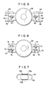
- Figs. 6-7 illustrate the second embodiment of the present invention.
- stepping motor 58 has securing portions 70 which are wider than those of the stepping motor of the first embodiment.
- Elongated hole 72, into which setscrew 74 is inserted, and elongated guide hole 76 are formed in each securing portion 70.
- Guide projection 78 which is integral with frame 76, extends at the location corresponding to each guide hole 76.
- Guide projections 78 are formed simultaneously when frame 76 is die-cast. They are circular at the time of die-casting frame 76, as indicated by "78a" in Fig. 7.
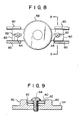
- Figs. 8 and 9 illustrate the third embodiment of the present invention.
- This embodiment is similar to the first embodiment shown in Figs. 3-5, except that opposing guide surfaces 82 of guide portions 80 are slanted such that the distance between two guide surfaces 82 is decreased toward the base.
- setscrews 64 are threadedly inserted into the tapped holes by slightly turning them, the side edges of securing portions 60 are brought into slight contact with guide surfaces 82, completely eliminating the the unnecessary play between guide surfaces 82 and securing portions 60. Under this condition, stepping motor 58 is moved for adjustment, and then setscrews 64 are fastened completely. This embodiment is effective in making a very accurate adjustment.
Abstract
Description
- The present invention relates to a construction for installing the stepping motor of a floppy disk drive unit to a frame, and more particularly, to a construction for enabling the stepping motor to be installed with ease and high accuracy.
- A conventional construction for installing the stepping motor of a floppy disk drive unit is shown in Fig. 1, in which
reference numerals motor 16.Steel belt 12 is wound aroundpulley 14, and the ends ofsteel belt 12 are secured tocarriage 10. Securingportion 18 projects from each side of steppingmotor 16. An elongated hole, which extends in a perpendicular direction to the rotating shaft, is provided in eachsecuring portion 18. Setscrew 22 is inserted intoelongated hole 22 and is threadedly fitted into a tapped hole formed in the frame. - In the floppy disk drive unit described above, stepping
motor 16 must be moved such thatcarriage 10 is accurately positioned with reference to the predetermined position of the disk, so as to ensure compatibility among different disks. Conventionally, this positional adjustment has been made in the following manner. First, steppingmotor 16 is temporarily secured to the frame of the floppy disk drive unit, in the state wheresetscrew 20 is not fastened. Next,carriage 10 is coupled to steppingmotor 16 by use ofpulley 14 andsteel belt 12. Thereafter, steppingmotor 16 is excited such that the rotational angle of the rotating shaft corresponds to the angle determined by the reference position of a disk used for position adjustment, thereby magnetically fixing the rotating shaft at the position determined by the reference rotational angle. Under this condition, the position of a magnetic head provided oncarriage 10 is adjusted to the reference position of the disk used for position adjustment. More specifically, steppingmotor 16 is moved in the direction indicated byarrow 24 in Fig. 1, i.e., parallel tosteel belt 12, while simultaneously permitting the magnetic head to read the data stored in the disk. At this time,carriage 10 moves together with steppingmotor 16, so that the magnetic head moves on the disk. After the magnetic head is moved to the position corresponding to the reference position of the disk,setscrew 20 is fastened, thus completing the position adjustment between steppingmotor 16 andcarriage 10. - When fastening
setscrew 20, torque may be applied to steppingmotor 16, so that steppingmotor 16 may rotate in a horizontal plane. When this happens, however,steel belt 12 is twisted slightly, so that the accuracy of the adjustment is not siginificantly affected. For this reason,conventional stepping motor 16 is not provided with a guide member for guiding the movement of steppingmotor 16 in the direction ofarrow 24. - With the recent miniaturization in floppy disk drive units, smaller stepping motors have been developed. Fig. 2 illustrates a conventional construction for installing such small stepping motors. Referring to Fig. 2, stepping
motor 38 is disk-shaped. Securingportion 40 of steppingmotor 38 is located in a plane perpendicular to the rotating shaft ofmotor 38. Pulley 36 is attached to the end of the rotating shaft.Steel belt 32 is wound aroundpulley 36, and the ends ofsteel belt 32 are secured to the side wall ofcarriage 30. An arcuately elongated hole is provided in each securingportion 40 such that the center of the arcs is located at the rotating shaft. Setscrew 46 is inserted inelongated hole 42 and is threadedly fitted into a tapped hole formed inframe 34.Circular projection 39 is formed at the foot of the rotating shaft of steppingmotor 38. Steppingmotor 38 is positioned byfitting projection 39 into a hole formed inframe 34. - When installing the small stepping motor mentioned above, adjustment is made in the following fashion. First, stepping
motor 38 is temporarily secured to the frame of the floppy disk drive unit, in the state wheresetscrew 46 is not fastened. Next,carriage 30 is coupled to steppingmotor 38 by use ofpulley 36 andsteel belt 22. Thereafter, steppingmotor 38 is excited such that the rotational angle of the rotating shaft corresponds to the angle determined by the reference position of a disk used for position adjustment, thereby magnetically fixing the rotating shaft at the position determined by the reference rotational angle. Under this condition, the position of a magnetic head provided forcarriage 30 is adjusted to the reference position of the disk used for position adjustment. More specifically, steppingmotor 38 is rotated in the direction indicated byarrow 48 in Fig. 2, while simultaneously permitting the magnetic head to read the data stored in the disk. With rotation of steppingmotor 38,carriage 30 moves linearly, so that the magnetic head provided forcarriage 30 also moves on the disk. After the magnetic head is moved to the position corresponding to the reference position of the disk,setscrew 46 is fastened, thus completing the position adjustment between steppingmotor 38 andcarriage 30. - When fastening
setscrews 46, however, torque may be applied to the stepping motor, due to the friction between the screws and the securing portions, so that steppingmotor 38 is apt to be shifted from the reference position. Therefore, steppingmotor 38 cannot be always adjusted with high accuracy when it is installed. If the rotating shaft of steppingmotor 38 is moved 1.0{,carriage 30 will move by the distance corresponding to one pitch of the tracks on the floppy disk. As can be seen from this, the adjustment is significantly affected even if steppingmotor 38 is shifted only slightly from the reference position. - One object of the present invention is to provide a stepping motor-installing construction which enables adjustment to be made with high accuracy, even when a small stepping motor is installed.
- Another object of the present invention is to provide a stepping motor-installing construction which enables a stepping motor to be installed with ease and high accuracy even by an unskilled person.
- The above objects are achieved by providing a guide member which linearly guides the securing portion of a small stepping motor in parallel to the steel belt. If such a guide member is provided, the stepping motor is allowed to move only linearly, so that it is prevented from rotating, inspite of the torque which may be applied to the stepping motor when the setscrews are fastened. As a result, the adjustment can be made with high accuracy. Further, when the setscrews are fastened, the stepping motor need not be fixed by means of a jig or the like. Therefore, the stepping motor can be installed or adjusted with ease and high accuracy even by an unskilled person.
- In the preferred embodiments of the present invention, the guide member is formed integrally with a die-cast frame such that it projects from the frame. The guide member is brought into sliding contact with the side walls of the securing portion of the stepping motor, thus guiding the securing portion.
- The above and other objects of the present invention will become more apparent in the following descriptions and the accompanying drawings in which:
- Fig. 1 is a perspective view illustrating a conventional construction used for installing a stepping motor;
- Fig. 2 is a perspective view illustrating a conventional construction used for installing a small stepping motor;
- Fig. 3 is a perspective view illustrating the upper portion of a construction according to the first embodiment of the present invention, the construction being used for installing a small stepping motor;
- Fig. 4 is a perspective view illustrating the lower portion of the construction shown in Fig. 3;
- Fig. 5 is a view illustrating the bottom of the construction shown in Fig. 3;
- Fig. 6 is a view illustrating the bottom of a construction according to the second embodiment of the present invention;
- Fig. 7 is an enlarged view of the guiding hole provided in the construction shown in Fig. 6;
- Fig. 8 is a view illustrating the bottom of a construction according to the third embodiment of the present invention; and
- Fig. 9 is a sectional view, taken along line 9-9 in Fig. 8.
- Figs. 3-5 show the first embodiment of the present invention. In these Figures,
reference numeral 58 denotes a small stepping motor. Steppingmotor 58 is thin and disk-shaped. It is attached to the lower surface offrame 54, which is die-cast and formed of an aluminum alloy. The rotating shaft of the stepping motor passes throughframe 54 and extends upward from the upper surface offrame 54.Pulley 56 is attached to the rotating shaft, andsteel belt 52 is wound aroundpulley 56.Steel belt 52 is secured, at both ends, to the side wall ofcarriage 50. A pair of securingportions 60 project from the upper edge of the circumferential wall of steppingmotor 58, in the radial direction of steppingmotor 58. Securingportions 60 are formed like a plate, and linearlyelongated hole 62 is provided in each of securingportions 60.Holes 62 are formed such that they extend along a line passing through the center of the stepping motor and in parallel tosteel belt 52.Setscrew 64 is inserted intohole 62 and is threadedly fitted into the tapped hole formed inframe 54. -
Guide portions 66, which are integral withframe 54, project from the lower side offrame 54.Guide portions 66 have a substantially rectangular cross section and are located such that they are almost in contact with the respective side edges of securingportions 60. More specifically, there is a small gap between the side edges of securingportions 60 and the corresponding faces ofguide portions 66. At the time of installing steppingmotor 58, securingportions 60 are guided or restricted in movement byguide portions 66, so that steppingmotor 58 is permited to move only parallel tosteel belt 52, thus preventing steppingmotor 58 from rotating. - In this embodiment, installation and adjustment of stepping
motor 58 are performed in the following manner: First, steppingmotor 58 is temporarily secured to the frame of the floppy disk drive unit, in the state wheresetscrew 64 is not fastened. Next,carriage 50 is coupled to steppingmotor 58 by use ofpulley 56 andsteel belt 52. Thereafter, steppingmotor 58 is excited such that the rotational angle of the rotating shaft corresponds to the angle determined by the reference position of a disk used for position adjustment, thereby magnetically fixing the rotating shaft at the position determined by the reference rotational angle. Under this condition, the position of a magnetic head provided forcarriage 50 is adjusted to the reference position of the disk used for position adjustment. More specifically, steppingmotor 58 is moved in the direction indicated byarrow 68 in Fig. 3, i.e., parallel tosteel belt 52, while simultaneously permitting the magnetic head to read the data stored in the disk. At this time,carriage 50 moves together with steppingmotor 58, so that the magnetic head moves on the disk. After the magnetic head is moved to the position corresponding to the reference position of the disk,setscrew 64 is fastened, thus completing the position adjustment between steppingmotor 58 andcarriage 50. - When setscrews 64 are fastened, torque may be applied to stepping
motor 58, due to the friction between securingportions 60 and the head ofsetscrews 64. Even if such torque is applied, guideportions 66 prevent rotation of steppingmotor 58. Therefore, accurate adjustment of steppingmotor 58 can be made with ease. Such accurate adjustment is possible, even by an unskilled person. - Figs. 6-7 illustrate the second embodiment of the present invention. In this embodiment, stepping
motor 58 has securingportions 70 which are wider than those of the stepping motor of the first embodiment.Elongated hole 72, into whichsetscrew 74 is inserted, andelongated guide hole 76 are formed in each securingportion 70.Guide projection 78, which is integral withframe 76, extends at the location corresponding to eachguide hole 76.Guide projections 78 are formed simultaneously whenframe 76 is die-cast. They are circular at the time of die-casting frame 76, as indicated by "78a" in Fig. 7. After formingframe 76 by die casting, the circumferential walls ofprojection 78 are subjected to cutting, thereby providing smooth guide surfaces 78b and 78c with high precision. Guide surfaces 78b and 78c thus obtained face the corresponding inner surfaces of guide holes 76 with a very small gap therebetween, thus guiding securingportions 70 reliably and accurately. - Figs. 8 and 9 illustrate the third embodiment of the present invention. This embodiment is similar to the first embodiment shown in Figs. 3-5, except that opposing guide surfaces 82 of
guide portions 80 are slanted such that the distance between two guide surfaces 82 is decreased toward the base. In this embodiment, ifsetscrews 64 are threadedly inserted into the tapped holes by slightly turning them, the side edges of securingportions 60 are brought into slight contact with guide surfaces 82, completely eliminating the the unnecessary play between guide surfaces 82 and securingportions 60. Under this condition, steppingmotor 58 is moved for adjustment, and then setscrews 64 are fastened completely. This embodiment is effective in making a very accurate adjustment. - The present invention is not limited to the above embodiments. It is obvious that those skilled in the art could easily modify or improve the present invention without departing from the spirit of the invention.
Claims (5)
characterized in that:
the securing portion (60) is provided with an elongated installation hole (62) extending parallel to the steel belt (52);
the frame (54) is provided with a guide member (66) for guiding the securing portion (60) only in a direction parallel to the steel belt; and
a setscrew (64) is inserted into the installation hole (62) and is threadedly fitted into a tapped hole provided in the frame (54).
Applications Claiming Priority (2)
| Application Number | Priority Date | Filing Date | Title |
|---|---|---|---|
| JP269662/85 | 1985-11-30 | ||
| JP60269662A JPS62129977A (en) | 1985-11-30 | 1985-11-30 | Floppy disk device |
Publications (3)
| Publication Number | Publication Date |
|---|---|
| EP0224852A2 true EP0224852A2 (en) | 1987-06-10 |
| EP0224852A3 EP0224852A3 (en) | 1988-07-06 |
| EP0224852B1 EP0224852B1 (en) | 1991-07-03 |
Family
ID=17475467
Family Applications (1)
| Application Number | Title | Priority Date | Filing Date |
|---|---|---|---|
| EP86116356A Expired - Lifetime EP0224852B1 (en) | 1985-11-30 | 1986-11-25 | Construction for installing a stepping motor of a floppy disk drive unit |
Country Status (5)
| Country | Link |
|---|---|
| US (1) | US4700095A (en) |
| EP (1) | EP0224852B1 (en) |
| JP (1) | JPS62129977A (en) |
| KR (1) | KR900003693B1 (en) |
| DE (1) | DE3680076D1 (en) |
Cited By (1)
| Publication number | Priority date | Publication date | Assignee | Title |
|---|---|---|---|---|
| DE4102213A1 (en) * | 1990-01-25 | 1991-08-01 | Asahi Optical Co Ltd | DEVICE FOR ADJUSTING THE POSITION OF AN ELEMENT |
Families Citing this family (9)
| Publication number | Priority date | Publication date | Assignee | Title |
|---|---|---|---|---|
| US5102090A (en) * | 1991-05-02 | 1992-04-07 | General Motors Corporation | Power window motor mounting bracket |
| JP2776698B2 (en) * | 1992-08-17 | 1998-07-16 | 日本電気株式会社 | Drive section of floppy disk drive |
| JP2005110489A (en) * | 2003-09-08 | 2005-04-21 | Asmo Co Ltd | Holding structure of motor and motor actuator |
| US20070251555A1 (en) * | 2004-09-16 | 2007-11-01 | Lg Electronics, Inc. | Dishwasher |
| KR100617157B1 (en) * | 2004-09-16 | 2006-08-31 | 엘지전자 주식회사 | Mounting structure for washing-motor in dishwashing machine |
| KR20060035086A (en) * | 2004-10-21 | 2006-04-26 | 엘지전자 주식회사 | Dish washer |
| JP4360424B2 (en) * | 2007-06-06 | 2009-11-11 | ブラザー工業株式会社 | Driving force transmission mechanism, image forming apparatus and method of assembling the same |
| USD728722S1 (en) | 2013-04-29 | 2015-05-05 | Ashbury International Group, Inc. | Forend for modular tactical firearms |
| USD728723S1 (en) | 2013-04-29 | 2015-05-05 | Ashbury International Group, Inc. | Forend for modular tactical firearms |
Citations (4)
| Publication number | Priority date | Publication date | Assignee | Title |
|---|---|---|---|---|
| US3881189A (en) * | 1972-09-07 | 1975-04-29 | Sanyo Electric Co | Transducer arrangement in recording and/or playback devices utilizing disc records |
| DE2812981A1 (en) * | 1977-04-05 | 1978-10-12 | Shugart Associates | POSITIONING MECHANISM FOR MAGNETIC DISK MEMORY |
| EP0085970A2 (en) * | 1982-02-05 | 1983-08-17 | Forestlane Co., Ltd. | Positioning mechanism for a floppy disk drive read/write head carriage |
| GB2141865A (en) * | 1983-06-13 | 1985-01-03 | Alps Electric Co Ltd | Carriage drive unit |
Family Cites Families (1)
| Publication number | Priority date | Publication date | Assignee | Title |
|---|---|---|---|---|
| US4227101A (en) * | 1978-06-05 | 1980-10-07 | Transicoil, Inc. | Stepper motor and adaptor ring |
-
1985
- 1985-11-30 JP JP60269662A patent/JPS62129977A/en active Pending
-
1986
- 1986-11-25 EP EP86116356A patent/EP0224852B1/en not_active Expired - Lifetime
- 1986-11-25 DE DE8686116356T patent/DE3680076D1/en not_active Expired - Lifetime
- 1986-11-26 US US06/935,223 patent/US4700095A/en not_active Expired - Fee Related
- 1986-11-29 KR KR8610161A patent/KR900003693B1/en not_active IP Right Cessation
Patent Citations (4)
| Publication number | Priority date | Publication date | Assignee | Title |
|---|---|---|---|---|
| US3881189A (en) * | 1972-09-07 | 1975-04-29 | Sanyo Electric Co | Transducer arrangement in recording and/or playback devices utilizing disc records |
| DE2812981A1 (en) * | 1977-04-05 | 1978-10-12 | Shugart Associates | POSITIONING MECHANISM FOR MAGNETIC DISK MEMORY |
| EP0085970A2 (en) * | 1982-02-05 | 1983-08-17 | Forestlane Co., Ltd. | Positioning mechanism for a floppy disk drive read/write head carriage |
| GB2141865A (en) * | 1983-06-13 | 1985-01-03 | Alps Electric Co Ltd | Carriage drive unit |
Cited By (2)
| Publication number | Priority date | Publication date | Assignee | Title |
|---|---|---|---|---|
| DE4102213A1 (en) * | 1990-01-25 | 1991-08-01 | Asahi Optical Co Ltd | DEVICE FOR ADJUSTING THE POSITION OF AN ELEMENT |
| US5307703A (en) * | 1990-01-25 | 1994-05-03 | Asahi Kogaku Kogyo Kabushiki Kaisha | Head adjusting device |
Also Published As
| Publication number | Publication date |
|---|---|
| DE3680076D1 (en) | 1991-08-08 |
| US4700095A (en) | 1987-10-13 |
| EP0224852A3 (en) | 1988-07-06 |
| KR900003693B1 (en) | 1990-05-30 |
| EP0224852B1 (en) | 1991-07-03 |
| KR870005372A (en) | 1987-06-08 |
| JPS62129977A (en) | 1987-06-12 |
Similar Documents
| Publication | Publication Date | Title |
|---|---|---|
| US4700095A (en) | Construction for installing a stepping motor of a floppy disk drive unit | |
| EP0273620B1 (en) | Rotary magnetic head devices | |
| US5363260A (en) | Magnetic disk apparatus and method for manufacturing the same | |
| US6477001B1 (en) | Disk drive apparatus having improved auto-balancing unit | |
| US4725910A (en) | Rotary magnetic head assembly | |
| EP0661705A2 (en) | Tape drive and cassette with precise registration | |
| US6770998B2 (en) | Inner-rotor motor implementing rotor with effective drive, and disk drive using the same | |
| US20020089246A1 (en) | Thin inner rotor motor for rotatably driving medium, and disk apparatus using the same | |
| US6713926B2 (en) | Thin and lightweight inner rotor motor and disk unit using the same | |
| EP0239139B1 (en) | Magnetic-tape apparatus comprising a scanning unit and method of manufacturing such a scanning unit | |
| US5032941A (en) | Magnetic head feeding device | |
| JP3569331B2 (en) | Tape running device | |
| JP2643642B2 (en) | Motor positioning method | |
| EP0661704A2 (en) | High speed tape transport cassette | |
| JP2565295B2 (en) | Spindle motor of disk device | |
| US6747839B2 (en) | Magnetic recording/reproducing device having a post stopper fixed to a vertical reinforcing wall | |
| KR840002639Y1 (en) | Guide post of video tape recoder | |
| US4617514A (en) | Disk and gear mounting in electric watthour meter | |
| JPS59104754A (en) | Positioning device of tape leader | |
| JPS6225859A (en) | Flat type brushless motor | |
| KR890005448Y1 (en) | Moving device of signal exchanger | |
| JPH0725884Y2 (en) | Tape pull-out member positioning device | |
| KR890005447Y1 (en) | Moving device signal exchanger | |
| JP2516160Y2 (en) | Drive device | |
| JPS59117454A (en) | Stator positioning structure |
Legal Events
| Date | Code | Title | Description |
|---|---|---|---|
| PUAI | Public reference made under article 153(3) epc to a published international application that has entered the european phase |
Free format text: ORIGINAL CODE: 0009012 |
|
| 17P | Request for examination filed |
Effective date: 19861222 |
|
| AK | Designated contracting states |
Kind code of ref document: A2 Designated state(s): DE FR GB IT |
|
| PUAL | Search report despatched |
Free format text: ORIGINAL CODE: 0009013 |
|
| AK | Designated contracting states |
Kind code of ref document: A3 Designated state(s): DE FR GB IT |
|
| 17Q | First examination report despatched |
Effective date: 19891201 |
|
| GRAA | (expected) grant |
Free format text: ORIGINAL CODE: 0009210 |
|
| AK | Designated contracting states |
Kind code of ref document: B1 Designated state(s): DE FR GB IT |
|
| ITF | It: translation for a ep patent filed |
Owner name: JACOBACCI & PERANI S.P.A. |
|
| REF | Corresponds to: |
Ref document number: 3680076 Country of ref document: DE Date of ref document: 19910808 |
|
| ET | Fr: translation filed | ||
| PLBE | No opposition filed within time limit |
Free format text: ORIGINAL CODE: 0009261 |
|
| STAA | Information on the status of an ep patent application or granted ep patent |
Free format text: STATUS: NO OPPOSITION FILED WITHIN TIME LIMIT |
|
| 26N | No opposition filed | ||
| PGFP | Annual fee paid to national office [announced via postgrant information from national office to epo] |
Ref country code: FR Payment date: 19951109 Year of fee payment: 10 |
|
| PGFP | Annual fee paid to national office [announced via postgrant information from national office to epo] |
Ref country code: GB Payment date: 19951116 Year of fee payment: 10 |
|
| PGFP | Annual fee paid to national office [announced via postgrant information from national office to epo] |
Ref country code: DE Payment date: 19951128 Year of fee payment: 10 |
|
| PG25 | Lapsed in a contracting state [announced via postgrant information from national office to epo] |
Ref country code: GB Effective date: 19961125 |
|
| GBPC | Gb: european patent ceased through non-payment of renewal fee |
Effective date: 19961125 |
|
| PG25 | Lapsed in a contracting state [announced via postgrant information from national office to epo] |
Ref country code: FR Effective date: 19970731 |
|
| PG25 | Lapsed in a contracting state [announced via postgrant information from national office to epo] |
Ref country code: DE Effective date: 19970801 |
|
| REG | Reference to a national code |
Ref country code: FR Ref legal event code: ST |
|
| PG25 | Lapsed in a contracting state [announced via postgrant information from national office to epo] |
Ref country code: IT Free format text: LAPSE BECAUSE OF NON-PAYMENT OF DUE FEES;WARNING: LAPSES OF ITALIAN PATENTS WITH EFFECTIVE DATE BEFORE 2007 MAY HAVE OCCURRED AT ANY TIME BEFORE 2007. THE CORRECT EFFECTIVE DATE MAY BE DIFFERENT FROM THE ONE RECORDED. Effective date: 20051125 |