EP0223597A2 - Buffer compensation in enzyme - modified ion sensitive devices - Google Patents
Buffer compensation in enzyme - modified ion sensitive devices Download PDFInfo
- Publication number
- EP0223597A2 EP0223597A2 EP86309003A EP86309003A EP0223597A2 EP 0223597 A2 EP0223597 A2 EP 0223597A2 EP 86309003 A EP86309003 A EP 86309003A EP 86309003 A EP86309003 A EP 86309003A EP 0223597 A2 EP0223597 A2 EP 0223597A2
- Authority
- EP
- European Patent Office
- Prior art keywords
- enzyme
- ion
- concentration
- substance
- ions
- Prior art date
- Legal status (The legal status is an assumption and is not a legal conclusion. Google has not performed a legal analysis and makes no representation as to the accuracy of the status listed.)
- Granted
Links
Images


Classifications
-
- C—CHEMISTRY; METALLURGY
- C12—BIOCHEMISTRY; BEER; SPIRITS; WINE; VINEGAR; MICROBIOLOGY; ENZYMOLOGY; MUTATION OR GENETIC ENGINEERING
- C12Q—MEASURING OR TESTING PROCESSES INVOLVING ENZYMES, NUCLEIC ACIDS OR MICROORGANISMS; COMPOSITIONS OR TEST PAPERS THEREFOR; PROCESSES OF PREPARING SUCH COMPOSITIONS; CONDITION-RESPONSIVE CONTROL IN MICROBIOLOGICAL OR ENZYMOLOGICAL PROCESSES
- C12Q1/00—Measuring or testing processes involving enzymes, nucleic acids or microorganisms; Compositions therefor; Processes of preparing such compositions
- C12Q1/001—Enzyme electrodes
-
- G—PHYSICS
- G01—MEASURING; TESTING
- G01N—INVESTIGATING OR ANALYSING MATERIALS BY DETERMINING THEIR CHEMICAL OR PHYSICAL PROPERTIES
- G01N27/00—Investigating or analysing materials by the use of electric, electrochemical, or magnetic means
- G01N27/26—Investigating or analysing materials by the use of electric, electrochemical, or magnetic means by investigating electrochemical variables; by using electrolysis or electrophoresis
- G01N27/403—Cells and electrode assemblies
- G01N27/414—Ion-sensitive or chemical field-effect transistors, i.e. ISFETS or CHEMFETS
- G01N27/4145—Ion-sensitive or chemical field-effect transistors, i.e. ISFETS or CHEMFETS specially adapted for biomolecules, e.g. gate electrode with immobilised receptors
Definitions
- This invention is related to a system and method for measuring the concentration of a substance in a solution, useful when the solution contains a buffer. It also relates to a device which may be used in such a system.
- the invention applies to the use of ion-sensitive devices and in particular to enzyme-modified ion sensitive devices.
- ENFET enzyme-modified ion sensitive field effect transistor
- An ENFET (shown schematically in Figure 1) is an ion-sensitive device consisting of a semiconductor substrate 1, with source and drain regions 2 and 3 respectively diffused into it. Metal conductors 5 and 6 provide electrical connections to the source and drain. An ion-sensitive layer 7 is insulated from the channel between the source and drain by insulating material 4. This layer is overlaid by a thin film layer or membrane 8 and the device is encapsulated by layer 9.
- the ENFET may be placed in contact with a solution 10 which is to be analysed. If a reference electrode 11 is placed in the solution, the electrical potential across the reference electrode/solution interface is constant.
- the device can detect the concentration of the enzyme's substrate in the solution with which the enzyme may react, by virtue of the fact that the enzyme will produce, for example, a certain number of ions to which the ion-selective layer is sensitive, for each mole of the substrate it reacts with and the potential across the ion-selective layer/membrane interface varies accordingly. Conversely, the substrate upon which an enzyme will act may be immobilized in layer 8 and the concentration of the corresponding enzyme can then be detected.
- a device is described in fuller detail in Patent No. GB 1529743.
- the hydrogen (H ) ions may be detected by a pH sensitive layer.
- the measured potential is a function of the difference between the logarithms of the bulk solution and surface pH values such that the differential potential is also a function of bulk solution pH.
- the detected pH does not change in simple relation to the enzyme's substrate concentration.
- a system suitable for measuring the concentration of a first substance in a solution which contains ions comprising two ion sensitive devices, each device incorporating means sensitive to said ions and one of said devices further incorporating a second substance which causes additional said ions to be produced when said second substance is exposed to said first substance and each device having an output response related to a concentration of ions sensed by the ion-sensitive means, said output responses having a predetermined relationship to each other whenever the concentrations of said ions detected by the two devices are substantially equal; and an electrical control circuit for controlling the concentration of ions detected by one or the other of said devices, thereby enabling their responses to attain said predetermined relationship, and for generating an electrical signal which is indicative of said concentration of said first substance whenever said predetermined relationship is attained.
- the second substance could be an enzyme suitable for use in the measurement of the concentration of a corresponding enzyme substrate, or vice versa.
- the ion sensitive devices may be ISFETs, said one device being an enzyme - modified ISFET.
- the electrical control circuit includes a comparison circuit for measuring a difference between the two responses to produce a comparison signal, the comparison signal being used to effect the control of ion concentration.
- the system may include a titrating electrode and a counter electrode wherein the comparison signal is used to control a current via the two electrodes thereby to effect the control of ion concentration.
- the current passed may create a change in ion concentration to essentially match or cancel the change in ion concentration produced by the action of the enzyme.
- the ions generated are preferably H + ions, in which case the ion-sensitive devices, for example an ENFET and an ISFET, are pH sensitive, the diffusional flux of the substrate generates a local proton concentration change in the enzyme layer, and the pH values at the ion sensitive layers of the ENFET and ISFET are maintained essentially equal.
- the titrating electrode may be at the gate of the ENFET and may surround the gate of the ENFET.
- the titrating current may be passed to keep the pH value at the ion-sensitive layer of the ENFET essentially constant.
- the titrating electrode may be at the gate of the ISFET, in which case the titrating current is passed to create an ion or pH change equal to that caused by enzyme action at the ENFET, so that the potential responses of the two devices are matched.
- the current is related to the change in ion concentration or pH brought about by enzyme action.
- the potential response and hence ion concentration (or pH value) at the ion-sensitive layer of the devices may be measured by circuit means such as that described in "Chemical-sensitive field effect transistors" (Sibbald, A., IEE Proceedings, Vol. 130., Pt. 1, No. 5, October 1983) with reference to Fig. 6 of this paper. That is, for each device the source-drain current (which is dependent upon the potential across the conducting channel) may be measured, or alternatively the source-drain current may be maintained at a constant value by means of a simple feedback loop, so that changes in potential across the device may be measured directly.
- an ion-sensitive device having a titrating electrode.
- a method suitable for determining the concentration of a first substance in a solution containing ions including generating additional said ions by the interaction of said first substance and a second substance to produce a change in ion concentration at a test location, the number of ions generated being related to the concentration of said first substance; comparing the concentration of ions at a reference location with that at the test location and modifying the ion concentration at one of said locations to cause substantial equality of ion concentration at said locations, the extent of the modification being related to the concentration of said first substance in the solution.
- FIG 2A represents a possible construction of an ENFET with a titrating electrode, for use in the invention.
- the construction is similar to the known ENFET shown in Figure 1, in that it is built on a substrate 1, and an ion sensitive layer 7 is provided over an insulating layer 4. However, adjacent to the enzyme layer 8, there is a titrating electrode 12.
- the electrode may be in the form of a suspended mesh.
- the titrating electrode 12 may be adjacent and surrounding the ion-sensitive gate material 7 of the FET as shown in Figure 2B.
- An ISFET with an enzyme substrate layer may also have a titrating electrode and be of similar construction to the ENFET device of Figure 2A.
- the concentration of H + ions can be maintained by consuming H + ions generated due to the enzyme action before they can reach the bulk solution or the ion-(or pH-) sensitive layer.
- the host ISFET device of the ENFET senses[H + ]via a change in potential. If this potential were to act in a feedback loop containing the titrating electrode, the [H + ]as reflected by the potential could be kept constant. In order to maintain the [H + ]constant, a titrating current equivalent to the perturbation produced by the enzyme (i.e. n moles of electrons) must be supplied. This would restore the original pH/buffer balance. (This is the feedback loop mode, and in fact the system is never shifted out of equilibrium.)
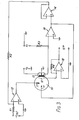
- Figure 3 represents a "titrating" circuit considered to be suitable for implementing the invention.
- Device 13 is preferably an enzyme-modified pH-sensitive FET (pH-ENFET), having a titrating electrode 12 associated with it.
- Device 13 is placed in contact with a solution 10 (the analyte), the solution containing the enzyme's substrate, the concentration of which it is desired to determine.
- a pH-sensitive FET (pH-ISFET) (not shown in Figure 3), which is similar in all essential respects to the pH-ENFET shown except that it has no enzyme layer, is placed in contact with the same solution.
- E ref the gate potential of the pH-ISFET, may be applied as shown in Figure 3.
- V sub is the potential of the semiconductor substrate and E i is the potential at the surface of the insulator adjacent to the ion-(or pH-) sensitive layer, then to keep the source-drain current i D constant, the potential across the conducting channel (V sub -E i ) must be kept constant.
- i D is set using V and V D as shown.
- V D is the drain voltage.
- the output of 16 is fed to the reference electrode, so RE and E ref must be set equal.
- the circuit will measure the difference between RE and the substrate voltage for the pH-ENFET.
- ⁇ E m is the potential due to hydrogen ions
- R is the gas constant
- T is the temperature
- F is the Faraday constant
- [H + ] enz is the concentration of H + ions at the surface of the ion-sensitive layer in the ENFET.
- reference pH-ISFET (bars denote reference pH-ISFET) where is the concentration of H + ions in the bulk solution, indicated by the pH of the bulk solution which may be measured.
- the constants C and C' vary depending on the situation and the calibration may be adjusted so that they are equal or they may be trimmed to zero.
- the titrating part of the circuit should be allowed to float with respect to the rest of the circuit and the earths of the two operational amplifiers 15 and 18 should be common, but different from the other earths in the circuit which should be common to each other.
- V sub- RE # E ref due to the enzyme altering the local hydrogen ion concentration from the hydrogen ion concentration in the bulk solution
- the potential at the negative input of operational amplifier 15 is not a virtual earth.
- Amplifier 15 therefore outputs a current which flows through the counter electrode 17.
- the counter electrode may be made from a noble metal e.g. platinum gauze).
- the current cannot flow to the ENFET itself (since the ENFET gate is an insulator) and it cannot flow to the reference electrode since this is connected to the input of operational amplifier 14.
- the current therefore flows through the titrating electrode to a virtual earth input of operational amplifier 18 (which is a current-voltage converter) and through resistor R4 to the output o/p of 18.
- the voltage output of amplifier 18 is proportional to the titrating current and hence to the concentration of substrate upon which the enzyme acts.
- the problems associated with the prior art of the protons diffusing away, reacting again to form the substrate or reacting with buffer, prior to detection, can be compensated for.
- the device 13 in Figure 3 is a "dummy" pH-ENFET, a pH-ISFET which has a titrating electrode associated with it.
- the pH-sensitive gate material may be covered not with an enzyme layer but with a suitably porous electrode material (the titrating electrode) as in the pH-ENFET device described earlier.
- the titrating electrode may be adjacent and surrounding the ion-sensitive gate material.
- protons may be either generated or destroyed by passing a current via an auxiliary electrode (the counter electrode 17) in the solution.
- the potential response of the "dummy" pH-ENFET may be made to match that of the pH-ENFET by virtue of the controlled current via the titrating electrode, in the feedback circuit.
- the current flowing through the titrating electrode at the "dummy" ENFET gate will be equivalent to the diffusional flux cf the analyte to the conventional pH-ENFET gate. This is because the rate at which H + ions are produced by the enzyme at the conventional pH-ENFET gate depends on the diffusional flux of the analyte to the conventional pH-ENFET gate.
- the ISFET and ENFET or other ion-sensitive devices are not necessarily pH-sensitive as described in the examples above.
- the devices can be made sensitive to other types of ion by using different ion-sensitive layers. If the ions which are generated by the action of the enzyme on the substrate are of valencies other than one (as for hydrogen ions), this must be taken into account when relating the current in the feedback loop to the ion concentration.
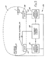
- FIGS 4 and 5 schematically represent different embodiments (19 and 20 respectively) of circuits for determining the concentration of an enzyme's substrate in an analyte solution 21 containing a buffer.
- Each circuit comprises an ISFET 22 and an ENFET 23 in contact with the solution, the ENFET and ISFET being similar in all essential respects except that the ENFET further includes an enzyme layer 24 containing an enzyme which acts on the substrate to generate ions to which the ion-sensitive layers in the ENFET and ISFET are selective.
- ISFET potential measuring circuit 25 measures the potential between the reference electrode ?7 and the semiconductor substrate of the ISFET
- ENFET potential measuring circuit 26 measures the potential between the reference electrode and the semiconductor substrate of the ENFET.
- Feedback control circuit 28 compares these potentials and provides a current proportional to the difference.
- This titrating current flows through the titrating electrode 29 which, in the circuit 19 of Figure 4 is associated with the ENFET, and in the circuit 20 shown in Figure 5 is associated with the ISFET.
- the titrating current i 1 compensates for enzyme-generated ions and in circuit 20, the titrating current i 2 generates an ion concentration matching that of the ENFET.
- the titrating current is essentially equivalent to the diffusional flux of the enzyme's substrate to the ENFET and hence is proportional to the concentration of the enzyme's substrate in the analyte solution.
- the invention is particularly useful when the devices are pH-sensitive. Also, the materials used for the insulating layers in ISFETs are often pH-sensitive and it is not necessary to include a further pH-seleetive membrane.
- the invention can be used to detect the concentration of the enzyme in a solution, rather than the concentration of its substrate.
- the invention also encompasses use of ion-sensitive devices other than ion sensitive FETs, for example ion-selective electrodes (ISEs), metal/metal oxide pH sensors, and other metal/metal salt ion sensors.
- ISEs ion-selective electrodes
- metal/metal oxide pH sensors metal/metal oxide pH sensors
- metal/metal salt ion sensors other metal/metal salt ion sensors.
Abstract
Description
- This invention is related to a system and method for measuring the concentration of a substance in a solution, useful when the solution contains a buffer. It also relates to a device which may be used in such a system. The invention applies to the use of ion-sensitive devices and in particular to enzyme-modified ion sensitive devices.
- The structure and operation of the ENFET (enzyme-modified ion sensitive field effect transistor) is well known (see for example Caras, S. and Janata, J., Anal. Chem. 1980, 52, pp. 1935-1937 and Miyahara, Y. et ,al., Analytical Chemistry Symposia Series, 17 (1983)) and may be summarised as follows:
- An ENFET (shown schematically in Figure 1) is an ion-sensitive device consisting of a
semiconductor substrate 1, with source anddrain regions 2 and 3 respectively diffused into it.Metal conductors 5 and 6 provide electrical connections to the source and drain. An ion-sensitive layer 7 is insulated from the channel between the source and drain by insulatingmaterial 4. This layer is overlaid by a thin film layer ormembrane 8 and the device is encapsulated bylayer 9. The ENFET may be placed in contact with asolution 10 which is to be analysed. If areference electrode 11 is placed in the solution, the electrical potential across the reference electrode/solution interface is constant. If themembrane 8 has an enzyme immobilized in it, the device can detect the concentration of the enzyme's substrate in the solution with which the enzyme may react, by virtue of the fact that the enzyme will produce, for example, a certain number of ions to which the ion-selective layer is sensitive, for each mole of the substrate it reacts with and the potential across the ion-selective layer/membrane interface varies accordingly. Conversely, the substrate upon which an enzyme will act may be immobilized inlayer 8 and the concentration of the corresponding enzyme can then be detected. Such a device is described in fuller detail in Patent No. GB 1529743. - Taking as an example the case when an enzyme acts on its substrate to give an acid,
-

- It is known to take two ISFETs (see Caras and Janata), one with and one without an enzyme layer, and compare the two responses by placing them in the same solution and connecting them in the differential mode. Since the device having the enzyme layer will, for example as in the above case, generate protons in the presence of the enzyme's substrate and the other device will not, a comparison of their responses reflects the number of protons generated from the substrate. This differential mode of measurement will automatically compensate to some extent for changes in ambient solution conditions since. such changes affect the enzyme-modified and reference ISFETs equally, provided that the temperature and pH characteristics of each device are the same.
- Problems arise however when the above arrangements are used with solutions which have buffering capacity, such as clinical and other samples, (see for example Eddowes M.J., Sensors and Actuators 7(1985) 97-115, Eddowes et al., Sensors and Actuators 7 (1985)233-244 and Caras et al. Anal. Chem. 57(1985) 1917-1925). In this case, the sensitivity of the device to the enzyme's substrate will be reduced by an indeterminate amount. If, for example, an enzyme acts to produce a certain number of .moles of H+ ions per mole of its substrate, this amount of H+ is not detected by the device because the buffer reacts immediately with some of the H+ ions. Furthermore, in the differential mode, the measured potential is a function of the difference between the logarithms of the bulk solution and surface pH values such that the differential potential is also a function of bulk solution pH. Hence the detected pH does not change in simple relation to the enzyme's substrate concentration.
- In the prior art, solutions of defined buffer capacity and pH have been analysed and it has been shown that ENFETs produce a change in pH great enough to be measured by conventional methods. In this case it is possible to calibrate the response of the device for these specific conditions, but the response is of complicated form and varies with buffer concentration and bulk solution pH.
- It is an object of the invention to alleviate some of the disadvantages, as described above, of the prior art.
- According to the invention there is provided a system suitable for measuring the concentration of a first substance in a solution which contains ions, the system comprising two ion sensitive devices, each device incorporating means sensitive to said ions and one of said devices further incorporating a second substance which causes additional said ions to be produced when said second substance is exposed to said first substance and each device having an output response related to a concentration of ions sensed by the ion-sensitive means, said output responses having a predetermined relationship to each other whenever the concentrations of said ions detected by the two devices are substantially equal; and an electrical control circuit for controlling the concentration of ions detected by one or the other of said devices, thereby enabling their responses to attain said predetermined relationship, and for generating an electrical signal which is indicative of said concentration of said first substance whenever said predetermined relationship is attained.
- The second substance could be an enzyme suitable for use in the measurement of the concentration of a corresponding enzyme substrate, or vice versa. The ion sensitive devices may be ISFETs, said one device being an enzyme - modified ISFET.
- In a particular embodiment of a system, the electrical control circuit includes a comparison circuit for measuring a difference between the two responses to produce a comparison signal, the comparison signal being used to effect the control of ion concentration.
- The system may include a titrating electrode and a counter electrode wherein the comparison signal is used to control a current via the two electrodes thereby to effect the control of ion concentration.
- The current passed may create a change in ion concentration to essentially match or cancel the change in ion concentration produced by the action of the enzyme.
- The ions generated are preferably H+ ions, in which case the ion-sensitive devices, for example an ENFET and an ISFET, are pH sensitive, the diffusional flux of the substrate generates a local proton concentration change in the enzyme layer, and the pH values at the ion sensitive layers of the ENFET and ISFET are maintained essentially equal.
- When the devices used are an ENFET and an ISFET, the titrating electrode may be at the gate of the ENFET and may surround the gate of the ENFET. The titrating current may be passed to keep the pH value at the ion-sensitive layer of the ENFET essentially constant. Alternatively, the titrating electrode may be at the gate of the ISFET, in which case the titrating current is passed to create an ion or pH change equal to that caused by enzyme action at the ENFET, so that the potential responses of the two devices are matched.
- In each of the above cases, the current is related to the change in ion concentration or pH brought about by enzyme action.
- The potential response and hence ion concentration (or pH value) at the ion-sensitive layer of the devices may be measured by circuit means such as that described in "Chemical-sensitive field effect transistors" (Sibbald, A., IEE Proceedings, Vol. 130., Pt. 1, No. 5, October 1983) with reference to Fig. 6 of this paper. That is, for each device the source-drain current (which is dependent upon the potential across the conducting channel) may be measured, or alternatively the source-drain current may be maintained at a constant value by means of a simple feedback loop, so that changes in potential across the device may be measured directly.
- According to a further aspect of the invention there is provided an ion-sensitive device having a titrating electrode.
- According to another aspect of the invention there is provided a method suitable for determining the concentration of a first substance in a solution containing ions, the method including generating additional said ions by the interaction of said first substance and a second substance to produce a change in ion concentration at a test location, the number of ions generated being related to the concentration of said first substance; comparing the concentration of ions at a reference location with that at the test location and modifying the ion concentration at one of said locations to cause substantial equality of ion concentration at said locations, the extent of the modification being related to the concentration of said first substance in the solution.
- In order that the invention may be clearly understood and readily carried into effect, it will be described by way of example with reference to the accompanying drawings of which:
- Figure 1 is a schematic representation of an enzyme - modified ion-sensitive field effect transistor (ENFET) as known in the prior art and as described earlier,
- Figure 2A represents a possible construction of an ENFET having a titrating electrode between the enzyme and ion-sensitive layers,
- Figure 2B represents a possible construction of an ENFET having a titrating electrode surrounding the gate,
- Figure 3 shows a titrating circuit,
- Figure 4 schematically represents a circuit for compensation for enzyme-generated ions, and
- Figure 5 schematically represents a circuit which generates a change in ion concentration to match that produced by an enzyme.
- Figure 2A represents a possible construction of an ENFET with a titrating electrode, for use in the invention. The construction is similar to the known ENFET shown in Figure 1, in that it is built on a
substrate 1, and an ionsensitive layer 7 is provided over aninsulating layer 4. However, adjacent to theenzyme layer 8, there is atitrating electrode 12. The electrode may be in the form of a suspended mesh. Alternatively, thetitrating electrode 12 may be adjacent and surrounding the ion-sensitive gate material 7 of the FET as shown in Figure 2B. (An ISFET with an enzyme substrate layer may also have a titrating electrode and be of similar construction to the ENFET device of Figure 2A.) - Considering the case when the enzyme acts on the substrate to produce protons, when a current is passed through the titrating electrode, electrons are provided which can consume protons generated within the enzyme layer, i.e.


- By use of a feedback circuit, the concentration of H+ ions can be maintained by consuming H+ ions generated due to the enzyme action before they can reach the bulk solution or the ion-(or pH-) sensitive layer.
- It is also possible to supply a current manually to compensate for generated ions.
- Setting out some theory,
if at time t = 0,
there are x moles of H present,
y moles of B present,
n moles of substrate,
and m moles of BH (buffer) in known equilibrium
and if n moles of product (= A-/H+) were then to be generated,
x + n moles of H would then be present.
But H+ may react with B- to form z moles of BH.
(The presence of H+ perturbs the original equilibrium.)
Then there would be
(x + n - z ) moles of H+ (which can be registered as a pH change by an enzyme-modified ISFET),
(y - z ) moles of B
and (m + z ) moles of BH. - (In the above discussion, A and B are used to represent appropriate chemical symbols.)
- The host ISFET device of the ENFET senses[H+]via a change in potential. If this potential were to act in a feedback loop containing the titrating electrode, the [H+]as reflected by the potential could be kept constant. In order to maintain the [H+]constant, a titrating current equivalent to the perturbation produced by the enzyme (i.e. n moles of electrons) must be supplied. This would restore the original pH/buffer balance. (This is the feedback loop mode, and in fact the system is never shifted out of equilibrium.)
- Figure 3 represents a "titrating" circuit considered to be suitable for implementing the invention.
Device 13 is preferably an enzyme-modified pH-sensitive FET (pH-ENFET), having a titratingelectrode 12 associated with it.Device 13 is placed in contact with a solution 10 (the analyte), the solution containing the enzyme's substrate, the concentration of which it is desired to determine. A pH-sensitive FET (pH-ISFET) (not shown in Figure 3), which is similar in all essential respects to the pH-ENFET shown except that it has no enzyme layer, is placed in contact with the same solution. Eref, the gate potential of the pH-ISFET, may be applied as shown in Figure 3. - In Figure 3, if R1 = R2, the output of the
voltage follower 14 is Eref (because of the virtual earth at the negative input of operational amplifier 15). Sinceoperational amplifier 14 is a voltage follower, the output ofoperational amplifier 16 is also E ref. - Considering the pH-ENFET, if Vsub is the potential of the semiconductor substrate and Ei is the potential at the surface of the insulator adjacent to the ion-(or pH-) sensitive layer, then to keep the source-drain current iD constant, the potential across the conducting channel (Vsub-Ei) must be kept constant.
- RE is the potential at the
reference electrode 11 and (Vsub-RE) = (Vs- Ei) + ΔEm can be measured. iD is set using V and VD as shown. VD is the drain voltage. - The output of 16 is fed to the reference electrode, so RE and Eref must be set equal. The circuit will measure the difference between RE and the substrate voltage for the pH-ENFET.


- For the reference pH-ISFET,


- The constants C and C' vary depending on the situation and the calibration may be adjusted so that they are equal or they may be trimmed to zero.
- The following is believed to be the explanation of the circuit operation:
- In constructing the circuit, due account has to be taken of the specific devices. It is thought to be preferable that for optimum operation the titrating part of the circuit should be allowed to float with respect to the rest of the circuit and the earths of the two
operational amplifiers - If V sub- RE # E ref (due to the enzyme altering the local hydrogen ion concentration from the hydrogen ion concentration in the bulk solution), the potential at the negative input of
operational amplifier 15 is not a virtual earth.Amplifier 15 therefore outputs a current which flows through thecounter electrode 17. (The counter electrode may be made from a noble metal e.g. platinum gauze). The current cannot flow to the ENFET itself (since the ENFET gate is an insulator) and it cannot flow to the reference electrode since this is connected to the input ofoperational amplifier 14. The current therefore flows through the titrating electrode to a virtual earth input of operational amplifier 18 (which is a current-voltage converter) and through resistor R4 to the output o/p of 18. The voltage output ofamplifier 18 is proportional to the titrating current and hence to the concentration of substrate upon which the enzyme acts. - In the circuit shown, in order to measure the titrating current it is also possible to connect the titrating
electrode 12, rather than theauxiliary counter electrode 17, to the output ofoperational amplifer 15 and to connect the counter electrode to the input ofoperational amplifier 18. - It is also possible to remove the resistor R4,
operational amplifier 18 arrangement altogether and instead to connect titrating electrode 12 (or in the case described in the immediately preceding paragraph, counter electrode 17) straight to earth. Measurement of the voltage across a resistance connected, for example, between the output of 15 and counter electrode 17 (or titratingelectrode 12, as appropriate) would then give an indication of the titrating current. - If protons are generated from the substrate due to enzyme action, they must be consumed at the titrating electrode to make Vsub - RE = Eref. With suitable positioning of the titrating electrode, the problems associated with the prior art of the protons diffusing away, reacting again to form the substrate or reacting with buffer, prior to detection, can be compensated for.
- In a second embodiment of a titrating circuit the
device 13 in Figure 3 is a "dummy" pH-ENFET, a pH-ISFET which has a titrating electrode associated with it. In this device, the pH-sensitive gate material may be covered not with an enzyme layer but with a suitably porous electrode material (the titrating electrode) as in the pH-ENFET device described earlier. Alternatively, the titrating electrode may be adjacent and surrounding the ion-sensitive gate material. By means of' the titrating electrode, protons may be either generated or destroyed by passing a current via an auxiliary electrode (the counter electrode 17) in the solution. - If Eref in this case is provided by a conventional pH-ENFET, the potential response of the "dummy" pH-ENFET may be made to match that of the pH-ENFET by virtue of the controlled current via the titrating electrode, in the feedback circuit. In such conditions, the current flowing through the titrating electrode at the "dummy" ENFET gate will be equivalent to the diffusional flux cf the analyte to the conventional pH-ENFET gate. This is because the rate at which H+ ions are produced by the enzyme at the conventional pH-ENFET gate depends on the diffusional flux of the analyte to the conventional pH-ENFET gate. The effect of the buffering capacity of the analyte solution on H+ ions produced by the dummy and real ENFETS, and hence on the potential responses of the two devices, will be equivalent since they are both in contact with the same solution. Hence whilst the potential responses will vary with buffer capacity, the diffusional flux and current will always match and the current may therefore be used to determine the concentration of the enzyme's substrate in the bulk solution.
- In the present invention, the ISFET and ENFET or other ion-sensitive devices are not necessarily pH-sensitive as described in the examples above. As with conventional ISFETs, the devices can be made sensitive to other types of ion by using different ion-sensitive layers. If the ions which are generated by the action of the enzyme on the substrate are of valencies other than one (as for hydrogen ions), this must be taken into account when relating the current in the feedback loop to the ion concentration.
- Figures 4 and 5 schematically represent different embodiments (19 and 20 respectively) of circuits for determining the concentration of an enzyme's substrate in an
analyte solution 21 containing a buffer. Each circuit comprises anISFET 22 and anENFET 23 in contact with the solution, the ENFET and ISFET being similar in all essential respects except that the ENFET further includes anenzyme layer 24 containing an enzyme which acts on the substrate to generate ions to which the ion-sensitive layers in the ENFET and ISFET are selective. ISFETpotential measuring circuit 25 measures the potential between the reference electrode ?7 and the semiconductor substrate of the ISFET, and ENFETpotential measuring circuit 26 measures the potential between the reference electrode and the semiconductor substrate of the ENFET.Feedback control circuit 28 compares these potentials and provides a current proportional to the difference. This titrating current flows through the titratingelectrode 29 which, in thecircuit 19 of Figure 4 is associated with the ENFET, and in thecircuit 20 shown in Figure 5 is associated with the ISFET. Incircuit 19, the titrating current i1, compensates for enzyme-generated ions and incircuit 20, the titrating current i2 generates an ion concentration matching that of the ENFET. In each case the titrating current is essentially equivalent to the diffusional flux of the enzyme's substrate to the ENFET and hence is proportional to the concentration of the enzyme's substrate in the analyte solution. - The invention is particularly useful when the devices are pH-sensitive. Also, the materials used for the insulating layers in ISFETs are often pH-sensitive and it is not necessary to include a further pH-seleetive membrane.
- If the enzyme's substrate rather than the enzyme is immobilised in the enzyme layer of the ENFET, the invention can be used to detect the concentration of the enzyme in a solution, rather than the concentration of its substrate.
- The invention also encompasses use of ion-sensitive devices other than ion sensitive FETs, for example ion-selective electrodes (ISEs), metal/metal oxide pH sensors, and other metal/metal salt ion sensors.
Claims (15)
Applications Claiming Priority (2)
| Application Number | Priority Date | Filing Date | Title |
|---|---|---|---|
| GB8528794 | 1985-11-22 | ||
| GB858528794A GB8528794D0 (en) | 1985-11-22 | 1985-11-22 | Buffer compensation in enzyme |
Publications (3)
| Publication Number | Publication Date |
|---|---|
| EP0223597A2 true EP0223597A2 (en) | 1987-05-27 |
| EP0223597A3 EP0223597A3 (en) | 1990-01-17 |
| EP0223597B1 EP0223597B1 (en) | 1992-04-22 |
Family
ID=10588615
Family Applications (1)
| Application Number | Title | Priority Date | Filing Date |
|---|---|---|---|
| EP86309003A Expired EP0223597B1 (en) | 1985-11-22 | 1986-11-18 | Buffer compensation in enzyme - modified ion sensitive devices |
Country Status (5)
| Country | Link |
|---|---|
| US (1) | US4839000A (en) |
| EP (1) | EP0223597B1 (en) |
| JP (1) | JPH0731154B2 (en) |
| DE (1) | DE3684993D1 (en) |
| GB (1) | GB8528794D0 (en) |
Cited By (1)
| Publication number | Priority date | Publication date | Assignee | Title |
|---|---|---|---|---|
| EP0300651A2 (en) * | 1987-07-10 | 1989-01-25 | Molecular Devices Corporation | Photoresponsive electrode for determination of redox potential |
Families Citing this family (15)
| Publication number | Priority date | Publication date | Assignee | Title |
|---|---|---|---|---|
| US5118404A (en) * | 1989-04-28 | 1992-06-02 | Nec Corporation | Enzyme electrode and a method of determining concentration of an analyte in a sample solution |
| WO1991017432A1 (en) * | 1990-05-02 | 1991-11-14 | The University Of Michigan | Solid state ion sensor with polyurethane membrane |
| KR930002824B1 (en) * | 1990-08-21 | 1993-04-10 | 손병기 | Biosensor using ion sensitive field effect transistor |
| KR940010562B1 (en) * | 1991-09-06 | 1994-10-24 | 손병기 | Ion-sensing fet with ta2o5 hydrogen ion-sensing film |
| KR960004971B1 (en) * | 1993-01-15 | 1996-04-18 | 경북대학교센서기술연구소 | Biosensor with ion-sensitive field-effect transistor |
| US7220550B2 (en) * | 1997-05-14 | 2007-05-22 | Keensense, Inc. | Molecular wire injection sensors |
| US6699667B2 (en) | 1997-05-14 | 2004-03-02 | Keensense, Inc. | Molecular wire injection sensors |
| US6060327A (en) * | 1997-05-14 | 2000-05-09 | Keensense, Inc. | Molecular wire injection sensors |
| TW434704B (en) * | 1999-06-11 | 2001-05-16 | Univ Nat Yunlin Sci & Tech | Device of amorphous WO3 ion sensitive field effect transistor (ISFET) and method for making the same |
| GB0105831D0 (en) * | 2001-03-09 | 2001-04-25 | Toumaz Technology Ltd | Method for dna sequencing utilising enzyme linked field effect transistors |
| US8114591B2 (en) | 2001-03-09 | 2012-02-14 | Dna Electronics Ltd. | Sensing apparatus and method |
| US7323091B1 (en) * | 2002-09-24 | 2008-01-29 | Orion Research, Inc. | Multimode electrochemical sensing array |
| GB201018224D0 (en) * | 2010-10-28 | 2010-12-15 | Dna Electronics | Chemical sensing device |
| US8642371B2 (en) * | 2011-04-06 | 2014-02-04 | Shamsoddin Mohajerzadeh | Method and system for fabricating ion-selective field-effect transistor (ISFET) |
| FR3001547B1 (en) * | 2013-01-25 | 2016-05-06 | Veolia Water Solutions & Tech | DEVICE FOR MEASURING PH VALUE COMPRISING IN SITU CALIBRATION MEANS |
Citations (5)
| Publication number | Priority date | Publication date | Assignee | Title |
|---|---|---|---|---|
| DE2642858A1 (en) * | 1975-10-10 | 1977-04-14 | Control Data Corp | METHOD AND DEVICE FOR TITRATING A LIQUID |
| US4411741A (en) * | 1982-01-12 | 1983-10-25 | University Of Utah | Apparatus and method for measuring the concentration of components in fluids |
| US4431507A (en) * | 1981-01-14 | 1984-02-14 | Matsushita Electric Industrial Co., Ltd. | Enzyme electrode |
| GB2156150A (en) * | 1984-02-10 | 1985-10-02 | Sharp Kk | Fet with an auxiliary electrode at a sensitive layer |
| DE3411448A1 (en) * | 1984-03-28 | 1985-10-10 | Licentia Patent-Verwaltungs-Gmbh, 6000 Frankfurt | Method and arrangement for the determination of glucose |
Family Cites Families (7)
| Publication number | Priority date | Publication date | Assignee | Title |
|---|---|---|---|---|
| US3878059A (en) * | 1974-05-28 | 1975-04-15 | Univ Iowa State Res Found Inc | Method of chelometric titration of metal cations using tungsten bronze electrode |
| US4020830A (en) * | 1975-03-12 | 1977-05-03 | The University Of Utah | Selective chemical sensitive FET transducers |
| US4230554A (en) * | 1978-07-03 | 1980-10-28 | Beckman Instruments, Inc. | Apparatus for measuring ions in solution |
| SE429379B (en) * | 1979-02-26 | 1983-08-29 | Pharmacia Fine Chemicals Ab | AUTOTITRATION METHOD FOR ELECTROCHEMICALLY DETERMINING THE CONCENTRATION OF A SUBSTANCE IN A FLUID AND DEVICE FOR EXECUTING THE METHOD |
| JPS5626250A (en) * | 1979-08-10 | 1981-03-13 | Olympus Optical Co Ltd | Composite chemical sensor |
| JPS58167952A (en) * | 1982-03-29 | 1983-10-04 | Kuraray Co Ltd | Hydrogen ion densitometer |
| JPS58184540A (en) * | 1982-04-21 | 1983-10-28 | Mitsubishi Electric Corp | Biochemical detecting element and method for measuring concentration of compound using the same |
-
1985
- 1985-11-22 GB GB858528794A patent/GB8528794D0/en active Pending
-
1986
- 1986-11-18 DE DE8686309003T patent/DE3684993D1/en not_active Expired - Lifetime
- 1986-11-18 EP EP86309003A patent/EP0223597B1/en not_active Expired
- 1986-11-21 JP JP61276901A patent/JPH0731154B2/en not_active Expired - Lifetime
- 1986-11-21 US US06/933,246 patent/US4839000A/en not_active Expired - Fee Related
Patent Citations (5)
| Publication number | Priority date | Publication date | Assignee | Title |
|---|---|---|---|---|
| DE2642858A1 (en) * | 1975-10-10 | 1977-04-14 | Control Data Corp | METHOD AND DEVICE FOR TITRATING A LIQUID |
| US4431507A (en) * | 1981-01-14 | 1984-02-14 | Matsushita Electric Industrial Co., Ltd. | Enzyme electrode |
| US4411741A (en) * | 1982-01-12 | 1983-10-25 | University Of Utah | Apparatus and method for measuring the concentration of components in fluids |
| GB2156150A (en) * | 1984-02-10 | 1985-10-02 | Sharp Kk | Fet with an auxiliary electrode at a sensitive layer |
| DE3411448A1 (en) * | 1984-03-28 | 1985-10-10 | Licentia Patent-Verwaltungs-Gmbh, 6000 Frankfurt | Method and arrangement for the determination of glucose |
Cited By (2)
| Publication number | Priority date | Publication date | Assignee | Title |
|---|---|---|---|---|
| EP0300651A2 (en) * | 1987-07-10 | 1989-01-25 | Molecular Devices Corporation | Photoresponsive electrode for determination of redox potential |
| EP0300651A3 (en) * | 1987-07-10 | 1989-12-20 | Molecular Devices Corporation | Photoresponsive electrode for determination of redox potential |
Also Published As
| Publication number | Publication date |
|---|---|
| JPH0731154B2 (en) | 1995-04-10 |
| EP0223597A3 (en) | 1990-01-17 |
| US4839000A (en) | 1989-06-13 |
| EP0223597B1 (en) | 1992-04-22 |
| DE3684993D1 (en) | 1992-05-27 |
| JPS62130349A (en) | 1987-06-12 |
| GB8528794D0 (en) | 1985-12-24 |
Similar Documents
| Publication | Publication Date | Title |
|---|---|---|
| EP0223597B1 (en) | Buffer compensation in enzyme - modified ion sensitive devices | |
| US4490678A (en) | Method of and an apparatus for measuring ion concentrations in solutions | |
| EP1774306B1 (en) | Signal processing circuit comprising ion sensitive field effect transistor and method of monitoring a property of a fluid | |
| US4444892A (en) | Analytical device having semiconductive organic polymeric element associated with analyte-binding substance | |
| Zemel | Ion-sensitive field effect transistors and related devices | |
| US4385274A (en) | Method and device for compensating temperature-dependent characteristic change in ion-sensitive FET transducer | |
| Bilitewski et al. | Biosensors in environmental monitoring | |
| EP0328640B1 (en) | Combustible gas sensor | |
| Bergveld et al. | Theory and application of the material work function for chemical sensors based on the field effect principle | |
| Poghossian et al. | Detecting both physical and (bio‐) chemical parameters by means of ISFET devices | |
| JPH0418625B2 (en) | ||
| JPH11503316A (en) | measuring device | |
| US5387328A (en) | Bio-sensor using ion sensitive field effect transistor with platinum electrode | |
| US4879517A (en) | Temperature compensation for potentiometrically operated ISFETS | |
| US4152233A (en) | Apparatus for electrochemical gas detection and measurement | |
| EP0345347B1 (en) | Fet electrode | |
| Van Der Schoot et al. | A flow injection analysis system with glass-bonded ISFETs for the simultaneous detection of calcium and potassium ions and pH | |
| Schöning et al. | A novel silicon-based sensor array with capacitive EIS structures | |
| Hirst et al. | Electrodes in clinical chemistry | |
| JP3275865B2 (en) | Chemical sensor | |
| Hendrikse et al. | The EMOSFET as a potentiometric transducer in an oxygen sensor | |
| EP0304947A2 (en) | Biosensor | |
| JP3390193B2 (en) | Potential measurement circuit | |
| Van den Vlekkert | Ion-sensitive field effect transistors | |
| JPH068796B2 (en) | Ion concentration measurement method |
Legal Events
| Date | Code | Title | Description |
|---|---|---|---|
| PUAI | Public reference made under article 153(3) epc to a published international application that has entered the european phase |
Free format text: ORIGINAL CODE: 0009012 |
|
| AK | Designated contracting states |
Kind code of ref document: A2 Designated state(s): CH DE FR GB IT LI NL SE |
|
| PUAL | Search report despatched |
Free format text: ORIGINAL CODE: 0009013 |
|
| AK | Designated contracting states |
Kind code of ref document: A3 Designated state(s): CH DE FR GB IT LI NL SE |
|
| 17P | Request for examination filed |
Effective date: 19900214 |
|
| 17Q | First examination report despatched |
Effective date: 19910423 |
|
| GRAA | (expected) grant |
Free format text: ORIGINAL CODE: 0009210 |
|
| AK | Designated contracting states |
Kind code of ref document: B1 Designated state(s): CH DE FR GB IT LI NL SE |
|
| ITF | It: translation for a ep patent filed |
Owner name: FUMERO BREVETTI S.N.C. |
|
| REF | Corresponds to: |
Ref document number: 3684993 Country of ref document: DE Date of ref document: 19920527 |
|
| ET | Fr: translation filed | ||
| PLBE | No opposition filed within time limit |
Free format text: ORIGINAL CODE: 0009261 |
|
| STAA | Information on the status of an ep patent application or granted ep patent |
Free format text: STATUS: NO OPPOSITION FILED WITHIN TIME LIMIT |
|
| 26N | No opposition filed | ||
| PGFP | Annual fee paid to national office [announced via postgrant information from national office to epo] |
Ref country code: SE Payment date: 19930921 Year of fee payment: 8 |
|
| PGFP | Annual fee paid to national office [announced via postgrant information from national office to epo] |
Ref country code: NL Payment date: 19931130 Year of fee payment: 8 |
|
| PG25 | Lapsed in a contracting state [announced via postgrant information from national office to epo] |
Ref country code: SE Effective date: 19941119 |
|
| EAL | Se: european patent in force in sweden |
Ref document number: 86309003.1 |
|
| PG25 | Lapsed in a contracting state [announced via postgrant information from national office to epo] |
Ref country code: NL Effective date: 19950601 |
|
| NLV4 | Nl: lapsed or anulled due to non-payment of the annual fee | ||
| EUG | Se: european patent has lapsed |
Ref document number: 86309003.1 |
|
| REG | Reference to a national code |
Ref country code: CH Ref legal event code: PUE Owner name: THORN EMI PLC TRANSFER- CENTRAL RESEARCH LABORATOR |
|
| REG | Reference to a national code |
Ref country code: GB Ref legal event code: 732E |
|
| PGFP | Annual fee paid to national office [announced via postgrant information from national office to epo] |
Ref country code: CH Payment date: 19961016 Year of fee payment: 11 |
|
| REG | Reference to a national code |
Ref country code: GB Ref legal event code: 746 Effective date: 19961003 |
|
| REG | Reference to a national code |
Ref country code: FR Ref legal event code: TP Free format text: CORRECTION |
|
| REG | Reference to a national code |
Ref country code: FR Ref legal event code: D6 |
|
| PG25 | Lapsed in a contracting state [announced via postgrant information from national office to epo] |
Ref country code: LI Free format text: LAPSE BECAUSE OF NON-PAYMENT OF DUE FEES Effective date: 19971130 Ref country code: CH Free format text: LAPSE BECAUSE OF NON-PAYMENT OF DUE FEES Effective date: 19971130 |
|
| REG | Reference to a national code |
Ref country code: CH Ref legal event code: PL |
|
| PGFP | Annual fee paid to national office [announced via postgrant information from national office to epo] |
Ref country code: GB Payment date: 19981111 Year of fee payment: 13 |
|
| PGFP | Annual fee paid to national office [announced via postgrant information from national office to epo] |
Ref country code: FR Payment date: 19981130 Year of fee payment: 13 |
|
| PGFP | Annual fee paid to national office [announced via postgrant information from national office to epo] |
Ref country code: DE Payment date: 19990126 Year of fee payment: 13 |
|
| PG25 | Lapsed in a contracting state [announced via postgrant information from national office to epo] |
Ref country code: GB Free format text: LAPSE BECAUSE OF NON-PAYMENT OF DUE FEES Effective date: 19991118 |
|
| GBPC | Gb: european patent ceased through non-payment of renewal fee |
Effective date: 19991118 |
|
| PG25 | Lapsed in a contracting state [announced via postgrant information from national office to epo] |
Ref country code: FR Free format text: LAPSE BECAUSE OF NON-PAYMENT OF DUE FEES Effective date: 20000731 |
|
| PG25 | Lapsed in a contracting state [announced via postgrant information from national office to epo] |
Ref country code: DE Free format text: LAPSE BECAUSE OF NON-PAYMENT OF DUE FEES Effective date: 20000901 |
|
| REG | Reference to a national code |
Ref country code: FR Ref legal event code: ST |
|
| PG25 | Lapsed in a contracting state [announced via postgrant information from national office to epo] |
Ref country code: IT Free format text: LAPSE BECAUSE OF NON-PAYMENT OF DUE FEES Effective date: 20051118 |