EP0222982A1 - Surface coil for nuclear magnetic resonance analysis - Google Patents
Surface coil for nuclear magnetic resonance analysis Download PDFInfo
- Publication number
- EP0222982A1 EP0222982A1 EP86111082A EP86111082A EP0222982A1 EP 0222982 A1 EP0222982 A1 EP 0222982A1 EP 86111082 A EP86111082 A EP 86111082A EP 86111082 A EP86111082 A EP 86111082A EP 0222982 A1 EP0222982 A1 EP 0222982A1
- Authority
- EP
- European Patent Office
- Prior art keywords
- surface coil
- coaxial conductor
- conductor piece
- coil according
- coils
- Prior art date
- Legal status (The legal status is an assumption and is not a legal conclusion. Google has not performed a legal analysis and makes no representation as to the accuracy of the status listed.)
- Granted
Links
Images


Classifications
-
- G—PHYSICS
- G01—MEASURING; TESTING
- G01R—MEASURING ELECTRIC VARIABLES; MEASURING MAGNETIC VARIABLES
- G01R33/00—Arrangements or instruments for measuring magnetic variables
- G01R33/20—Arrangements or instruments for measuring magnetic variables involving magnetic resonance
- G01R33/28—Details of apparatus provided for in groups G01R33/44 - G01R33/64
- G01R33/32—Excitation or detection systems, e.g. using radio frequency signals
- G01R33/34—Constructional details, e.g. resonators, specially adapted to MR
- G01R33/341—Constructional details, e.g. resonators, specially adapted to MR comprising surface coils
Abstract
Die Erfindung betrifft eine Oberflächenspule für spektroskopische oder bildgebende Untersuchungen eines Objektes mit Hilfe der kernmagnetischen Resonanz. Die Oberflächenspule ist als flexible koaxiale Rahmenantenne ausgebildet. Sie erleichtert die praktische Handhabung und ist auch im elektrischen Verhalten den bisher bekannten Oberflächenspulen überlegen. 
Description
Die Erfindung betrifft eine Oberflächenspule für spektroskopische oder bildgebende Untersuchungen eines Objektes mit Hilfe der kernmagnetischen Resonanz. Das Untersuchungsobjekt befindet sich dabei in einem homogenen magnetischen Grundfeld einer MR-Anlage. Die Oberflächenspule wird in der Nähe des zu untersuchenden Bereiches positioniert und kann mit Hilfe eines Hochfrequenzpulses über das magnetische Wechselfeld die Kernspins des Untersuchungsobjektes anregen. Danach wird das von den angeregten Kernspins ausgesandte Kernresonanzsignal von der Oberflächenspule aufgenommen und in der MR-Anlage abgespeichert.The invention relates to a surface coil for spectroscopic or imaging examinations of an object with the aid of nuclear magnetic resonance. The examination object is located in a homogeneous magnetic basic field of an MR system. The surface coil is positioned in the vicinity of the area to be examined and can excite the nuclear spins of the examination object with the aid of a high-frequency pulse via the alternating magnetic field. The nuclear magnetic resonance signal emitted by the excited nuclear spins is then recorded by the surface coil and stored in the MR system.
Anwendungen von Oberflächenspulen in der Phosphorspektroskopie sind z.B. in den Artikeln "Journal of Magnetic Resonance" 60, Seiten 268 bis 279 (1984) und "Journal of Magnetic Resonance" 55, Seiten 164 bis 169 (1983) beschrieben worden.Applications of surface coils in phosphor spectroscopy have been described, for example, in the articles "Journal of Magnetic Resonance" 60 , pages 268 to 279 (1984) and "Journal of Magnetic Resonance" 55 , pages 164 to 169 (1983).
Mit Oberflächenspulen für die Anregung und den Signalempfang werden durch die Beschränkung auf kleinere Untersuchungsbereiche eine höhere Bildqualität (Signal-Rausch-Verhältnis) und damit eine höhere Detailerkennbarkeit erreicht. Diese Spulen können dem jeweiligen Untersuchungsbereich geometrisch angepaßt werden.With surface coils for excitation and signal reception, a higher image quality (signal-to-noise ratio) and thus a higher level of detail recognition are achieved due to the limitation to smaller examination areas. These coils can be geometrically adapted to the respective examination area.
Oberflächenspulen werden meistens im Zusammenwirken mit abstimmbaren Schwingkreisen benutzt. Ein Nachteil dieser Anordnung ist die Empfindlichkeit ihrer Abstimmung auf elektrische Störstrahlungen von außen oder auch die Bewegung des Untersuchungsobjektes, die zu Phasenfehlern führt. Ebenso nachteilig sind die aufwendige Herstellung der elektrischen Anpaßeinheit, die Unflexibilität in der Anwendung des komplexen Systems, die Unhandlichkeit für die Anwendung am menschlichen Körper sowie die daraus und aus dem Abstimmvorgang resultierende lange Meßvorbereitungszeit.Surface coils are mostly used in conjunction with tunable resonant circuits. A disadvantage of this arrangement is the sensitivity of its coordination to external electrical interference or the movement of the examination object, which leads to phase errors. Also disadvantageous are the complex manufacture of the electrical adapter, the inflexibility in the use of the complex system, the unwieldiness for use on the human body and the long measurement preparation time resulting from this and from the tuning process.
Der Erfindung liegt die Aufgabe zugrunde, eine einfach aufgebaute, handliche Oberflächenspule zu schaffen, welche leicht anpaßbar und störstrahlungssicher ist.The invention has for its object to provide a simply constructed, handy surface coil which is easily adaptable and immune to interference radiation.
Die Aufgabe wird erfindungsgemäß dadurch gelöst, daß die Oberflächenspule durch ein zu einer Schleife geformtes Koaxialleiterstück gebildet wird, dessen Mantelabschirmung an einer Stelle eine Unterbrechung aufweist, und daß an einem Ende des Koaxialleiterstückes sowohl der Innenleiter als auch die Mantelabschirmung mit der Mantelabschirmung des anderen Endes des Koaxialleiterstückes elektrisch verbunden ist.The object is achieved in that the surface coil is formed by a loop-shaped piece of coaxial conductor whose sheath shield has an interruption at one point, and that at one end of the coaxial conductor piece both the inner conductor and the sheath shield with the sheath shield of the other end of the Coaxial conductor piece is electrically connected.
Diese Anordnung wirkt als eine Rahmenantenne, die zur Vermeidung von Störungen mit einer an bevorzugter Stelle unterbrochenen koaxialen Abschirmung versehen ist. Das Koaxialleiterstück kann, wenn es flexibel ausgeführt wird, zu einer beliebig geformten Schleife gebogen werden. An einem Ende des Koaxialleiterstückes werden sowohl der Innenleiter sowie die Mantelabschirmung mit der Mantelabschirmung des anderen Endes des Koaxialleiterstükkes elektrisch leitend verbunden. Dort ist auch der elektrische Einspeisungspunkt über ein koaxiales Einspei sungskabel vorgesehen. Die elektrische Unterbrechung der äußeren Abschirmung kann an einer beliebigen Stelle der Schleife erfolgen, wobei jedoch eine symmetrische Anordnung mit der Lage der Unterbrechung gegenüber dem Einspeisungspunkt der Schleife die Sende- und Empfangscharakteristik verbessert. Die Schlitzbreite sollte etwa dem Abstand des Innenleiters zur Mantelabschirmung entsprechen. Die Anpassung der Rahmenantenne an den Eingang des Meßverstärkers geschieht durch λ/2 Transformation über die koaxiale Einspeisungsleitung. In einer bevorzugten Ausführungsform kann das schleifenförmige Koaxialleiterstück durch das Endstück einer koaxialen Einspeisungsleitung gebildet werden. Die Anpassung kann in diesem Fall z.B. dadurch erreicht werden, daß die Gesamtlänge der Leitung mit n λ/2 gewählt wird. Diese einfache Art der Antennenausführung und der Antennenankopplung ist sehr handlich bei der Anwendung am Patienten und vermeidet die approximative, kapazitive Abstimmung. Eine verbesserte Bildqualität und räumliche Auflösung wird insbesondere im Frequenzbereich von Hochfeld-Kernspintomographen (größer 1 Tesla) erreicht und bleibt durch die Faradaysche Wirkung der Mantelabschirmung auch bei ungenügender Raumabschirmung von äußeren elektrischen Störstrahlungen unbeeinflußt.This arrangement acts as a loop antenna, which is provided with a coaxial shield interrupted at a preferred location to avoid interference. The coaxial conductor piece, if made flexible, can be bent into an arbitrarily shaped loop. At one end of the coaxial conductor piece, both the inner conductor and the jacket shield are electrically conductively connected to the jacket shield of the other end of the coaxial conductor piece. There is also the electrical feed point via a coaxial feed cable provided. The electrical interruption of the outer shielding can take place anywhere in the loop, but a symmetrical arrangement with the position of the interruption with respect to the feed point of the loop improves the transmission and reception characteristics. The slot width should correspond approximately to the distance between the inner conductor and the sheath shield. The loop antenna is adapted to the input of the measuring amplifier by λ / 2 transformation via the coaxial feed line. In a preferred embodiment, the loop-shaped coaxial conductor piece can be formed by the end piece of a coaxial feed line. In this case, the adaptation can be achieved, for example, by choosing the total length of the line with n λ / 2. This simple type of antenna design and antenna coupling is very handy when used on patients and avoids approximate, capacitive tuning. An improved image quality and spatial resolution is achieved in particular in the frequency range of high-field magnetic resonance tomographs (greater than 1 Tesla) and remains unaffected by external electrical interference radiation due to the Faraday effect of the cladding shielding, even with insufficient spatial shielding.
Vorteilhafte Ausgestaltungen der Erfindung sind in den Unteransprüchen angegeben.Advantageous embodiments of the invention are specified in the subclaims.
Die Erfindung ist nachfolgend anhand von Ausführungsbeispielen nach den Figuren 1 bis 5 näher erläutert.
- Die Figur 1 zeigt ein erstes Ausführungsbeispiel der erfindungsgemäßen Rahmenantenne. Das Endstück einer koaxialen Einspeisungsleitung 1 mit der Gesamtlänge n λ/2 ist zu einer kreisförmigen Schlaufe gebogen und am Ende 2 dieser Leitung sind sowohl der
Innenleiter 3 als auch die Mantelabschirmung 4 mit der Mantelabschirmung am Anfangspunkt 2 der Schleife elektrisch verbunden. An einem dem Anfangspunkt 2 der Schleifegegenüberliegenden Punkt 5 weist die Abschirmung 4 eine Unterbrechung auf (ca. 1 mm). - Fig. 2 zeigt ein weiteres Ausführungsbeispiel der Erfindung. Dabei ist das die Oberflächenspule bildende Koaxialleiterstück als Solenoid mit mehreren Windungen ausgeführt, wobei an dem dem Anfangspunkt des Solenoids gegenüberliegenden Ende das Koaxialleiterstück wieder zum Anfangspunkt zurückgeführt wird. Die
Unterbrechung 5 der Mantelabschirmung 4 ist in diesem Falle am Anfangspunkt an der Verbindungsstelle mit der Einspeiseleitung 1 vorgesehen. Die Windungen des Solenoids können auch unterschiedliche Durchmesser haben. Die dargestellte Anordnung hat den Vorteil, daß die Hochfrequenz-Einspeisung und die Signalerfassung aufgrund der verbesserten Homogenität über einen größeren Volumenbereich möglich wird. - Fig. 3 zeigt ein Ausführungsbeispiel, bei dem vier Oberflächenspulen A - D räumlich parallel in Form einer Helmholtz-Anordnung vorgesehen sind. Die einzelnen Oberflächenspulen A - D sind parallel an eine gemeinsame Einspeiseleitung 1 angeschlossen, wobei die jeweiligen Leitungslängen symmetrisch zur Einspeiseleitung 1 sein müssen. Wie bei der Anordnung nach Fig. 1 liegen die
Unterbrechungen 5 der jeweiligen Mantelabschirmungen 4 an einer dem Anfangspunkt der jeweiligen Schleife gegenüberliegenden Stelle. Mit dieser Helmholtz-Anordnung wird die HF-Anregung und die Signalerfassung aufgrund der verbesserten Homogenität über einen größeren Volumenbereich möglich.
- FIG. 1 shows a first exemplary embodiment of the loop antenna according to the invention. The end of a coaxial feed line 1 with the total length n λ / 2 is closed bent into a circular loop and at the end 2 of this line, both the
inner conductor 3 and the sheath shield 4 are electrically connected to the sheath shield at the starting point 2 of the loop. At apoint 5 opposite the starting point 2 of the loop, the shield 4 has an interruption (approx. 1 mm). - Fig. 2 shows a further embodiment of the invention. The coaxial conductor piece forming the surface coil is designed as a solenoid with a plurality of turns, the coaxial conductor piece being returned to the starting point at the end opposite the starting point of the solenoid. In this case, the
interruption 5 of the jacket shield 4 is provided at the starting point at the connection point with the feed line 1. The turns of the solenoid can also have different diameters. The arrangement shown has the advantage that high-frequency feeding and signal detection are possible over a larger volume range due to the improved homogeneity. - 3 shows an exemplary embodiment in which four surface coils A - D are provided spatially parallel in the form of a Helmholtz arrangement. The individual surface coils A - D are connected in parallel to a common feed line 1, the respective line lengths having to be symmetrical to the feed line 1. As in the arrangement according to FIG. 1, the
interruptions 5 of the respective jacket shields 4 are at a point opposite the starting point of the respective loop. With this Helmholtz arrangement, RF excitation and signal acquisition are possible over a larger volume range due to the improved homogeneity.
Die geringe Anfälligkeit gegen kapazitive Verstimmung der als Koaxialleiter aufgebauten Oberflächenspule ermöglicht es, auch komplexere Antennensysteme mit mehreren Oberflächenspulen ohne Probleme mit der gegenseitigen Verstimmung vorzusehen. Damit wird eine flexible Anpassung an das Untersuchungsobjekt mit einer Erhöhung des Füllfaktors möglich.The low susceptibility to capacitive detuning of the surface coil constructed as a coaxial conductor makes it possible to provide even more complex antenna systems with several surface coils without problems with the mutual detuning. This enables a flexible adaptation to the examination object with an increase in the fill factor.
Die bisher dargestellten Ausführungsformen arbeiten mit linear polarisierten HF-Felder.The embodiments shown so far work with linearly polarized RF fields.
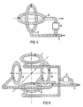
Mit der erfindungsgemäßen Ausgestaltung der Oberflächenspule sind jedoch auch Antennenanordnungen mit zirkular polarisierten HF-Feldern möglich, die bei geringerer Sendeleistung noch homogenere HF-Anregung als lineare Felder erzeugen. Ein erstes Ausführungsbeispiel für eine Anordnung mit zirkular polarisiertem HF-Feld ist in Fig. 4 dargestellt. Dabei sind zwei Oberflächenspulen A, B räumlich senkrecht zueinander angeordnet, so daß sie einen Untersuchungsraum einschließen. Die Oberflächenspule A wird an die Einspeiseleitung 1 über einen 90°-Phasenschieber 6 angeschlossen, so daß im Untersuchungsraum ein zirkular polarisiertes Feld entsteht und erfaßt werden kann.With the configuration of the surface coil according to the invention, however, antenna arrangements with circularly polarized RF fields are also possible, which generate even more homogeneous RF excitation than linear fields with a lower transmission power. A first exemplary embodiment of an arrangement with a circularly polarized RF field is shown in FIG. 4. Two surface coils A, B are arranged spatially perpendicular to one another so that they enclose an examination room. The surface coil A is connected to the feed line 1 via a 90 °
Ein weiteres Ausführungsbeispiel für zirkular polarisierte HF-Felder, das in einem größeren Volumenbereich eine homogene HF-Anregung ermöglicht, ist in Fig. 5 dargestellt. Dabei sind zwei Spulenpaare A, C und B, D vorgesehen, deren Achsen senkrecht zueinander stehen. Die beiden Spulen A, C und B, D jedes Spulenpaares sind räumlich parallel zueinander angeordnet und elektrisch parallel geschaltet. Während das Spulenpaar B, D direkt an die Einspeiseleitung 1 angeschlossen ist, erfolgt die Einspeisung des Spulenpaares A, C über die Ein speiseleitung 1 und einen 90°-Phasenschieber 6. Die Oberflächenspulen A - D schließen einen Untersuchungsraum ein, der mit einem zirkular polarisierten HF-Feld beaufschlagbar und erfaßbar ist.A further exemplary embodiment for circularly polarized RF fields, which enables homogeneous RF excitation in a larger volume range, is shown in FIG. 5. Two pairs of coils A, C and B, D are provided, the axes of which are perpendicular to one another. The two coils A, C and B, D of each pair of coils are arranged spatially parallel to one another and electrically connected in parallel. While the coil pair B, D is connected directly to the feed line 1, the coil pair A, C is fed via the input Feed line 1 and a 90 °
Claims (9)
Applications Claiming Priority (2)
| Application Number | Priority Date | Filing Date | Title |
|---|---|---|---|
| DE3540872 | 1985-11-18 | ||
| DE3540872 | 1985-11-18 |
Related Child Applications (1)
| Application Number | Title | Priority Date | Filing Date |
|---|---|---|---|
| EP89117595.2 Division-Into | 1986-08-11 |
Publications (2)
| Publication Number | Publication Date |
|---|---|
| EP0222982A1 true EP0222982A1 (en) | 1987-05-27 |
| EP0222982B1 EP0222982B1 (en) | 1990-10-31 |
Family
ID=6286298
Family Applications (2)
| Application Number | Title | Priority Date | Filing Date |
|---|---|---|---|
| EP86111082A Expired - Lifetime EP0222982B1 (en) | 1985-11-18 | 1986-08-11 | Surface coil for nuclear magnetic resonance analysis |
| EP89117595A Expired - Lifetime EP0352824B1 (en) | 1985-11-18 | 1986-08-11 | Local coil arrangement for NMR examination |
Family Applications After (1)
| Application Number | Title | Priority Date | Filing Date |
|---|---|---|---|
| EP89117595A Expired - Lifetime EP0352824B1 (en) | 1985-11-18 | 1986-08-11 | Local coil arrangement for NMR examination |
Country Status (4)
| Country | Link |
|---|---|
| US (1) | US4816766A (en) |
| EP (2) | EP0222982B1 (en) |
| JP (1) | JPH0782942B2 (en) |
| DE (2) | DE3689266D1 (en) |
Cited By (8)
| Publication number | Priority date | Publication date | Assignee | Title |
|---|---|---|---|---|
| FR2615041A1 (en) * | 1987-05-07 | 1988-11-10 | Thomson Cgr | ELECTROMAGNETIC ANTENNA AND DRIVE ANTENNA FOR A NUCLEAR MAGNETIC RESONANCE APPARATUS PROVIDED WITH SUCH AN ELECTROMAGNETIC ANTENNA |
| WO1988009926A1 (en) * | 1987-06-02 | 1988-12-15 | Thomson-Cgr | Receiving aerial for nmr imaging apparatus |
| EP0303879A1 (en) * | 1987-08-13 | 1989-02-22 | Siemens Aktiengesellschaft | Local coil for the NMR examination of an object |
| EP0304249A2 (en) * | 1987-08-17 | 1989-02-22 | Picker International, Inc. | Magnetic resonance methods and apparatus |
| GB2219861A (en) * | 1988-06-15 | 1989-12-20 | Nat Res Dev | Surface coil structures for nmr imaging and spectroscopy |
| EP0361190A1 (en) * | 1988-09-23 | 1990-04-04 | Siemens Aktiengesellschaft | Surface coil arrangement for examinations with the aid of nuclear magnetic resonance |
| WO1995022768A1 (en) * | 1994-02-17 | 1995-08-24 | Rubinson Kenneth A | Truncated nuclear magnetic imaging probe |
| DE4343932A1 (en) * | 1993-12-22 | 1995-08-31 | Siemens Ag | Local antenna for magnetic resonance device |
Families Citing this family (29)
| Publication number | Priority date | Publication date | Assignee | Title |
|---|---|---|---|---|
| JPS6417636A (en) * | 1987-07-14 | 1989-01-20 | Hitachi Medical Corp | Nuclear magnetic resonance imaging apparatus |
| US4799016A (en) * | 1987-07-31 | 1989-01-17 | General Electric Company | Dual frequency NMR surface coil |
| JPS6446634A (en) * | 1987-08-14 | 1989-02-21 | Jeol Ltd | Coupling oil of loop gap resonator |
| DE3918743A1 (en) * | 1989-06-08 | 1990-12-13 | Philips Patentverwaltung | HIGH FREQUENCY SQUARE COIL ARRANGEMENT |
| US5131392A (en) * | 1990-02-13 | 1992-07-21 | Brigham & Women's Hospital | Use of magnetic field of magnetic resonance imaging devices as the source of the magnetic field of electromagnetic transducers |
| US5196796A (en) * | 1991-08-06 | 1993-03-23 | Medrad, Inc. | Anatomically conformal quadrature mri surface coil |
| US5680044A (en) * | 1992-11-18 | 1997-10-21 | Oxford Instruments Plc | Oscillating magnetic field generating assembly |
| DE4343931C2 (en) * | 1993-12-22 | 1997-09-04 | Siemens Ag | Local antenna for a magnetic resonance device |
| US6054856A (en) * | 1998-04-01 | 2000-04-25 | The United States Of America As Represented By The Secretary Of The Navy | Magnetic resonance detection coil that is immune to environmental noise |
| AU2002301342B9 (en) * | 1998-04-01 | 2006-11-02 | The Government Of The United States Of America, As Represented By The Secretary Of The Navy | Magnetic Resonance |
| US6636040B1 (en) | 1999-12-17 | 2003-10-21 | Fonar Corporation | MRI antenna |
| US6847210B1 (en) | 1999-12-17 | 2005-01-25 | Fonar Corporation | MRI antenna |
| US6727698B1 (en) | 1999-12-17 | 2004-04-27 | Fonar Corporation | MRI antennas including electrically connected inner and outer conductors, and MRI systems including such antennas |
| US6504369B1 (en) * | 2000-09-05 | 2003-01-07 | Koninklijke Philips Electronics, N.V. | Decoupling two or more channels on RF coil systems |
| WO2003076952A2 (en) | 2001-07-02 | 2003-09-18 | The United States Of America, As Represented By The Secretary Of The Navy | Three-frequency nuclear quadrupole resonance (nqr) |
| US6980000B2 (en) * | 2003-04-29 | 2005-12-27 | Varian, Inc. | Coils for high frequency MRI |
| JP4787033B2 (en) * | 2006-02-15 | 2011-10-05 | 株式会社日立製作所 | Nuclear magnetic resonance signal solenoid coil and nuclear magnetic resonance signal acquisition apparatus |
| JP2010008282A (en) * | 2008-06-27 | 2010-01-14 | Toshiba Corp | Magnetic field probe, current distribution measuring device, and radio device |
| JP2010154175A (en) * | 2008-12-25 | 2010-07-08 | Futaba Corp | Mobile body remote control system |
| JP2010239274A (en) * | 2009-03-30 | 2010-10-21 | Brother Ind Ltd | One-wavelength loop antenna |
| JP2011222761A (en) * | 2010-04-09 | 2011-11-04 | National Institute Of Information & Communication Technology | Helmholtz coil type magnetic field generator using shielded loop |
| US20150318612A1 (en) * | 2012-11-19 | 2015-11-05 | Lars Karlsson | Method and Apparatus for Wideband, Polarimetric Reception of High Frequency Radio Signals |
| US9678180B2 (en) * | 2014-05-06 | 2017-06-13 | Quality Electrodynamics, Llc | Coaxial cable magnetic resonance image (MRI) coil |
| US9933501B2 (en) | 2014-08-04 | 2018-04-03 | Quality Electrodynamics, Llc | Magnetic resonance imaging (MRI) coil with integrated decoupling |
| JP6381467B2 (en) * | 2015-03-20 | 2018-08-29 | 株式会社Pfu | Coaxial metal body manufacturing method |
| DE102016113839A1 (en) * | 2016-07-27 | 2018-02-01 | Stephan Eder | coil assembly |
| US10739422B2 (en) | 2017-05-16 | 2020-08-11 | Quality Electrodynamics, Llc | Flexible coaxial magnetic resonance imaging (MRI) coil with integrated decoupling |
| DE102018201476A1 (en) * | 2018-01-31 | 2019-08-01 | Siemens Healthcare Gmbh | Local coil for magnetic resonance tomograph |
| GB2604131A (en) * | 2021-02-25 | 2022-08-31 | Tesla Dynamic Coils BV | MRI systems and RF transmit antenna arrangements |
Citations (8)
| Publication number | Priority date | Publication date | Assignee | Title |
|---|---|---|---|---|
| US2615134A (en) * | 1946-01-09 | 1952-10-21 | Rca Corp | Antenna |
| DE912583C (en) * | 1943-02-20 | 1954-05-31 | Hans Wittbrodt Dipl Ing | High antenna effect free loop antenna |
| EP0047065A2 (en) * | 1980-08-29 | 1982-03-10 | Technicare Corporation | Distributed phase RF coil |
| DE3140319A1 (en) * | 1981-10-10 | 1983-04-21 | Klaus 3300 Braunschweig Münter | Electrically screened broadband antenna for the in-phase detection of the magnetic components of an alternating electromagnetic field |
| WO1984000214A1 (en) * | 1982-06-28 | 1984-01-19 | Oxford Res Syst | Radiofrequency transducer and method of using same |
| FR2530816A1 (en) * | 1982-07-21 | 1984-01-27 | Inst Physique Biolog | Radio-frequency antenna system for examining voluminous bodies by nuclear magnetic resonance and imaging apparatus using such a system. |
| EP0160942A2 (en) * | 1984-05-10 | 1985-11-13 | General Electric Company | Elliptical cross-section slotted-tube radio-frequency resonator for nuclear magnetic resonance imaging |
| EP0170558A1 (en) * | 1984-07-10 | 1986-02-05 | General Electric Cgr S.A. | Device for creating and/or receiving alternating magnetic fields used in a nuclear magnetic-resonance apparatus |
Family Cites Families (13)
| Publication number | Priority date | Publication date | Assignee | Title |
|---|---|---|---|---|
| GB419783A (en) * | 1933-02-02 | 1934-11-19 | Marconi Wireless Telegraph Co | Improvements in and relating to wireless receiving apparatus |
| US2690509A (en) * | 1951-02-05 | 1954-09-28 | Toth Emerick | Omnidirectional loop antenna system |
| GB744116A (en) * | 1953-12-04 | 1956-02-01 | Francis Richard Pettit | Improvements in wireless aerials and feeders |
| JPS5226879B2 (en) * | 1972-09-19 | 1977-07-16 | ||
| US4083006A (en) * | 1973-07-10 | 1978-04-04 | Agency Of Industrial Science & Technology | Loop type standard magnetic field generator |
| US4595928A (en) * | 1978-12-28 | 1986-06-17 | Wingard Jefferson C | Bi-directional antenna array |
| US4373163A (en) * | 1980-07-14 | 1983-02-08 | I.D. Engineering, Inc. | Loop antenna for security systems |
| US4452250A (en) * | 1982-04-29 | 1984-06-05 | Britton Chance | NMR System for the non-invasive study of phosphorus metabilism |
| FR2534692A1 (en) * | 1982-10-15 | 1984-04-20 | Thomson Csf | HIGH-SENSITIVITY, BROADBAND ALTERNATE MAGNETIC FIELD SENSOR DEVICE AND MEASURING APPARATUS USING THE SAME |
| GB8431457D0 (en) * | 1984-12-13 | 1985-01-23 | Maxview Aerials Ltd | Aerials |
| US4691163A (en) * | 1985-03-19 | 1987-09-01 | Elscint Ltd. | Dual frequency surface probes |
| DE3515190A1 (en) * | 1985-04-26 | 1986-11-06 | Siemens AG, 1000 Berlin und 8000 München | CORE SPIN TOMOGRAPHY UNIT |
| US4752738A (en) * | 1985-08-14 | 1988-06-21 | Picker International, Inc. | Three dimensional localized coil for magnetic resonance imaging |
-
1986
- 1986-08-11 DE DE89117595T patent/DE3689266D1/en not_active Expired - Fee Related
- 1986-08-11 EP EP86111082A patent/EP0222982B1/en not_active Expired - Lifetime
- 1986-08-11 DE DE8686111082T patent/DE3675339D1/en not_active Expired - Fee Related
- 1986-08-11 EP EP89117595A patent/EP0352824B1/en not_active Expired - Lifetime
- 1986-11-17 JP JP61273839A patent/JPH0782942B2/en not_active Expired - Lifetime
-
1988
- 1988-08-17 US US07/233,905 patent/US4816766A/en not_active Expired - Fee Related
Patent Citations (8)
| Publication number | Priority date | Publication date | Assignee | Title |
|---|---|---|---|---|
| DE912583C (en) * | 1943-02-20 | 1954-05-31 | Hans Wittbrodt Dipl Ing | High antenna effect free loop antenna |
| US2615134A (en) * | 1946-01-09 | 1952-10-21 | Rca Corp | Antenna |
| EP0047065A2 (en) * | 1980-08-29 | 1982-03-10 | Technicare Corporation | Distributed phase RF coil |
| DE3140319A1 (en) * | 1981-10-10 | 1983-04-21 | Klaus 3300 Braunschweig Münter | Electrically screened broadband antenna for the in-phase detection of the magnetic components of an alternating electromagnetic field |
| WO1984000214A1 (en) * | 1982-06-28 | 1984-01-19 | Oxford Res Syst | Radiofrequency transducer and method of using same |
| FR2530816A1 (en) * | 1982-07-21 | 1984-01-27 | Inst Physique Biolog | Radio-frequency antenna system for examining voluminous bodies by nuclear magnetic resonance and imaging apparatus using such a system. |
| EP0160942A2 (en) * | 1984-05-10 | 1985-11-13 | General Electric Company | Elliptical cross-section slotted-tube radio-frequency resonator for nuclear magnetic resonance imaging |
| EP0170558A1 (en) * | 1984-07-10 | 1986-02-05 | General Electric Cgr S.A. | Device for creating and/or receiving alternating magnetic fields used in a nuclear magnetic-resonance apparatus |
Non-Patent Citations (1)
| Title |
|---|
| PATENTS ABSTRACTS OF JAPAN, Band 5, Nr. 78 (E-58)[750], 22. Mai 1981; & JP-A-56 27 509 (PIONEER K.K.) 17-03-1981 * |
Cited By (15)
| Publication number | Priority date | Publication date | Assignee | Title |
|---|---|---|---|---|
| WO1988008971A1 (en) * | 1987-05-07 | 1988-11-17 | General Electric Cgr S.A. | Electromagnetic antenna and excitation antenna provided with such electromagnetic antenna for a nuclear magnetic resonance apparatus |
| FR2615041A1 (en) * | 1987-05-07 | 1988-11-10 | Thomson Cgr | ELECTROMAGNETIC ANTENNA AND DRIVE ANTENNA FOR A NUCLEAR MAGNETIC RESONANCE APPARATUS PROVIDED WITH SUCH AN ELECTROMAGNETIC ANTENNA |
| US5363113A (en) * | 1987-05-07 | 1994-11-08 | General Electric Cgr S.A. | Electromagnetic antenna and excitation antenna provided with such electromagnetic antenna for a nuclear magnetic resonance apparatus |
| WO1988009926A1 (en) * | 1987-06-02 | 1988-12-15 | Thomson-Cgr | Receiving aerial for nmr imaging apparatus |
| EP0303879A1 (en) * | 1987-08-13 | 1989-02-22 | Siemens Aktiengesellschaft | Local coil for the NMR examination of an object |
| US4835472A (en) * | 1987-08-13 | 1989-05-30 | Siemens Aktiengesellschaft | Local coil for detecting nuclear magnetic resonance signals from an examination subject |
| EP0304249A3 (en) * | 1987-08-17 | 1990-09-12 | Picker International, Inc. | Magnetic resonance methods and apparatus |
| EP0304249A2 (en) * | 1987-08-17 | 1989-02-22 | Picker International, Inc. | Magnetic resonance methods and apparatus |
| GB2219861A (en) * | 1988-06-15 | 1989-12-20 | Nat Res Dev | Surface coil structures for nmr imaging and spectroscopy |
| US5143688A (en) * | 1988-06-15 | 1992-09-01 | National Research Development Corporation | Surface electrical coil structures |
| GB2219861B (en) * | 1988-06-15 | 1993-05-12 | Nat Res Dev | Improvements in or relating to surface electrical coil structures |
| US5006805A (en) * | 1988-09-23 | 1991-04-09 | Siemens Aktiengesellschaft | Surface coil arrangement for use in a nuclear magnetic resonance apparatus |
| EP0361190A1 (en) * | 1988-09-23 | 1990-04-04 | Siemens Aktiengesellschaft | Surface coil arrangement for examinations with the aid of nuclear magnetic resonance |
| DE4343932A1 (en) * | 1993-12-22 | 1995-08-31 | Siemens Ag | Local antenna for magnetic resonance device |
| WO1995022768A1 (en) * | 1994-02-17 | 1995-08-24 | Rubinson Kenneth A | Truncated nuclear magnetic imaging probe |
Also Published As
| Publication number | Publication date |
|---|---|
| EP0222982B1 (en) | 1990-10-31 |
| JPH0782942B2 (en) | 1995-09-06 |
| DE3689266D1 (en) | 1993-12-09 |
| EP0352824B1 (en) | 1993-11-03 |
| DE3675339D1 (en) | 1990-12-06 |
| JPS62128105A (en) | 1987-06-10 |
| EP0352824A1 (en) | 1990-01-31 |
| US4816766A (en) | 1989-03-28 |
Similar Documents
| Publication | Publication Date | Title |
|---|---|---|
| EP0222982B1 (en) | Surface coil for nuclear magnetic resonance analysis | |
| DE69834106T2 (en) | ARRANGEMENT OF A COPLANAR HTS RF SAMPLE COIL FOR NMR ATTRACTION ON MULTIPLE FREQUENCIES | |
| EP0073375B1 (en) | High-frequency device in a nuclear spin resonance apparatus | |
| DE60026795T2 (en) | Device magnetic resonance | |
| DE3427666C2 (en) | ||
| EP0200078B1 (en) | Apparatus for nuclear tomography | |
| DE3538952A1 (en) | HIGH-FREQUENCY COIL ARRANGEMENT FOR NUCLEAR SPIN RESON | |
| DE3500456A1 (en) | COIL ARRANGEMENT FOR AN NMR EXAMINER | |
| EP0361190A1 (en) | Surface coil arrangement for examinations with the aid of nuclear magnetic resonance | |
| DE4434948A1 (en) | Mammography antenna arrangement for MR investigation | |
| EP1267174A2 (en) | High-frequency coil assembly for a nuclear magnetic resonance imaging device, and NMR imaging device | |
| EP0303879B1 (en) | Local coil for the nmr examination of an object | |
| EP1275972A2 (en) | High frequency coil arrangement for an MR-apparatus | |
| DE4108997C2 (en) | RF coil arrangement for an NMR examination device | |
| EP0142077A1 (en) | High-frequency device in a nuclear-spin resonance apparatus with a surface coil | |
| EP0389868B1 (en) | Nuclear spin tomograph | |
| DE4138690C2 (en) | Circularly polarizing local antenna for a nuclear magnetic resonance device | |
| EP0432241B1 (en) | Probe head for whole-body nuclear-resonance tomography or local in vivo nuclear-resonance spectroscopy | |
| EP3194995B1 (en) | Measuring apparatus for weak electromagnetic signals from a sample at low frequencies, in addition to a method | |
| DE3628035A1 (en) | Surface coil arrangement for investigating NMR - uses two surface coils with inserted capacitances giving two resonance points | |
| DE102014105800B4 (en) | Device and method for the electrical connection of electronic assemblies by means of symmetrical shielded cables | |
| DE102012213995B3 (en) | System for electromagnetic excitation in a magnetic resonance tomography and magnetic resonance tomograph | |
| DE102015206788B3 (en) | NMR transmission / reception coil arrangement | |
| DE10109489B4 (en) | Spin resonance instrument with a static magnetic field | |
| DE4314338C2 (en) | High-frequency system of a magnetic resonance imaging system with shielding means for an E-field limitation |
Legal Events
| Date | Code | Title | Description |
|---|---|---|---|
| PUAI | Public reference made under article 153(3) epc to a published international application that has entered the european phase |
Free format text: ORIGINAL CODE: 0009012 |
|
| AK | Designated contracting states |
Kind code of ref document: A1 Designated state(s): DE FR GB NL |
|
| 17P | Request for examination filed |
Effective date: 19870708 |
|
| 17Q | First examination report despatched |
Effective date: 19890119 |
|
| GRAA | (expected) grant |
Free format text: ORIGINAL CODE: 0009210 |
|
| AK | Designated contracting states |
Kind code of ref document: B1 Designated state(s): DE FR GB NL |
|
| PG25 | Lapsed in a contracting state [announced via postgrant information from national office to epo] |
Ref country code: NL Effective date: 19901031 Ref country code: FR Effective date: 19901031 |
|
| XX | Miscellaneous (additional remarks) |
Free format text: TEILANMELDUNG 89117595.2 EINGEREICHT AM 11/08/86. |
|
| GBT | Gb: translation of ep patent filed (gb section 77(6)(a)/1977) | ||
| REF | Corresponds to: |
Ref document number: 3675339 Country of ref document: DE Date of ref document: 19901206 |
|
| NLV1 | Nl: lapsed or annulled due to failure to fulfill the requirements of art. 29p and 29m of the patents act | ||
| EN | Fr: translation not filed | ||
| PLBE | No opposition filed within time limit |
Free format text: ORIGINAL CODE: 0009261 |
|
| STAA | Information on the status of an ep patent application or granted ep patent |
Free format text: STATUS: NO OPPOSITION FILED WITHIN TIME LIMIT |
|
| 26N | No opposition filed | ||
| PGFP | Annual fee paid to national office [announced via postgrant information from national office to epo] |
Ref country code: GB Payment date: 19930714 Year of fee payment: 8 |
|
| PG25 | Lapsed in a contracting state [announced via postgrant information from national office to epo] |
Ref country code: GB Effective date: 19940811 |
|
| GBPC | Gb: european patent ceased through non-payment of renewal fee |
Effective date: 19940811 |
|
| PGFP | Annual fee paid to national office [announced via postgrant information from national office to epo] |
Ref country code: DE Payment date: 19951019 Year of fee payment: 10 |
|
| PG25 | Lapsed in a contracting state [announced via postgrant information from national office to epo] |
Ref country code: DE Effective date: 19970501 |