EP0222294A2 - Dynamically focused linear phased array acoustic imaging system - Google Patents
Dynamically focused linear phased array acoustic imaging system Download PDFInfo
- Publication number
- EP0222294A2 EP0222294A2 EP86115228A EP86115228A EP0222294A2 EP 0222294 A2 EP0222294 A2 EP 0222294A2 EP 86115228 A EP86115228 A EP 86115228A EP 86115228 A EP86115228 A EP 86115228A EP 0222294 A2 EP0222294 A2 EP 0222294A2
- Authority
- EP
- European Patent Office
- Prior art keywords
- transducer
- delay
- signals
- multiplexer
- output
- Prior art date
- Legal status (The legal status is an assumption and is not a legal conclusion. Google has not performed a legal analysis and makes no representation as to the accuracy of the status listed.)
- Granted
Links
Images


Classifications
-
- G—PHYSICS
- G10—MUSICAL INSTRUMENTS; ACOUSTICS
- G10K—SOUND-PRODUCING DEVICES; METHODS OR DEVICES FOR PROTECTING AGAINST, OR FOR DAMPING, NOISE OR OTHER ACOUSTIC WAVES IN GENERAL; ACOUSTICS NOT OTHERWISE PROVIDED FOR
- G10K11/00—Methods or devices for transmitting, conducting or directing sound in general; Methods or devices for protecting against, or for damping, noise or other acoustic waves in general
- G10K11/18—Methods or devices for transmitting, conducting or directing sound
- G10K11/26—Sound-focusing or directing, e.g. scanning
- G10K11/34—Sound-focusing or directing, e.g. scanning using electrical steering of transducer arrays, e.g. beam steering
- G10K11/341—Circuits therefor
- G10K11/345—Circuits therefor using energy switching from one active element to another
-
- G—PHYSICS
- G01—MEASURING; TESTING
- G01S—RADIO DIRECTION-FINDING; RADIO NAVIGATION; DETERMINING DISTANCE OR VELOCITY BY USE OF RADIO WAVES; LOCATING OR PRESENCE-DETECTING BY USE OF THE REFLECTION OR RERADIATION OF RADIO WAVES; ANALOGOUS ARRANGEMENTS USING OTHER WAVES
- G01S15/00—Systems using the reflection or reradiation of acoustic waves, e.g. sonar systems
- G01S15/88—Sonar systems specially adapted for specific applications
- G01S15/89—Sonar systems specially adapted for specific applications for mapping or imaging
- G01S15/8906—Short-range imaging systems; Acoustic microscope systems using pulse-echo techniques
- G01S15/8909—Short-range imaging systems; Acoustic microscope systems using pulse-echo techniques using a static transducer configuration
- G01S15/8915—Short-range imaging systems; Acoustic microscope systems using pulse-echo techniques using a static transducer configuration using a transducer array
- G01S15/8918—Short-range imaging systems; Acoustic microscope systems using pulse-echo techniques using a static transducer configuration using a transducer array the array being linear
Definitions
- This invention relates generally to an acoustic imaging system and is an improvement upon the system disclosed in U.S. patent 4,140,022 issued February 20, 1979 and entitled ACOUSTIC IMAGING APPARATUS that enables the system there disclosed to operate in the linear scanning mode with the inclusion of a simple programmable analog multiplexer.
- a sector phased array acoustic imaging system using phase changing means, heterodyning, tap selectors and a summing delay line is described in U.S. patent 4,140,022 issued February 20, 1979 to Samuel H. Maslak entitled ACOUSTIC IMAGING APPARATUS.
- the phase changing means of that patented imaging system, including heterodyning means connects between pairs of adjacent transducer elements and selected taps on a master summing delay line.
- the delay line taps are just close enough together to provide reasonable overlap of the pulse envelopes of the electrical signals received from individual transducer elements.
- Dynamic focusing is attained by adjusting the phases of the signals throughout reception using heterodyning means so that the cycles of carrier signal within the overlapped pulses have reasonable phase coherence, as is described in the patent.
- the present invention comprises in acoustic imaging apparatus having means for repeatedly transmitting pulses of acoustic pressure waves into a body to be examined, an array of transducers for transducing acoustic pulse echos that impinge on each of them into corresponding electrical signals, the improvement for scanning the array in linear imaging mode comprising a plurality of substantially identical transducer output processing channels; and control demultiplexer means ordering the control signals applied to each channel in a sequence that precisely compensates for the ordering of the transducer outputs connected to that channel.
- This invention improves upon the imaging system of patent 4,140,022 to enable operation of that system in the linear scanning mode by replacement of the M x M analog multiplexer with digital control circuitry which avoids switching the analog signal path.
- This circuitry may also be duplicated to operate on the transmit control signals. Collectively, this digital control circuitry is called "control demultiplexing.”
- the present invention modifies the system described in patent 4,140,022 thereby enabling efficient operation in the linear scanning mode.
- the present invention also provides a simple and generally applicable demultiplexing system by ordering of the control signals applied to identical channels that process the transducer transmit input signals or received outputs in a manner precisely corresponding to the scrambling that occurs by multiplexing groups of adjacent transducers operating in the linear scanning mode.
- the present invention also results in a reduction in costs and improved performance when compared to use of a signal demultiplexer for switching low-level analog signals.
- Fig. 1 illustrates the functional components for a linear scanning mode, including a transducer assembly 1 comprising a linear array 2 of N individual transducers 3, as shown in Fig. 2, and a digitally controlled analog multiplexer 4, for example, as described in U.S. patent 4,224,829.
- the multiplexer 4 selects a group of M adjacent transducers 3 from a substantially larger number N for connection to an M-wire transducer cable 5.
- the transducer cable 5 thus connects the transducer assembly 1 to signal processing components 6 in the imaging system.
- These signal processing components 6 may comprise a signal demultiplexer 7, which unscrambles the M multiplexer transducer signals, and an M-channel dynamic focusing component 8, such as is described in U.S. patent 4,140,022.
- Means to achieve appropriate demultiplexing of the multiplexed signals from the transducer assembly 1 are essential for proper phase alignment as is performed in the focusing component 8.
- this means consists of an array of M x M analog switches which are under digital control.
- Each analog switch when enabled, operates on the resultant signal of a single transducer signal prior to any coherent summation with signals from other transducers. Therefore the full dynamic range and bandwidth of each relatively low-level signal must be preserved in the analog switch.
- M is typically 32, 64 or 128 or so for a high performance imaging system, several thousand of these switches are typically required.
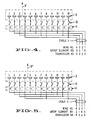
- Fig. 3 illustrates operation of the multiplexer in the simple case of an array 2 consisting of twelve transducers 3 connected in groups of four to a four-wire transducer cable 5 by the multiplexer 4.
- the multiplexer 4 is essentially a set of programmed switches 10 that close to connect a particular transducer 3 to one of the wires numbered 1 through 4 in the transducer cable 5.
- a first group of four transducers 1 through 4 connects by multiplexer switches 10 to the set of wires in the order shown, i.e., transducer 1 connects to wire 1, transducer 2 connects to wire 2 and so forth.
- the multiplexer selects, for example, the second group of four transducers in Fig. 4 comprising transducers 2, 3, 4 and 5.
- transducers 2, 3 and 4 remain connected to the same numbered wire in the transducer cable but multiplexer switch 10 to transducer 1 opens to disconnect transducer 1 from wire 1 and te switch to transducer 5 closes to connect transducer 5 to wire 1.
- the multiplexer connects the next group of four transducers 3, 4, 5 and 6 to the transducer cable wires.
- Transducers 3, 4 and 5 remain connected as before.
- multiplexer switch 10 to transducer 2 opens and that to transducer 6 closes whereby transducer 6 becomes connected to wire 2 and transducer 2 is disconnected.
- the transducer multiplexer 4 connects the signals from each transducer 3 to a particular wire in cable 5 with a cyclic ordering, grouping four adjacent transducer elements from the first to the last transducer element in the array.
- the multiplexer transistors or other switches 10 respond to the output of a shift register 11 by shifting "one” into the shift register locations corresponding to the desired group of M elements and shifting "zeros" into all other shift register locations. Each "one” turns the multiplexer switch 10 "on” and each "zero” turns the multiplexer switch "off".
- multiplexers could also be used, which might be complex N x M arrays of switches that would not cause the ordering to be cyclic.
- the invention described herein applies to simple multiplexers of any type wherein the reordering is a substantially cyclic, predetermined scrambling of the transducer signals, which are then unscrambled by control demultiplexing to avoid use of a complex M x M analog multiplexer.
- the prior art M x M analog demultiplexer 7 described above can be replaced by digital control signals which operate on the analog signals in systems such as the one described in U.S. paten 4,140,022.
- a digitally controlled multiplexer 15 routes the clock signals C1 through C M to the mixers 28 in order to achieve phase coherence between signals from pairs of adjacent transducers.
- the oscillator 30 produces a set of p unique signals, each of which has the same frequency but may have different phase relationships with one another.
- one of the p clock signals is selected by the multiplexer 15 and is routed to the mixer.
- the same clock signal may be routed to more than one mixer at the same time.
- control signals are derived from digital information read from ROM and RAM digital memory 16. Values are accessed sequentially by address counter 17 which permits formation of the clock signals that are then applied to mixer 281 through 28 M .
- the clock signals can be the phased outputs of a digital oscillator 30 as described in U.S. patent 4,140,022. If the address counter 17 is appropriately initialized for each acoustic scan line, taking into account the predetermined cyclic multiplexing of multiplexer 4, then demultiplexing occurs in a way which is functionally equivalent to actual switching of the M analog signals as would otherwise be done with an M x M analog demultiplexer. This digital control circuitry is collectively called "control demultiplexing".
- each signal processing channel includes variable gain amplifier 261 - 26 M that may have time gain compensation for attenuation of the ultrasonic energy as a function of distance in the scanned body.
- the demultiplexed outputs of the phase changing mixers 281 - 28 M are combined in adders 34 and then supplied to tap selectors 38 on a summing delay line.
- the output of the summing delay line is then subject to subsequent processing such as detection, amplification, etc., for ultimate display.
- Fig. 6 The technique illustrated in Fig. 6 is general and can be applied to many different types of systems.
- the principle involved is the provision of a plurality of substantially identical signal processing channels and the provision of control signals to each channel and that are ordered to precisely compensate for the predetermined ordering that occurs in the transducer multiplexer 4.
- Fig. 6 illustrates control demultiplexing applied to the system of U.S. patent 4,140,022 with the channels thereof being arranged in phased pairs
- this invention applies equally well in K-tuples where K might be 1, 2, 3, 4 or more.
- Each channel includes a preamplifier with protection circuit 24, a variable gain amplifier 26, followed by mixer 28, the outputs of which are combined in an adder 34.
- the intermediate frequency output of each adder 34 supplies a matrix switch or the tap selector 38 described in U.S. patent 4,140,022.
- the digitally controlled-multiplexer 15 selects and routes one of the plurality of individual clock signals from oscillator 30 for connection to mixers 28.
- the multiplexer 15 also supplies corresponding control signals to tap selectors 381-38 M/e for each phased pair to connect its output to the set of taps in master delay line 40 which cover the delay range with sufficiently fine quantization for each selected transducer group so as to provide signal overlap at the summing point S.
- Figs. 7A through 7D show the result of the control demultiplexing for several consecutive configurations.
- Fig. 7A shows connection between the first M transducers 3 to the corresponding M connections on the multiplexer 4.
- the signal received from each transducer is mixed and phase shifted with control signals C1-C M .
- the control signals C1-C M are not necessarily all different but are selected ones of the available phased outputs of the digital oscillator 30. There may be only p unique control signals corresponding to p phases of the oscillator where p ⁇ M.
- the resultant analog signals are combined as phased pairs at adders 341-34 M/e to produce phased intermediate frequency signals P1-P M/e . Each of these is now given the appropriate delay through tap selection means 38 controlled by signals D1-D M/e from memory 16 and address counter 17.
- Fig. 7B shows transducers 2 through M+1 connected via the multiplexer 4 to the appropriately numbered wires, as discussed previously.
- control signals C'1-C' M which might in general differ from signals C1-C M are read from ROM and RAM memory 16 to maintain coherence between appropriate pairs of elements.
- the signals generated from transducers 2 and M+1 are phase coherent when the scan lines are normal or nearly normal to the transducer face of a planar linear array of transducers. These signals are then combined at adder 341 to produce phased intermediate frequency signal P1 which is connected to summing delay line 40 of Fig. 6 by tap selector 381.
- Fig. 7C shows transducer M coupled to the preceding transducer and transducers M + 1 and M + 2 coupled in phased pairs by adders 34 M/e and 341, respectively.
- Fig. 7D shows transducer 4 coupled to transducer M + 3 at adder 34 e . The sequence continues until the entire array is scanned.
- the linear scanning mode is not limited to the case shown in Fig. 2 with scan lines 9-9' parallel and at right angles to a line connecting the face of each transducer, but parallel or nearly parallel scan lines may be at any predetermined angle to the array normal.
- Parallel scanning at a predetermined angle substantially different from the array normal may introduce excessive delay between the outer transducer elements for certain transducer groups (e.g. transducer elements 2 and M + 1 in Fig. 7B and transducer elements 4, and M + 3 in Fig. 7D).
- one of the outer transducer elements e.g. transducer element M + 1 in Fig. 7B and element M + 3 in Fig. 7D
- transducer signals generated from transducers 1 and M are essentially adjacent in that these signals are not separated by substantial time delay.
- the same set of control signals namely C1-C M are used in the configurations shown in Figs. 7A and 7C.
- the same set of control signals namely C'1-C' M are used in the configurations of Figs. 7B and 7D. It is the function of the address counter 17 to determine when each predetermined set of control signals is required.
- a similar set of control signals, such as D1-D M/e or D'1-D' M/e are also required to specify the tap selection for connection to the summing delay line 40.
- the above examples specified the sets of control signals in the case of phased pairs. In the case of phased triplets or K-tuplets, additional sets would be required.
- control demultiplexing has been shown for the receive channels, it may also be applied to transmit channels using a different set of control signals in a different control memory. Steering and focusing data supplied to the individual transmit channels for the transducers 3 is scrambled by another digitally controlled multiplexer in a fashion which will be unscrambled by the multiplexer 4 that has been previously described.
- TGC time gain compensation signals
- control demultiplexing means described may be applied to system architectures other than one requiring the described tap selectors.
- control demultiplexing can be used with the architecture described in copending U.S. application Serial No. 607,670 filed May 7, 1984 and entitled PHASED ARRAY ACOUSTIC IMAGING SYSTEM, now patent 4,550,607 issued November 5, 1985.
Abstract
Description
- This invention relates generally to an acoustic imaging system and is an improvement upon the system disclosed in U.S. patent 4,140,022 issued February 20, 1979 and entitled ACOUSTIC IMAGING APPARATUS that enables the system there disclosed to operate in the linear scanning mode with the inclusion of a simple programmable analog multiplexer.
- A sector phased array acoustic imaging system using phase changing means, heterodyning, tap selectors and a summing delay line is described in U.S. patent 4,140,022 issued February 20, 1979 to Samuel H. Maslak entitled ACOUSTIC IMAGING APPARATUS. The phase changing means of that patented imaging system, including heterodyning means, connects between pairs of adjacent transducer elements and selected taps on a master summing delay line. The delay line taps are just close enough together to provide reasonable overlap of the pulse envelopes of the electrical signals received from individual transducer elements. Dynamic focusing is attained by adjusting the phases of the signals throughout reception using heterodyning means so that the cycles of carrier signal within the overlapped pulses have reasonable phase coherence, as is described in the patent.
- However, that patented system cannot operate in a linear scanning mode, in which all acoustic scan lines are substantially parallel, without the addition of multiplexer means. That system could operate in the linear scanning mode in a known manner with the inclusion of a programmable analog multiplexer which is M x M in further conjunction with transducer switching means as described in U.S. patent 4,224,829. Construction of a M x M analog multiplexer is expensive, since M is typically 64 or so for a high performance system, and is complex hardware since full bandwidth and dynamic range of the low-level transducer outputs must be preserved.
- The present invention comprises in acoustic imaging apparatus having means for repeatedly transmitting pulses of acoustic pressure waves into a body to be examined, an array of transducers for transducing acoustic pulse echos that impinge on each of them into corresponding electrical signals, the improvement for scanning the array in linear imaging mode comprising a plurality of substantially identical transducer output processing channels; and control demultiplexer means ordering the control signals applied to each channel in a sequence that precisely compensates for the ordering of the transducer outputs connected to that channel.
- This invention improves upon the imaging system of patent 4,140,022 to enable operation of that system in the linear scanning mode by replacement of the M x M analog multiplexer with digital control circuitry which avoids switching the analog signal path. This circuitry may also be duplicated to operate on the transmit control signals. Collectively, this digital control circuitry is called "control demultiplexing."
- The present invention modifies the system described in patent 4,140,022 thereby enabling efficient operation in the linear scanning mode.
- The present invention also provides a simple and generally applicable demultiplexing system by ordering of the control signals applied to identical channels that process the transducer transmit input signals or received outputs in a manner precisely corresponding to the scrambling that occurs by multiplexing groups of adjacent transducers operating in the linear scanning mode.
- The present invention also results in a reduction in costs and improved performance when compared to use of a signal demultiplexer for switching low-level analog signals.
- Other advantages of this invention will become apparent upon consideration of the following description of a preferred embodiment and the accompanying drawings.
-
- Fig. 1 schematically illustrates a planar linear array imaging system using a signal multiplexer and demultiplexer;
- Fig. 2 illustrates in cross section a planar linear array of N transducers;
- Fig. 3 illustrates a 12 to 4 cyclic
multiplexer selecting group 1 for connection to a four-wire transducer cable; - Fig. 4 illustrates a 12 to 4 cyclic multiplexer shown selecting
group 2 for connection to the cable; - Fig. 5 illustrates a 12 to 4 cyclic multiplexer shown selecting
group 3 for connection to the cable; - Fig. 6 is a simplified block diagram of portions of the circuitry described in U.S. patent 4,140,022 modified for operation in the linear scanning mode; and
- Fig. 7A, 7B, 7C and 7D illustrate the functional manner and means for demultiplexing several consecutive configurations of multiplexed receive signals.
- Fig. 1 illustrates the functional components for a linear scanning mode, including a
transducer assembly 1 comprising alinear array 2 of Nindividual transducers 3, as shown in Fig. 2, and a digitally controlledanalog multiplexer 4, for example, as described in U.S. patent 4,224,829. Themultiplexer 4 selects a group of Madjacent transducers 3 from a substantially larger number N for connection to an M-wire transducer cable 5. Thetransducer cable 5 thus connects thetransducer assembly 1 tosignal processing components 6 in the imaging system. Thesesignal processing components 6 may comprise asignal demultiplexer 7, which unscrambles the M multiplexer transducer signals, and an M-channel dynamic focusingcomponent 8, such as is described in U.S. patent 4,140,022. - Means to achieve appropriate demultiplexing of the multiplexed signals from the
transducer assembly 1 are essential for proper phase alignment as is performed in the focusingcomponent 8. In the prior art, this means consists of an array of M x M analog switches which are under digital control. Each analog switch, when enabled, operates on the resultant signal of a single transducer signal prior to any coherent summation with signals from other transducers. Therefore the full dynamic range and bandwidth of each relatively low-level signal must be preserved in the analog switch. Also, since M is typically 32, 64 or 128 or so for a high performance imaging system, several thousand of these switches are typically required. - The multiplexing, as will be apparent from a consideration of Figs. 3, 4 and 5, scrambles the order of connection of a transducer output in a predetermined cyclic pattern to any particular one of the M wires in the
transducer cable 5. Fig. 3 illustrates operation of the multiplexer in the simple case of anarray 2 consisting of twelvetransducers 3 connected in groups of four to a four-wire transducer cable 5 by themultiplexer 4. Themultiplexer 4 is essentially a set of programmedswitches 10 that close to connect aparticular transducer 3 to one of the wires numbered 1 through 4 in thetransducer cable 5. In Fig. 3 a first group of fourtransducers 1 through 4 connects bymultiplexer switches 10 to the set of wires in the order shown, i.e.,transducer 1 connects towire 1,transducer 2 connects towire 2 and so forth. - The multiplexer then selects, for example, the second group of four transducers in Fig. 4 comprising
transducers instance transducers multiplexer switch 10 to transducer 1 opens to disconnecttransducer 1 fromwire 1 and te switch to transducer 5 closes to connecttransducer 5 towire 1. - Then, in Fig. 5, the multiplexer connects the next group of four
transducers Transducers multiplexer switch 10 to transducer 2 opens and that to transducer 6 closes wherebytransducer 6 becomes connected towire 2 andtransducer 2 is disconnected. - Thus, as has been described, for a linear scanning mode the
transducer multiplexer 4 connects the signals from eachtransducer 3 to a particular wire incable 5 with a cyclic ordering, grouping four adjacent transducer elements from the first to the last transducer element in the array. The multiplexer transistors orother switches 10 respond to the output of ashift register 11 by shifting "one" into the shift register locations corresponding to the desired group of M elements and shifting "zeros" into all other shift register locations. Each "one" turns themultiplexer switch 10 "on" and each "zero" turns the multiplexer switch "off". - Other types of multiplexers could also be used, which might be complex N x M arrays of switches that would not cause the ordering to be cyclic. The invention described herein applies to simple multiplexers of any type wherein the reordering is a substantially cyclic, predetermined scrambling of the transducer signals, which are then unscrambled by control demultiplexing to avoid use of a complex M x M analog multiplexer.
- The prior art M x M
analog demultiplexer 7 described above can be replaced by digital control signals which operate on the analog signals in systems such as the one described in U.S. paten 4,140,022. - As illustrated in Fig. 6 in block diagram form, a digitally controlled
multiplexer 15 routes the clock signals C₁ through CM to themixers 28 in order to achieve phase coherence between signals from pairs of adjacent transducers. Theoscillator 30 produces a set of p unique signals, each of which has the same frequency but may have different phase relationships with one another. For each of the M mixers, one of the p clock signals is selected by themultiplexer 15 and is routed to the mixer. The same clock signal may be routed to more than one mixer at the same time. There is no relationship between the number of unique clock signals, p, and the number of channels, M. These control signals may be applied in such a way that precisely accounts for the cyclic ordering of the signals which are received from thetransducer multiplexer 4. The control signals are derived from digital information read from ROM and RAMdigital memory 16. Values are accessed sequentially byaddress counter 17 which permits formation of the clock signals that are then applied to mixer 28₁ through 28M. The clock signals can be the phased outputs of adigital oscillator 30 as described in U.S. patent 4,140,022. If theaddress counter 17 is appropriately initialized for each acoustic scan line, taking into account the predetermined cyclic multiplexing ofmultiplexer 4, then demultiplexing occurs in a way which is functionally equivalent to actual switching of the M analog signals as would otherwise be done with an M x M analog demultiplexer. This digital control circuitry is collectively called "control demultiplexing". - In Fig. 6 each signal processing channel includes variable gain amplifier 26₁ - 26M that may have time gain compensation for attenuation of the ultrasonic energy as a function of distance in the scanned body. The demultiplexed outputs of the phase changing mixers 28₁ - 28M are combined in
adders 34 and then supplied to tapselectors 38 on a summing delay line. The output of the summing delay line is then subject to subsequent processing such as detection, amplification, etc., for ultimate display. - The technique illustrated in Fig. 6 is general and can be applied to many different types of systems. The principle involved is the provision of a plurality of substantially identical signal processing channels and the provision of control signals to each channel and that are ordered to precisely compensate for the predetermined ordering that occurs in the
transducer multiplexer 4. - Although Fig. 6 illustrates control demultiplexing applied to the system of U.S. patent 4,140,022 with the channels thereof being arranged in phased pairs, this invention applies equally well in K-tuples where K might be 1, 2, 3, 4 or more. Each channel includes a preamplifier with
protection circuit 24, avariable gain amplifier 26, followed bymixer 28, the outputs of which are combined in anadder 34. The intermediate frequency output of eachadder 34 supplies a matrix switch or thetap selector 38 described in U.S. patent 4,140,022. The digitally controlled-multiplexer 15 selects and routes one of the plurality of individual clock signals fromoscillator 30 for connection tomixers 28. Themultiplexer 15 also supplies corresponding control signals to tap selectors 38₁-38M/e for each phased pair to connect its output to the set of taps inmaster delay line 40 which cover the delay range with sufficiently fine quantization for each selected transducer group so as to provide signal overlap at the summing point S. - Placement of
tap selectors 38 after themixers 28 in the signal flow path combined with the here-described ordering of processing channel and tap selector controls allows the system shown in U.S. patent 4,140,022 to operate in the linear scanning mode as described herein as well as the sector phased array imaging mode described in that patent. - To see how control demultiplexing works in a functional sense, consider Figs. 7A through 7D, which show the result of the control demultiplexing for several consecutive configurations. Fig. 7A shows connection between the
first M transducers 3 to the corresponding M connections on themultiplexer 4. The signal received from each transducer is mixed and phase shifted with control signals C₁-CM. The control signals C₁-CM are not necessarily all different but are selected ones of the available phased outputs of thedigital oscillator 30. There may be only p unique control signals corresponding to p phases of the oscillator where p<M. The resultant analog signals are combined as phased pairs at adders 34₁-34M/e to produce phased intermediate frequency signals P₁-PM/e. Each of these is now given the appropriate delay through tap selection means 38 controlled by signals D₁-DM/e frommemory 16 andaddress counter 17. - Fig. 7B shows
transducers 2 through M+1 connected via themultiplexer 4 to the appropriately numbered wires, as discussed previously. In this case, control signals C'₁-C'M which might in general differ from signals C₁-CM are read from ROM andRAM memory 16 to maintain coherence between appropriate pairs of elements. In particular, the signals generated fromtransducers 2 and M+1 are phase coherent when the scan lines are normal or nearly normal to the transducer face of a planar linear array of transducers. These signals are then combined atadder 34₁ to produce phased intermediate frequency signal P₁ which is connected to summingdelay line 40 of Fig. 6 bytap selector 38₁. - Fig. 7C shows transducer M coupled to the preceding transducer and transducers M + 1 and M + 2 coupled in phased pairs by
adders transducer 4 coupled to transducer M + 3 atadder 34e. The sequence continues until the entire array is scanned. - The linear scanning mode is not limited to the case shown in Fig. 2 with scan lines 9-9' parallel and at right angles to a line connecting the face of each transducer, but parallel or nearly parallel scan lines may be at any predetermined angle to the array normal. Parallel scanning at a predetermined angle substantially different from the array normal may introduce excessive delay between the outer transducer elements for certain transducer groups (
e.g. transducer elements 2 and M + 1 in Fig. 7B andtransducer elements 4, and M + 3 in Fig. 7D). For these certain transducer groups, one of the outer transducer elements (e.g. transducer element M + 1 in Fig. 7B and element M + 3 in Fig. 7D) may be turned "off" using apodizing means or by opening the appropriate transducer multiplexer switch. - In the linear scanning mode of Fig. 7A with scan lines normal to the transducer face, transducer signals generated from
transducers 1 and M are essentially adjacent in that these signals are not separated by substantial time delay. Further, the same set of control signals, namely C₁-CM are used in the configurations shown in Figs. 7A and 7C. Similarly, the same set of control signals, namely C'₁-C'M are used in the configurations of Figs. 7B and 7D. It is the function of theaddress counter 17 to determine when each predetermined set of control signals is required. A similar set of control signals, such as D₁-DM/e or D'₁-D'M/e are also required to specify the tap selection for connection to the summingdelay line 40. The above examples specified the sets of control signals in the case of phased pairs. In the case of phased triplets or K-tuplets, additional sets would be required. - Although application of "control demultiplexing" has been shown for the receive channels, it may also be applied to transmit channels using a different set of control signals in a different control memory. Steering and focusing data supplied to the individual transmit channels for the
transducers 3 is scrambled by another digitally controlled multiplexer in a fashion which will be unscrambled by themultiplexer 4 that has been previously described. - Various modifications of the invention become apparent. For example, even fewer tap selectors are needed if the identical processing channels are arranged in phased triples or K-tuples. Similarly, various transducers of a group may be apodized "off" by providing distinct time gain compensation signals (TGC) to
variable gain amplifiers 26 or by operating the mixer clocks at frequencies which produce signals outside the passband of the channel. - Furthermore, the "control demultiplexing" means described may be applied to system architectures other than one requiring the described tap selectors. For example, "control demultiplexing" can be used with the architecture described in copending U.S. application Serial No. 607,670 filed May 7, 1984 and entitled PHASED ARRAY ACOUSTIC IMAGING SYSTEM, now patent 4,550,607 issued November 5, 1985.
- These and other variations are within the scope of the invention defined in the following claims.
Claims (12)
Priority Applications (1)
| Application Number | Priority Date | Filing Date | Title |
|---|---|---|---|
| AT86115228T ATE95615T1 (en) | 1985-11-05 | 1986-11-03 | ULTRASONIC IMAGING SYSTEM WITH A DYNAMIC FOCUSED PHASE CONTROLLED LINEAR TRANSDUCER ARRANGEMENT. |
Applications Claiming Priority (2)
| Application Number | Priority Date | Filing Date | Title |
|---|---|---|---|
| US06/795,199 US4699009A (en) | 1985-11-05 | 1985-11-05 | Dynamically focused linear phased array acoustic imaging system |
| US795199 | 1985-11-05 |
Publications (3)
| Publication Number | Publication Date |
|---|---|
| EP0222294A2 true EP0222294A2 (en) | 1987-05-20 |
| EP0222294A3 EP0222294A3 (en) | 1987-09-30 |
| EP0222294B1 EP0222294B1 (en) | 1993-10-06 |
Family
ID=25164972
Family Applications (1)
| Application Number | Title | Priority Date | Filing Date |
|---|---|---|---|
| EP86115228A Expired - Lifetime EP0222294B1 (en) | 1985-11-05 | 1986-11-03 | Dynamically focused linear phased array acoustic imaging system |
Country Status (6)
| Country | Link |
|---|---|
| US (1) | US4699009A (en) |
| EP (1) | EP0222294B1 (en) |
| JP (1) | JP2592812B2 (en) |
| AT (1) | ATE95615T1 (en) |
| DE (1) | DE3689143T2 (en) |
| ES (1) | ES2046973T3 (en) |
Cited By (1)
| Publication number | Priority date | Publication date | Assignee | Title |
|---|---|---|---|---|
| EP0493036A1 (en) * | 1990-12-20 | 1992-07-01 | Fujitsu Limited | Acoustic imaging system |
Families Citing this family (49)
| Publication number | Priority date | Publication date | Assignee | Title |
|---|---|---|---|---|
| US5027821A (en) * | 1988-06-17 | 1991-07-02 | Kabushiki Kaisha Toshiba | Ultrasonic imaging apparatus |
| US5319390A (en) * | 1990-09-28 | 1994-06-07 | Fujitsu Limited | Thermal printer apparatus |
| US5213104A (en) * | 1991-10-24 | 1993-05-25 | Reynolds Charles A | Doppler ultrasound monitor system |
| US5713363A (en) * | 1991-11-08 | 1998-02-03 | Mayo Foundation For Medical Education And Research | Ultrasound catheter and method for imaging and hemodynamic monitoring |
| US5325860A (en) | 1991-11-08 | 1994-07-05 | Mayo Foundation For Medical Education And Research | Ultrasonic and interventional catheter and method |
| US5704361A (en) * | 1991-11-08 | 1998-01-06 | Mayo Foundation For Medical Education And Research | Volumetric image ultrasound transducer underfluid catheter system |
| US5488955A (en) * | 1992-07-22 | 1996-02-06 | Hewlett Packard Company | Magnetostriction transducer and an intraoperative probe for acoustic imaging |
| WO1995002197A1 (en) * | 1993-07-08 | 1995-01-19 | Siemens Aktiengesellschaft | Ultrasonic imaging system with a reduced number of lines between the main apparatus and a two-dimensional applicator |
| US5501222A (en) * | 1994-05-13 | 1996-03-26 | Briggs; Keith A. | System for imaging a region |
| US5675554A (en) * | 1994-08-05 | 1997-10-07 | Acuson Corporation | Method and apparatus for transmit beamformer |
| AU3361095A (en) | 1994-08-05 | 1996-03-04 | Acuson Corporation | Method and apparatus for transmit beamformer system |
| US5570691A (en) * | 1994-08-05 | 1996-11-05 | Acuson Corporation | Method and apparatus for real-time, concurrent adaptive focusing in an ultrasound beamformer imaging system |
| US5928152A (en) * | 1994-08-05 | 1999-07-27 | Acuson Corporation | Method and apparatus for a baseband processor of a receive beamformer system |
| US5793701A (en) * | 1995-04-07 | 1998-08-11 | Acuson Corporation | Method and apparatus for coherent image formation |
| US5549111A (en) * | 1994-08-05 | 1996-08-27 | Acuson Corporation | Method and apparatus for adjustable frequency scanning in ultrasound imaging |
| US6029116A (en) * | 1994-08-05 | 2000-02-22 | Acuson Corporation | Method and apparatus for a baseband processor of a receive beamformer system |
| US5685308A (en) * | 1994-08-05 | 1997-11-11 | Acuson Corporation | Method and apparatus for receive beamformer system |
| US5555534A (en) * | 1994-08-05 | 1996-09-10 | Acuson Corporation | Method and apparatus for doppler receive beamformer system |
| US5581517A (en) * | 1994-08-05 | 1996-12-03 | Acuson Corporation | Method and apparatus for focus control of transmit and receive beamformer systems |
| US5568813A (en) * | 1994-11-23 | 1996-10-29 | General Electric Company | Method for combining ultrasound vector data from multiple firings to improve image quality |
| US6005827A (en) | 1995-03-02 | 1999-12-21 | Acuson Corporation | Ultrasonic harmonic imaging system and method |
| US5608690A (en) * | 1995-03-02 | 1997-03-04 | Acuson Corporation | Transmit beamformer with frequency dependent focus |
| US5678554A (en) * | 1996-07-02 | 1997-10-21 | Acuson Corporation | Ultrasound transducer for multiple focusing and method for manufacture thereof |
| US6027448A (en) * | 1995-03-02 | 2000-02-22 | Acuson Corporation | Ultrasonic transducer and method for harmonic imaging |
| US5579770A (en) * | 1995-05-02 | 1996-12-03 | Acuson Corporation | Multiple transmit zone splicing |
| US8241217B2 (en) | 1995-06-29 | 2012-08-14 | Teratech Corporation | Portable ultrasound imaging data |
| US5763785A (en) * | 1995-06-29 | 1998-06-09 | Massachusetts Institute Of Technology | Integrated beam forming and focusing processing circuit for use in an ultrasound imaging system |
| US7500952B1 (en) | 1995-06-29 | 2009-03-10 | Teratech Corporation | Portable ultrasound imaging system |
| US5590658A (en) * | 1995-06-29 | 1997-01-07 | Teratech Corporation | Portable ultrasound imaging system |
| US5573001A (en) * | 1995-09-08 | 1996-11-12 | Acuson Corporation | Ultrasonic receive beamformer with phased sub-arrays |
| US5846097A (en) * | 1995-10-04 | 1998-12-08 | Acuson Corporation | Submersible connector system |
| US5617866A (en) * | 1996-01-05 | 1997-04-08 | Acuson Corporation | Modular transducer system |
| US5699805A (en) * | 1996-06-20 | 1997-12-23 | Mayo Foundation For Medical Education And Research | Longitudinal multiplane ultrasound transducer underfluid catheter system |
| US5865650A (en) * | 1996-10-22 | 1999-02-02 | Acuson Corporation | Ultrasound adapter |
| DE19643893A1 (en) | 1996-10-30 | 1998-05-07 | Siemens Ag | Ultrasonic transducers in surface micromechanics |
| US6171247B1 (en) | 1997-06-13 | 2001-01-09 | Mayo Foundation For Medical Education And Research | Underfluid catheter system and method having a rotatable multiplane transducer |
| US5891037A (en) * | 1997-12-18 | 1999-04-06 | Acuson Corporation | Ultrasonic Doppler imaging system with frequency dependent focus |
| US6059731A (en) * | 1998-08-19 | 2000-05-09 | Mayo Foundation For Medical Education And Research | Simultaneous side-and-end viewing underfluid catheter |
| US6398736B1 (en) | 1999-03-31 | 2002-06-04 | Mayo Foundation For Medical Education And Research | Parametric imaging ultrasound catheter |
| US6685641B2 (en) | 2002-02-01 | 2004-02-03 | Siemens Medical Solutions Usa, Inc. | Plane wave scanning reception and receiver |
| US9310475B2 (en) * | 2003-11-21 | 2016-04-12 | General Electric Company | Method and apparatus for transmitting multiple beams |
| ES2277473B1 (en) * | 2004-01-30 | 2008-07-16 | Consejo Sup. Investig. Cientificas | COHERENT SIGNAL COMPOSITION BY PROGRESSIVE FOCAL CORRECTION. |
| US7004906B1 (en) | 2004-07-26 | 2006-02-28 | Siemens Medical Solutions Usa, Inc. | Contrast agent imaging with agent specific ultrasound detection |
| US7589456B2 (en) * | 2005-06-14 | 2009-09-15 | Siemens Medical Solutions Usa, Inc. | Digital capacitive membrane transducer |
| US20100191115A1 (en) * | 2009-01-23 | 2010-07-29 | General Electric Company | Ultrasound imaging system and method |
| US20100228130A1 (en) * | 2009-03-09 | 2010-09-09 | Teratech Corporation | Portable ultrasound imaging system |
| WO2011029045A2 (en) * | 2009-09-04 | 2011-03-10 | University Of Southern California | Fresnel-based beamforming for ultrasonic arrays |
| CN102590339A (en) * | 2012-02-28 | 2012-07-18 | 上海斌瑞检测技术服务有限公司 | Ultrasonic flaw detection equipment with zero-clearance multi-probe array |
| ES2525600B1 (en) * | 2012-05-25 | 2015-11-06 | Consejo Superior De Investigaciones Científicas (Csic) | METHOD FOR REAL-TIME CONTROL OF DYNAMIC APPROACH IN ULTRASONIC IMAGE SYSTEMS AND DEVICE SAMPLING ADVANCED CALCULATOR ASSOCIATED WITH THE SAME |
Citations (9)
| Publication number | Priority date | Publication date | Assignee | Title |
|---|---|---|---|---|
| US3946355A (en) * | 1973-09-17 | 1976-03-23 | Etat Francais | Multiplexing device for panoramic sonar systems |
| AU504192B2 (en) * | 1975-10-13 | 1979-10-04 | Commonwealth Of Australia, The | Linear array |
| EP0005593A1 (en) * | 1978-05-12 | 1979-11-28 | International Submarine Services S.A. | Scan acoustical holographic apparatus and method |
| US4241608A (en) * | 1978-01-24 | 1980-12-30 | Unirad Corporation | Ultrasonic scanner |
| US4242912A (en) * | 1975-12-01 | 1981-01-06 | Hoffmann-La Roche Inc. | Method and apparatus for producing cross-sectional images using ultrasound |
| FR2513461A1 (en) * | 1981-09-24 | 1983-03-25 | Cgr Ultrasonic | Real-time ultrasonic echo-graph for medical examination - applies quadrature heterodyning process and filtering of analogue input signal prior to spectral processing |
| FR2513561A1 (en) * | 1981-09-30 | 1983-04-01 | Lacour Roger | Press for splitting logs - has wedge on vertical rack operated via pawl, lever and gearing |
| FR2525781A1 (en) * | 1982-04-27 | 1983-10-28 | Alais Pierre | Ultrasonic sounding device with electronic sweeping - has network distributed transductors with digitally controlled switching networks and digital addressing circuits |
| US4519250A (en) * | 1980-05-08 | 1985-05-28 | Tokyo Shibaura Denki Kabushiki Kaisha | Ultrasonic diagnosis apparatus using reduced numbers of photo transmission lines |
Family Cites Families (4)
| Publication number | Priority date | Publication date | Assignee | Title |
|---|---|---|---|---|
| US4140022B1 (en) * | 1977-12-20 | 1995-05-16 | Hewlett Packard Co | Acoustic imaging apparatus |
| JPS54155683A (en) * | 1978-05-30 | 1979-12-07 | Matsushita Electric Ind Co Ltd | Electronic scanning system ultrasoniccwave tomooinspection device |
| FR2542884B1 (en) * | 1983-03-18 | 1986-12-26 | Cgr Ultrasonic | METHOD OF ULTRASOUND IMAGING FROM ALIGNMENT OF TRANSDUCER ELEMENTS |
| US4550607A (en) * | 1984-05-07 | 1985-11-05 | Acuson | Phased array acoustic imaging system |
-
1985
- 1985-11-05 US US06/795,199 patent/US4699009A/en not_active Expired - Lifetime
-
1986
- 1986-10-31 JP JP61260510A patent/JP2592812B2/en not_active Expired - Lifetime
- 1986-11-03 ES ES86115228T patent/ES2046973T3/en not_active Expired - Lifetime
- 1986-11-03 AT AT86115228T patent/ATE95615T1/en not_active IP Right Cessation
- 1986-11-03 DE DE86115228T patent/DE3689143T2/en not_active Expired - Fee Related
- 1986-11-03 EP EP86115228A patent/EP0222294B1/en not_active Expired - Lifetime
Patent Citations (9)
| Publication number | Priority date | Publication date | Assignee | Title |
|---|---|---|---|---|
| US3946355A (en) * | 1973-09-17 | 1976-03-23 | Etat Francais | Multiplexing device for panoramic sonar systems |
| AU504192B2 (en) * | 1975-10-13 | 1979-10-04 | Commonwealth Of Australia, The | Linear array |
| US4242912A (en) * | 1975-12-01 | 1981-01-06 | Hoffmann-La Roche Inc. | Method and apparatus for producing cross-sectional images using ultrasound |
| US4241608A (en) * | 1978-01-24 | 1980-12-30 | Unirad Corporation | Ultrasonic scanner |
| EP0005593A1 (en) * | 1978-05-12 | 1979-11-28 | International Submarine Services S.A. | Scan acoustical holographic apparatus and method |
| US4519250A (en) * | 1980-05-08 | 1985-05-28 | Tokyo Shibaura Denki Kabushiki Kaisha | Ultrasonic diagnosis apparatus using reduced numbers of photo transmission lines |
| FR2513461A1 (en) * | 1981-09-24 | 1983-03-25 | Cgr Ultrasonic | Real-time ultrasonic echo-graph for medical examination - applies quadrature heterodyning process and filtering of analogue input signal prior to spectral processing |
| FR2513561A1 (en) * | 1981-09-30 | 1983-04-01 | Lacour Roger | Press for splitting logs - has wedge on vertical rack operated via pawl, lever and gearing |
| FR2525781A1 (en) * | 1982-04-27 | 1983-10-28 | Alais Pierre | Ultrasonic sounding device with electronic sweeping - has network distributed transductors with digitally controlled switching networks and digital addressing circuits |
Cited By (2)
| Publication number | Priority date | Publication date | Assignee | Title |
|---|---|---|---|---|
| EP0493036A1 (en) * | 1990-12-20 | 1992-07-01 | Fujitsu Limited | Acoustic imaging system |
| US5375470A (en) * | 1990-12-20 | 1994-12-27 | Fujitsu Limited | Acoustic imaging system |
Also Published As
| Publication number | Publication date |
|---|---|
| US4699009A (en) | 1987-10-13 |
| JPS62112089A (en) | 1987-05-23 |
| ATE95615T1 (en) | 1993-10-15 |
| EP0222294B1 (en) | 1993-10-06 |
| JP2592812B2 (en) | 1997-03-19 |
| DE3689143T2 (en) | 1994-05-05 |
| EP0222294A3 (en) | 1987-09-30 |
| DE3689143D1 (en) | 1993-11-11 |
| ES2046973T3 (en) | 1994-02-16 |
Similar Documents
| Publication | Publication Date | Title |
|---|---|---|
| US4699009A (en) | Dynamically focused linear phased array acoustic imaging system | |
| US4550607A (en) | Phased array acoustic imaging system | |
| US6695783B2 (en) | Multiline ultrasound beamformers | |
| US5375470A (en) | Acoustic imaging system | |
| US5905692A (en) | Digital ultrasound beamformer | |
| US5787049A (en) | Acoustic wave imaging apparatus and method | |
| US4528854A (en) | Phased-array receiver | |
| US6494842B2 (en) | Ultrasound receive beamforming apparatus using multi stage delay devices | |
| US4733562A (en) | Method and apparatus for ultrasonic scanning of an object | |
| US5469851A (en) | Time multiplexed digital ultrasound beamformer | |
| US5544128A (en) | Multi-beam digital beamforming method and apparatus | |
| US4003016A (en) | Digital beamforming system | |
| EP0480086A1 (en) | Programmable beam former | |
| US5832923A (en) | Utrasound imaging system architecture employing switched transducer elements | |
| US5520186A (en) | Method and apparatus for controlling transducer multiplexing in ultrasound imaging system | |
| US5457996A (en) | Receiving beam former and an ultrasonic imaging system using the same | |
| JPS62280650A (en) | Method and device for delaying ultrasonic signal | |
| US6821251B2 (en) | Multiplexer for connecting a multi-row ultrasound transducer array to a beamformer | |
| US5477859A (en) | Ultrasound imaging system having spatial filtering preprocessor | |
| EP0691021A1 (en) | Partial beamforming | |
| US4962667A (en) | Ultrasonic imaging apparatus | |
| US5088496A (en) | Ultrasonic echography apparatus utilizing a digital device for forming channels, in the receiving mode | |
| JPH09322896A (en) | Ultrasonograph | |
| US4779622A (en) | Ultrasonic wave diagnostic apparatus employing interpolated values of weighting data | |
| GB2064118A (en) | Ultrasonic imaging system |
Legal Events
| Date | Code | Title | Description |
|---|---|---|---|
| PUAI | Public reference made under article 153(3) epc to a published international application that has entered the european phase |
Free format text: ORIGINAL CODE: 0009012 |
|
| AK | Designated contracting states |
Kind code of ref document: A2 Designated state(s): AT BE CH DE ES FR GB GR IT LI LU NL SE |
|
| PUAL | Search report despatched |
Free format text: ORIGINAL CODE: 0009013 |
|
| AK | Designated contracting states |
Kind code of ref document: A3 Designated state(s): AT BE CH DE ES FR GB GR IT LI LU NL SE |
|
| 17P | Request for examination filed |
Effective date: 19871217 |
|
| 17Q | First examination report despatched |
Effective date: 19890421 |
|
| GRAA | (expected) grant |
Free format text: ORIGINAL CODE: 0009210 |
|
| RAP1 | Party data changed (applicant data changed or rights of an application transferred) |
Owner name: ACUSON CORPORATION |
|
| AK | Designated contracting states |
Kind code of ref document: B1 Designated state(s): AT BE CH DE ES FR GB GR IT LI LU NL SE |
|
| REF | Corresponds to: |
Ref document number: 95615 Country of ref document: AT Date of ref document: 19931015 Kind code of ref document: T |
|
| REF | Corresponds to: |
Ref document number: 3689143 Country of ref document: DE Date of ref document: 19931111 |
|
| ITF | It: translation for a ep patent filed |
Owner name: ING. A. GIAMBROCONO & C |
|
| EPTA | Lu: last paid annual fee | ||
| ET | Fr: translation filed | ||
| REG | Reference to a national code |
Ref country code: ES Ref legal event code: FG2A Ref document number: 2046973 Country of ref document: ES Kind code of ref document: T3 |
|
| REG | Reference to a national code |
Ref country code: GR Ref legal event code: FG4A Free format text: 3010374 |
|
| PLBE | No opposition filed within time limit |
Free format text: ORIGINAL CODE: 0009261 |
|
| STAA | Information on the status of an ep patent application or granted ep patent |
Free format text: STATUS: NO OPPOSITION FILED WITHIN TIME LIMIT |
|
| 26N | No opposition filed | ||
| EAL | Se: european patent in force in sweden |
Ref document number: 86115228.8 |
|
| PGFP | Annual fee paid to national office [announced via postgrant information from national office to epo] |
Ref country code: FR Payment date: 20001018 Year of fee payment: 15 |
|
| PGFP | Annual fee paid to national office [announced via postgrant information from national office to epo] |
Ref country code: SE Payment date: 20001019 Year of fee payment: 15 Ref country code: DE Payment date: 20001019 Year of fee payment: 15 |
|
| PGFP | Annual fee paid to national office [announced via postgrant information from national office to epo] |
Ref country code: GB Payment date: 20001020 Year of fee payment: 15 Ref country code: CH Payment date: 20001020 Year of fee payment: 15 Ref country code: AT Payment date: 20001020 Year of fee payment: 15 |
|
| PGFP | Annual fee paid to national office [announced via postgrant information from national office to epo] |
Ref country code: NL Payment date: 20001026 Year of fee payment: 15 |
|
| PGFP | Annual fee paid to national office [announced via postgrant information from national office to epo] |
Ref country code: LU Payment date: 20001106 Year of fee payment: 15 |
|
| PGFP | Annual fee paid to national office [announced via postgrant information from national office to epo] |
Ref country code: BE Payment date: 20001121 Year of fee payment: 15 |
|
| PGFP | Annual fee paid to national office [announced via postgrant information from national office to epo] |
Ref country code: GR Payment date: 20001122 Year of fee payment: 15 |
|
| PGFP | Annual fee paid to national office [announced via postgrant information from national office to epo] |
Ref country code: ES Payment date: 20001211 Year of fee payment: 15 |
|
| PG25 | Lapsed in a contracting state [announced via postgrant information from national office to epo] |
Ref country code: LU Free format text: LAPSE BECAUSE OF NON-PAYMENT OF DUE FEES Effective date: 20011103 Ref country code: GB Free format text: LAPSE BECAUSE OF NON-PAYMENT OF DUE FEES Effective date: 20011103 Ref country code: AT Free format text: LAPSE BECAUSE OF NON-PAYMENT OF DUE FEES Effective date: 20011103 |
|
| PG25 | Lapsed in a contracting state [announced via postgrant information from national office to epo] |
Ref country code: SE Free format text: LAPSE BECAUSE OF NON-PAYMENT OF DUE FEES Effective date: 20011104 Ref country code: ES Free format text: LAPSE BECAUSE OF NON-PAYMENT OF DUE FEES Effective date: 20011104 |
|
| PG25 | Lapsed in a contracting state [announced via postgrant information from national office to epo] |
Ref country code: LI Free format text: LAPSE BECAUSE OF NON-PAYMENT OF DUE FEES Effective date: 20011130 Ref country code: GR Free format text: LAPSE BECAUSE OF NON-PAYMENT OF DUE FEES Effective date: 20011130 Ref country code: CH Free format text: LAPSE BECAUSE OF NON-PAYMENT OF DUE FEES Effective date: 20011130 Ref country code: BE Free format text: LAPSE BECAUSE OF NON-PAYMENT OF DUE FEES Effective date: 20011130 |
|
| REG | Reference to a national code |
Ref country code: GB Ref legal event code: IF02 |
|
| BERE | Be: lapsed |
Owner name: ACUSON CORP. Effective date: 20011130 |
|
| PG25 | Lapsed in a contracting state [announced via postgrant information from national office to epo] |
Ref country code: NL Free format text: LAPSE BECAUSE OF NON-PAYMENT OF DUE FEES Effective date: 20020601 |
|
| GBPC | Gb: european patent ceased through non-payment of renewal fee |
Effective date: 20011103 |
|
| EUG | Se: european patent has lapsed |
Ref document number: 86115228.8 |
|
| PG25 | Lapsed in a contracting state [announced via postgrant information from national office to epo] |
Ref country code: DE Free format text: LAPSE BECAUSE OF NON-PAYMENT OF DUE FEES Effective date: 20020702 |
|
| REG | Reference to a national code |
Ref country code: CH Ref legal event code: PL |
|
| PG25 | Lapsed in a contracting state [announced via postgrant information from national office to epo] |
Ref country code: FR Free format text: LAPSE BECAUSE OF NON-PAYMENT OF DUE FEES Effective date: 20020730 |
|
| NLV4 | Nl: lapsed or anulled due to non-payment of the annual fee |
Effective date: 20020601 |
|
| REG | Reference to a national code |
Ref country code: FR Ref legal event code: ST |
|
| REG | Reference to a national code |
Ref country code: FR Ref legal event code: ST |
|
| REG | Reference to a national code |
Ref country code: ES Ref legal event code: FD2A Effective date: 20021213 |
|
| PG25 | Lapsed in a contracting state [announced via postgrant information from national office to epo] |
Ref country code: IT Free format text: LAPSE BECAUSE OF NON-PAYMENT OF DUE FEES;WARNING: LAPSES OF ITALIAN PATENTS WITH EFFECTIVE DATE BEFORE 2007 MAY HAVE OCCURRED AT ANY TIME BEFORE 2007. THE CORRECT EFFECTIVE DATE MAY BE DIFFERENT FROM THE ONE RECORDED. Effective date: 20051103 |