EP0220643A2 - Surgical clip applying apparatus - Google Patents
Surgical clip applying apparatus Download PDFInfo
- Publication number
- EP0220643A2 EP0220643A2 EP86114506A EP86114506A EP0220643A2 EP 0220643 A2 EP0220643 A2 EP 0220643A2 EP 86114506 A EP86114506 A EP 86114506A EP 86114506 A EP86114506 A EP 86114506A EP 0220643 A2 EP0220643 A2 EP 0220643A2
- Authority
- EP
- European Patent Office
- Prior art keywords
- clip
- jaws
- distal
- clips
- pusher member
- Prior art date
- Legal status (The legal status is an assumption and is not a legal conclusion. Google has not performed a legal analysis and makes no representation as to the accuracy of the status listed.)
- Granted
Links
Images


Classifications
-
- A—HUMAN NECESSITIES
- A61—MEDICAL OR VETERINARY SCIENCE; HYGIENE
- A61B—DIAGNOSIS; SURGERY; IDENTIFICATION
- A61B17/00—Surgical instruments, devices or methods, e.g. tourniquets
- A61B17/12—Surgical instruments, devices or methods, e.g. tourniquets for ligaturing or otherwise compressing tubular parts of the body, e.g. blood vessels, umbilical cord
- A61B17/122—Clamps or clips, e.g. for the umbilical cord
-
- A—HUMAN NECESSITIES
- A61—MEDICAL OR VETERINARY SCIENCE; HYGIENE
- A61B—DIAGNOSIS; SURGERY; IDENTIFICATION
- A61B17/00—Surgical instruments, devices or methods, e.g. tourniquets
- A61B17/12—Surgical instruments, devices or methods, e.g. tourniquets for ligaturing or otherwise compressing tubular parts of the body, e.g. blood vessels, umbilical cord
- A61B17/128—Surgical instruments, devices or methods, e.g. tourniquets for ligaturing or otherwise compressing tubular parts of the body, e.g. blood vessels, umbilical cord for applying or removing clamps or clips
Definitions
- This invention relates to hemostatic surgical clip applying methods and apparatus, and to surgical clips for use therein. More particularly, the invention relates to hemostatic surgical clip applying methods and apparatus in which clips contained in a clip applying instrument are automatically fed one at a time to the clip closing portion of the instrument as the instrument is operated.
- In-line feeding of the clips in surgical clip applying apparatus is highly desirable because it eliminates the need for a bulky clip magazine near the distal end of the instrument. Such a magazine may obstruct the surgeon's view of the jaws of the instrument when the instrument is being used to apply hemostatic clips to body tissue in a surgical procedure.
- Several techniques for in-line surgical clip feeding have been developed, but many of these techniques tend to be relatively complicated and to require a large number of parts or elements to advance the clips to the clip closing portion of the apparatus.
- the clip train is slidably disposed along the longitudinal axis of a clip applying instrument.
- a pusher reciprocally mounted in the clip applying instrument, contacts the forwardmost clip in the train and pushes it in the distal direction toward the clip closing jaws of the instrument.
- the remaining clips in the train are pulled along with the forwardmost clip until, as the forwardmost clip is entering the jaws, that clip is uncoupled from the remaining clips in the train and seated in the jaws.
- the jaws then operate to close the clip around the body tissue to be clipped.
- the pusher is subsequently released, the jaws release the closed clip.
- the pusher also retracts to the proximal side of the next clip, which is now the forwardmost clip in the clip train.
- the instrument is ready to repeat its operating cycle.
- the clips may be made of biologically acceptable metal, they are preferably made of biologically acceptable plastic, most preferably of biologically absorbable plastic material.
- Plastic clips may be preferred because, if left in the body after the surgical procedure, they do not degrade the quality of subsequent radiographs (X-rays) the way metal clips may.
- Biologically absorbable plastic clips have the further advantage that they are absorbed by the body after the clipped tissue has healed. Possibly undesirable migration of the clips in the body during the months and years following surgery is thereby avoided. If the clips are made of plastic (whether biologically absorbable or not), the normally free end portions of the arms of each clip preferably have mutually interlocking elements for holding the arms of the clip together after it has been closed as described above.
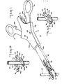
- an illustrative embodiment of the clip applying apparatus 10 of this invention includes main body 12 in which two ring handles 14 and 16 are pivotally mounted to project out of the rearward or proximal end of the main body. Ring handles 14 and 16 are designed to receive, respectively, the thumb and a finger of one hand of the operator of the instrument. Instrument 10 is therefore operable entirely by one hand like a pair of scissors.
- Main body 12 is made up of two parts 12a and 12b (see Figure 7) which may be held together in any conventional manner such as by a suitable adhesive.
- a longitudinal shaft assembly 18 is mounted on body 12 and extends in the forward or distal direction from the body. Shaft assembly 18 terminates at the distal end of the apparatus in a pair of jaws 20, 22.
- jaws 20 and 22 are placed around the body tissue (e.g., blood vessel 24) to be clipped. Ring handles 14 and 16 are then squeezed together by the operator. This causes a clip 26 ( Figure 13) to be advanced along shaft assembly 18 and positioned in jaws 20, 22 with one arm of the clip in each jaw. Continued squeezing of the ring handles causes an outer sleeve portion of shaft assembly 18 to move distally relative to jaws 20, 22 and to thereby squeeze the jaws together. This closes the clip on the body tissue. When ring handles 14, 16 are subsequently released, jaws 20, 22 reopen and release the clipped tissue as shown in Figure 14. The instrument is now ready to begin another cycle of operation.
- Each clip 26 includes a base 30 and two arms 32, 34 extending from respective opposite ends of the base.
- the base and arms of the clip lie in a common plane.
- the clips are made so that the normally free end portions 36, 38 of the arms are resiliently biased apart, as shown for example in Figure 12.
- the outer periphery of the base portion of each clip includes two laterally extending lugs 42, 44, each of which is adjacent a respective end of base 30.
- lugs 42, 44 could be respectively located along arms 32, 34.
- the inner periphery of the normally free end portion 36, 38 of each arm includes a slot 46, 48, respectively.
- each clip When the physically separate and individual clips are associated with one another in a train, as shown for example in Figure 15, the lugs 42, 44 of each clip are respectively releasably received in and engaged by the slots 46, 48 in the immediately following clip.
- the arms of each clip are prevented from spreading farther apart by the surrounding structure of the instrument. Accordingly, when the forwardmost clip in the train is pushed in the distal direction as described in detail below, all the succeeding clips in the train are pulled along at the same time.
- the normally free end portions 36, 38 of the arms of each clip also include complementary latching elements 32a and 32c on arm 32 and 34a and 34c on arm 34.
- latching elements 32a and 34a overlap and interlock with one another, and latching elements 32c and 34c similarly overlap and interlock with one another. Once these latching elements interlock, they hold the clip closed.
- the sense or direction of the overlap of latching elements 32a and 34a is opposite to the sense or direction of the overlap of latching elements 32c and 34c.
- latching element 32a is above latching element 34a, but latching element 32c is below latching element 34c. This makes the clip highly resistant to inadvertent reopening by helping to keep arms 32 and 34 co-planar.
- handles 14 and 16 are pivotally mounted on main body 12 by means of a substantially cylindrical knob 52 at the distal end of each ring handle, in cooperation with cylindrical sockets 53 in the interior of main body 12.
- a pin or screw 54 may be located coaxially in each of the above-described pivotal connections so as to extend through main body 12 and the associated knob 52 to help maintain handles 14 and 16 in main body 12.
- Pivotally mounted links 56 and 58 are connected between handles 14 and 16, respectively, and the proximal end of sleeve 60.
- Link 56 is pivotally connected to handle 14 by pin 62; link 58 is pivotally connected to handle 16 by pin 64; and both links are pivotally connected to sleeve 60 by pin 66.
- Sleeve 60 is mounted for longitudinal reciprocal motion relative to housing 12. When handles 14 and 16 are squeezed together, links 56 and 58 drive sleeve 60 in the distal direction.
- Sleeve 60 is resiliently biased in the proximal direction by compression coil spring 68, which is compressed between surface 70 ( Figures 3 and 4) inside housing 12 and the proximal end of aperture 72 in sleeve 60.
- the proximal resilient bias of sleeve 60 also resiliently biases handles 14 and 16 apart. The outward motion of handles 14 and 16 is stopped by contact of the handle shafts with the sides of main body housing 12 as shown in Figure 3.
- Spring 68 is thus the main return spring of the instrument.
- sleeve 60 is basically a channel-shaped member, preferably made of metal. Inside the channel defined by sleeve 60 is jaw member 74, which is fixedly mounted relative to housing 12 by cooperation of housing lugs 76a and 76b with apertures 78a and 78b in the proximal end portion of jaw member 74. Lugs 76 pass freely through the distal portion of aperture 72 in sleeve 60. The distal end portion of jaw member 74 is bifurcated to define two spaced, substantially parallel arms 82 and 84. Jaws 20 and 22 are respectively mounted on the distal ends of arms 82 and 84. Jaw member 74 is preferably made of resilient metal so that arms 82 and 84 can be deflected toward one another as described in detail below, and so that when the force on them is released, they will resume their original spacing.
- clip train container 90 Fixedly mounted on the upper surface of jaw member 74 is clip train container 90.
- clip train container 90 is a C-shaped channel member whose longitudinal axis is aligned with the longitudinal axis of jaw member 74.
- the channel of clip train container 90 contains a plurality of clips 26 arranged in an interlocking linear array or train as described in detail above (see again Figure 15).
- the normally free ends 36, 38 of each clip point in the distal direction, and the train of clips is aligned with the longitudinal axis of clip train container 90.
- Clip train container 90 has a raised dimple or detent 92 near the distal end of the channel which helps to uncouple the distal-most clip from the clip train as described in detail below.
- Clip train container 90 also has a leaf spring portion 94 which projects up into the channel and which acts as a pawl member to substantially prevent the clip train from moving in the proximal direction.
- Clips can move past pawl spring 94 in the distal direction by depressing the pawl spring as they pass. However, clips can not move back in the proximal direction because the distal end of pawl spring 94 will contact the base 30 of a clip approaching the spring from the distal side and prevent further proximal motion of the clip (see Figures 23 and 24).
- the clips are prevented from inadvertently falling out of the distal end of container 90 by inwardly biased leaf spring elements 96 ( Figure 8) near the distal end of container 90.
- the upper portion of clip train container 90 is open to permit pusher finger 102 at the distal end of pusher member 100 to extend down into container 90 and to contact the base 30 of the distal-most clip in container 90.
- Pusher member 100 is mounted over clip train container 90 for longitudinal reciprocal motion relative thereto.
- Pusher member 100 is coupled to channel member 60 by means of coupler 110 and compression coil spring 120.
- Coupler 110 fits in a proximal portion of channel 60 and includes a pair of laterally extending lugs 112a and 112b which respectively fit in slots 114a and 114b in channel member 60 so that coupler 110 reciprocates longitudinally with channel member 60.
- the proximal end of pusher member 100 includes downwardly extending finger 104, which fits into coupler 110 on the proximal side of transverse bar 116 in the coupler. Finger 104 is resiliently biased in the distal direction against transverse bar 116 by compression coil spring 120, which also fits in coupler 110 and acts between the proximal end of the coupler and finger 104.
- Spring guard 122 below coupler 110 keeps spring 120 in coupler 110. Aperture 124 in spring guard 122 allows the extreme lower end of finger 104 on pusher member 100 to enter aperture 78c in jaw member 74 (see Figure 4).
- the above-described coupling between pusher member 100 and channel member 60 operates as follows: As channel member 60 moves in the distal direction in response to operation of handles 14 and 16, coupler 110 and spring 120 cause pusher member 100 to move with channel member 60 until finger 104 contacts the distal end 78d of aperture 78c in jaw member 74. Thereafter, further distal motion of pusher member 100 is prevented by this contact between finger 104 and surface 78d. Channel member 60 can continue to move in the distal direction, but pusher member 100 is stopped. Spring 120 compresses to permit this differential motion of elements 60 and 100. When handles 14 and 16 are released, channel member 60 moves back in the proximal direction and pusher member 100 is pulled back with member 60 by contact of transverse bar 116 with finger 104.
- Shaft assembly 18 is covered by cover 130 (Figure 8) which is secured to channel member 60 by cooperation of tongues 132 on cover 130 and apertures 134 on channel member 60 (see Figure 10).
- Figures 15-24 show the apparatus before squeezing of the handles begins.
- Channel member 60, coupler 110, and pusher member 100 are all in their proximal-most positions.
- Pusher finger 102 is on the proximal side of the distal-most clip 26 in the clip train.
- Jaws 20 and 22 are open and positioned around the body tissue 24 to be clipped.
- FIG. 17 shows the distal-most clip just after uncoupling from the clip train as described above. It should be noted that detent 92 is sized and positioned so that it retards the clip train only when the distal-most clip is to be uncoupled. At other positions of the clip train, detent 92 does not contact any portion of the train.
- the distal-most clip could be uncoupled by allowing the arms of the next-to-distal-most clip to spread apart. This could be accomplished by spreading apart the side walls of clip train container 90 at the point at which uncoupling is desired.
- Figures 19 and 20 show the apparatus after still further squeezing of handles 14 and 16. Elements 60, 110, and 100 have advanced still farther in the distal direction. Pusher finger 102 has now pushed distal-most clip 26 completely out of clip train container 90 and fully into jaws 20 and 22. The clip is prevented from falling out of the end of jaws 20 and 22 by inwardly projecting clip stops 146 and 148 near the distal ends of the jaws. The remaining clips in the clip train have remained stationary since the distal-most clip was uncoupled from the train as shown in Figure 17 because the next-to-distal-most clip is captured between detent 92 and pawl spring element 94.
- channel member 60 The distal end of channel member 60 is just about to contact diverging cam surfaces 152 and 154 on jaws 20 and 22 respectively. Also, the lower end of finger 104 on pusher member 100 has just contacted the distal end 78d of aperture 78c in jaw member 74. This prevents further distal motion of pusher member 100 as squeezing of handles 14 and 16 continues.
- FIG. 21 and 22 The condition of the apparatus in response to the final portion of the squeezing of handles 14 and 16 1 is shown in Figures 21 and 22. Elements 60 and 110 continue to move in the distal direction, but pusher member 10 0 is prevented from srch further distal motion by contact of finger 104 with surface 78d. Accordingly, no further distal motion of the distal-most clip occurs.
- the distal end of channel member 60 engages cam surfaces 152 and 154 on jaw member 74 and cooperates with those surfaces to squeeze jaws 20 and 22 toward one another. This squeezes the arms of the distal-most clip together until clip elements 32a, 32c, 34a, and 34c interlock to hold the clip closed around body tissue 24.
- the arms of the clip may include apertures 32b and 34b, respectively, to provide some relief of the pressure on the tissue. However, the clip preferably applies sufficient pressure to the tissue to produce hemostasis without-causing undue tissue damage.
- pusher finger 102 is limited to motion between (1) a proximal-most position in which the pusher finger is between the distal-most clip and the next-to-distal-most clip in the clip train at the location at which the clip train was left when the previously distal-most clip was uncoupled from the train, and (2) a distal-most position in which the distal-most 0 clip has been fully pushed into jaws 20 and 22.
- the proximal-most position of pusher finger 102 is established by contact of ring handles 14 and 16 with main body housing 12 as shown in Figure 3.
- the distal-most position of pusher finger 102 is established by contact between finger 104 and surface 78d. In this way one, and only one, clip is pushed into jaws 20 and 22 during each operating cycle of the apparatus.
- Clips 26 may have various sizes depending on their intended use. Typical clips may be about 10 mm long and 8 mm wide before being closed. Much smaller clips may be used for certain applications in microsurgery. Larger clips may be used for other purposes such as closing vas deferens and oviducts.
- the clip applying apparatus is sized appropriately for the clips it is to apply.
- clips 26 may be either metal or plastic, and may be either biologically absorbable or nonabsorbable.
- Preferred absorbable polymers include homopolymers and copolymers of glycolide, lactide and p-dioxanone.
- Preferred nonabsorbable polymers include nylon, polyester, and polypropylene.
- Typical metals include aluminum, magnesium, stainless steel, tantalum, and various alloys of these materials, some of which may also be biologically absorbable.
- the provision of apparatus which advances a clip train by pushing on the distal-most staple in the train greatly facilitates use of plastic clips because it avoids the problems associated with attempting to push a line of plastic clips from the rear. If pushed from the rear, a line of such clips may tend to buckle and therefore bind in the apparatus. Also, because of the nature of the plastic clip material, the line of clips may foreshorten when pushed from the rear, thereby making it difficult or impossible to maintain the clips in registration with the surrounding apparatus for proper progression of one clip into the jaws during each operating cycle of the appratus.
- the entire apparatus can be made economically disposable after use in a single surgical procedure or after the supply of clips in clip train container 90 is exhausted. In this way all difficulty and expense associated with cleaning, sterilizing, and reloading the apparatus for reuse can be entirely avoided.
- channel member 60 acts as a reciprocating sleeve to close jaws 20 and 22, most of the operating elements in the apparatus must transmit only tension and compression forces, not bending moments as in instruments which operate like scissors or pliers.
- the instrument can therefore be made with an extremely light and slender construction.
- the relatively small amounts of material required, as well as the simplicity of the design of the instrument make it economical to produce the instrument as a disposable item if desired.
- main body 12 and much of handles 14 and 16 can be made of inexpensive plastic materials.
- the apparatus can be made with a permanent and reusable construction if desired.
- the in-line feeding of the clips and the slender construction of shaft assembly 18 permit a clear view of the jaws at all times. This is highly desirable in delicate surgical procedures.
Abstract
Description
- This invention relates to hemostatic surgical clip applying methods and apparatus, and to surgical clips for use therein. More particularly, the invention relates to hemostatic surgical clip applying methods and apparatus in which clips contained in a clip applying instrument are automatically fed one at a time to the clip closing portion of the instrument as the instrument is operated.
- In-line feeding of the clips in surgical clip applying apparatus is highly desirable because it eliminates the need for a bulky clip magazine near the distal end of the instrument. Such a magazine may obstruct the surgeon's view of the jaws of the instrument when the instrument is being used to apply hemostatic clips to body tissue in a surgical procedure. Several techniques for in-line surgical clip feeding have been developed, but many of these techniques tend to be relatively complicated and to require a large number of parts or elements to advance the clips to the clip closing portion of the apparatus.
- It is therefore an object of this invention to improve and simplify surgical clip applying methods and apparatus.
- It is a more particular object of this invention to provide surgical clip applying methods and apparatus with improved and simplified in-line feeding of the clips to the clip closing portion of the apparatus.
- These and other objects of the invention are accomplished in accordance with the principles of the invention by providing surgical clips which releasably couple together to form a linear array or train. The clip train is slidably disposed along the longitudinal axis of a clip applying instrument. A pusher, reciprocally mounted in the clip applying instrument, contacts the forwardmost clip in the train and pushes it in the distal direction toward the clip closing jaws of the instrument. The remaining clips in the train are pulled along with the forwardmost clip until, as the forwardmost clip is entering the jaws, that clip is uncoupled from the remaining clips in the train and seated in the jaws. The jaws then operate to close the clip around the body tissue to be clipped. When the pusher is subsequently released, the jaws release the closed clip. The pusher also retracts to the proximal side of the next clip, which is now the forwardmost clip in the clip train. The instrument is ready to repeat its operating cycle.
- Although the clips may be made of biologically acceptable metal, they are preferably made of biologically acceptable plastic, most preferably of biologically absorbable plastic material. Plastic clips may be preferred because, if left in the body after the surgical procedure, they do not degrade the quality of subsequent radiographs (X-rays) the way metal clips may. Biologically absorbable plastic clips have the further advantage that they are absorbed by the body after the clipped tissue has healed. Possibly undesirable migration of the clips in the body during the months and years following surgery is thereby avoided. If the clips are made of plastic (whether biologically absorbable or not), the normally free end portions of the arms of each clip preferably have mutually interlocking elements for holding the arms of the clip together after it has been closed as described above.
- Further features of the invention, its nature and various advantages will be more apparent from the accompanying drawing and the following detailed description of the invention.
-
- Figure 1 is a perspective view of an illustrative embodiment of the surgical clip applying apparatus of this invention.
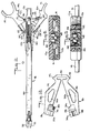
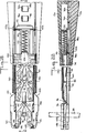
- Figure 2 is a top plan view of the apparatus of Figure 1 with some of the upper parts removed to reveal some of the interior elements.
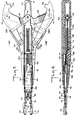
- Figure 3 is a view similar to Figure 2 but with several elements cut away to reveal additional interior elements.
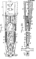
- Figure 4 is an elevational sectional view taken along the line 4-4 in Figure 3.
- Figures 5 and 6 are cross sectional views respectively taken along the lines 5-5 and 6-6 in Figure 3.
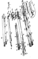
- Figure 7 is a partly exploded perspective view of the apparatus of Figures 1-6.
- Figure 8 is a further exploded perspective view of a portion of the apparatus of Figure 7.
- Figure 9 is an exploded elevational view of the apparatus of Figure 8.
- Figures 10 and 11 are cross sectional views respectively taken along the lines 10-10 and 11-11 in Figure 9.
- Figure 12 is an enlarged plan view of an illustrative surgical clip for use in the apparatus of Figures 1-11.
- Figure 13 is a perspective view of the clip of Figure 12 in position to be applied to body tissue. The clip applying apparatus which surrounds the clip during application of the clip to body tissue is not shown in Figure 13 in order to show the clip itself most clearly.
- Figure 14 is a view similar to Figure 13 but showing the clip applied to the body tissue.
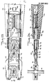
- Figures 15, 17, 19, 21, and 23 are a series of views similar to a portion of Figure 3 depicting the operating sequence of the apparatus.
- Figures 16, 18, 20, 22, and 24 are sectional views respectively taken along the lines 16-16, 18-18, 20-20, 22-22, and 24-24 in Figures 15, 17, 19, 21, and 23.
- As shown in Figure 1, an illustrative embodiment of the
clip applying apparatus 10 of this invention includesmain body 12 in which tworing handles Ring handles Instrument 10 is therefore operable entirely by one hand like a pair of scissors.Main body 12 is made up of twoparts 12a and 12b (see Figure 7) which may be held together in any conventional manner such as by a suitable adhesive. - A
longitudinal shaft assembly 18 is mounted onbody 12 and extends in the forward or distal direction from the body.Shaft assembly 18 terminates at the distal end of the apparatus in a pair ofjaws jaws Ring handles shaft assembly 18 and positioned injaws shaft assembly 18 to move distally relative tojaws ring handles jaws - Although it will be apparent to those skilled in the art that clips of other materials such as metal can be employed, the illustrative embodiment will be described for the most part in the context of the application of plastic clips.
- An illustrative
surgical clip 26 is shown in Figures 12-14, and a train of such clips is visible, for example, in Figure 15. Each clip includes abase 30 and twoarms free end portions lugs base 30. Alternatively,lugs arms free end portion slot lugs slots - The normally
free end portions complementary latching elements arm arm 34. When the arms of the clip are squeezed together as shown in Figure 14, latchingelements elements elements elements clip 26 is viewed from above as in Figure 14, latchingelement 32a is above latchingelement 34a, but latchingelement 32c is below latchingelement 34c. This makes the clip highly resistant to inadvertent reopening by helping to keeparms - Considering now the construction of
instrument 10 in more detail with reference to Figures 2 and 3, handles 14 and 16 are pivotally mounted onmain body 12 by means of a substantiallycylindrical knob 52 at the distal end of each ring handle, in cooperation withcylindrical sockets 53 in the interior ofmain body 12. If desired, a pin or screw 54 may be located coaxially in each of the above-described pivotal connections so as to extend throughmain body 12 and the associatedknob 52 to help maintainhandles main body 12. Pivotally mountedlinks handles sleeve 60.Link 56 is pivotally connected to handle 14 bypin 62;link 58 is pivotally connected to handle 16 bypin 64; and both links are pivotally connected tosleeve 60 bypin 66.Sleeve 60 is mounted for longitudinal reciprocal motion relative tohousing 12. When handles 14 and 16 are squeezed together, links 56 and 58drive sleeve 60 in the distal direction. -
Sleeve 60 is resiliently biased in the proximal direction bycompression coil spring 68, which is compressed between surface 70 (Figures 3 and 4) insidehousing 12 and the proximal end ofaperture 72 insleeve 60. The proximal resilient bias ofsleeve 60 also resiliently biases handles 14 and 16 apart. The outward motion ofhandles main body housing 12 as shown in Figure 3.Spring 68 is thus the main return spring of the instrument. - As is best seen in Figure 8,
sleeve 60 is basically a channel-shaped member, preferably made of metal. Inside the channel defined bysleeve 60 isjaw member 74, which is fixedly mounted relative tohousing 12 by cooperation ofhousing lugs apertures jaw member 74. Lugs 76 pass freely through the distal portion ofaperture 72 insleeve 60. The distal end portion ofjaw member 74 is bifurcated to define two spaced, substantiallyparallel arms Jaws arms Jaw member 74 is preferably made of resilient metal so thatarms - Fixedly mounted on the upper surface of
jaw member 74 isclip train container 90. As best seen in Figure 10,clip train container 90 is a C-shaped channel member whose longitudinal axis is aligned with the longitudinal axis ofjaw member 74. The channel ofclip train container 90 contains a plurality ofclips 26 arranged in an interlocking linear array or train as described in detail above (see again Figure 15). The normally free ends 36, 38 of each clip point in the distal direction, and the train of clips is aligned with the longitudinal axis ofclip train container 90.Clip train container 90 has a raised dimple ordetent 92 near the distal end of the channel which helps to uncouple the distal-most clip from the clip train as described in detail below.Clip train container 90 also has aleaf spring portion 94 which projects up into the channel and which acts as a pawl member to substantially prevent the clip train from moving in the proximal direction. Clips can movepast pawl spring 94 in the distal direction by depressing the pawl spring as they pass. However, clips can not move back in the proximal direction because the distal end ofpawl spring 94 will contact thebase 30 of a clip approaching the spring from the distal side and prevent further proximal motion of the clip (see Figures 23 and 24). The clips are prevented from inadvertently falling out of the distal end ofcontainer 90 by inwardly biased leaf spring elements 96 (Figure 8) near the distal end ofcontainer 90. - As best seen in Figure 8, the upper portion of
clip train container 90 is open to permitpusher finger 102 at the distal end ofpusher member 100 to extend down intocontainer 90 and to contact thebase 30 of the distal-most clip incontainer 90.Pusher member 100 is mounted overclip train container 90 for longitudinal reciprocal motion relative thereto.Pusher member 100 is coupled tochannel member 60 by means ofcoupler 110 andcompression coil spring 120.Coupler 110 fits in a proximal portion ofchannel 60 and includes a pair of laterally extendinglugs 112a and 112b which respectively fit in slots 114a and 114b inchannel member 60 so thatcoupler 110 reciprocates longitudinally withchannel member 60. The proximal end ofpusher member 100 includes downwardly extendingfinger 104, which fits intocoupler 110 on the proximal side oftransverse bar 116 in the coupler.Finger 104 is resiliently biased in the distal direction againsttransverse bar 116 bycompression coil spring 120, which also fits incoupler 110 and acts between the proximal end of the coupler andfinger 104.Spring guard 122 belowcoupler 110 keepsspring 120 incoupler 110.Aperture 124 inspring guard 122 allows the extreme lower end offinger 104 onpusher member 100 to enteraperture 78c in jaw member 74 (see Figure 4). - The above-described coupling between
pusher member 100 andchannel member 60 operates as follows: Aschannel member 60 moves in the distal direction in response to operation ofhandles coupler 110 andspring 120cause pusher member 100 to move withchannel member 60 untilfinger 104 contacts thedistal end 78d ofaperture 78c injaw member 74. Thereafter, further distal motion ofpusher member 100 is prevented by this contact betweenfinger 104 andsurface 78d.Channel member 60 can continue to move in the distal direction, butpusher member 100 is stopped.Spring 120 compresses to permit this differential motion ofelements channel member 60 moves back in the proximal direction andpusher member 100 is pulled back withmember 60 by contact oftransverse bar 116 withfinger 104. -
Shaft assembly 18 is covered by cover 130 (Figure 8) which is secured to channelmember 60 by cooperation oftongues 132 oncover 130 andapertures 134 on channel member 60 (see Figure 10). - The sequence of operation of the apparatus in response to squeezing and then releasing
handles Channel member 60,coupler 110, andpusher member 100 are all in their proximal-most positions.Pusher finger 102 is on the proximal side of thedistal-most clip 26 in the clip train.Jaws body tissue 24 to be clipped. - In Figures 17 and 18, squeezing of
handles channel member 60 has moved in the distal direction, carrying with itcoupler 110 andpusher member 100.Pusher finger 102 has contacted thebase 30 of thedistal-most clip 26 in the clip train, thereby advancing that clip and all the other clips in the distal direction. When the apparatus reaches the stage shown in Figures 17 and 18, the distal-most clip has passeddetent 92, is nearly out ofclip train container 90, and has begun to enterjaws body tissue 24 to be clipped.Jaws longitudinal slots clip arms jaws lugs detent 92 is sized and positioned so that it retards the clip train only when the distal-most clip is to be uncoupled. At other positions of the clip train,detent 92 does not contact any portion of the train. - As a possible alternative to uncoupling the distal-most clip by squeezing the arms of that clip together, the distal-most clip could be uncoupled by allowing the arms of the next-to-distal-most clip to spread apart. This could be accomplished by spreading apart the side walls of
clip train container 90 at the point at which uncoupling is desired. - Figures 19 and 20 show the apparatus after still further squeezing of
handles Elements Pusher finger 102 has now pusheddistal-most clip 26 completely out ofclip train container 90 and fully intojaws jaws detent 92 andpawl spring element 94. The distal end ofchannel member 60 is just about to contact diverging cam surfaces 152 and 154 onjaws finger 104 onpusher member 100 has just contacted thedistal end 78d ofaperture 78c injaw member 74. This prevents further distal motion ofpusher member 100 as squeezing ofhandles - The condition of the apparatus in response to the final portion of the squeezing of
handles Elements pusher member 100 is prevented from srch further distal motion by contact offinger 104 withsurface 78d. Accordingly, no further distal motion of the distal-most clip occurs. The distal end ofchannel member 60 engages cam surfaces 152 and 154 onjaw member 74 and cooperates with those surfaces to squeezejaws clip elements body tissue 24. The arms of the clip may includeapertures 32b and 34b, respectively, to provide some relief of the pressure on the tissue. However, the clip preferably applies sufficient pressure to the tissue to produce hemostasis without-causing undue tissue damage. - The clip-applying stroke of the instrument is now complete.
Handles proximal projection 12c ofmain body 12. When the operator releases the squeezing pressure onhandles main return spring 68drives channel member 60 back in the proximal direction. This allowsjaws pusher member 100 back so thatpusher finger 102 rides up over thebase 30 of what is now the distal-most clip inclip train container 90. The clip train is prevented from moving in the proximal direction bypawl spring element 94 in the bottom ofclip train container 90. When handles 14 and 16 have been fully released, the apparatus has returned to the condition shown in Figures 15 and 16 and is ready to begin another cycle of operation. Thuspusher finger 102 is limited to motion between (1) a proximal-most position in which the pusher finger is between the distal-most clip and the next-to-distal-most clip in the clip train at the location at which the clip train was left when the previously distal-most clip was uncoupled from the train, and (2) a distal-most position in which thedistal-most 0 clip has been fully pushed intojaws pusher finger 102 is established by contact of ring handles 14 and 16 withmain body housing 12 as shown in Figure 3. The distal-most position ofpusher finger 102 is established by contact betweenfinger 104 andsurface 78d. In this way one, and only one, clip is pushed intojaws -
Clips 26 may have various sizes depending on their intended use. Typical clips may be about 10 mm long and 8 mm wide before being closed. Much smaller clips may be used for certain applications in microsurgery. Larger clips may be used for other purposes such as closing vas deferens and oviducts. The clip applying apparatus is sized appropriately for the clips it is to apply. - As mentioned above, clips 26 may be either metal or plastic, and may be either biologically absorbable or nonabsorbable. Preferred absorbable polymers include homopolymers and copolymers of glycolide, lactide and p-dioxanone. Preferred nonabsorbable polymers include nylon, polyester, and polypropylene. Typical metals include aluminum, magnesium, stainless steel, tantalum, and various alloys of these materials, some of which may also be biologically absorbable.
- The provision of apparatus which advances a clip train by pushing on the distal-most staple in the train greatly facilitates use of plastic clips because it avoids the problems associated with attempting to push a line of plastic clips from the rear. If pushed from the rear, a line of such clips may tend to buckle and therefore bind in the apparatus. Also, because of the nature of the plastic clip material, the line of clips may foreshorten when pushed from the rear, thereby making it difficult or impossible to maintain the clips in registration with the surrounding apparatus for proper progression of one clip into the jaws during each operating cycle of the appratus.
- Advantageously, the entire apparatus can be made economically disposable after use in a single surgical procedure or after the supply of clips in
clip train container 90 is exhausted. In this way all difficulty and expense associated with cleaning, sterilizing, and reloading the apparatus for reuse can be entirely avoided. Becausechannel member 60 acts as a reciprocating sleeve to closejaws main body 12 and much ofhandles shaft assembly 18 permit a clear view of the jaws at all times. This is highly desirable in delicate surgical procedures. - It is to be understood that the individual clips and/or clip train of this invention are usable with clip applying instruments other than the particular one described above. For example, in my concurrently filed, commonly assigned, U.S. patent application Serial No. 429,249 entitled "Surgical Clip Applying Apparatus Having Fixed Jaws" (Docket No. USSC 1030), which is hereby incorporated by reference herein, clip applying apparatus is shown which has fixed jaws and which may use the clip train of this invention (see especially Figures 1-17 of that application). Other modifications of the particular embodiments shown and described herein are also within the scope and spirit of the invention. For example, other types of actuator elements, such as a pistol grip and trigger arrangement, could be substituted for ring handles 14 and 16 in the apparatus of Figures 1-24 herein.
Claims (6)
Priority Applications (1)
| Application Number | Priority Date | Filing Date | Title |
|---|---|---|---|
| AT86114506T ATE63047T1 (en) | 1982-09-30 | 1983-09-28 | DEVICE FOR ATTACHING CLAMPS. |
Applications Claiming Priority (2)
| Application Number | Priority Date | Filing Date | Title |
|---|---|---|---|
| US06/429,250 US4512345A (en) | 1982-09-30 | 1982-09-30 | Surgical clip applying apparatus, and clips and clip train for use therein |
| US429250 | 1982-09-30 |
Related Parent Applications (1)
| Application Number | Title | Priority Date | Filing Date |
|---|---|---|---|
| EP83401901.0 Division | 1983-09-28 |
Publications (3)
| Publication Number | Publication Date |
|---|---|
| EP0220643A2 true EP0220643A2 (en) | 1987-05-06 |
| EP0220643A3 EP0220643A3 (en) | 1987-08-26 |
| EP0220643B1 EP0220643B1 (en) | 1991-05-02 |
Family
ID=23702451
Family Applications (2)
| Application Number | Title | Priority Date | Filing Date |
|---|---|---|---|
| EP86114506A Expired - Lifetime EP0220643B1 (en) | 1982-09-30 | 1983-09-28 | Surgical clip applying apparatus |
| EP83401901A Expired EP0105797B1 (en) | 1982-09-30 | 1983-09-28 | Surgical clip applying methods and apparatus, and clips and clips train for use therein |
Family Applications After (1)
| Application Number | Title | Priority Date | Filing Date |
|---|---|---|---|
| EP83401901A Expired EP0105797B1 (en) | 1982-09-30 | 1983-09-28 | Surgical clip applying methods and apparatus, and clips and clips train for use therein |
Country Status (10)
| Country | Link |
|---|---|
| US (1) | US4512345A (en) |
| EP (2) | EP0220643B1 (en) |
| JP (1) | JPS59501656A (en) |
| AT (2) | ATE28973T1 (en) |
| AU (2) | AU563033B2 (en) |
| BR (1) | BR8307535A (en) |
| CA (2) | CA1211332A (en) |
| DE (3) | DE3348045C2 (en) |
| GB (2) | GB2135584B (en) |
| WO (1) | WO1984001279A1 (en) |
Cited By (13)
| Publication number | Priority date | Publication date | Assignee | Title |
|---|---|---|---|---|
| EP0406724A1 (en) * | 1989-07-03 | 1991-01-09 | Edward Weck Incorporated | Automatic hemostatic clip applicator |
| EP0469524A1 (en) * | 1990-07-30 | 1992-02-05 | JOHNSON & JOHNSON PROFESSIONAL, INC. | Surgical clip and surgical clip applier with reciprocating sleeve and dual rachet mechanism |
| EP0515393A1 (en) * | 1989-12-26 | 1992-12-02 | NAKAO, Naomi | Endoscopic stapling device and method |
| EP0738499A2 (en) * | 1989-07-18 | 1996-10-23 | United States Surgical Corporation | Apparatus and method for applying surgical clips in laparoscopic or endoscopic procedures |
| WO2001087196A1 (en) * | 2000-05-17 | 2001-11-22 | Femcare (Cyprus) Limited | Medical clips |
| EP1462061A2 (en) * | 2003-03-25 | 2004-09-29 | Ethicon Endo-Surgery, Inc. | Passive surgical clip |
| WO2011094700A1 (en) | 2010-01-29 | 2011-08-04 | Advanced Bariatric Technology, Llc | Surgical clamp and surgical clamp installation tool |
| US8100926B1 (en) | 1999-07-15 | 2012-01-24 | Femcare Limited | Surgical clip |
| US8920305B2 (en) | 2007-01-19 | 2014-12-30 | Advanced Bariatric Technology, Llc | Vertically oriented band for stomach |
| US10420664B2 (en) | 2014-08-26 | 2019-09-24 | Advanced Bariatric Technology, Llc | Bariatric clamp with suture portions, magnetic inserts and curvature |
| US10456141B2 (en) | 2012-08-09 | 2019-10-29 | Advanced Bariatric Technology, Llc | Polymer overmolded bariatric clamp and method of installing |
| US10932938B2 (en) | 2017-07-24 | 2021-03-02 | Advanced Bariatric Technology, Llc | Clamp installation tool |
| US11337839B2 (en) | 2016-07-07 | 2022-05-24 | Advanced Bariatric Technology, Llc | Inflatable bariatric clamp |
Families Citing this family (208)
| Publication number | Priority date | Publication date | Assignee | Title |
|---|---|---|---|---|
| US4556058A (en) * | 1983-08-17 | 1985-12-03 | United States Surgical Corporation | Apparatus for ligation and division with fixed jaws |
| US4576165A (en) * | 1984-01-23 | 1986-03-18 | United States Surgical Corporation | Surgical ligation and cutting device with safety means |
| US4616650A (en) * | 1984-07-27 | 1986-10-14 | United States Surgical Corporation | Apparatus for applying surgical clips |
| US4598711A (en) * | 1984-08-09 | 1986-07-08 | American Cyanamid Company | Surgical instrument |
| GB8611452D0 (en) * | 1986-05-10 | 1986-06-18 | Femcare Ltd | Sexual sterilation device |
| US4796627A (en) * | 1986-08-26 | 1989-01-10 | Tucker Wilson H | Clip applicator and spreadable clips for use therein |
| US4850355A (en) * | 1987-04-06 | 1989-07-25 | Richard-Allan Medical Industries, Inc. | Hemostatic clip applicator for applying multiple hemostatic clips |
| US4822348A (en) * | 1987-05-13 | 1989-04-18 | Donn Casey | Surgical clips |
| US5366459A (en) * | 1987-05-14 | 1994-11-22 | Inbae Yoon | Surgical clip and clip application procedures |
| US5030226A (en) * | 1988-01-15 | 1991-07-09 | United States Surgical Corporation | Surgical clip applicator |
| US5100420A (en) * | 1989-07-18 | 1992-03-31 | United States Surgical Corporation | Apparatus and method for applying surgical clips in laparoscopic or endoscopic procedures |
| US5197970A (en) * | 1988-01-15 | 1993-03-30 | United States Surgical Corporation | Surgical clip applicator |
| US5383881A (en) * | 1989-07-18 | 1995-01-24 | United States Surgical Corporation | Safety device for use with endoscopic instrumentation |
| US5049152A (en) * | 1989-03-07 | 1991-09-17 | Richard-Allan Medical Industries | Hemostatic clip applicator |
| FR2637489A1 (en) * | 1988-10-07 | 1990-04-13 | Lachkar Alain | AUTOMATIC CLIPS CLIP |
| AU625522B2 (en) * | 1989-05-24 | 1992-07-16 | Atrist Pty. Ltd. | Suturing devices |
| US5382254A (en) * | 1989-07-18 | 1995-01-17 | United States Surgical Corporation | Actuating handle for surgical instruments |
| US5156609A (en) * | 1989-12-26 | 1992-10-20 | Nakao Naomi L | Endoscopic stapling device and method |
| US5342394A (en) * | 1990-05-16 | 1994-08-30 | Olympus Optical Co., Ltd. | Apparatus for blocking a vein branch and method of blocking a vein branch |
| DE4024106C1 (en) * | 1990-07-30 | 1992-04-23 | Ethicon Gmbh & Co Kg, 2000 Norderstedt, De | |
| US5366458A (en) * | 1990-12-13 | 1994-11-22 | United States Surgical Corporation | Latchless surgical clip |
| USRE36720E (en) * | 1990-12-13 | 2000-05-30 | United States Surgical Corporation | Apparatus and method for applying latchless surgical clips |
| CA2060040A1 (en) * | 1991-02-08 | 1992-08-10 | Miguel A. Velez | Surgical staple and endoscopic stapler |
| CA2088883A1 (en) * | 1992-02-13 | 1993-08-14 | David T. Green | Endoscopic ligating instrument |
| US5282811A (en) * | 1992-04-16 | 1994-02-01 | Cook Pacemaker Corporation | Two part surgical ligating clip, applicator and method of use |
| US5342373A (en) * | 1992-09-14 | 1994-08-30 | Ethicon, Inc. | Sterile clips and instrument for their placement |
| US5300081A (en) * | 1992-10-09 | 1994-04-05 | United States Surgical Corporation | Surgical clip applier having clip advancement control |
| CA2107635C (en) * | 1992-10-09 | 1999-08-17 | David T. Green | Surgical clip applier |
| US5868761A (en) * | 1992-10-09 | 1999-02-09 | United States Surgical Corporation | Surgical clip applier |
| CA2133687C (en) * | 1992-10-09 | 2007-03-27 | David T. Green | Surgical clip applier |
| US5725538A (en) * | 1992-10-09 | 1998-03-10 | United States Surgical Corporation | Surgical clip applier |
| US5382255A (en) * | 1993-01-08 | 1995-01-17 | United States Surgical Corporation | Apparatus and method for assembly of surgical instruments |
| EP0622048B1 (en) * | 1993-04-27 | 1997-05-21 | American Cyanamid Company | Automatic laparoscopic ligation clip applicator |
| US5858018A (en) * | 1993-08-25 | 1999-01-12 | Apollo Camera, Llc | Low profile tool for applying spring action ligation clips |
| US5607436A (en) * | 1993-10-08 | 1997-03-04 | United States Surgical Corporation | Apparatus for applying surgical clips |
| US5833700A (en) * | 1995-03-15 | 1998-11-10 | Ethicon Endo-Surgery, Inc. | Sterile occlusion fasteners and instrument and method for their placement |
| US5713912A (en) * | 1995-08-30 | 1998-02-03 | Stress Management, Inc. | Ligating clip having ramp-shaped vessel clamping members and tool for applying same |
| US5700270A (en) * | 1995-10-20 | 1997-12-23 | United States Surgical Corporation | Surgical clip applier |
| US6015417A (en) * | 1996-01-25 | 2000-01-18 | Reynolds, Jr.; Walker | Surgical fastener |
| US5833696A (en) * | 1996-10-03 | 1998-11-10 | United States Surgical Corporation | Apparatus for applying surgical clips |
| US5868759A (en) * | 1997-10-10 | 1999-02-09 | United States Surgical Corporation | Surgical clip applier |
| US6551328B2 (en) * | 1997-11-03 | 2003-04-22 | Symbiosis Corporation | Surgical instrument for invagination and fundoplication |
| US6086600A (en) * | 1997-11-03 | 2000-07-11 | Symbiosis Corporation | Flexible endoscopic surgical instrument for invagination and fundoplication |
| DE19859952A1 (en) * | 1998-08-11 | 2000-02-17 | S & T Marketing Ag Neuhausen | Micro-surgical clamps are produced from a flat strip of metal remaining attached within a recess in the strip |
| US6350269B1 (en) | 1999-03-01 | 2002-02-26 | Apollo Camera, L.L.C. | Ligation clip and clip applier |
| DE19934634C1 (en) * | 1999-07-23 | 2000-12-21 | Aesculap Ag & Co Kg | Surgical clip application instrument has clips in clip magazine fed forwards via reciprocating displacement plate acted on by displacement device at point at least halfway along its length |
| US6592596B1 (en) | 2000-05-10 | 2003-07-15 | Scimed Life Systems, Inc. | Devices and related methods for securing a tissue fold |
| US6494886B1 (en) | 2000-06-22 | 2002-12-17 | Granit Medical Innovation, Inc. | Off-set clamp mechanism and associated method for minimally invasive surgery |
| US20020082621A1 (en) | 2000-09-22 | 2002-06-27 | Schurr Marc O. | Methods and devices for folding and securing tissue |
| US8062314B2 (en) * | 2000-12-06 | 2011-11-22 | Ethicon Endo-Surgery, Inc. | Methods for the endoluminal treatment of gastroesophageal reflux disease (GERD) |
| US20020138086A1 (en) * | 2000-12-06 | 2002-09-26 | Robert Sixto | Surgical clips particularly useful in the endoluminal treatment of gastroesophageal reflux disease (GERD) |
| US7232445B2 (en) * | 2000-12-06 | 2007-06-19 | Id, Llc | Apparatus for the endoluminal treatment of gastroesophageal reflux disease (GERD) |
| US6716226B2 (en) * | 2001-06-25 | 2004-04-06 | Inscope Development, Llc | Surgical clip |
| US20020068945A1 (en) * | 2000-12-06 | 2002-06-06 | Robert Sixto | Surgical clips particularly useful in the endoluminal treatment of gastroesophageal reflux disease (GERD) |
| US7727246B2 (en) * | 2000-12-06 | 2010-06-01 | Ethicon Endo-Surgery, Inc. | Methods for endoluminal treatment |
| US6808491B2 (en) * | 2001-05-21 | 2004-10-26 | Syntheon, Llc | Methods and apparatus for on-endoscope instruments having end effectors and combinations of on-endoscope and through-endoscope instruments |
| US7727248B2 (en) * | 2001-06-25 | 2010-06-01 | Ethicon Endo-Surgery, Inc. | Surgical clip |
| JP2004534591A (en) * | 2001-07-09 | 2004-11-18 | タイコ ヘルスケア グループ エルピー | Right angle clip applier device and method |
| US20050277956A1 (en) * | 2004-06-14 | 2005-12-15 | Francese Jose L | Clip storage for endoscopic clip applier |
| MXPA04009907A (en) * | 2002-04-10 | 2004-12-07 | Tyco Healthcare | Surgical clip applier with high torque jaws. |
| WO2003088850A1 (en) * | 2002-04-15 | 2003-10-30 | Wilson-Cook Medical Inc. | Haemostatic clip device |
| WO2003088822A2 (en) | 2002-04-22 | 2003-10-30 | Tyco Healthcare Group, Lp | Endoscopic surgical clip |
| WO2003088825A2 (en) * | 2002-04-22 | 2003-10-30 | Tyco Healthcare Group, Lp | Endoscopic surgical clip |
| US7678125B2 (en) * | 2002-11-12 | 2010-03-16 | Apollo Camera, L.L.C. | Surgical ligation clip |
| CA2422409C (en) * | 2003-03-07 | 2008-07-29 | Marleen G. Falle | Candle reshaper |
| EP3170459A1 (en) | 2003-03-11 | 2017-05-24 | Covidien LP | Clip applying apparatus with angled jaw |
| US20040193213A1 (en) * | 2003-03-11 | 2004-09-30 | Ernest Aranyi | Clip applying apparatus with curved jaws, and clip |
| US20040193188A1 (en) * | 2003-03-25 | 2004-09-30 | Inscope Development, Llc | Laminated surgical clip |
| US8172870B2 (en) * | 2003-06-09 | 2012-05-08 | Microline Surgical, Inc. | Ligation clip applier |
| AU2004277994B2 (en) * | 2003-09-30 | 2010-04-01 | Boston Scientific Limited | Through the scope tension member release clip |
| US7494461B2 (en) * | 2003-09-30 | 2009-02-24 | Boston Scientific Scimed, Inc. | Through the scope tension member release clip |
| US7572266B2 (en) * | 2003-10-21 | 2009-08-11 | Young Wayne P | Clip applier tool having a discharge configuration |
| AU2004289214B2 (en) * | 2003-11-07 | 2011-05-19 | Scimed Life Systems, Inc. | Endoscopic hemoscopic clipping apparatus |
| US8123757B2 (en) * | 2003-12-31 | 2012-02-28 | Depuy Spine, Inc. | Inserter instrument and implant clip |
| US7799042B2 (en) * | 2004-05-13 | 2010-09-21 | The Cleveland Clinic Foundation | Skin lesion exciser and skin-closure device therefor |
| WO2006034403A2 (en) | 2004-09-23 | 2006-03-30 | Tyco Healthcare Group, Lp | Clip applying apparatus and ligation clip |
| NL1027131C2 (en) * | 2004-09-28 | 2006-03-29 | Cardiall B V | Implantable anchoring system. |
| US7819886B2 (en) | 2004-10-08 | 2010-10-26 | Tyco Healthcare Group Lp | Endoscopic surgical clip applier |
| US9763668B2 (en) | 2004-10-08 | 2017-09-19 | Covidien Lp | Endoscopic surgical clip applier |
| US8409222B2 (en) | 2004-10-08 | 2013-04-02 | Covidien Lp | Endoscopic surgical clip applier |
| JP4783372B2 (en) | 2004-10-08 | 2011-09-28 | タイコ ヘルスケア グループ エルピー | Device for applying a surgical clip |
| EP2641549B1 (en) | 2004-10-08 | 2015-08-12 | Covidien LP | An endoscopic surgical clip applier |
| US8080021B2 (en) * | 2005-01-11 | 2011-12-20 | Boston Scientific Scimed, Inc. | Multiple clip deployment magazine |
| US7738401B2 (en) * | 2005-10-20 | 2010-06-15 | At&T Intellectual Property I, L.P. | System and method for overlaying a hierarchical network design on a full mesh network |
| US20070089433A1 (en) * | 2005-10-20 | 2007-04-26 | Smurfit-Stone Container Enterprises, Inc. | Methods and systems for monitoring a shelf life of a product stored within a container |
| US20070173866A1 (en) * | 2006-01-23 | 2007-07-26 | Tyco Healthcare Group, Lp | Surgical hemostatic clip |
| WO2007106342A2 (en) * | 2006-03-10 | 2007-09-20 | Wilson-Cook Medical Inc. | A clip device and a protective cap for drawing the target tissue into it before the clip is deployed |
| USD625009S1 (en) | 2006-03-24 | 2010-10-05 | Tyco Healthcare Group Lp | Surgical clip applier |
| USD629101S1 (en) | 2006-03-24 | 2010-12-14 | Tyco Healthcare Group Lp | Surgical clip applier |
| AU2007255016A1 (en) * | 2006-06-01 | 2007-12-13 | Cook Medical Technologies Llc | Release mechanisms for a clip device |
| US8425412B2 (en) * | 2006-07-14 | 2013-04-23 | Cook Medical Technologies Llc | Papilla spreader |
| EP1913881B1 (en) | 2006-10-17 | 2014-06-11 | Covidien LP | Apparatus for applying surgical clips |
| WO2008070486A2 (en) * | 2006-12-05 | 2008-06-12 | Wilson-Cook Medical Inc. | Combination therapy hemostatic clip |
| CA2679523C (en) | 2007-03-26 | 2015-06-23 | Tyco Healthcare Group Lp | Endoscopic surgical clip applier |
| CN101677813B (en) | 2007-04-11 | 2012-12-05 | Tyco医疗健康集团 | Surgical clip applier |
| US8579910B2 (en) | 2007-05-18 | 2013-11-12 | DePuy Synthes Products, LLC | Insertion blade assembly and method of use |
| US8056565B2 (en) | 2008-08-25 | 2011-11-15 | Tyco Healthcare Group Lp | Surgical clip applier and method of assembly |
| US8465502B2 (en) | 2008-08-25 | 2013-06-18 | Covidien Lp | Surgical clip applier and method of assembly |
| US20110208212A1 (en) | 2010-02-19 | 2011-08-25 | Zergiebel Earl M | Surgical clip applier |
| US8267944B2 (en) | 2008-08-29 | 2012-09-18 | Tyco Healthcare Group Lp | Endoscopic surgical clip applier with lock out |
| US8585717B2 (en) | 2008-08-29 | 2013-11-19 | Covidien Lp | Single stroke endoscopic surgical clip applier |
| US9358015B2 (en) | 2008-08-29 | 2016-06-07 | Covidien Lp | Endoscopic surgical clip applier with wedge plate |
| US8409223B2 (en) | 2008-08-29 | 2013-04-02 | Covidien Lp | Endoscopic surgical clip applier with clip retention |
| US8906033B2 (en) * | 2009-03-30 | 2014-12-09 | DePuy Synthes Products, LLC | Cervical motion disc inserter |
| DE102009018818A1 (en) * | 2009-04-24 | 2010-10-28 | Aesculap Ag | Surgical instrument for applying ligature clips |
| DE102009018821A1 (en) * | 2009-04-24 | 2010-10-28 | Aesculap Ag | Surgical instrument for applying ligature clips |
| DE102009018820A1 (en) | 2009-04-24 | 2010-10-28 | Aesculap Ag | Magazine with a variety of C-shaped ligature clips |
| DE102009018819A1 (en) * | 2009-04-24 | 2010-10-28 | Aesculap Ag | Surgical instrument for applying ligature clips |
| US8734469B2 (en) | 2009-10-13 | 2014-05-27 | Covidien Lp | Suture clip applier |
| US9186136B2 (en) | 2009-12-09 | 2015-11-17 | Covidien Lp | Surgical clip applier |
| US20110144662A1 (en) * | 2009-12-15 | 2011-06-16 | Mclawhorn Tyler E | Clip devices and systems and methods for deployment |
| US8545486B2 (en) | 2009-12-15 | 2013-10-01 | Covidien Lp | Surgical clip applier |
| US10010336B2 (en) | 2009-12-22 | 2018-07-03 | Cook Medical Technologies, Inc. | Medical devices with detachable pivotable jaws |
| US8545519B2 (en) | 2009-12-22 | 2013-10-01 | Cook Medical Technologies Llc | Medical devices with detachable pivotable jaws |
| BR112012018338B8 (en) | 2009-12-22 | 2021-06-22 | Cook Medical Technologies Llc | medical devices with swivel and detachable claws |
| US8403945B2 (en) | 2010-02-25 | 2013-03-26 | Covidien Lp | Articulating endoscopic surgical clip applier |
| US8968337B2 (en) | 2010-07-28 | 2015-03-03 | Covidien Lp | Articulating clip applier |
| US8403946B2 (en) | 2010-07-28 | 2013-03-26 | Covidien Lp | Articulating clip applier cartridge |
| WO2012051188A2 (en) | 2010-10-11 | 2012-04-19 | Cook Medical Technologies Llc | Medical devices with detachable pivotable jaws |
| EP2627268B8 (en) | 2010-10-11 | 2017-07-26 | Cook Medical Technologies LLC | Medical devices with detachable pivotable jaws |
| WO2012051191A2 (en) | 2010-10-11 | 2012-04-19 | Cook Medical Technologies Llc | Medical devices with detachable pivotable jaws |
| US9011464B2 (en) | 2010-11-02 | 2015-04-21 | Covidien Lp | Self-centering clip and jaw |
| WO2012064643A1 (en) | 2010-11-09 | 2012-05-18 | Cook Medical Technologies Llc | Clip system having tether segments for closure |
| BR112013015246B1 (en) | 2010-12-15 | 2020-11-24 | Cook Medical Technologies Llc | medical device for engaging tissue |
| US9186153B2 (en) | 2011-01-31 | 2015-11-17 | Covidien Lp | Locking cam driver and jaw assembly for clip applier |
| DE102011001706A1 (en) | 2011-03-31 | 2012-10-04 | Aesculap Ag | Surgical clip applicator |
| US9775623B2 (en) | 2011-04-29 | 2017-10-03 | Covidien Lp | Surgical clip applier including clip relief feature |
| US20130131697A1 (en) | 2011-11-21 | 2013-05-23 | Covidien Lp | Surgical clip applier |
| US9364239B2 (en) | 2011-12-19 | 2016-06-14 | Covidien Lp | Jaw closure mechanism for a surgical clip applier |
| US9364216B2 (en) | 2011-12-29 | 2016-06-14 | Covidien Lp | Surgical clip applier with integrated clip counter |
| US9408610B2 (en) | 2012-05-04 | 2016-08-09 | Covidien Lp | Surgical clip applier with dissector |
| US9532787B2 (en) | 2012-05-31 | 2017-01-03 | Covidien Lp | Endoscopic clip applier |
| US9968362B2 (en) | 2013-01-08 | 2018-05-15 | Covidien Lp | Surgical clip applier |
| US9113892B2 (en) | 2013-01-08 | 2015-08-25 | Covidien Lp | Surgical clip applier |
| US9750500B2 (en) | 2013-01-18 | 2017-09-05 | Covidien Lp | Surgical clip applier |
| US10524786B2 (en) | 2013-05-14 | 2020-01-07 | Mubashir H. Khan | Spring-closing endoscopic clip where the spring action can also reverse the clip prior anytime before full ejection |
| US11426176B2 (en) | 2013-05-14 | 2022-08-30 | Mubashir H. Khan | Cartridge with multi-clip dispensing provisions |
| US20150374392A1 (en) * | 2013-05-14 | 2015-12-31 | Mubashir H. Khan | Endoscopic snare combined with a clip applier |
| US9775624B2 (en) | 2013-08-27 | 2017-10-03 | Covidien Lp | Surgical clip applier |
| WO2015165602A1 (en) * | 2014-04-28 | 2015-11-05 | Aesculap Ag | Medical shaft-type instrument with different storage position distances due to clamp entraining elements and/or retaining lugs for clamps |
| US10702278B2 (en) | 2014-12-02 | 2020-07-07 | Covidien Lp | Laparoscopic surgical ligation clip applier |
| US9931124B2 (en) | 2015-01-07 | 2018-04-03 | Covidien Lp | Reposable clip applier |
| US10368876B2 (en) | 2015-01-15 | 2019-08-06 | Covidien Lp | Endoscopic reposable surgical clip applier |
| US10292712B2 (en) | 2015-01-28 | 2019-05-21 | Covidien Lp | Surgical clip applier with integrated cutter |
| US10159491B2 (en) | 2015-03-10 | 2018-12-25 | Covidien Lp | Endoscopic reposable surgical clip applier |
| WO2016192718A2 (en) | 2015-06-02 | 2016-12-08 | Behzad Sahabi | Clip, clip applier, system composed of clip applier and at least one clip, and clip magazine |
| US9763395B1 (en) * | 2015-06-05 | 2017-09-19 | Billy Don Hinkle | Triangle flow control valve |
| AU2016204202B2 (en) * | 2015-08-19 | 2020-07-02 | Covidien Lp | Surgical clip applier |
| WO2017075752A1 (en) | 2015-11-03 | 2017-05-11 | Covidien Lp | Endoscopic surgical clip applier |
| US10390831B2 (en) | 2015-11-10 | 2019-08-27 | Covidien Lp | Endoscopic reposable surgical clip applier |
| CA2999906A1 (en) | 2015-11-10 | 2017-05-18 | Covidien Lp | Endoscopic reposable surgical clip applier |
| JP6609699B2 (en) | 2015-11-10 | 2019-11-20 | コヴィディエン リミテッド パートナーシップ | Partially disposable surgical clip applier for endoscope |
| WO2017120734A1 (en) | 2016-01-11 | 2017-07-20 | Covidien Lp | Endoscopic reposable surgical clip applier |
| CN108472027B (en) | 2016-01-18 | 2020-12-29 | 柯惠有限合伙公司 | Endoscopic surgical clip applier |
| CA2958160A1 (en) | 2016-02-24 | 2017-08-24 | Covidien Lp | Endoscopic reposable surgical clip applier |
| US10806464B2 (en) | 2016-08-11 | 2020-10-20 | Covidien Lp | Endoscopic surgical clip applier and clip applying systems |
| JP2019524326A (en) | 2016-08-25 | 2019-09-05 | コヴィディエン リミテッド パートナーシップ | Endoscopic surgical clip applier and clip application system |
| US10639044B2 (en) | 2016-10-31 | 2020-05-05 | Covidien Lp | Ligation clip module and clip applier |
| US10660651B2 (en) | 2016-10-31 | 2020-05-26 | Covidien Lp | Endoscopic reposable surgical clip applier |
| US10426489B2 (en) | 2016-11-01 | 2019-10-01 | Covidien Lp | Endoscopic reposable surgical clip applier |
| US10610236B2 (en) | 2016-11-01 | 2020-04-07 | Covidien Lp | Endoscopic reposable surgical clip applier |
| US10492795B2 (en) | 2016-11-01 | 2019-12-03 | Covidien Lp | Endoscopic surgical clip applier |
| US10709455B2 (en) | 2017-02-02 | 2020-07-14 | Covidien Lp | Endoscopic surgical clip applier |
| CN110267606B (en) | 2017-02-06 | 2022-06-03 | 柯惠有限合伙公司 | Surgical clip applier with user feedback feature |
| US10758244B2 (en) | 2017-02-06 | 2020-09-01 | Covidien Lp | Endoscopic surgical clip applier |
| US10660725B2 (en) | 2017-02-14 | 2020-05-26 | Covidien Lp | Endoscopic surgical clip applier including counter assembly |
| US10603038B2 (en) | 2017-02-22 | 2020-03-31 | Covidien Lp | Surgical clip applier including inserts for jaw assembly |
| US11583291B2 (en) | 2017-02-23 | 2023-02-21 | Covidien Lp | Endoscopic surgical clip applier |
| US10548602B2 (en) | 2017-02-23 | 2020-02-04 | Covidien Lp | Endoscopic surgical clip applier |
| US10675043B2 (en) | 2017-05-04 | 2020-06-09 | Covidien Lp | Reposable multi-fire surgical clip applier |
| US10722235B2 (en) | 2017-05-11 | 2020-07-28 | Covidien Lp | Spring-release surgical clip |
| US10660723B2 (en) | 2017-06-30 | 2020-05-26 | Covidien Lp | Endoscopic reposable surgical clip applier |
| US10639032B2 (en) | 2017-06-30 | 2020-05-05 | Covidien Lp | Endoscopic surgical clip applier including counter assembly |
| US10675112B2 (en) | 2017-08-07 | 2020-06-09 | Covidien Lp | Endoscopic surgical clip applier including counter assembly |
| US10932790B2 (en) | 2017-08-08 | 2021-03-02 | Covidien Lp | Geared actuation mechanism and surgical clip applier including the same |
| US10863992B2 (en) | 2017-08-08 | 2020-12-15 | Covidien Lp | Endoscopic surgical clip applier |
| US10786262B2 (en) | 2017-08-09 | 2020-09-29 | Covidien Lp | Endoscopic reposable surgical clip applier |
| US10959732B2 (en) * | 2017-08-10 | 2021-03-30 | Ethicon Llc | Jaw for clip applier |
| US10786263B2 (en) | 2017-08-15 | 2020-09-29 | Covidien Lp | Endoscopic reposable surgical clip applier |
| US10835341B2 (en) | 2017-09-12 | 2020-11-17 | Covidien Lp | Endoscopic surgical clip applier and handle assemblies for use therewith |
| US10835260B2 (en) | 2017-09-13 | 2020-11-17 | Covidien Lp | Endoscopic surgical clip applier and handle assemblies for use therewith |
| US10758245B2 (en) | 2017-09-13 | 2020-09-01 | Covidien Lp | Clip counting mechanism for surgical clip applier |
| US10653429B2 (en) | 2017-09-13 | 2020-05-19 | Covidien Lp | Endoscopic surgical clip applier |
| US10945734B2 (en) | 2017-11-03 | 2021-03-16 | Covidien Lp | Rotation knob assemblies and surgical instruments including the same |
| US10932791B2 (en) | 2017-11-03 | 2021-03-02 | Covidien Lp | Reposable multi-fire surgical clip applier |
| US10828036B2 (en) | 2017-11-03 | 2020-11-10 | Covidien Lp | Endoscopic surgical clip applier and handle assemblies for use therewith |
| US11376015B2 (en) | 2017-11-03 | 2022-07-05 | Covidien Lp | Endoscopic surgical clip applier and handle assemblies for use therewith |
| US11116513B2 (en) | 2017-11-03 | 2021-09-14 | Covidien Lp | Modular surgical clip cartridge |
| US10722236B2 (en) | 2017-12-12 | 2020-07-28 | Covidien Lp | Endoscopic reposable surgical clip applier |
| US10959737B2 (en) | 2017-12-13 | 2021-03-30 | Covidien Lp | Reposable multi-fire surgical clip applier |
| US10743887B2 (en) | 2017-12-13 | 2020-08-18 | Covidien Lp | Reposable multi-fire surgical clip applier |
| US10849630B2 (en) | 2017-12-13 | 2020-12-01 | Covidien Lp | Reposable multi-fire surgical clip applier |
| US11051827B2 (en) | 2018-01-16 | 2021-07-06 | Covidien Lp | Endoscopic surgical instrument and handle assemblies for use therewith |
| US10842499B2 (en) | 2018-02-08 | 2020-11-24 | Ethicon Llc | Surgical clip applier with wide aperture surgical clips |
| US10993721B2 (en) | 2018-04-25 | 2021-05-04 | Covidien Lp | Surgical clip applier |
| US10786273B2 (en) | 2018-07-13 | 2020-09-29 | Covidien Lp | Rotation knob assemblies for handle assemblies |
| US11259887B2 (en) | 2018-08-10 | 2022-03-01 | Covidien Lp | Feedback mechanisms for handle assemblies |
| US11051828B2 (en) | 2018-08-13 | 2021-07-06 | Covidien Lp | Rotation knob assemblies and surgical instruments including same |
| US11344316B2 (en) | 2018-08-13 | 2022-05-31 | Covidien Lp | Elongated assemblies for surgical clip appliers and surgical clip appliers incorporating the same |
| US11253267B2 (en) | 2018-08-13 | 2022-02-22 | Covidien Lp | Friction reduction mechanisms for handle assemblies |
| US11219463B2 (en) | 2018-08-13 | 2022-01-11 | Covidien Lp | Bilateral spring for surgical instruments and surgical instruments including the same |
| US11033256B2 (en) | 2018-08-13 | 2021-06-15 | Covidien Lp | Linkage assembly for reusable surgical handle assemblies |
| US11278267B2 (en) | 2018-08-13 | 2022-03-22 | Covidien Lp | Latch assemblies and surgical instruments including the same |
| US11246601B2 (en) | 2018-08-13 | 2022-02-15 | Covidien Lp | Elongated assemblies for surgical clip appliers and surgical clip appliers incorporating the same |
| US11147566B2 (en) | 2018-10-01 | 2021-10-19 | Covidien Lp | Endoscopic surgical clip applier |
| US11524398B2 (en) | 2019-03-19 | 2022-12-13 | Covidien Lp | Gear drive mechanisms for surgical instruments |
| US11779340B2 (en) | 2020-01-02 | 2023-10-10 | Covidien Lp | Ligation clip loading device |
| US11723669B2 (en) | 2020-01-08 | 2023-08-15 | Covidien Lp | Clip applier with clip cartridge interface |
Citations (4)
| Publication number | Priority date | Publication date | Assignee | Title |
|---|---|---|---|---|
| FR2383651A1 (en) * | 1976-10-08 | 1978-10-13 | Jarvik Robert | HEMOSTATIC FORCEPS CARTRIDGE |
| GB2050842A (en) * | 1979-06-06 | 1981-01-14 | United States Surgical Corp | Disposable clip applier |
| GB2088723A (en) * | 1980-11-19 | 1982-06-16 | Ethicon Inc | Multiple clip applier |
| EP0086721A2 (en) * | 1982-02-17 | 1983-08-24 | United States Surgical Corporation | Apparatus for applying surgical clips |
Family Cites Families (32)
| Publication number | Priority date | Publication date | Assignee | Title |
|---|---|---|---|---|
| US1199653A (en) * | 1916-05-10 | 1916-09-26 | Giulio Bacolini | Surgical instrument. |
| US1452373A (en) * | 1921-10-15 | 1923-04-17 | Gomez Joaquin Sanchez | Surgical ligature and means for applying the same |
| US2140593A (en) * | 1935-09-05 | 1938-12-20 | William G Pankonin | Staple |
| US2090831A (en) * | 1935-12-16 | 1937-08-24 | Harry A Burkhardt | Surgical instrument |
| US2222726A (en) * | 1939-04-21 | 1940-11-26 | Elvira J Sorenson | Staple clip |
| GB713384A (en) * | 1951-09-26 | 1954-08-11 | Juliette Rebichon | Improvements in or relating to staples |
| US2758302A (en) * | 1952-10-13 | 1956-08-14 | Technical Oil Tool Corp | Wound clip loader package |
| US3098232A (en) * | 1960-02-24 | 1963-07-23 | Ernest C Wood | Surgical clip applicator |
| US3086208A (en) * | 1960-10-06 | 1963-04-23 | Ethicon Inc | Surgical clip assembly |
| US3047874A (en) * | 1960-10-17 | 1962-08-07 | W D Dailey | Magazine-type clip forceps |
| US3234636A (en) * | 1962-03-19 | 1966-02-15 | Ernest C Wood | Clip applicator |
| US3152336A (en) * | 1962-07-02 | 1964-10-13 | Technical Oil Tool Corp | Wound clip applicator |
| US3247852A (en) * | 1963-10-10 | 1966-04-26 | Hollister Inc | Umbilical cord clamp |
| US3323208A (en) * | 1965-11-08 | 1967-06-06 | Jr James S Hurley | Simultaneous clamping and cutting means |
| US3461876A (en) * | 1966-09-26 | 1969-08-19 | Abbott Lab | Tubing clamp |
| CA925395A (en) * | 1969-07-04 | 1973-05-01 | Dbm Industries Limited | Stapler device |
| US3653389A (en) * | 1970-01-19 | 1972-04-04 | Amp Inc | Disposable forceps |
| GB1335672A (en) * | 1970-11-19 | 1973-10-31 | Steer Dev Ltd Peter | Clamps |
| US3924629A (en) * | 1973-01-20 | 1975-12-09 | Taichiro Akiyama | Method for closing a cut end of a blood vessel |
| GB1456901A (en) * | 1973-01-20 | 1976-12-01 | Akiyama T | Apparatus for closing a blood vessel |
| JPS5320957Y2 (en) * | 1973-11-14 | 1978-06-01 | ||
| DE2525650C3 (en) * | 1975-06-09 | 1978-05-24 | B. Braun Melsungen Ag, 3508 Melsungen | Clamp for blocking fallopian tubes and vas deferens in the human and animal body |
| US4226242A (en) * | 1977-09-13 | 1980-10-07 | United States Surgical Corporation | Repeating hemostatic clip applying instruments and multi-clip cartridges therefor |
| CA1082552A (en) * | 1977-08-05 | 1980-07-29 | Charles H. Klieman | Hemostatic clip applicator |
| US4316468A (en) * | 1977-08-05 | 1982-02-23 | Charles H. Klieman | Surgical stapler |
| US4152920A (en) * | 1977-10-17 | 1979-05-08 | United States Surgical Corporation | System for applying surgical clips |
| US4212303A (en) * | 1978-07-17 | 1980-07-15 | Hollister Incorporated | Umbilical cord clamp |
| US4246903A (en) * | 1979-04-02 | 1981-01-27 | American Cyanamid Company | Surgical instrument to apply a hemostatic clip to a vessel and method of using the same |
| US4275813A (en) * | 1979-06-04 | 1981-06-30 | United States Surgical Corporation | Coherent surgical staple array |
| US4296751A (en) * | 1979-08-02 | 1981-10-27 | Blake Joseph W Iii | Surgical device |
| US4361229A (en) * | 1981-08-03 | 1982-11-30 | Ethicon, Inc. | Cartridge for hemostatic clips |
| US4380238A (en) * | 1981-08-21 | 1983-04-19 | Institute Straunann | Disposable applicator for mini-laparotomy using a clip method |
-
1982
- 1982-09-30 US US06/429,250 patent/US4512345A/en not_active Expired - Lifetime
-
1983
- 1983-05-18 AU AU14668/83A patent/AU563033B2/en not_active Ceased
- 1983-09-19 GB GB08411518A patent/GB2135584B/en not_active Expired
- 1983-09-19 DE DE3348045A patent/DE3348045C2/de not_active Expired
- 1983-09-19 DE DE19833390226 patent/DE3390226C2/en not_active Expired
- 1983-09-19 WO PCT/US1983/001443 patent/WO1984001279A1/en active Application Filing
- 1983-09-19 JP JP83503253A patent/JPS59501656A/en active Granted
- 1983-09-19 DE DE3347987A patent/DE3347987C2/de not_active Expired
- 1983-09-19 BR BR8307535A patent/BR8307535A/en unknown
- 1983-09-28 CA CA000437842A patent/CA1211332A/en not_active Expired
- 1983-09-28 AT AT83401901T patent/ATE28973T1/en active
- 1983-09-28 AT AT86114506T patent/ATE63047T1/en not_active IP Right Cessation
- 1983-09-28 EP EP86114506A patent/EP0220643B1/en not_active Expired - Lifetime
- 1983-09-28 EP EP83401901A patent/EP0105797B1/en not_active Expired
-
1985
- 1985-11-21 CA CA000495952A patent/CA1235036A/en not_active Expired
- 1985-12-20 GB GB08531503A patent/GB2167670B/en not_active Expired
-
1987
- 1987-05-27 AU AU73472/87A patent/AU597371B2/en not_active Ceased
Patent Citations (4)
| Publication number | Priority date | Publication date | Assignee | Title |
|---|---|---|---|---|
| FR2383651A1 (en) * | 1976-10-08 | 1978-10-13 | Jarvik Robert | HEMOSTATIC FORCEPS CARTRIDGE |
| GB2050842A (en) * | 1979-06-06 | 1981-01-14 | United States Surgical Corp | Disposable clip applier |
| GB2088723A (en) * | 1980-11-19 | 1982-06-16 | Ethicon Inc | Multiple clip applier |
| EP0086721A2 (en) * | 1982-02-17 | 1983-08-24 | United States Surgical Corporation | Apparatus for applying surgical clips |
Cited By (26)
| Publication number | Priority date | Publication date | Assignee | Title |
|---|---|---|---|---|
| EP0406724A1 (en) * | 1989-07-03 | 1991-01-09 | Edward Weck Incorporated | Automatic hemostatic clip applicator |
| EP0738499A2 (en) * | 1989-07-18 | 1996-10-23 | United States Surgical Corporation | Apparatus and method for applying surgical clips in laparoscopic or endoscopic procedures |
| EP0738499A3 (en) * | 1989-07-18 | 1997-06-04 | United States Surgical Corp | Apparatus and method for applying surgical clips in laparoscopic or endoscopic procedures |
| EP0515393A1 (en) * | 1989-12-26 | 1992-12-02 | NAKAO, Naomi | Endoscopic stapling device and method |
| EP0515393A4 (en) * | 1989-12-26 | 1994-02-02 | Naomi Nakao | |
| EP0469524A1 (en) * | 1990-07-30 | 1992-02-05 | JOHNSON & JOHNSON PROFESSIONAL, INC. | Surgical clip and surgical clip applier with reciprocating sleeve and dual rachet mechanism |
| US8100926B1 (en) | 1999-07-15 | 2012-01-24 | Femcare Limited | Surgical clip |
| WO2001087196A1 (en) * | 2000-05-17 | 2001-11-22 | Femcare (Cyprus) Limited | Medical clips |
| EP1462061A3 (en) * | 2003-03-25 | 2004-11-17 | Ethicon Endo-Surgery, Inc. | Passive surgical clip |
| EP1462061A2 (en) * | 2003-03-25 | 2004-09-29 | Ethicon Endo-Surgery, Inc. | Passive surgical clip |
| US11938049B2 (en) | 2007-01-19 | 2024-03-26 | Advanced Bariatric Technology, Llc | Vertically oriented band for stomach |
| US10369036B2 (en) | 2007-01-19 | 2019-08-06 | Advanced Bariatric Technology, Llc | Vertically oriented band for stomach |
| US9814614B2 (en) | 2007-01-19 | 2017-11-14 | Advanced Bariatric Technology, Llc | Vertically oriented band for stomach |
| US8920305B2 (en) | 2007-01-19 | 2014-12-30 | Advanced Bariatric Technology, Llc | Vertically oriented band for stomach |
| EP2528512A4 (en) * | 2010-01-29 | 2014-10-22 | Advanced Bariatric Technology Llc | Surgical clamp and surgical clamp installation tool |
| US9808257B2 (en) | 2010-01-29 | 2017-11-07 | Advanced Bariatric Technology, Llc | Surgical clamp and surgical clamp installation tool |
| EP3398538A3 (en) * | 2010-01-29 | 2019-02-13 | Advanced Bariatric Technology, LLC | Surgical clamp |
| EP2528512A1 (en) * | 2010-01-29 | 2012-12-05 | Advanced Bariatric Technology, LLC | Surgical clamp and surgical clamp installation tool |
| US11583290B2 (en) | 2010-01-29 | 2023-02-21 | Advanced Bariatric Technology, Llc | Surgical clamp |
| WO2011094700A1 (en) | 2010-01-29 | 2011-08-04 | Advanced Bariatric Technology, Llc | Surgical clamp and surgical clamp installation tool |
| US10456141B2 (en) | 2012-08-09 | 2019-10-29 | Advanced Bariatric Technology, Llc | Polymer overmolded bariatric clamp and method of installing |
| US11317924B2 (en) | 2012-08-09 | 2022-05-03 | Advanced Bariatric Technology, Llc | Polymer overmolded bariatric clamp and method of installing |
| US10420664B2 (en) | 2014-08-26 | 2019-09-24 | Advanced Bariatric Technology, Llc | Bariatric clamp with suture portions, magnetic inserts and curvature |
| US11723786B2 (en) | 2014-08-26 | 2023-08-15 | Advanced Bariatric Technology, Llc | Bariatric clamp with suture portions, magnetic inserts and curvature |
| US11337839B2 (en) | 2016-07-07 | 2022-05-24 | Advanced Bariatric Technology, Llc | Inflatable bariatric clamp |
| US10932938B2 (en) | 2017-07-24 | 2021-03-02 | Advanced Bariatric Technology, Llc | Clamp installation tool |
Also Published As
| Publication number | Publication date |
|---|---|
| JPS642639A (en) | 1989-01-06 |
| AU597371B2 (en) | 1990-05-31 |
| GB2135584A (en) | 1984-09-05 |
| EP0220643B1 (en) | 1991-05-02 |
| ATE63047T1 (en) | 1991-05-15 |
| EP0105797A3 (en) | 1984-05-30 |
| EP0220643A3 (en) | 1987-08-26 |
| ATE28973T1 (en) | 1987-09-15 |
| BR8307535A (en) | 1984-08-21 |
| JPH0352978B2 (en) | 1991-08-13 |
| DE3390226C2 (en) | 1987-03-05 |
| JPS6352894B2 (en) | 1988-10-20 |
| GB2167670A (en) | 1986-06-04 |
| US4512345A (en) | 1985-04-23 |
| DE3390226T1 (en) | 1984-10-04 |
| GB2167670B (en) | 1986-12-17 |
| CA1235036A (en) | 1988-04-12 |
| EP0105797A2 (en) | 1984-04-18 |
| GB2135584B (en) | 1986-12-17 |
| AU1466883A (en) | 1984-04-05 |
| EP0105797B1 (en) | 1987-08-19 |
| CA1211332A (en) | 1986-09-16 |
| AU563033B2 (en) | 1987-06-25 |
| DE3347987C2 (en) | 1987-03-12 |
| GB8411518D0 (en) | 1984-06-13 |
| AU7347287A (en) | 1987-09-17 |
| WO1984001279A1 (en) | 1984-04-12 |
| DE3348045C2 (en) | 1988-01-07 |
| JPS59501656A (en) | 1984-10-04 |
| GB8531503D0 (en) | 1986-02-05 |
Similar Documents
| Publication | Publication Date | Title |
|---|---|---|
| EP0105797B1 (en) | Surgical clip applying methods and apparatus, and clips and clips train for use therein | |
| EP0106748B1 (en) | Surgical clip applying apparatus having fixed jaws | |
| EP3673824B1 (en) | Surgical stapler with tissue engagement features around tissue containment pin | |
| US11701109B2 (en) | Surgical stapler with sloped staple deck for varying tissue compression | |
| US4621639A (en) | Surgical instrument with hydraulic actuator | |
| US4586502A (en) | Surgical instrument actuator with non-collinear hydraulic pistons | |
| CA1193937A (en) | Surgical stapler | |
| US5474567A (en) | Sterile clips and instrument for their placement | |
| US5382254A (en) | Actuating handle for surgical instruments | |
| EP0306298B1 (en) | A staple cartridge and an anvilless surgical stapler | |
| US4802614A (en) | Surgical stapling instrument and cartridge | |
| US5484095A (en) | Apparatus for endoscopically applying staples individually to body tissue | |
| US5112343A (en) | Endoscopic clip appliers | |
| EP0543149A2 (en) | Surgical stapling apparatus | |
| EP0446012A2 (en) | Surgical fastener apparatus | |
| US10779838B1 (en) | Instrument for serially applying clips to a surgical site | |
| JPH012639A (en) | surgical clip attachment device |
Legal Events
| Date | Code | Title | Description |
|---|---|---|---|
| PUAI | Public reference made under article 153(3) epc to a published international application that has entered the european phase |
Free format text: ORIGINAL CODE: 0009012 |
|
| AC | Divisional application: reference to earlier application |
Ref document number: 105797 Country of ref document: EP |
|
| AK | Designated contracting states |
Kind code of ref document: A2 Designated state(s): AT BE CH FR IT LI NL SE |
|
| PUAL | Search report despatched |
Free format text: ORIGINAL CODE: 0009013 |
|
| AK | Designated contracting states |
Kind code of ref document: A3 Designated state(s): AT BE CH FR IT LI NL SE |
|
| 17P | Request for examination filed |
Effective date: 19880208 |
|
| 17Q | First examination report despatched |
Effective date: 19890920 |
|
| GRAA | (expected) grant |
Free format text: ORIGINAL CODE: 0009210 |
|
| AC | Divisional application: reference to earlier application |
Ref document number: 105797 Country of ref document: EP |
|
| AK | Designated contracting states |
Kind code of ref document: B1 Designated state(s): AT BE CH FR IT LI NL SE |
|
| PG25 | Lapsed in a contracting state [announced via postgrant information from national office to epo] |
Ref country code: SE Effective date: 19910502 Ref country code: LI Effective date: 19910502 Ref country code: CH Effective date: 19910502 Ref country code: AT Effective date: 19910502 |
|
| REF | Corresponds to: |
Ref document number: 63047 Country of ref document: AT Date of ref document: 19910515 Kind code of ref document: T |
|
| ITF | It: translation for a ep patent filed |
Owner name: CON LOR S.R.L. |
|
| ET | Fr: translation filed | ||
| REG | Reference to a national code |
Ref country code: CH Ref legal event code: PL |
|
| PGFP | Annual fee paid to national office [announced via postgrant information from national office to epo] |
Ref country code: SE Payment date: 19910816 Year of fee payment: 9 |
|
| PLBE | No opposition filed within time limit |
Free format text: ORIGINAL CODE: 0009261 |
|
| STAA | Information on the status of an ep patent application or granted ep patent |
Free format text: STATUS: NO OPPOSITION FILED WITHIN TIME LIMIT |
|
| 26N | No opposition filed | ||
| PGFP | Annual fee paid to national office [announced via postgrant information from national office to epo] |
Ref country code: BE Payment date: 19930819 Year of fee payment: 11 |
|
| PGFP | Annual fee paid to national office [announced via postgrant information from national office to epo] |
Ref country code: NL Payment date: 19930930 Year of fee payment: 11 |
|
| PG25 | Lapsed in a contracting state [announced via postgrant information from national office to epo] |
Ref country code: BE Effective date: 19940930 |
|
| BERE | Be: lapsed |
Owner name: UNITED STATES SURGICAL CORP. Effective date: 19940930 |
|
| PG25 | Lapsed in a contracting state [announced via postgrant information from national office to epo] |
Ref country code: NL Effective date: 19950401 |
|
| NLV4 | Nl: lapsed or anulled due to non-payment of the annual fee | ||
| PGFP | Annual fee paid to national office [announced via postgrant information from national office to epo] |
Ref country code: FR Payment date: 20020830 Year of fee payment: 20 |