EP0219859A2 - Route bus service controlling system - Google Patents
Route bus service controlling system Download PDFInfo
- Publication number
- EP0219859A2 EP0219859A2 EP86114643A EP86114643A EP0219859A2 EP 0219859 A2 EP0219859 A2 EP 0219859A2 EP 86114643 A EP86114643 A EP 86114643A EP 86114643 A EP86114643 A EP 86114643A EP 0219859 A2 EP0219859 A2 EP 0219859A2
- Authority
- EP
- European Patent Office
- Prior art keywords
- bus
- route
- time
- service
- buses
- Prior art date
- Legal status (The legal status is an assumption and is not a legal conclusion. Google has not performed a legal analysis and makes no representation as to the accuracy of the status listed.)
- Granted
Links
Images


Classifications
-
- G—PHYSICS
- G08—SIGNALLING
- G08G—TRAFFIC CONTROL SYSTEMS
- G08G1/00—Traffic control systems for road vehicles
- G08G1/123—Traffic control systems for road vehicles indicating the position of vehicles, e.g. scheduled vehicles; Managing passenger vehicles circulating according to a fixed timetable, e.g. buses, trains, trams
- G08G1/127—Traffic control systems for road vehicles indicating the position of vehicles, e.g. scheduled vehicles; Managing passenger vehicles circulating according to a fixed timetable, e.g. buses, trains, trams to a central station ; Indicators in a central station
Definitions
- the present invention relates to a system for controlling a route bus service by first collecting information at passage points of buses running on a regular route according to a basic schedule, then estimating the time of arrival of each running bus at a terminal, subsequently modifying the basic - schedule so as to enable the route buses to depart from the terminal sequentially at equal time intervals, and displaying service information such as a timetable and so forth on a service indicator installed in each bus.
- Figs. I through 3 illustrate a conventional apparatus designed for controlling the service of specific automobiles such as route buses.
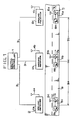
- a central service controller I and ground receivers 2 ... are connected to each other by means of circuit lines 3 ...
- the ground receivers 2a, 2b, 2c are equipped with antennas 4a, 4b, 4c respectively and are installed at fixed intervals along a road 9 which is a route where buses 5 ... run according to a basic schedule.
- the route buses 5a, 5b, 5c are running sequentially in the order of service
- mobile radio units 7a, 7b, 7c equipped with antennas 6a, 6b, 6c are installed in the buses 5a, 5b, 5c respectively together with service indicators 8a, 8b, 8c.
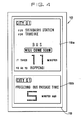
- each of the service indicators 8 has such a display panel 10 as shown in Fig. 2.
- individual indication contents are exhibited with, for example, a departure indicator lamp II showing characters for "departure” and a standby indicator lamp 12 showing characters for "standby".
- Each of such indicator lamps II, 12 intemally has a blink means such as a light emitting diode.
- the display panel 10 is attached at an easy-to-see position for a driver in the route bus. Meanwhile, the driver is ought to carry with him a service timetable 13 of Fig. 3 when leaving an office or the like to begin the daily route work.
- timetables 13 which are different from one another depending on a schedule number column 14 and a day-of-week column 15 even for the same route.
- a terminal name and stop names are shown in the uppermost row 16 ..., and the times of passage at such bus stops are written respectively in the lower rows 17.
- the illustrated service timetable 13 represents an exemplary schedule No. II for Saturday.
- This timetable 13 prescribes that the bus departing from the office at 12:11 reaches a first stop “Tarumi” at 12:19, then leaves there at 12:21 after a two-minute rest to pass via a stop “Sannomiya” and reaches a turn point "Okamoto" at 12:51, subsequently leaves there at 12:56 after a five-minute rest and, via "Sannomiya” at 13:08, reaches "Tarumi” at 13:24.
- the drivers on their duties with the above timetables 13 run the route buses 5a, 5b, 5c respectively according to the prescribed schedules with adjustment of the departure and arrival times of the buses in conformity to the instructions received from the service controlling system shown in Fig. I.
- the controller I estimates the time required for the specific route bus to pass through the sections where the ground receivers 2a -2c are installed. Such estimation is executed by various computations based on the past data in such a manner that, for example, the time to be required for the bus 5c to pass through the section 9a between the ground receivers 2a and 2b is computed by averaging the actually required passage times of the preceding buses 5a, 5b through the section 9a. In another example, the time to be required for the route bus 5b to pass through the section 9b is estimated on the basis of the time actually required for the preceding route bus 5a to pass through the section 9b. In accordance with such estimations, service instructions are outputted from the central service controller I to the individual route buses 5a -5c.
- the instructions are exhibited by turning on the corresponding indicator lamps II, 12 ... in the display panels 10 of the service indicators 8a -8c.
- the instructions from the central service controller I are transmitted to the service indicators 8b, 8c via the ground receivers 2b, 2a through the antennas 6b, 6c and the mobile radio units 7b, 7c in the route buses 5b, 5c.
- the central service controller I has a record of the mean time .needed for buses to cycle the complete service route and the average speed, and calculates the expected arrival time at the ground receiver 2b coming from the ground receiver 2a using the following equation.
- Expected arrival time (Passage time at ground receiver 2a) + (Distance between ground receivers 2a and 2b)/(Average speed in this route section) ; (I)
- the bus drivers carrying the service time tables as shown in Fig. 3 actually run the buses by receiving the service instructions on the display panel shown in Fig. 2 so that the buses are operated at a constant interval in consideration of the traffic congestion in each route section 9a, 9b and so on of the road 9.
- the road unit 18 is associated with the ground receiver 2 shown in Fig. I, and it is made up of a box accommodating the ground receiver 2 and the display panel 19 attached on the front of the box.
- the display panel 19 consists of an approach message section 19a and an service interval message section 19b.
- the road unit at the bus stop with the ground receiver 2b has its display panel 19 indicating "BUS WILL ARRIVE SOON" in the approach message section 19a in response to the detection of passage of the bus 5c at the former ground receiver 2a and also indicating the expected time needed for the coming bus to go to the next bus stop, e.g., ground receiver 2c.
- the road unit also has its display panel 19 digital indicating the lapse of time since the preceding bus 5b has passed by the ground receiver 2b in the service interval message section 19b.
- the foregoing route bus service controlling system has the following problems.
- the first problem is that in calculating the lapse of time taken by a bus for running through a unit segment such as between ground receivers 2a and 2b using the statistical average speed for the entire cycle of route, the expected lapse of time calculated as - (Distance between ground receivers 2a and 2b)-/(Statistical average speed in this section) is not always equal to the actual lapse of time estimated as (Distance between ground receivers 2a and 2b)-/(Running speed in this section) in the occurrence of traffice congestion or traffice accident.
- the service instruction using the lamps II and 12 on the display panel 10 of the operation instruction unit 8 as shown in Fig. 2 does not tell the bus driver of on what service diagram the bus should be run.
- the bus driver is required to make up an approximate service plan basing on the timetable 13 shown in Fig. 3 and in consideration of a delay at that time point, which sometimes exerts the driver to make a full- speed ride once the departure lamp II has lighted, in order to catch up the schedule.
- the conventional service instruction has been not only unkind to the bus drivers, but it has comprehended the matter of security in the traffic system inclusive of the passengers and other vehicles.
- a first object of the present invention is to provide a route bus operation controlling system in which the scheduled running time for certain route sections of the entire route and the actual running time are memorized in the central operation processor and the running time for the unit section is inferred and displayed basing on these values using the inference equations so that the error of the service message or service instruction from the actual running time for the unit section is prevented.
- a second object of the present invention is to provide a route bus service controlling system in which the running time for the unit section is inferred and displayed basing on the scheduled running time and actual running time of the unit section using the inference equations, instead of using the inference equations based on the average speed in the entire route, thereby enhancing the accuracy of inference and also extending the application of the inference equation to other sections.
- a third object of the present invention is to provide a route bus service controlling system in which the expected arrival time or expected running time of bus service is displayed on the display panel installed at each bus stop so as to provide a kind service information for the users.
- a fourth object of the present invention is to provide a route bus service controlling system in which the expected running time to the next bus stop or a certain position on the route is displayed for the bus driver or other staff so that the bus driver can run the bus easily, and at the same time an accurate running time in each section of route is informed to the passenger.
- the inventive route bus operation control system includes the aforementioned mobile radios, ground receivers and central service processor, wherein the central service processor is provided with a memory which stores the actual running time spent in passing through a unit section of a service route and other service information and a processing unit which reads out various service information in the memory to calculate factor data useful for the comparison of delay on each bus route, apply weight to the calculated data basing on the old and new actual values, calculate the average movement value of the running bus in the specific section as a sample value, and accumulate the expected running time of each specific section, and wherein the mobile radios and ground receivers and provided with display units for displaying service information pertinent to the specific section and the entire route.
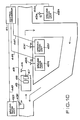
- reference number 21 denotes a central processor
- 22a, 22b and 22c are ground radio units installed at locations A, B and C, respectively
- 23a, 23b and 23c are antennas of the ground radio units 22a, 22b and 22c
- 24a, 24b and 24c are lines for connecting the ground radio units 22a, 22b and 22c to the central processor 21
- 25a, 25b and 25c are route buses
- 26a, 26b and 26c are mobile radio units installed on the buses 25a, 25b and 25c, respectively
- 27a, 27b and 27c are antennas of the mobile radio units 26a, 26b and 26c, respectively
- 28 indicates the running direction of the buses 25a, 25b and 25c
- 29 is the running route of the buses 25a, 25b and 25c.
- Fig. 6 shows the arrangement of the central processor 21.
- the central processor 21 consists mainly of a processing unit 30 such as a microprocessor, and it controls reading and writing of data to the memories 31 -39 performs computation for data stored in the memories 31 -39 and stores the result in the memories.
- a processing unit 30 such as a microprocessor
- 31 is a basic information memory provided for each lo- catiotrand route, and it stores the vehicle number, passage time and service diagram number.
- 32 is a standard running time memory provided for each location and route
- 33 is a passage information memory for storing the vehicle number of the passing bus, passage time and service diagram number
- 34 is an actual running time memory provided for each location and route
- 35 is an actual service interval memory provided for each route
- 36 is a memory for storing the delay factor normalized for the standard running time
- 37 is a memory for storing the weight applied to the actual value
- 38 is a sample value memory for storing the average movement value (sample value) of the running vehicle in the unit segment of a route
- 39 is a parameter memory for storing the parameters used in the weight calculation and sample value calculation.
- Reference number 40 denotes a display output unit which receives the vehicle number, route diagram number and arrival or departure time from the processor 30 and drives the display unit for the service manager (not shown) and the display unit installed in the terminal station and major bus stops (not shown).
- the mobile radio units 26a, 26b and 26c are installed on the buses 25a, 25b and 25c, respectively, the ground radio units. 22a, 22b and 22c making communication with the mobile radio units 26a, 26b and 26c are disposed on the route 29, and the central processor 21 is installed in the office.
- the central processor 21 collects the bus passage information from the ground radio units 22a, 22b and 22c over the lines 24a, 24b and 24c, and the information is processed by the processing unit 30 and stored in the passage information memory 33.
- the passage information (for each vehicle number, for each location and for each service diagram number) for each bus passing the locations A, B and C is stored in the passage information memory 33 while being collated with the contents of the service plan basic information memory 31. Among data accumulated in the passage information memory 33, only neces- . sary data is read out for computation by the processor 30, and the result is stored in the actual running time memory 34.
- the system determines the arrival time of the bus at the location B in the following way. For the inference calculation of the running time between locations A and B, relatively new actual value made by previous bus (25b, 25c, ..., or 25n) which has passed the location B is used after modification. The calculation is implemented using "delay factor”, "weight” and "average movement value, i.e., sample value”, all defined in the following.
- the standard running time of route buses between locations is scheduled in advance and it varies depending on the hour and route.
- the actual running time of a bus between locations A and B also varies depending on the hour and route, and therefore a value compared with some reference value need to be used.
- the reference running time is defined as delay factors Di as follows. where ri is actual running time and Ts is the standard running time.
- the previous buses 25b, 25c and so on have their actual running time r0, r-I and r-2, respectively, and these values are read out from the actual running time memory 34 as shown in Fig. 6, and the standard running time Ts is read out from the standard running time memory 32.
- the conventional system has simply used the mean value of the actual running time in the past.
- the actual running time in the past is used by setting a finite time frame.
- the bus service is different in the interval of service depending on each route and segment. For example, buses may run at an interval of three minutes or at an interval of 30 minutes, and this causes different number of samples of the actual data used. Accordingly, actual data must be used to meet the features of each route and section.
- the road traffics vary time to time, and the use of too old actual data may not match the current situation.
- the latest actual data best reflects the traffic situation of that time point, and this invention confines the time frame and applies weight to the actual data in extracting the actual data.
- the weight is larger for a newer actual value and smaller for an older actual value.
- s0 and s-I are the arrival time of the preceding buses 25b and 25c at location A in Fig. 5, and a and b are parameters.
- the weight of each preceding bus is calculated using Equation - (4), and the resultant weights are stored in the weight memory 37.
- the actual running time between locations A and B will fluctuate even in the same hour of day depending on the number of passengers, waiting for signals and other traffic conditions, and in this invention the inference calculation for the arrival time uses the average movement value (will be termed "sample value" hereinafter) for the preceding buses.
- weights are read out of the weight memory 37, delay coefficient are read out of the delay coefficient memory 36, and the processor 30 calculates the Equations (5) and (6), and the results are stored in the sample memory 38.
- the forecasting calculation for the arrival time of the bus under inference at the location B is carried out using the sample values of the preceding buses and the sample value lI (forecasting value) of the bus under forecasting derived from the passage time of the preceding buses at the location A.
- Fig. 7 is a graph showing the relation between the sample values and section entry time which is the passage time of the bus under forecast at the location A in Fig. 5.
- the section entry time of the bus under inference and preceding buses is plotted on the horizontal axis against the sample values of these buses on the vertical axis. From Fig. 7, the sample value 11 of the bus under forecast is given as follows. namely, where kl is the gradient of the line.
- kl is the gradient of the line, it is approximated by the gradient of a quadratic curve for simplification of calculation, as follows.
- c is the upper limit of forecast.
- the running time (forecast value) of the bus 25a between the locations A and B is equal to the sample value 11 multiplied by the standard running time Ts between A and B, i.e., 11 x Ts. Accordingly, the passage time of the bus 25a at the location B is equal to the passage time at location A plus the running time between A and B as,
- the passage time of the bus 25a at the location B is forecasted as follows.
- the sample values of the preceding buses shown in Fig. 6 are read out of the sample memory 38
- the passage time of the bus 25a and preceding buses at the location A is read out of the passage information memory 33
- the parameter c is read out of the parameter memory 39
- Equations (7), (8) and (9) are calculated by the processor 30
- the sample value 11 of the bus 25a is stored in the sample memory 38
- Equation (10) is calculated by the processor 30.
- the passage time of the bus 25a at the location C is obtained by cumulating the forecasted running time for the specified sections between A and B and between B and C.
- the passage time for locations farther than the location C can be calculated by cumulating the expected running time of each specified section using the actual values experienced by the preceding buses.
- the result of process for the expected passage time of the bus under inference by the processor 30 shown in Fig. 6 is read out of the service plan basic information memory 31 and displayed together with the actual values retrieved from the passage information memory 33 on the display unit 40, and the scheduled passage time at each location on the route of the buses 25a -25c and their actual values can be displayed.
- This allows tracing control for the service of each bus, which is displayed on the CRT screen in the office, and the expected departure time and arrival time can be displayed on the display units installed at bus stops on the route through the lines 24a, 24b and 24c from the central processing unit 21.
- Fig. 8 shows the principle of calculating the service interval of buses according to the second embodiment of this invention.
- the vertical axis represents time (in minutes), the upper half being the actual number of buses which have passed in the past in front of the guidance display unit, while the lower half being the expected number of buses which will pass in front of the guidance display unit.
- the position of the approach guidance display unit is conceived to be a 0 minute position on the horizontal axis. For example, the following is the case of buses passing the location A.
- B-I, B-2, ..., B-n are buses which have passed in front of the approach message display unit in the past 15 minutes
- BI, B2, ..., Bm are buses which will pass in front of the approach guidance display unit in the coming 15 minutes.
- the central processing unit 21 collects the passage information of buses which pass in front of the ground radio units 22a, 22b and 22c by the poling signal having a certain frequency, and therefor by transmitting the service interval data calculated using the Equation (3) to the ground radio units 22a, 22b and 22c via the lines 24a, 24b and 24c at a certain time interval (e.g., one minute), the service interval displayed on the approach guidance display unit (will be described later) is updated continuously and the service interval which best reflects the traffic situation is displayed.
- a certain time interval e.g., one minute
- Fig. 9 for the third embodiment of this invention, identical components to those shown in Fig. 5 are referred to by the common symbols.
- Fig. 10 shows the device disposition at the terminal station and in the vicinity of the terminal station according to the fourth embodiment of this invention.
- reference number 41 denotes the central processing unit
- 42P-42S are ground radio units
- 46 is a route bus
- 47 is a mobile radio unit
- 48 is an service instruction unit
- 48P-48S are antennas
- 44P-44S are lines
- 46 is a mobile antenna
- 49 is a running route
- P, Q, R and S are ground radio unit installation points
- the arrow indicates the bus running direction.
- Fig. II shows the service instruction unit 28 equipped on the route bus according to the fifth embodiment of this invention.
- the display unit 50 consists of an incoming information display section 51, an service time display section 52 and other information display section 53.
- Figs. 12 through 15 show the modified versions of the display unit installed at bus stops according to the sixth through ninth embodiments of this invention in which like symbols indicate like components throughout the figures.
- a ground radio unit 61 is accommodated inside the road unit 60, and a display unit 62 is placed below the ground radio unit 61.
- the display unit 62 is used for a bus stop where only one service route is placed, and its display panel 63 has a print of invariable information such as the destination of bus, and it also has a digital display panel 64 at the central section thereof on which operational information based on the computation by the central processing unit 21 or 41, as has been described in the previous first through fourth embodiments, is displayed by means of liquid crystal or light emitting diode devices.
- the display unit 62 which displays the service time derived from the actual values and expected values processed by the central processor 21 or 41, as described in the previous first through fourth embodiments, has its display panel 63 provided with a departure time display section 65 for a bus which has arrived at that bus stop earlier and will depart first and a departure time display section 66 for a bus which will depart later.
- a display unit 62 is installed at a bus stop where two routes of bus service are placed, and the upper part of the display panel 63 is provided with a first display section 67 for displaying the arrival or departure time of the earliest bus among route buses destining for A, and the lower part is provided with a second display section 68 for displaying the arrival or departure time of a bus destining for B.
- the ninth embodiment shown in Fig. 15 is a modified version of the eighth embodiment shown in Fig. 14, and reference numbers 60 -63, 67 and 68 are the same in both embodiments.
- a first indicator lamp 70 having a label of "ABOUT”
- a second indicator lamp 80 similar to 67 is provided in the vicinity of the second display section 68.
- These lamps 70 and 80 light up when the expected arrival or departure time of a bus for location A transmitted from the central operation processor 21 or 41 varies time to time, indicating that the time displayed in the section 67 or 68 is still uncertain.
- information displayed on the display unit at the bus stop of location S in the fourth embodiment is uncertain until the bus 45 from location P has passed location Q, but after the passage of location R the accuracy of information will be significantly high, and therefore the indicator lamp 70 or 80 is turned off after the bus has passed the location R so that the user is made known that time information displayed in the display section 67 or 68 is relatively reliable.
- the inventive route bus service controlling system provides the following effectiveness.
- the running time in a specific section of a bus service route is expected using equations basing on the scheduled running time and actual data obtained by several buses which have run in the past and the forecasted running time is displayed on the display unit, which prevents an error of the service guidance message and service instruction information from the actual running time, whereby the reliability of the service instruction and guidance information for the bus driver and passenger can be improved significantly.
- the forecast calculation for service information is based on the scheduled running time in a specific section of the overall route and the actual data obtained by buses which have run the section, which allows the enhanced accuracy of forecast and application to other sections, whereby versatility and usefulness can be improved significantly.
- the expected arrival time or expected running time between the bus stop of the route bus is displayed accurately on the display panel of the road unit installed at the bus stop, which provides accurate service guidance information for the user, whereby the usefulness for the route bus user can be improved.
- an accurate expected running time or arrival time at the next bus stop or specific location is displayed on the display unit installed on the vehicle, which provides accurate service information for the bus driver and passenger, whereby the usefulness can be improved also in this respect.
Abstract
Description
- The present invention relates to a system for controlling a route bus service by first collecting information at passage points of buses running on a regular route according to a basic schedule, then estimating the time of arrival of each running bus at a terminal, subsequently modifying the basic - schedule so as to enable the route buses to depart from the terminal sequentially at equal time intervals, and displaying service information such as a timetable and so forth on a service indicator installed in each bus.
- In the current urban traffic where automobiles occupy a major position, there exist some serious urban problems including traffic congestion and so forth that result from overpopulated city structure, and it is of great importance to secure, in the highly dense urban road network, smooth service of transportation means such as route buses which are operated principally for the public.
- Similarly in medium-and long-distance transportation means which serve for communication between cities, there may occur troubles that normal service conforming a basic schedules fails to be achieved due to road construction or traffic accidents on regular routes.
- In view of such circumstances mentioned above, one prior invention titled "Method for control of specific automobile service" is known as disclosed in Japanese Patent Publication No. 54-11878 (published on May 18 1979).
- Figs. I through 3 illustrate a conventional apparatus designed for controlling the service of specific automobiles such as route buses. In Fig. I, a central service controller I and
ground receivers 2 ... are connected to each other by means ofcircuit lines 3 ... Theground receivers antennas 4a, 4b, 4c respectively and are installed at fixed intervals along aroad 9 which is a route wherebuses 5 ... run according to a basic schedule. In this example theroute buses antennas 6a, 6b, 6c are installed in thebuses service indicators 8a, 8b, 8c. - In the system having the above-mentioned constitution for controlling the operation of automobiles such as route buses, each of the service indicators 8 has such a
display panel 10 as shown in Fig. 2. On the obverse side of thedisplay panel 10, individual indication contents are exhibited with, for example, a departure indicator lamp II showing characters for "departure" and astandby indicator lamp 12 showing characters for "standby". Each of such indicator lamps II, 12 intemally has a blink means such as a light emitting diode. Thedisplay panel 10 is attached at an easy-to-see position for a driver in the route bus. Meanwhile, the driver is ought to carry with him aservice timetable 13 of Fig. 3 when leaving an office or the like to begin the daily route work. There are prepared several kinds ofsuch timetables 13 which are different from one another depending on aschedule number column 14 and a day-of-week column 15 even for the same route. In the contents described on thetimetable 13, a terminal name and stop names are shown in theuppermost row 16 ..., and the times of passage at such bus stops are written respectively in thelower rows 17. The illustratedservice timetable 13 represents an exemplary schedule No. II for Saturday. Thistimetable 13 prescribes that the bus departing from the office at 12:11 reaches a first stop "Tarumi" at 12:19, then leaves there at 12:21 after a two-minute rest to pass via a stop "Sannomiya" and reaches a turn point "Okamoto" at 12:51, subsequently leaves there at 12:56 after a five-minute rest and, via "Sannomiya" at 13:08, reaches "Tarumi" at 13:24. Ten minutes later, the bus departs from "Tarumi" again at 13:34 and thereafter the service is kept according to the timetable. - The drivers on their duties with the
above timetables 13 run theroute buses - Now the operation of the above service controlling system will be described below with reference to Fig. I. First the radio waves transmitted from the running
buses 5a -5c are caught by the antenna 4a -4c of theground receivers 2a -2c installed at predetermined points on theroad 9 of a service route. The waves from thebuses 5a -5c are transmitted by the mobile radio units 7a -7c through the antennas 6a -6c at fixed frequencies selected with respect to the individual buses. Therefore the intervals between theroute buses 5 running in the order of 5a, 5b, 5c are caught in the form of radio waves by theground receivers 2a -2c, whose outputs are transmitted via thecircuit lines 3 ... to the central service controller I. Then the controller I estimates the time required for the specific route bus to pass through the sections where theground receivers 2a -2c are installed. Such estimation is executed by various computations based on the past data in such a manner that, for example, the time to be required for thebus 5c to pass through the section 9a between theground receivers buses route bus 5b to pass through the section 9b is estimated on the basis of the time actually required for the precedingroute bus 5a to pass through the section 9b. In accordance with such estimations, service instructions are outputted from the central service controller I to theindividual route buses 5a -5c. The instructions are exhibited by turning on the corresponding indicator lamps II, 12 ... in thedisplay panels 10 of the service indicators 8a -8c. For example, when theroute buses ground receivers service indicators 8b, 8c via theground receivers antennas 6b, 6c and the mobile radio units 7b, 7c in theroute buses - The central service controller I has a record of the mean time .needed for buses to cycle the complete service route and the average speed, and calculates the expected arrival time at the
ground receiver 2b coming from theground receiver 2a using the following equation. - Expected arrival time = (Passage time at
ground receiver 2a) + (Distance betweenground receivers - Accordingly, the bus drivers carrying the service time tables as shown in Fig. 3 actually run the buses by receiving the service instructions on the display panel shown in Fig. 2 so that the buses are operated at a constant interval in consideration of the traffic congestion in each route section 9a, 9b and so on of the
road 9. - At each bus stop, users of bus have service information displayed on a
display panel 19 provided on aroad unit 18, as shown in Fig. 4, to know the situation of bus service on the route and expected time needed to go to the next bus stop. Theroad unit 18 is associated with theground receiver 2 shown in Fig. I, and it is made up of a box accommodating theground receiver 2 and thedisplay panel 19 attached on the front of the box. Thedisplay panel 19 consists of anapproach message section 19a and an serviceinterval message section 19b. For example, the road unit at the bus stop with theground receiver 2b has itsdisplay panel 19 indicating "BUS WILL ARRIVE SOON" in theapproach message section 19a in response to the detection of passage of thebus 5c at theformer ground receiver 2a and also indicating the expected time needed for the coming bus to go to the next bus stop, e.g.,ground receiver 2c. The road unit also has itsdisplay panel 19 digital indicating the lapse of time since the precedingbus 5b has passed by theground receiver 2b in the serviceinterval message section 19b. - The foregoing route bus service controlling system, however, has the following problems. The first problem is that in calculating the lapse of time taken by a bus for running through a unit segment such as between
ground receivers ground receivers ground receivers - (Distance between
ground receivers ground receivers - Such a situation causes a significant difference between the service information calculated by the central service controller I and displayed on the route unit at each bus stop and the actual result, resulting in a degraded dependability on the displayed service information for the users and bus drivers.
- In connection with the above problem, it was unclear in determining up to what time point passage data should be traced back for evaluating the statistical average speed in each route section. Because of different traffic conditions of route sections such as the degree of traffic congestion and the distance of route section, it is not possible to provide accurate service information for the bus drivers, passengers and users waiting at each bus stop through the inference based simply on the Equation (1).
- Among displayed information on the
display panel 19 of theroad unit 18 at each bus stop, as shown in Fig. 4, information in theapproach message section 19a is particularly lacking in accuracy. Namely, when a user waits for a bus at a bus stop with a road unit 18n having an associated display panel 19n and a bus is passing by the previous road unit 18n-1, the user watches the road unit 18n to read in theapproach message section 19a "BUS WILL ARRIVE SOON", but the expression "SOON" is ambiguous because the wait time depends on the traffic condition between the road units 18n-1 and 18n. This means that the user does not know clearly whether the intended bus will come one minute, three minutes or five minutes later, and the user is unkindly be compelled to infer the arrival time of the coming bus using information such as the lapse of time since the last bus has gone and time taken to go to the next bus stop displayed on the serviceinterval message section 19b and the service timetable posted at the bus stop. - Moreover, the service instruction using the lamps II and 12 on the
display panel 10 of the operation instruction unit 8 as shown in Fig. 2 does not tell the bus driver of on what service diagram the bus should be run. On this account, the bus driver is required to make up an approximate service plan basing on thetimetable 13 shown in Fig. 3 and in consideration of a delay at that time point, which sometimes exerts the driver to make a full- speed ride once the departure lamp II has lighted, in order to catch up the schedule. The conventional service instruction has been not only unkind to the bus drivers, but it has comprehended the matter of security in the traffic system inclusive of the passengers and other vehicles. - A first object of the present invention is to provide a route bus operation controlling system in which the scheduled running time for certain route sections of the entire route and the actual running time are memorized in the central operation processor and the running time for the unit section is inferred and displayed basing on these values using the inference equations so that the error of the service message or service instruction from the actual running time for the unit section is prevented. A second object of the present invention is to provide a route bus service controlling system in which the running time for the unit section is inferred and displayed basing on the scheduled running time and actual running time of the unit section using the inference equations, instead of using the inference equations based on the average speed in the entire route, thereby enhancing the accuracy of inference and also extending the application of the inference equation to other sections.
- A third object of the present invention is to provide a route bus service controlling system in which the expected arrival time or expected running time of bus service is displayed on the display panel installed at each bus stop so as to provide a kind service information for the users.
- A fourth object of the present invention is to provide a route bus service controlling system in which the expected running time to the next bus stop or a certain position on the route is displayed for the bus driver or other staff so that the bus driver can run the bus easily, and at the same time an accurate running time in each section of route is informed to the passenger.
- In order to achieve the above objectives, the inventive route bus operation control system includes the aforementioned mobile radios, ground receivers and central service processor, wherein the central service processor is provided with a memory which stores the actual running time spent in passing through a unit section of a service route and other service information and a processing unit which reads out various service information in the memory to calculate factor data useful for the comparison of delay on each bus route, apply weight to the calculated data basing on the old and new actual values, calculate the average movement value of the running bus in the specific section as a sample value, and accumulate the expected running time of each specific section, and wherein the mobile radios and ground receivers and provided with display units for displaying service information pertinent to the specific section and the entire route.
-
- Fig. I is a block diagram showing the overall arrangement of the conventional route bus service control system;
- Fig. 2 is a front view of the service instruction unit installed on the vehicle;
- Fig. 3 is a diagram showing the service timetable carried by the bus driver during the service to which the control system of Fig. I is applied;
- Fig. 4 is a front view of the user message display unit installed at each bus stop in the conventional service controlling system shown in Fig. I;
- Fig. 5 is a block diagram showing the overall arrangement of the route bus service controlling system which is the first embodiment of this invention;
- Fig. 6 is a block diagram showing the arrangement of the central service processor of the first embodiment;
- Fig. 7 is a diagram showing the principle of calculating the expected running time according to the first embodiment;
- Fig. 8 is a diagram showing the principle of calculating the route bus service interval time according to the second embodiment of this invention;
- Fig. 9 is a block diagram used to explain the overall arrangement of the third embodiment of the invention used for the operation control in the neighborhood of the terminal station;
- Fig. 10 is a diagram showing the disposition of devices in the neighborhood of the terminal station according to the fourth embodiment of the invention;
- Fig. II is a front view of the display unit installed in the bus according to the fifth embodiment of this invention; and
- Figs. 12 through 15 are diagrams each showing the front view of the user guidance display unit installed at each bus stop according to the sixth through ninth embodiments of this invention.
- Several preferred embodiment of this invention will be described with reference to the drawings.
- The first embodiment will be described using Figs. 5, 6 and 7. In Fig. 5,
reference number 21 denotes a central processor; 22a, 22b and 22c are ground radio units installed at locations A, B and C, respectively; 23a, 23b and 23c are antennas of theground radio units ground radio units central processor 21; 25a, 25b and 25c are route buses; 26a, 26b and 26c are mobile radio units installed on thebuses mobile radio units buses buses - Fig. 6 shows the arrangement of the
central processor 21. Thecentral processor 21 consists mainly of aprocessing unit 30 such as a microprocessor, and it controls reading and writing of data to the memories 31 -39 performs computation for data stored in the memories 31 -39 and stores the result in the memories. Among the memories, 31 is a basic information memory provided for each lo- catiotrand route, and it stores the vehicle number, passage time and service diagram number. 32 is a standard running time memory provided for each location and route, 33 is a passage information memory for storing the vehicle number of the passing bus, passage time and service diagram number, 34 is an actual running time memory provided for each location and route, 35 is an actual service interval memory provided for each route, 36 is a memory for storing the delay factor normalized for the standard running time, 37 is a memory for storing the weight applied to the actual value, 38 is a sample value memory for storing the average movement value (sample value) of the running vehicle in the unit segment of a route, and 39 is a parameter memory for storing the parameters used in the weight calculation and sample value calculation.Reference number 40 denotes a display output unit which receives the vehicle number, route diagram number and arrival or departure time from theprocessor 30 and drives the display unit for the service manager (not shown) and the display unit installed in the terminal station and major bus stops (not shown). - Next, the operation will be described. The
mobile radio units buses mobile radio units route 29, and thecentral processor 21 is installed in the office. Thecentral processor 21 collects the bus passage information from theground radio units lines processing unit 30 and stored in thepassage information memory 33. The passage information (for each vehicle number, for each location and for each service diagram number) for each bus passing the locations A, B and C is stored in thepassage information memory 33 while being collated with the contents of the service planbasic information memory 31. Among data accumulated in thepassage information memory 33, only neces- . sary data is read out for computation by theprocessor 30, and the result is stored in the actualrunning time memory 34. - After the
bus 25a has passed the location A, the system determines the arrival time of the bus at the location B in the following way. For the inference calculation of the running time between locations A and B, relatively new actual value made by previous bus (25b, 25c, ..., or 25n) which has passed the location B is used after modification. The calculation is implemented using "delay factor", "weight" and "average movement value, i.e., sample value", all defined in the following. - Generally, the standard running time of route buses between locations is scheduled in advance and it varies depending on the hour and route. The actual running time of a bus between locations A and B also varies depending on the hour and route, and therefore a value compared with some reference value need to be used. In this embodiment, the reference running time is defined as delay factors Di as follows.

- In Fig. 5, the
previous buses running time memory 34 as shown in Fig. 6, and the standard running time Ts is read out from the standardrunning time memory 32. Theprocessor 30 makes computation using these values to evaluate delay factors DO = r0/Ts, D-I = r-I/Ts and D-2 = r-2/Ts, and stores them in thedelay factor memory 36. - For the inference of the running time in each unit segment (between locations A and B and between B and C in Fig. 5), the conventional system has simply used the mean value of the actual running time in the past. In this invention, the actual running time in the past is used by setting a finite time frame. The bus service is different in the interval of service depending on each route and segment. For example, buses may run at an interval of three minutes or at an interval of 30 minutes, and this causes different number of samples of the actual data used. Accordingly, actual data must be used to meet the features of each route and section. The road traffics vary time to time, and the use of too old actual data may not match the current situation. The latest actual data best reflects the traffic situation of that time point, and this invention confines the time frame and applies weight to the actual data in extracting the actual data. The weight is larger for a newer actual value and smaller for an older actual value. The weight Wi is defined as a function of the service interval as follows.

where a is a weight compensating coefficient, b is an upper limit of service interval, and s is the arrival time of bus at location A. - s0 and s-I are the arrival time of the preceding
buses buses previous bus 25b has a weight of WO = I. When the service interval is short, the number of samples increase, causing the weight to disperse, while when the operation interval is long, the number of samples decreases, causing actual data of buses more immediate to the bus under inference to have larger weights. The weight of each preceding bus is calculated using Equation - (4), and the resultant weights are stored in theweight memory 37. The actual running time between locations A and B will fluctuate even in the same hour of day depending on the number of passengers, waiting for signals and other traffic conditions, and in this invention the inference calculation for the arrival time uses the average movement value (will be termed "sample value" hereinafter) for the preceding buses. - The following defines the sample values for the preceding
buses 
where 10 is the sample value ofprevious bus 25b, ℓ-I is the sample value of the precedingbus 25c, and 1-2 is the sample value of the further preceding bus (not shown), WO and W-I are weights for the previous and precedingbuses buses - For the sample values of the preceding buses, weights are read out of the
weight memory 37, delay coefficient are read out of thedelay coefficient memory 36, and theprocessor 30 calculates the Equations (5) and (6), and the results are stored in thesample memory 38. The forecasting calculation for the arrival time of the bus under inference at the location B is carried out using the sample values of the preceding buses and the sample value ℓI (forecasting value) of the bus under forecasting derived from the passage time of the preceding buses at the location A. - Fig. 7 is a graph showing the relation between the sample values and section entry time which is the passage time of the bus under forecast at the location A in Fig. 5. The section entry time of the bus under inference and preceding buses is plotted on the horizontal axis against the sample values of these buses on the vertical axis. From Fig. 7, the
sample value 11 of the bus under forecast is given as follows.

- Although kl is the gradient of the line, it is approximated by the gradient of a quadratic curve for simplification of calculation, as follows.


- The running time (forecast value) of the
bus 25a between the locations A and B is equal to thesample value 11 multiplied by the standard running time Ts between A and B, i.e., 11 x Ts. Accordingly, the passage time of thebus 25a at the location B is equal to the passage time at location A plus the running time between A and B as, - Passage time at location B = sl + 11 1 Ts..... (10)
- Accordingly, the passage time of the
bus 25a at the location B is forecasted as follows. The sample values of the preceding buses shown in Fig. 6 are read out of thesample memory 38, the passage time of thebus 25a and preceding buses at the location A is read out of thepassage information memory 33, the parameter c is read out of theparameter memory 39, Equations (7), (8) and (9) are calculated by theprocessor 30, thesample value 11 of thebus 25a is stored in thesample memory 38, and finally Equation (10) is calculated by theprocessor 30. In the same way, the passage time of thebus 25a at the location C is obtained by cumulating the forecasted running time for the specified sections between A and B and between B and C. - The passage time for locations farther than the location C can be calculated by cumulating the expected running time of each specified section using the actual values experienced by the preceding buses. The result of process for the expected passage time of the bus under inference by the
processor 30 shown in Fig. 6 is read out of the service planbasic information memory 31 and displayed together with the actual values retrieved from thepassage information memory 33 on thedisplay unit 40, and the scheduled passage time at each location on the route of thebuses 25a -25c and their actual values can be displayed. This allows tracing control for the service of each bus, which is displayed on the CRT screen in the office, and the expected departure time and arrival time can be displayed on the display units installed at bus stops on the route through thelines central processing unit 21. - Although in the above embodiment the sample value (expected value) of the bus under inference is calculated through the approximation of the gradient kl of the line for Equation (7) by the quadratic curve in the Equations (8) and (9), approximation with other function for simplifying the calculation will achieve the same effect as of the above embodiment.
- Although in the above first embodiment the computational process for obtaining the passage time of a bus at a specific location of the route has been described, it is also possible to calculate the service interval of buses through the inference of the number of buses passing at a certain location in a certain time length, as will be described in the following second embodiment.
- Fig. 8 shows the principle of calculating the service interval of buses according to the second embodiment of this invention. The vertical axis represents time (in minutes), the upper half being the actual number of buses which have passed in the past in front of the guidance display unit, while the lower half being the expected number of buses which will pass in front of the guidance display unit. The position of the approach guidance display unit is conceived to be a 0 minute position on the horizontal axis. For example, the following is the case of buses passing the location A. In the figure, B-I, B-2, ..., B-n are buses which have passed in front of the approach message display unit in the past 15 minutes, and BI, B2, ..., Bm are buses which will pass in front of the approach guidance display unit in the coming 15 minutes. When buses are in the positional relation as shown on the position vs. time coordinates in Fig. 8, the service interval t (minutes) of buses passing in front of the approach guidance display unit is expressed as follows.

- The
central processing unit 21 collects the passage information of buses which pass in front of theground radio units ground radio units lines - Although the above first and second embodiments have been described for the case of route bus service in a linear specific section of the route, this invention is also applicable to the specific section where buses turn back in the vicinity of the bus terminal which is the service reference point of the route bus, as will be described in the following third and fourth embodiments in connection with Figs. 9 and 10.
- In Fig. 9 for the third embodiment of this invention, identical components to those shown in Fig. 5 are referred to by the common symbols. When a bus has passed the arrival forecast point P in the vicinity of the bus terminal station, communication is made between the
ground radio unit 22P and themobile radio unit 27 on thebus 25 via the antenna 23P on the ground and theantenna 26 on the vehicle, so that the bus passage information is sent via the line 24p to thecentral processing unit 21 and the arrival time of the bus at the terminal station is expected using the above forecast equations. - Fig. 10 shows the device disposition at the terminal station and in the vicinity of the terminal station according to the fourth embodiment of this invention. In the figure,
reference number 41 denotes the central processing unit, 42P-42S are ground radio units, 46 is a route bus, 47 is a mobile radio unit, 48 is an service instruction unit, 48P-48S are antennas, 44P-44S are lines, 46 is a mobile antenna, 49 is a running route, P, Q, R and S are ground radio unit installation points, and the arrow indicates the bus running direction. - Fig. II shows the
service instruction unit 28 equipped on the route bus according to the fifth embodiment of this invention. In the figure, thedisplay unit 50 consists of an incominginformation display section 51, an servicetime display section 52 and otherinformation display section 53. - Figs. 12 through 15 show the modified versions of the display unit installed at bus stops according to the sixth through ninth embodiments of this invention in which like symbols indicate like components throughout the figures.
- In the sixth embodiment shown in Fig. 12, a
ground radio unit 61 is accommodated inside theroad unit 60, and adisplay unit 62 is placed below theground radio unit 61. In this embodiment, thedisplay unit 62 is used for a bus stop where only one service route is placed, and itsdisplay panel 63 has a print of invariable information such as the destination of bus, and it also has adigital display panel 64 at the central section thereof on which operational information based on the computation by thecentral processing unit - In the seventh embodiment shown in Fig. 13, the
display unit 62, which displays the service time derived from the actual values and expected values processed by thecentral processor display panel 63 provided with a departuretime display section 65 for a bus which has arrived at that bus stop earlier and will depart first and a departuretime display section 66 for a bus which will depart later. - In the eighth embodiment shown in Fig. 14, a
display unit 62 is installed at a bus stop where two routes of bus service are placed, and the upper part of thedisplay panel 63 is provided with afirst display section 67 for displaying the arrival or departure time of the earliest bus among route buses destining for A, and the lower part is provided with asecond display section 68 for displaying the arrival or departure time of a bus destining for B. - Finally, the ninth embodiment shown in Fig. 15 is a modified version of the eighth embodiment shown in Fig. 14, and reference numbers 60 -63, 67 and 68 are the same in both embodiments. In the vicinity of the
first display section 67, there is provided afirst indicator lamp 70 having a label of "ABOUT", and asecond indicator lamp 80 similar to 67 is provided in the vicinity of thesecond display section 68. Theselamps central operation processor section bus 45 from location P has passed location Q, but after the passage of location R the accuracy of information will be significantly high, and therefore theindicator lamp display section - As described above in detail, the inventive route bus service controlling system provides the following effectiveness.
- Firstly, the running time in a specific section of a bus service route is expected using equations basing on the scheduled running time and actual data obtained by several buses which have run in the past and the forecasted running time is displayed on the display unit, which prevents an error of the service guidance message and service instruction information from the actual running time, whereby the reliability of the service instruction and guidance information for the bus driver and passenger can be improved significantly.
- Secondly, the forecast calculation for service information is based on the scheduled running time in a specific section of the overall route and the actual data obtained by buses which have run the section, which allows the enhanced accuracy of forecast and application to other sections, whereby versatility and usefulness can be improved significantly.
- Thirdly, the expected arrival time or expected running time between the bus stop of the route bus is displayed accurately on the display panel of the road unit installed at the bus stop, which provides accurate service guidance information for the user, whereby the usefulness for the route bus user can be improved.
- Finally, as the fourth effect, an accurate expected running time or arrival time at the next bus stop or specific location is displayed on the display unit installed on the vehicle, which provides accurate service information for the bus driver and passenger, whereby the usefulness can be improved also in this respect.
Claims (6)
- I. A route bus service controlling system including a mobile radio unit equipped on a route bus, ground radio units installed at a certain interval of distance along the entire route of the bus, a central processor which calculates expected operational information for a specific section of said route basing on passage information provided by said mobile radio unit and ground radio units, and a display unit for displaying said expected service information, wherein said central processor comprises:a memory for storing service plan basic information, passage information, actual running time in said section, standard running time, and actual service interval; anda processing unit which adds a passage time of a bus under forecast at the arrival at a latest ground radio unit to a sum of expected running time for divided unit segments of route where the bus does not yet run, limits a time frame of running time of buses which have run in the past used for the forecast process, calculates an average movement value of a plurality of buses which have passed in said specific section before the bus under forecast by using a delay coefficient normalized by the standard running time for the actual running time and a weight value for the actual running time, limits an entry time of said bus under forecast and buses which have run into each specified section, limits the time frame of forecast, expects a sample value of each specified section for the bus under forecast from the calculated average movement value, calculates an expected running time in each specified section by multiplying said expected sample value to said standard running time, and calculates arrival time at a specific location by cumulating expected running time of each specified section in a portion of route where the bus does not yet run through the similar computational process, and wherein display means for displaying arrival time at a specific location and tracing control information of route bus operation calculated by said processor is provided in each location of the bus route and on the route bus.
- 2. A system according to claim I, wherein said central processor comprises a processing unit which calculates the bus service interval at a certain time interval, based on an actual number of buses which have passed in a certain time length in the past in front of a road unit incorporating the ground radio unit installed at each location of the bus route and an expected number of buses which will pass in a certain time length in the future, from a sum of the actual number of buses and the expected number of buses and from a sum of each certain time length, and wherein an approach guidance display unit for displaying the result of calculation is incorporated in said road unit.
- 3. A system according to claim I, wherein said central processor comprises a processing unit which limits the time frame of running time in the past (actual value) used for the inference process, calculates average movement values ti (will be termed sample values) of buses which have passed the specified section of route before the bus under forecast by using a delay coefficient D normalized by a standard running time for an actual running time and a weight value W for the actual running time as:


- 4. A system according to claim I, wherein said central processor comprises
A-A'
, and wherein said display means is provided in a road unit on the bus route incorporating said ground radio unit so as to constitute an approach guidance display unit for displaying the arrival time or departure time of the route bus. - 5. A system according to claim I, wherein said display means is provided in a road unit on the bus route incorporating said ground radio unit so as to constitute an approach guidance display unit for displaying the arrival time or departure time of the route bus.
- 6. A system according to claim I, wherein said central processor comprise
A-A'
, and wherein a road unit is installed at each of an expected arrival location in the vicinity of a bus terminal, a final arrival location immediately before the bus terminal, an incoming instruction information reception location and a bus stop in the bus terminal, said central processor operating to expect the arrival time of a bus at the bus terminal when the bus has arrived at the expected arrival location, produce a service time table for the next cycle of service (from the bus terminal to a turning point and back to the terminal), fix the service time table for one cycle of service when the bus has arrived at the final arrival location immediately before the bus terminal basing on the actual running time experienced in this service, produce service instruction information (incoming instruction information for moving the bus to the bus stop in the terminal in the next service, service time table and other information), transmit the incoming instruction information to a road post at a reception location for the information and other information to a road post at the bus stop in the terminal, and display the service instruction information on the service instruction unit on the vehicle through communication with the road unit during the entry of the bus to the terminal.
Applications Claiming Priority (12)
| Application Number | Priority Date | Filing Date | Title |
|---|---|---|---|
| JP23905685A JPS6299899A (en) | 1985-10-25 | 1985-10-25 | Line bus operation managing apparatus |
| JP239058/85 | 1985-10-25 | ||
| JP23905885A JPS6299900A (en) | 1985-10-25 | 1985-10-25 | Line bus operation managing apparatus |
| JP239056/85 | 1985-10-25 | ||
| JP24454585A JPS62102397A (en) | 1985-10-29 | 1985-10-29 | Line bus operation managing apparatus |
| JP244544/85 | 1985-10-29 | ||
| JP244545/85 | 1985-10-29 | ||
| JP60244544A JPS62102396A (en) | 1985-10-29 | 1985-10-29 | Line bus operation managing apparatus |
| JP249611/85 | 1985-11-06 | ||
| JP24961185A JPS62108399A (en) | 1985-11-06 | 1985-11-06 | Line bus operation managing apparatus |
| JP62054/86 | 1986-03-18 | ||
| JP6205486A JPS62217400A (en) | 1986-03-18 | 1986-03-18 | Line bus operation managing apparatus |
Publications (3)
| Publication Number | Publication Date |
|---|---|
| EP0219859A2 true EP0219859A2 (en) | 1987-04-29 |
| EP0219859A3 EP0219859A3 (en) | 1988-11-23 |
| EP0219859B1 EP0219859B1 (en) | 1993-10-06 |
Family
ID=27550870
Family Applications (1)
| Application Number | Title | Priority Date | Filing Date |
|---|---|---|---|
| EP86114643A Expired - Lifetime EP0219859B1 (en) | 1985-10-25 | 1986-10-22 | Route bus service controlling system |
Country Status (3)
| Country | Link |
|---|---|
| US (1) | US4799162A (en) |
| EP (1) | EP0219859B1 (en) |
| DE (1) | DE3689139T2 (en) |
Cited By (23)
| Publication number | Priority date | Publication date | Assignee | Title |
|---|---|---|---|---|
| US4791571A (en) * | 1985-10-29 | 1988-12-13 | Tokyu Corporation | Route bus service controlling system |
| US4799162A (en) * | 1985-10-25 | 1989-01-17 | Mitsubishi Denki Kabushiki Kaisha | Route bus service controlling system |
| US4857925A (en) * | 1988-01-11 | 1989-08-15 | Brubaker Charles E | Route indicating signalling systems for transport vehicles |
| GB2219883A (en) * | 1986-12-17 | 1989-12-20 | Raula Scandinavian Marketing H | Supplying transport and traffic information |
| FR2660782A1 (en) * | 1990-04-10 | 1991-10-11 | Cga Hbs | SYSTEM FOR INFORMING USERS OF A BUS NETWORK. |
| WO1993013510A1 (en) * | 1991-12-21 | 1993-07-08 | J. Murdoch Wight Limited | Passenger information system |
| FR2694115A1 (en) * | 1992-07-22 | 1994-01-28 | Decaux Jean Claude | Improvements to devices to inform users about bus wait times at network stops. |
| WO1996016386A1 (en) * | 1994-11-18 | 1996-05-30 | Siemens Aktiengesellschaft | Process for providing information for transport system passengers and system for implementing it |
| FR2751112A1 (en) * | 1996-07-11 | 1998-01-16 | Sagem | Travelling bus locating method applicable to trains or people from central control station |
| EP0889455A1 (en) * | 1997-07-04 | 1999-01-07 | Jean-Claude Decaux | Public transport information system advising the users of the estimated waiting times at the stops within the network |
| EP0923061A1 (en) * | 1997-12-12 | 1999-06-16 | Precimation AG | Method and device for automatically displaying the probable waiting time until the arrival of the next vehicle at public transport stops |
| US6006159A (en) * | 1995-08-14 | 1999-12-21 | Schmier; Kenneth J. | Public transit vehicle arrival information system |
| US6741927B2 (en) | 1993-05-18 | 2004-05-25 | Arrivalstar, Inc. | User-definable communications methods and systems |
| US6748320B2 (en) | 1993-05-18 | 2004-06-08 | Arrivalstar, Inc. | Advance notification systems and methods utilizing a computer network |
| US6952645B1 (en) | 1997-03-10 | 2005-10-04 | Arrivalstar, Inc. | System and method for activation of an advance notification system for monitoring and reporting status of vehicle travel |
| US6975998B1 (en) | 2000-03-01 | 2005-12-13 | Arrivalstar, Inc. | Package delivery notification system and method |
| US7876239B2 (en) | 2003-05-28 | 2011-01-25 | Horstemeyer Scott A | Secure notification messaging systems and methods using authentication indicia |
| CN102708701A (en) * | 2012-05-18 | 2012-10-03 | 中国科学院信息工程研究所 | System and method for predicting arrival time of buses in real time |
| CN104077911A (en) * | 2014-02-12 | 2014-10-01 | 苏州天鸣信息科技有限公司 | Electronic device with bus taking query function and query method thereof |
| CN104599489A (en) * | 2014-09-11 | 2015-05-06 | 北京易华录信息技术股份有限公司 | Method and system for dispatching rapid buses accurately during emergencies |
| CN105180949A (en) * | 2015-09-28 | 2015-12-23 | 北京金山安全软件有限公司 | Riding reminding method and device |
| CN110189518A (en) * | 2019-05-20 | 2019-08-30 | 深圳市众行网科技有限公司 | Predict method, apparatus, computer equipment and the storage medium of public transport arrival time |
| CN113380043A (en) * | 2021-08-12 | 2021-09-10 | 深圳市城市交通规划设计研究中心股份有限公司 | Bus arrival time prediction method based on deep neural network calculation |
Families Citing this family (125)
| Publication number | Priority date | Publication date | Assignee | Title |
|---|---|---|---|---|
| DE3752122T3 (en) * | 1987-05-09 | 2004-07-29 | Koninklijke Philips Electronics N.V. | Facility for receiving and processing road news reports |
| US5122959A (en) * | 1988-10-28 | 1992-06-16 | Automated Dispatch Services, Inc. | Transportation dispatch and delivery tracking system |
| US5218629A (en) * | 1989-05-12 | 1993-06-08 | Public Access Cellular Telephone, Inc. | Communication system for message display onboard mass transit vehicles |
| US5185700A (en) * | 1989-06-15 | 1993-02-09 | Pulse Electronics, Inc. | Solid state event recorder |
| US5065321A (en) * | 1989-06-15 | 1991-11-12 | Pulse Electronics, Inc. | Solid state event recorder |
| US5734981A (en) * | 1991-01-17 | 1998-03-31 | Highwaymaster Communications, Inc. | Method and apparatus for call delivery to a mobile unit |
| JP3140100B2 (en) * | 1991-08-29 | 2001-03-05 | パイオニア株式会社 | Navigation device |
| US6009330A (en) * | 1992-01-27 | 1999-12-28 | Highwaymaster Communications, Inc. | Method and apparatus for call delivery to a mobile unit |
| US6295449B1 (en) | 1992-01-27 | 2001-09-25 | @Track Communications, Inc. | Data messaging in a communications network using a feature request |
| US5539810A (en) | 1992-01-27 | 1996-07-23 | Highwaymaster Communications, Inc. | Data messaging in a communications network |
| US5454027A (en) * | 1992-01-27 | 1995-09-26 | Hm Holding Corporation | Phantom mobile identification number method and apparatus |
| GB2263993B (en) * | 1992-02-06 | 1995-03-22 | Westinghouse Brake & Signal | Regulating a railway vehicle |
| FR2694114B1 (en) * | 1992-07-22 | 1994-09-30 | Decaux Jean Claude | Improvements to systems for informing urban transport users about the traffic of vehicles to be used. |
| US5736940A (en) * | 1993-04-06 | 1998-04-07 | Burgener; E. C. | Portable transit data information system and apparatus |
| FR2704671B1 (en) * | 1993-04-30 | 1995-07-28 | Decaux Jean Claude | IMPROVEMENTS IN PORTABLE BOXES FOR THE INFORMATION OF BUS USERS. |
| US5673305A (en) * | 1993-05-14 | 1997-09-30 | Worldwide Notification Systems, Inc. | Apparatus and method for tracking and reporting the location of a motor vehicle |
| WO1994027264A1 (en) * | 1993-05-14 | 1994-11-24 | Worldwide Notification Systems, Inc. | Apparatus and method of notifying a recipient of an unscheduled delivery |
| US5351194A (en) * | 1993-05-14 | 1994-09-27 | World Wide Notification Systems, Inc. | Apparatus and method for closing flight plans and locating aircraft |
| US5400020A (en) * | 1993-05-18 | 1995-03-21 | Global Research Systems, Inc. | Advance notification system and method |
| US5668543A (en) * | 1993-05-18 | 1997-09-16 | Global Research Systems, Inc. | Advance notification system and method utilizing passenger calling report generator |
| US5657010A (en) * | 1993-05-18 | 1997-08-12 | Global Research Systems, Inc. | Advance notification system and method utilizing vehicle progress report generator |
| US6700507B2 (en) | 1993-05-18 | 2004-03-02 | Arrivalstar, Inc. | Advance notification system and method utilizing vehicle signaling |
| US6618668B1 (en) * | 2000-04-26 | 2003-09-09 | Arrivalstar, Inc. | System and method for obtaining vehicle schedule information in an advance notification system |
| US6363323B1 (en) | 1993-05-18 | 2002-03-26 | Global Research Systems, Inc. | Apparatus and method for monitoring travel of a mobile vehicle |
| US5623260A (en) * | 1993-05-18 | 1997-04-22 | Global Research Systems, Inc. | Advance notification system and method utilizing passenger-definable notification time period |
| US6683542B1 (en) | 1993-05-18 | 2004-01-27 | Arrivalstar, Inc. | Advanced notification system and method utilizing a distinctive telephone ring |
| US20030098802A1 (en) * | 1999-03-01 | 2003-05-29 | Jones Martin Kelly | Base station apparatus and method for monitoring travel of a mobile vehicle |
| US6278936B1 (en) | 1993-05-18 | 2001-08-21 | Global Research Systems, Inc. | System and method for an advance notification system for monitoring and reporting proximity of a vehicle |
| FR2706059B1 (en) * | 1993-06-04 | 1995-08-25 | Decaux Jean Claude | Installation to inform the users of a bus network about the waiting times of these buses. |
| EP0702820B1 (en) * | 1993-06-09 | 1997-08-13 | Minnesota Mining And Manufacturing Company | Vehicle tracking system |
| US5613216A (en) * | 1993-10-27 | 1997-03-18 | Galler; Bernard A. | Self-contained vehicle proximity triggered resettable timer and mass transit rider information system |
| TW289174B (en) * | 1994-01-07 | 1996-10-21 | Minnesota Mining & Mfg | |
| US5467268A (en) * | 1994-02-25 | 1995-11-14 | Minnesota Mining And Manufacturing Company | Method for resource assignment and scheduling |
| US5623404A (en) * | 1994-03-18 | 1997-04-22 | Minnesota Mining And Manufacturing Company | System and method for producing schedules of resource requests having uncertain durations |
| ES2100804B1 (en) * | 1994-06-30 | 1998-02-16 | Oliete Artal Joaquin | INSTALLATION FOR ROUTE CONTROL AND POSITIONING OF PUBLIC TRANSPORT VEHICLES OR THE LIKE. |
| JP3495118B2 (en) * | 1994-11-14 | 2004-02-09 | 本田技研工業株式会社 | Navigation device |
| US5724243A (en) * | 1995-02-10 | 1998-03-03 | Highwaymaster Communications, Inc. | Method and apparatus for determining expected time of arrival |
| US5699275A (en) * | 1995-04-12 | 1997-12-16 | Highwaymaster Communications, Inc. | System and method for remote patching of operating code located in a mobile unit |
| US5694322A (en) * | 1995-05-09 | 1997-12-02 | Highwaymaster Communications, Inc. | Method and apparatus for determining tax of a vehicle |
| US7113864B2 (en) | 1995-10-27 | 2006-09-26 | Total Technology, Inc. | Fully automated vehicle dispatching, monitoring and billing |
| US6694248B2 (en) | 1995-10-27 | 2004-02-17 | Total Technology Inc. | Fully automated vehicle dispatching, monitoring and billing |
| US5835376A (en) | 1995-10-27 | 1998-11-10 | Total Technology, Inc. | Fully automated vehicle dispatching, monitoring and billing |
| EP0805953B1 (en) * | 1995-11-29 | 2001-07-11 | Häni Prolectron Ag | Vehicle-locating method |
| US5808565A (en) * | 1996-02-20 | 1998-09-15 | E-Systems, Inc. | GPS triggered automatic annunciator for vehicles |
| US5983198A (en) * | 1996-04-23 | 1999-11-09 | Novus International, Inc. | Integrated system monitoring use of materials, controlling and monitoring delivery of materials and providing automated billing of delivered materials |
| FR2748334B1 (en) * | 1996-05-03 | 1998-09-11 | J C Decaux International | PORTABLE BOX FOR INFORMING USERS OF A BUS NETWORK ON THE WAITING TIMES FOR THE STOPPERS OF THIS NETWORK |
| US5739774A (en) * | 1996-07-12 | 1998-04-14 | Olandesi; Antonio Carlos Tambasco | Mass transit monitoring and control system |
| IL128479A (en) * | 1996-08-13 | 2002-03-10 | Schmier Kenneth J | Public transit vehicle arrival information system |
| EP0845766B1 (en) * | 1996-12-02 | 2002-02-20 | Vossloh Systemelektronik GmbH | Method of informing passengers in a traffic system and associated information system |
| AU6453598A (en) * | 1997-03-10 | 1998-09-29 | Global Research Systems, Inc. | Advanced notification systems and methods utilizing a computer network |
| DE19747446A1 (en) * | 1997-10-28 | 1999-04-29 | Cit Alcatel | Controlling bus-stop or tram-stop displays |
| DE19752460A1 (en) * | 1997-11-27 | 1999-06-02 | Cit Alcatel | Method for controlling at least one stop display |
| DE19752458A1 (en) * | 1997-11-27 | 1999-06-02 | Cit Alcatel | Waiting time prediction system |
| US6124810A (en) * | 1998-09-15 | 2000-09-26 | Qualcomm Incorporated | Method and apparatus for automatic event detection in a wireless communication system |
| US7228199B2 (en) * | 1998-10-06 | 2007-06-05 | J.P. Donmoyer, Inc | Bulk inventory network system |
| JP3900394B2 (en) * | 1998-10-22 | 2007-04-04 | 本田技研工業株式会社 | Dispatch system |
| US6317060B1 (en) | 1999-03-01 | 2001-11-13 | Global Research Systems, Inc. | Base station system and method for monitoring travel of mobile vehicles and communicating notification messages |
| AU4465900A (en) * | 1999-04-17 | 2000-11-02 | Idmicro, Inc. | Method and system for providing an estimated time of arrival for a bus |
| AU4606800A (en) | 1999-05-12 | 2000-12-05 | Knack Investments Limited | A communication system |
| US6510383B1 (en) | 2000-03-01 | 2003-01-21 | Arrivalstar, Inc. | Vehicular route optimization system and method |
| EP1152217A1 (en) * | 2000-04-25 | 2001-11-07 | Mannesmann VDO Aktiengesellschaft | Vehicle navigation system with interface to an organizer device |
| US6556899B1 (en) * | 2000-08-17 | 2003-04-29 | New Flyer Industries | Bus diagnostic and control system and method |
| US6600982B1 (en) * | 2000-08-23 | 2003-07-29 | International Business Machines Corporation | System, method and article of manufacture to provide output according to trip information |
| WO2002068907A1 (en) * | 2001-02-26 | 2002-09-06 | Nextbus Information Systems, Inc. | Public transit vehicle announcement system and method |
| US11341853B2 (en) | 2001-09-11 | 2022-05-24 | Zonar Systems, Inc. | System and method to enhance the utility of vehicle inspection records by including route identification data in each vehicle inspection record |
| US7362229B2 (en) | 2001-09-11 | 2008-04-22 | Zonar Compliance Systems, Llc | Ensuring the performance of mandated inspections combined with the collection of ancillary data |
| US8810385B2 (en) | 2001-09-11 | 2014-08-19 | Zonar Systems, Inc. | System and method to improve the efficiency of vehicle inspections by enabling remote actuation of vehicle components |
| US20050256681A1 (en) * | 2001-09-11 | 2005-11-17 | Brinton Brett A | Metering device and process to record engine hour data |
| US20110068954A1 (en) | 2006-06-20 | 2011-03-24 | Zonar Systems, Inc. | Method and apparatus to collect object identification data during operation of a vehicle and analysis of such data |
| US7564375B2 (en) * | 2001-09-11 | 2009-07-21 | Zonar Systems, Inc. | System and method to associate geographical position data collected from a vehicle with a specific route |
| US7557696B2 (en) * | 2001-09-11 | 2009-07-07 | Zonar Systems, Inc. | System and process to record inspection compliance data |
| US8972179B2 (en) * | 2006-06-20 | 2015-03-03 | Brett Brinton | Method and apparatus to analyze GPS data to determine if a vehicle has adhered to a predetermined route |
| US9563869B2 (en) | 2010-09-14 | 2017-02-07 | Zonar Systems, Inc. | Automatic incorporation of vehicle data into documents captured at a vehicle using a mobile computing device |
| US6671646B2 (en) | 2001-09-11 | 2003-12-30 | Zonar Compliance Systems, Llc | System and process to ensure performance of mandated safety and maintenance inspections |
| US8400296B2 (en) * | 2001-09-11 | 2013-03-19 | Zonar Systems, Inc. | Method and apparatus to automate data collection during a mandatory inspection |
| US20150170521A1 (en) | 2001-09-11 | 2015-06-18 | Zonar Systems, Inc. | System and method to enhance the utility of vehicle inspection records by including route identification data in each vehicle inspection record |
| US10185455B2 (en) | 2012-10-04 | 2019-01-22 | Zonar Systems, Inc. | Mobile computing device for fleet telematics |
| US7680595B2 (en) * | 2006-06-20 | 2010-03-16 | Zonar Systems, Inc. | Method and apparatus to utilize GPS data to replace route planning software |
| WO2003042953A2 (en) * | 2001-11-13 | 2003-05-22 | Connexionz Limited | Sign for requesting and displaying transport information |
| JP3969100B2 (en) * | 2002-01-21 | 2007-08-29 | 株式会社デンソー | Vehicle boarding fee change system |
| DE60320237T2 (en) * | 2002-02-14 | 2009-05-14 | Everyday Wireless, Inc. | WIRELESS MOBILE VEHICLE REAL TIME TRACKING AND NOTIFICATION SYSTEMS AND METHODS THEREFOR |
| US20050264431A1 (en) * | 2002-04-09 | 2005-12-01 | Bachelder Aaron D | Forwarding system for long-range preemption and corridor clearance for emergency response |
| US7113108B1 (en) | 2002-04-09 | 2006-09-26 | California Institute Of Technology | Emergency vehicle control system traffic loop preemption |
| US7116245B1 (en) | 2002-11-08 | 2006-10-03 | California Institute Of Technology | Method and system for beacon/heading emergency vehicle intersection preemption |
| US7327280B2 (en) * | 2002-08-15 | 2008-02-05 | California Institute Of Technology | Emergency vehicle traffic signal preemption system |
| US7098806B2 (en) * | 2002-08-15 | 2006-08-29 | California Institute Of Technology | Traffic preemption system |
| JP4082188B2 (en) * | 2002-11-20 | 2008-04-30 | 日本電気株式会社 | Transportation vehicle usage guidance system, transportation vehicle usage guidance method, and transportation vehicle usage guidance program |
| US6915209B1 (en) * | 2003-05-19 | 2005-07-05 | David I. Spann | Visual and audible bus routing system |
| WO2005036494A2 (en) * | 2003-10-06 | 2005-04-21 | E-Views Safety Systems, Inc. | Detection and enforcement of failure-to-yield in an emergency vehicle preemption system |
| US7561069B2 (en) | 2003-11-12 | 2009-07-14 | Legalview Assets, Limited | Notification systems and methods enabling a response to change particulars of delivery or pickup |
| WO2006020337A2 (en) * | 2004-07-20 | 2006-02-23 | E-Views Safety Systems, Inc. | Distributed, roadside-based real-time id recognition system and method |
| US7154061B2 (en) * | 2004-07-21 | 2006-12-26 | Abb Inc. | Interrupter assembly for a circuit breaker |
| WO2006023841A2 (en) * | 2004-08-18 | 2006-03-02 | California Institute Of Technology | Roadside-based communication system and method |
| US8244412B2 (en) * | 2005-02-25 | 2012-08-14 | The Boeing Company | System and methods for on-board pre-flight aircraft dispatching |
| HK1082375A2 (en) * | 2005-04-15 | 2006-06-02 | Lee Wing Chung | Bus arrival time estimation system and method |
| US20070038353A1 (en) * | 2005-08-15 | 2007-02-15 | Larschan Bradley R | Driver activity and vehicle operation logging and reporting |
| US20070038351A1 (en) * | 2005-08-15 | 2007-02-15 | Larschan Bradley R | Driver activity and vehicle operation logging and reporting |
| US9818120B2 (en) | 2015-02-20 | 2017-11-14 | Innovative Global Systems, Llc | Automated at-the-pump system and method for managing vehicle fuel purchases |
| US8626377B2 (en) | 2005-08-15 | 2014-01-07 | Innovative Global Systems, Llc | Method for data communication between a vehicle and fuel pump |
| US7117075B1 (en) | 2005-08-15 | 2006-10-03 | Report On Board Llc | Driver activity and vehicle operation logging and reporting |
| US20070038338A1 (en) * | 2005-08-15 | 2007-02-15 | Larschan Bradley R | Driver activity and vehicle operation logging and reporting |
| JP2007102390A (en) * | 2005-10-03 | 2007-04-19 | Hitachi Ltd | Seat reservation system |
| US7769499B2 (en) * | 2006-04-05 | 2010-08-03 | Zonar Systems Inc. | Generating a numerical ranking of driver performance based on a plurality of metrics |
| US9230437B2 (en) | 2006-06-20 | 2016-01-05 | Zonar Systems, Inc. | Method and apparatus to encode fuel use data with GPS data and to analyze such data |
| US10056008B1 (en) | 2006-06-20 | 2018-08-21 | Zonar Systems, Inc. | Using telematics data including position data and vehicle analytics to train drivers to improve efficiency of vehicle use |
| US20130164713A1 (en) | 2011-12-23 | 2013-06-27 | Zonar Systems, Inc. | Method and apparatus for gps based slope determination, real-time vehicle mass determination, and vehicle efficiency analysis |
| US9412282B2 (en) | 2011-12-24 | 2016-08-09 | Zonar Systems, Inc. | Using social networking to improve driver performance based on industry sharing of driver performance data |
| US20100095309A1 (en) * | 2008-08-18 | 2010-04-15 | Rite-Solutions, Inc. | Notification system for public transportation vehicles |
| US20100299177A1 (en) * | 2009-05-22 | 2010-11-25 | Disney Enterprises, Inc. | Dynamic bus dispatching and labor assignment system |
| US10600096B2 (en) | 2010-11-30 | 2020-03-24 | Zonar Systems, Inc. | System and method for obtaining competitive pricing for vehicle services |
| US10665040B2 (en) | 2010-08-27 | 2020-05-26 | Zonar Systems, Inc. | Method and apparatus for remote vehicle diagnosis |
| US9527515B2 (en) | 2011-12-23 | 2016-12-27 | Zonar Systems, Inc. | Vehicle performance based on analysis of drive data |
| US10431020B2 (en) | 2010-12-02 | 2019-10-01 | Zonar Systems, Inc. | Method and apparatus for implementing a vehicle inspection waiver program |
| US8736419B2 (en) | 2010-12-02 | 2014-05-27 | Zonar Systems | Method and apparatus for implementing a vehicle inspection waiver program |
| US10706647B2 (en) | 2010-12-02 | 2020-07-07 | Zonar Systems, Inc. | Method and apparatus for implementing a vehicle inspection waiver program |
| US10061745B2 (en) | 2012-04-01 | 2018-08-28 | Zonar Sytems, Inc. | Method and apparatus for matching vehicle ECU programming to current vehicle operating conditions |
| US9424696B2 (en) | 2012-10-04 | 2016-08-23 | Zonar Systems, Inc. | Virtual trainer for in vehicle driver coaching and to collect metrics to improve driver performance |
| CN103310651B (en) * | 2013-05-24 | 2016-03-02 | 北京市交通信息中心 | A kind of public transport based on real-time road condition information is arrived at a station Forecasting Methodology |
| CN103295398B (en) * | 2013-06-03 | 2016-05-25 | 安徽富煌和利时科技股份有限公司 | A kind of public transit system of calculating room quantity |
| CN105390013B (en) * | 2015-11-18 | 2018-12-18 | 北京工业大学 | A method of public transport arrival time is predicted using bus IC card |
| CN106652535A (en) * | 2016-12-15 | 2017-05-10 | 英业达科技有限公司 | System and method for inquiring crowdedness degrees of buses |
| CN106971247B (en) * | 2017-04-26 | 2020-06-19 | 吉林大学 | Bus route running schedule optimization method for winter ice and snow environment |
| IT201900002689A1 (en) | 2019-03-18 | 2020-09-18 | Romina Paolucci | METHOD AND APPARATUS TO MONITOR THE POSITION OF 5 MOVING VEHICLES AND THE AIR QUALITY IN POINTS OF PRESENCE OF THE SAME BY MEANS OF AUTONOMOUS SENSORS OR WIRELESS CHARGING |
| EP3726241A1 (en) * | 2019-04-19 | 2020-10-21 | Siemens Mobility GmbH | Method and system for locating an object |
| CN111179589B (en) * | 2019-12-06 | 2021-06-29 | 北京中交兴路信息科技有限公司 | Method, device, equipment and storage medium for predicting vehicle OD |
Citations (3)
| Publication number | Priority date | Publication date | Assignee | Title |
|---|---|---|---|---|
| FR2422214A2 (en) * | 1977-04-21 | 1979-11-02 | Electronique Vehicules Reseaux | Urban transport control system - compares bus route theoretical time, theoretical max. time and real time to form difference signal controlling traffic lights |
| FR2530568A1 (en) * | 1982-07-22 | 1984-01-27 | Transports Commun Ste Lyonnai | METHOD AND DEVICE FOR RECOGNITION AND POSITION CONTROL FOR TRANSPORT VEHICLES |
| FR2556864A1 (en) * | 1983-12-15 | 1985-06-21 | Garbarini Sa A | Surveillance system for operation of a line comprising a plurality of stations, station equipment and display for this system |
Family Cites Families (10)
| Publication number | Priority date | Publication date | Assignee | Title |
|---|---|---|---|---|
| US3568161A (en) * | 1968-09-04 | 1971-03-02 | Elwyn Raymond Knickel | Vehicle locator system |
| US3662267A (en) * | 1970-05-20 | 1972-05-09 | Sylvania Electric Prod | System for locating and communicating with mobile units |
| FR2185824B1 (en) * | 1972-05-26 | 1980-03-14 | Thomson Csf | |
| FR2192346B1 (en) * | 1972-07-07 | 1976-01-16 | Thomson Csf Fr | |
| US4092718A (en) * | 1974-03-21 | 1978-05-30 | Wendt Hans J | Computerized dispatching system |
| US4212069A (en) * | 1976-08-31 | 1980-07-08 | Baumann Dwight M | Paratransit fare computation and dispatching method |
| US4122523A (en) * | 1976-12-17 | 1978-10-24 | General Signal Corporation | Route conflict analysis system for control of railroads |
| FR2388357A1 (en) * | 1977-04-21 | 1978-11-17 | Electronique Vehicules Reseaux | URBAN TRANSPORT VEHICLE TRAFFIC CONTROL DEVICE |
| JPS5411878A (en) * | 1977-06-29 | 1979-01-29 | Mitsubishi Electric Corp | Device for automatically controlling concentration of reducing agent in gaseous waste cleaning solution |
| EP0219859B1 (en) * | 1985-10-25 | 1993-10-06 | Mitsubishi Denki Kabushiki Kaisha | Route bus service controlling system |
-
1986
- 1986-10-22 EP EP86114643A patent/EP0219859B1/en not_active Expired - Lifetime
- 1986-10-22 DE DE86114643T patent/DE3689139T2/en not_active Expired - Fee Related
- 1986-10-24 US US06/923,093 patent/US4799162A/en not_active Expired - Fee Related
Patent Citations (3)
| Publication number | Priority date | Publication date | Assignee | Title |
|---|---|---|---|---|
| FR2422214A2 (en) * | 1977-04-21 | 1979-11-02 | Electronique Vehicules Reseaux | Urban transport control system - compares bus route theoretical time, theoretical max. time and real time to form difference signal controlling traffic lights |
| FR2530568A1 (en) * | 1982-07-22 | 1984-01-27 | Transports Commun Ste Lyonnai | METHOD AND DEVICE FOR RECOGNITION AND POSITION CONTROL FOR TRANSPORT VEHICLES |
| FR2556864A1 (en) * | 1983-12-15 | 1985-06-21 | Garbarini Sa A | Surveillance system for operation of a line comprising a plurality of stations, station equipment and display for this system |
Cited By (50)
| Publication number | Priority date | Publication date | Assignee | Title |
|---|---|---|---|---|
| US4799162A (en) * | 1985-10-25 | 1989-01-17 | Mitsubishi Denki Kabushiki Kaisha | Route bus service controlling system |
| US4791571A (en) * | 1985-10-29 | 1988-12-13 | Tokyu Corporation | Route bus service controlling system |
| GB2219883A (en) * | 1986-12-17 | 1989-12-20 | Raula Scandinavian Marketing H | Supplying transport and traffic information |
| GB2219883B (en) * | 1986-12-17 | 1992-12-02 | Raula Scandinavian Marketing H | Apparatus for supplying automatically to an occupant of a vehicle information relating to locations visited by the vehicle |
| US4857925A (en) * | 1988-01-11 | 1989-08-15 | Brubaker Charles E | Route indicating signalling systems for transport vehicles |
| FR2660782A1 (en) * | 1990-04-10 | 1991-10-11 | Cga Hbs | SYSTEM FOR INFORMING USERS OF A BUS NETWORK. |
| EP0451756A1 (en) * | 1990-04-10 | 1991-10-16 | COMPAGNIE GENERALE D'AUTOMATISME CGA-HBS Société Anonyme dite | Information system for bus-network users |
| WO1993013510A1 (en) * | 1991-12-21 | 1993-07-08 | J. Murdoch Wight Limited | Passenger information system |
| FR2694115A1 (en) * | 1992-07-22 | 1994-01-28 | Decaux Jean Claude | Improvements to devices to inform users about bus wait times at network stops. |
| WO1994002922A1 (en) * | 1992-07-22 | 1994-02-03 | Decaux, Jean-Claude | Improvements in systems for informing users about waiting times for buses at network bus stops |
| US5461374A (en) * | 1992-07-22 | 1995-10-24 | Jean-Claude Decaux | Systems for informing users about waiting times for buses at stops in a network |
| US6748318B1 (en) | 1993-05-18 | 2004-06-08 | Arrivalstar, Inc. | Advanced notification systems and methods utilizing a computer network |
| US6741927B2 (en) | 1993-05-18 | 2004-05-25 | Arrivalstar, Inc. | User-definable communications methods and systems |
| US6748320B2 (en) | 1993-05-18 | 2004-06-08 | Arrivalstar, Inc. | Advance notification systems and methods utilizing a computer network |
| US6763299B2 (en) | 1993-05-18 | 2004-07-13 | Arrivalstar, Inc. | Notification systems and methods with notifications based upon prior stop locations |
| US6763300B2 (en) | 1993-05-18 | 2004-07-13 | Arrivalstar, Inc. | Notification systems and methods with purpose message in notifications |
| US6804606B2 (en) | 1993-05-18 | 2004-10-12 | Arrivalstar, Inc. | Notification systems and methods with user-definable notifications based upon vehicle proximities |
| WO1996016386A1 (en) * | 1994-11-18 | 1996-05-30 | Siemens Aktiengesellschaft | Process for providing information for transport system passengers and system for implementing it |
| US6006159A (en) * | 1995-08-14 | 1999-12-21 | Schmier; Kenneth J. | Public transit vehicle arrival information system |
| FR2751112A1 (en) * | 1996-07-11 | 1998-01-16 | Sagem | Travelling bus locating method applicable to trains or people from central control station |
| US6952645B1 (en) | 1997-03-10 | 2005-10-04 | Arrivalstar, Inc. | System and method for activation of an advance notification system for monitoring and reporting status of vehicle travel |
| EP0889455A1 (en) * | 1997-07-04 | 1999-01-07 | Jean-Claude Decaux | Public transport information system advising the users of the estimated waiting times at the stops within the network |
| FR2765710A1 (en) * | 1997-07-04 | 1999-01-08 | Jean Claude Decaux | INFORMATION SYSTEM FOR PROVIDING INFORMATION TO USERS OF A PUBLIC TRANSIT NETWORK RELATING TO WAIT TIMES AT STATIONS OF THIS NETWORK |
| EP0923061A1 (en) * | 1997-12-12 | 1999-06-16 | Precimation AG | Method and device for automatically displaying the probable waiting time until the arrival of the next vehicle at public transport stops |
| US6975998B1 (en) | 2000-03-01 | 2005-12-13 | Arrivalstar, Inc. | Package delivery notification system and method |
| US9373261B2 (en) | 2003-05-28 | 2016-06-21 | Electronic Communication Technologies Llc | Secure notification messaging with user option to communicate with delivery or pickup representative |
| US9679322B2 (en) | 2003-05-28 | 2017-06-13 | Electronic Communication Technologies, LLC | Secure messaging with user option to communicate with delivery or pickup representative |
| US8068037B2 (en) | 2003-05-28 | 2011-11-29 | Eclipse Ip, Llc | Advertisement systems and methods for notification systems |
| US8242935B2 (en) | 2003-05-28 | 2012-08-14 | Eclipse Ip, Llc | Notification systems and methods where a notified PCD causes implementation of a task(s) based upon failure to receive a notification |
| US9013334B2 (en) | 2003-05-28 | 2015-04-21 | Eclipse, LLC | Notification systems and methods that permit change of quantity for delivery and/or pickup of goods and/or services |
| US8284076B1 (en) | 2003-05-28 | 2012-10-09 | Eclipse Ip, Llc | Systems and methods for a notification system that enable user changes to quantity of goods and/or services for delivery and/or pickup |
| US8362927B2 (en) | 2003-05-28 | 2013-01-29 | Eclipse Ip, Llc | Advertisement systems and methods for notification systems |
| US9019130B2 (en) | 2003-05-28 | 2015-04-28 | Eclipse Ip, Llc | Notification systems and methods that permit change of time information for delivery and/or pickup of goods and/or services |
| US8531317B2 (en) | 2003-05-28 | 2013-09-10 | Eclipse Ip, Llc | Notification systems and methods enabling selection of arrival or departure times of tracked mobile things in relation to locations |
| US8564459B2 (en) | 2003-05-28 | 2013-10-22 | Eclipse Ip, Llc | Systems and methods for a notification system that enable user changes to purchase order information for delivery and/or pickup of goods and/or services |
| US8711010B2 (en) | 2003-05-28 | 2014-04-29 | Eclipse Ip, Llc | Notification systems and methods that consider traffic flow predicament data |
| US7876239B2 (en) | 2003-05-28 | 2011-01-25 | Horstemeyer Scott A | Secure notification messaging systems and methods using authentication indicia |
| US8232899B2 (en) | 2003-05-28 | 2012-07-31 | Eclipse Ip, Llc | Notification systems and methods enabling selection of arrival or departure times of tracked mobile things in relation to locations |
| US8368562B2 (en) | 2003-05-28 | 2013-02-05 | Eclipse Ip, Llc | Systems and methods for a notification system that enable user changes to stop location for delivery and/or pickup of good and/or service |
| CN102708701A (en) * | 2012-05-18 | 2012-10-03 | 中国科学院信息工程研究所 | System and method for predicting arrival time of buses in real time |
| CN102708701B (en) * | 2012-05-18 | 2015-01-28 | 中国科学院信息工程研究所 | System and method for predicting arrival time of buses in real time |
| CN104077911B (en) * | 2014-02-12 | 2016-02-03 | 浙江传媒学院 | There is bus to ride the electronic equipment of query function and querying method thereof |
| CN104077911A (en) * | 2014-02-12 | 2014-10-01 | 苏州天鸣信息科技有限公司 | Electronic device with bus taking query function and query method thereof |
| CN104599489A (en) * | 2014-09-11 | 2015-05-06 | 北京易华录信息技术股份有限公司 | Method and system for dispatching rapid buses accurately during emergencies |
| CN105180949A (en) * | 2015-09-28 | 2015-12-23 | 北京金山安全软件有限公司 | Riding reminding method and device |
| CN105180949B (en) * | 2015-09-28 | 2018-07-13 | 北京金山安全软件有限公司 | Riding reminding method and device |
| CN110189518A (en) * | 2019-05-20 | 2019-08-30 | 深圳市众行网科技有限公司 | Predict method, apparatus, computer equipment and the storage medium of public transport arrival time |
| CN110189518B (en) * | 2019-05-20 | 2021-08-10 | 深圳市众行网科技有限公司 | Method, device, computer equipment and storage medium for predicting bus arrival time |
| CN113380043A (en) * | 2021-08-12 | 2021-09-10 | 深圳市城市交通规划设计研究中心股份有限公司 | Bus arrival time prediction method based on deep neural network calculation |
| CN113380043B (en) * | 2021-08-12 | 2022-01-14 | 深圳市城市交通规划设计研究中心股份有限公司 | Bus arrival time prediction method based on deep neural network calculation |
Also Published As
| Publication number | Publication date |
|---|---|
| DE3689139T2 (en) | 1994-04-07 |
| DE3689139D1 (en) | 1993-11-11 |
| EP0219859B1 (en) | 1993-10-06 |
| EP0219859A3 (en) | 1988-11-23 |
| US4799162A (en) | 1989-01-17 |
Similar Documents
| Publication | Publication Date | Title |
|---|---|---|
| US4799162A (en) | Route bus service controlling system | |
| US4791571A (en) | Route bus service controlling system | |
| US5812069A (en) | Method and system for forecasting traffic flows | |
| EP2637148B1 (en) | Transportation system arrival and departure time calculation and display system | |
| US6393346B1 (en) | Method of monitoring vehicular mileage | |
| US6492912B1 (en) | System and method for efficiently notifying users of impending arrivals of vehicles | |
| US7191058B2 (en) | Notification systems and methods enabling user entry of notification trigger information based upon monitored mobile vehicle location | |
| US7375649B2 (en) | Traffic routing based on segment travel time | |
| US20050128103A1 (en) | Traffic preemption system | |
| EP1901258A1 (en) | Instantaneous traffic monitoring system | |
| US20040098194A1 (en) | Navigation system and a method for guiding users, in particular drivers of vehicles | |
| JPS62102396A (en) | Line bus operation managing apparatus | |
| CN113284358A (en) | Navigation control system for providing navigation service for online parking lot | |
| KR100421363B1 (en) | Cars moving information guide apparatus | |
| JP3836360B2 (en) | Navigation device and method of providing expected arrival time | |
| JP3470406B2 (en) | Road guidance device | |
| JP4376568B2 (en) | Bus timetable update system and bus stop | |
| JP3355887B2 (en) | Travel time prediction method and travel time prediction device | |
| JPS6299899A (en) | Line bus operation managing apparatus | |
| KR102601657B1 (en) | High-precise Bus Information System using Ultra-Wideband | |
| JP2001118188A (en) | Information display device | |
| JPH11348785A (en) | Operation control system for electric car | |
| JP2002319094A (en) | Method of controlling bus operation schedule | |
| JPH1021493A (en) | System for controlling ic nail information | |
| JPH0423318B2 (en) |
Legal Events
| Date | Code | Title | Description |
|---|---|---|---|
| PUAI | Public reference made under article 153(3) epc to a published international application that has entered the european phase |
Free format text: ORIGINAL CODE: 0009012 |
|
| AK | Designated contracting states |
Kind code of ref document: A2 Designated state(s): DE FR GB |
|
| PUAL | Search report despatched |
Free format text: ORIGINAL CODE: 0009013 |
|
| AK | Designated contracting states |
Kind code of ref document: A3 Designated state(s): DE FR GB |
|
| 17P | Request for examination filed |
Effective date: 19890105 |
|
| 17Q | First examination report despatched |
Effective date: 19910107 |
|
| GRAA | (expected) grant |
Free format text: ORIGINAL CODE: 0009210 |
|
| AK | Designated contracting states |
Kind code of ref document: B1 Designated state(s): DE FR GB |
|
| REF | Corresponds to: |
Ref document number: 3689139 Country of ref document: DE Date of ref document: 19931111 |
|
| ET | Fr: translation filed | ||
| PLBE | No opposition filed within time limit |
Free format text: ORIGINAL CODE: 0009261 |
|
| STAA | Information on the status of an ep patent application or granted ep patent |
Free format text: STATUS: NO OPPOSITION FILED WITHIN TIME LIMIT |
|
| 26N | No opposition filed | ||
| PGFP | Annual fee paid to national office [announced via postgrant information from national office to epo] |
Ref country code: GB Payment date: 19941003 Year of fee payment: 9 |
|
| PGFP | Annual fee paid to national office [announced via postgrant information from national office to epo] |
Ref country code: FR Payment date: 19941017 Year of fee payment: 9 |
|
| PGFP | Annual fee paid to national office [announced via postgrant information from national office to epo] |
Ref country code: DE Payment date: 19941026 Year of fee payment: 9 |
|
| PG25 | Lapsed in a contracting state [announced via postgrant information from national office to epo] |
Ref country code: GB Effective date: 19951022 |
|
| GBPC | Gb: european patent ceased through non-payment of renewal fee |
Effective date: 19951022 |
|
| PG25 | Lapsed in a contracting state [announced via postgrant information from national office to epo] |
Ref country code: FR Effective date: 19960628 |
|
| PG25 | Lapsed in a contracting state [announced via postgrant information from national office to epo] |
Ref country code: DE Effective date: 19960702 |
|
| REG | Reference to a national code |
Ref country code: FR Ref legal event code: ST |