EP0218797A2 - Electrically heated curling iron - Google Patents
Electrically heated curling iron Download PDFInfo
- Publication number
- EP0218797A2 EP0218797A2 EP86108834A EP86108834A EP0218797A2 EP 0218797 A2 EP0218797 A2 EP 0218797A2 EP 86108834 A EP86108834 A EP 86108834A EP 86108834 A EP86108834 A EP 86108834A EP 0218797 A2 EP0218797 A2 EP 0218797A2
- Authority
- EP
- European Patent Office
- Prior art keywords
- shaft
- heating element
- styling
- resistance heating
- hairdressing
- Prior art date
- Legal status (The legal status is an assumption and is not a legal conclusion. Google has not performed a legal analysis and makes no representation as to the accuracy of the status listed.)
- Withdrawn
Links
Images

Classifications
-
- A—HUMAN NECESSITIES
- A45—HAND OR TRAVELLING ARTICLES
- A45D—HAIRDRESSING OR SHAVING EQUIPMENT; EQUIPMENT FOR COSMETICS OR COSMETIC TREATMENTS, e.g. FOR MANICURING OR PEDICURING
- A45D1/00—Curling-tongs, i.e. tongs for use when hot; Curling-irons, i.e. irons for use when hot; Accessories therefor
- A45D1/02—Curling-tongs, i.e. tongs for use when hot; Curling-irons, i.e. irons for use when hot; Accessories therefor with means for internal heating, e.g. by liquid fuel
- A45D1/04—Curling-tongs, i.e. tongs for use when hot; Curling-irons, i.e. irons for use when hot; Accessories therefor with means for internal heating, e.g. by liquid fuel by electricity
-
- H—ELECTRICITY
- H05—ELECTRIC TECHNIQUES NOT OTHERWISE PROVIDED FOR
- H05B—ELECTRIC HEATING; ELECTRIC LIGHT SOURCES NOT OTHERWISE PROVIDED FOR; CIRCUIT ARRANGEMENTS FOR ELECTRIC LIGHT SOURCES, IN GENERAL
- H05B3/00—Ohmic-resistance heating
- H05B3/20—Heating elements having extended surface area substantially in a two-dimensional plane, e.g. plate-heater
- H05B3/34—Heating elements having extended surface area substantially in a two-dimensional plane, e.g. plate-heater flexible, e.g. heating nets or webs
-
- H—ELECTRICITY
- H05—ELECTRIC TECHNIQUES NOT OTHERWISE PROVIDED FOR
- H05B—ELECTRIC HEATING; ELECTRIC LIGHT SOURCES NOT OTHERWISE PROVIDED FOR; CIRCUIT ARRANGEMENTS FOR ELECTRIC LIGHT SOURCES, IN GENERAL
- H05B3/00—Ohmic-resistance heating
- H05B3/40—Heating elements having the shape of rods or tubes
- H05B3/42—Heating elements having the shape of rods or tubes non-flexible
-
- H—ELECTRICITY
- H05—ELECTRIC TECHNIQUES NOT OTHERWISE PROVIDED FOR
- H05B—ELECTRIC HEATING; ELECTRIC LIGHT SOURCES NOT OTHERWISE PROVIDED FOR; CIRCUIT ARRANGEMENTS FOR ELECTRIC LIGHT SOURCES, IN GENERAL
- H05B2203/00—Aspects relating to Ohmic resistive heating covered by group H05B3/00
- H05B2203/011—Heaters using laterally extending conductive material as connecting means
-
- H—ELECTRICITY
- H05—ELECTRIC TECHNIQUES NOT OTHERWISE PROVIDED FOR
- H05B—ELECTRIC HEATING; ELECTRIC LIGHT SOURCES NOT OTHERWISE PROVIDED FOR; CIRCUIT ARRANGEMENTS FOR ELECTRIC LIGHT SOURCES, IN GENERAL
- H05B2203/00—Aspects relating to Ohmic resistive heating covered by group H05B3/00
- H05B2203/013—Heaters using resistive films or coatings
-
- H—ELECTRICITY
- H05—ELECTRIC TECHNIQUES NOT OTHERWISE PROVIDED FOR
- H05B—ELECTRIC HEATING; ELECTRIC LIGHT SOURCES NOT OTHERWISE PROVIDED FOR; CIRCUIT ARRANGEMENTS FOR ELECTRIC LIGHT SOURCES, IN GENERAL
- H05B2203/00—Aspects relating to Ohmic resistive heating covered by group H05B3/00
- H05B2203/017—Manufacturing methods or apparatus for heaters
-
- H—ELECTRICITY
- H05—ELECTRIC TECHNIQUES NOT OTHERWISE PROVIDED FOR
- H05B—ELECTRIC HEATING; ELECTRIC LIGHT SOURCES NOT OTHERWISE PROVIDED FOR; CIRCUIT ARRANGEMENTS FOR ELECTRIC LIGHT SOURCES, IN GENERAL
- H05B2203/00—Aspects relating to Ohmic resistive heating covered by group H05B3/00
- H05B2203/037—Heaters with zones of different power density
Definitions
- the invention relates to a hair styling bar with an electric heater, in particular a hair styling bar with a handle, a tubular, preferably made of metal and / or heat-insulated hair styling shaft connected to the handle at one end and an electric heater, with hair to be styled around the hair styling shaft can be wound and wherein the electric heater has a resistance heating element arranged in the hair styling shaft, the resistance heating element is provided with connection areas for connecting an electrical power source and the resistance heating element is provided with insulation as far as necessary to protect against contact with electrically conductive parts of the hair styling rod.
- Usual hairstyling sticks of the type explained above are used to wind up hair to be styled during the hairstyling and are usually additionally provided with a device for grasping a strand.
- These devices can be a spring-loaded clip which comprises part of the hairdressing shaft under spring load, but can also be rows of teeth or rows of combs which are attached to the hairdressing shaft or are embodied integrally with the hairdressing shaft.
- it can also be a brush, which can be used to create a cylindrical brush from the hairdressing shaft.
- the hair wrapped around the hairdressing shaft is exposed to the warmth of the styling stick.
- This warmth supported by various cosmetic liquids for the hair, causes a strand of hair to retain its curly state even after being released from the styling rod.
- the hairstyle is usually longer than the expected width of the strand of hair to be wrapped around the hairstyle. For this reason, only the middle area of the hairdressing shaft is heated to the highest permissible temperature, weh The end areas near the handle on the one hand and away from the handle on the other hand remain relatively cool.
- the resistance heating element in some hairdressing rods is designed as a cable-like heating conductor which is inserted in the center of the hairdressing shaft and extends over approximately two thirds of the length of the hairdressing shaft.
- a disadvantage of this construction is that the heating conductor is only in point contact with the inner wall of the hairdressing shaft at a large number of points. As a result, the heat transfer is relatively poor.
- Such a styling rod takes a long time to heat up.
- the wall thickness of the styling shaft must be relatively large in such a styling bar so that a temperature compensation takes place over the area of interest.
- the maximum temperature is reached in the middle of the hairdressing shaft and drops from there to the ends.
- styling rods with a PTC element a semiconductor element with a positive temperature coefficient
- the diameter of the cylindrical body made of insulating material corresponds approximately to the inside diameter of the styling shaft and takes up approximately 50% of the total length of the styling shaft.
- the resistance heating element used here is considerably more expedient than the previously explained heat conductor, especially taking into account the risk of overheating. Because of the cylindrical body made of electrically insulating but heat-conducting material, the heat transfer from the resistance heating element to the hairdressing shaft is also considerably better than with the previously explained heating conductor. However, this construction is quite expensive and can therefore not be used with low-priced styling sticks.
- the hairdressing shaft must also have a relatively large wall thickness in this solution in order to ensure an even temperature distribution, since here too maximum temperature is reached in the central area of the resistance heating element and thus in the central area of the hairdressing shaft. From there, the temperature slowly drops to the ends of the hairdressing shaft.
- the object of the invention is to provide a styling rod in which the resistance heating element is in particularly good thermal contact with the inner wall of the styling shaft over the full length of the resistance heating element.
- the hairdressing rod according to the invention in which the above-mentioned object is achieved, is characterized in that the resistance heating element is designed as a flat, flexible, preferably spring-elastic component with a flat, flexible heating resistor, in a shape that approximately corresponds to the shape of the hairdressing shaft, preferably a circular cylindrical, jacket-shaped shape bent used in the hairdressing shaft and is arranged with its entire surface directly adjacent to the inner wall of the hairdressing shaft and that a spring element is provided which presses the resistance heating element against the inner wall of the hairdressing shaft and ensures good heat transfer from the resistance heating element to the hairdressing shaft.
- the resistance heating element is designed as a flat, flexible, preferably spring-elastic component with a flat, flexible heating resistor, in a shape that approximately corresponds to the shape of the hairdressing shaft, preferably a circular cylindrical, jacket-shaped shape bent used in the hairdressing shaft and is arranged with its entire surface directly adjacent to the inner wall of the hairdressing shaft and that a spring element
- the styling bar is designed so that there is the best possible thermal contact between the resistance heating element and the inner wall of the styling shaft, the resistance heating element itself having an extremely low heat capacity and transmitting heat uniformly over its full area to the styling shaft.
- the hairdressing shaft can be made very thin-walled, which saves costs and at the same time further reduces the heat capacity.
- the heating-up time is considerably reduced compared to the prior art.
- the central region of the hairdressing shaft has a largely uniform temperature and that this temperature is more or less the same throughout the hairdressing remains.
- the heating resistor designed according to the invention as a flat, flexible, extremely thin element, it can be achieved that the material of the heating resistor has a high, positive temperature coefficient for the electrical resistance. In this way, you can even do without a thermostat switch and avoid overheating the hairdressing shaft.
- the features of claim 2 lead to the fact that the heat development in the end regions is greater than in the intermediate central region of the resistance heating element, so that overall a largely uniform temperature distribution results over the entire length of the heated region of the styling shaft.
- the heating resistor can in particular be designed as a metal foil, in particular made of nickel or a nickel compound, or can be cut from such a metal foil, as shown in claim 4.
- the material of the heating resistor should be chosen so that it has a high, positive temperature coefficient of electrical resistance. This means that the heating resistor quickly heats up to the desired temperature and maintains this temperature for the entire time it is switched on.
- One such material is nickel.
- Other materials with a correspondingly positive temperature coefficient of electrical resistance can of course also be used.
- the materials for the strips which are preferably explained here, on the one hand, and the coating lying between the strips, on the other hand, meet the previously explained requirements with regard to the temperature coefficient as well as the manufacturing requirements.
- the strips can of course also consist of metal layers, for example silver or copper.
- Claim 7 explains the insulation of the heating resistor, which is recommended with regard to protection against contact with metallic parts. If the hairdressing shaft is made of an electrically conductive material, in particular metal, then an insulating layer or insulating film is absolutely necessary on the side of the heating resistor that comes into contact with the hairdressing shaft. If, on the other hand, the hairdressing shaft is made of electrically insulating material, the insulating layer or insulating film on this side is not mandatory. The same applies on the opposite side of the heating resistor.
- the insulating film or the insulating films can be glued to the heating resistor, but they can also be designed as integral coatings on the heating resistor. It is also possible to weld the heating resistor between two insulating foils or simply loosely layer the insulating foil and heating resistor on top of one another. In the latter case, problems with assembling the styling stick may occur.
- connection areas on a resistance heating element of a styling bar according to the invention are described in claim 8, of course without claim to completeness,
- Claim 9 explains a still particularly expedient design of the styling rod according to the invention, which assumes that such a styling rod should be operated either on the network or with an accumulator.
- the two heating resistors provided for this purpose, each of which can be designed as it has been explained in various alternatives, should logically have different resistance values corresponding to the connection voltages to be expected.
- the two heating resistors are, so to speak, integrated into a single double resistance heating element and arranged on one and the same carrier. There are then four connection areas for electrical lines.
- the heating resistors can be arranged side by side on one and the same side of the carrier or on opposite sides of the carrier.
- the carrier can then form an insulation of the two heating resistors. Corresponding insulating layers or foils are of course to be used in all cases.
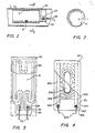
- FIGS. 1 and 2 show in section a part of a styling shaft 1 of a styling rod according to the invention. It is not shown that here the styling bar is provided with a handle and that the styling shaft 1 is connected at one end to the handle. But this is the usual design of a styling stick. In any case, hair to be styled can be wrapped around the styling shaft 1.
- the hairdressing shaft 1 is tubular and, in the exemplary embodiment shown and preferred here, is made of metal and is preferably thermally insulated from the handle.
- an electric heater is housed inside. This electric heater points a resistance heating element 2 housed in the hairdressing shaft 1 and shown in FIGS. 1 and 2.
- the resistance heating element 2 is provided with connections 24 for connecting lines 23, which lead to an electrical current source, for example a mains connection, but also an accumulator.
- an electrical current source for example a mains connection, but also an accumulator.
- the styling shaft 1 is made of metal, the resistance heating element 2 is provided with insulation to protect against contact with electrically conductive parts of the styling rod. However, this cannot be seen in FIGS. 1 and 2.
- the hairdressing shaft 1 can, however, also consist of non-metallic, in particular electrically insulating material, in which case a corresponding insulation on this side of the resistance heating element 2 is not necessary.
- the resistance heating element 2 is pressed with the aid of the spring element 3 designed as an adapter sleeve against the inner wall of the styling shaft 1, which can be seen particularly well from FIG. 2.
- the resistance heating element 2 can be designed as shown in FIG. 3 or as shown in FIG. 4, but can also be designed differently, provided that it is sufficiently electrically insulated in the areas in which metal parts are in contact or are to be feared. It is also essential that the resistance heating element 2 is sufficiently elastic and flexible to be able to fit closely against the inner wall of the styling shaft 1 of the styling rod, so that good heat transfer takes place. 1 shows that only the resistance areas of the resistance heating element 2 are clamped between the styling shaft 1 and the spring element 3, but that electrically conductive connection areas 26 of the resistance heating element 2 are not clamped.
- a resistance heating element 2 which comprises a support 21, here an approximately 1.3 mm thick Nomex paper (a paper consisting of heat-resistant polyamide fibers, Wz. Du Pont), and a heating resistor 22, here a thin metal foil, namely an approximately 0.25 mm thick nickel foil.
- the heating resistor 22 is punched out and glued to the carrier 21 and, in the exemplary embodiment shown here, guided in a loop shape such that there are six short parallel strips in the lower region in FIG. 3 and four short parallel strips in the upper region in FIG. 3, whereas only two parallel strips are present in the central region are available.
- the heating resistor 22 ends in two large integrated connection areas 26, in which two lines 23 are connected in an electrically conductive and mechanically fixed manner by means of ring-shaped connections 24 and eyelets 25.
- the eyelets 25 are driven both by the heating resistor 22 designed as nickel foil and by the carrier 21 designed as Nomex paper, so that the stronger Nomex paper prevents the lines 23 from pulling the heating resistor 22 when they are pulled.
- the resistance heating element 2 including the connections 24 has been electrically insulated with a thin insulating film 28.
- the insulating film 28 consists of an approximately 0.25 mm thick polyimide film. This is an electrically good insulating, heat-resistant and good heat-conducting material.
- the polyimide side that is to say the side of the resistance heating element 2 protected with the insulating film 28, faces the hairstyle shaft 1 in the hairdressing shaft 1 provided here, whereas the less thermally conductive Nomex paper side, that is to say the carrier 21, faces the spring element 3. In this way it is ensured that the heat generated is essentially transferred to the styling shaft 1.
- the Nomex paper side that is to say the carrier 21, is not electrically insulated on the side facing away from the heating resistor 22, at least not in the areas in which the eyelets 25 are arranged, the feature explained above is of importance that the spring element 3 is itself does not extend into the connection areas 26, since the spring element 3, consisting of metallic material, would otherwise short-circuit the connections 24.
- the resistance heating element 2 shown in FIG. 4 in a further embodiment consists of a carrier 201 made of heat-resistant, flexible and electrically insulating material, for example Nomex paper, impregnated glass fiber fabric, polyimide film, Teflon film.
- the carrier 201 is coated on its upper side with a heating resistor 202 of predetermined resistance.
- this coating forming the heating resistor 202 is a dispersion of carbon or graphite particles in a polymeric resin. The specific resistance is measured in ⁇ cm.
- two approximately parallel strips 203 of electrically conductive material are arranged on the carrier on the edge of the coating forming the essential part of the heating resistor 202.
- these are silver or nickel particles which are suspended in a thermosetting resin.
- the strips 203 extend further than the coating forming the heating resistor 202 and form two connection regions 204.
- Insulated lines 205 are electrically conductively connected on both connection regions 204, with the aid of connections 206.
- the coating which essentially forms the heating resistor 202 shows in its A free area 208 in the middle. This free area 208 can be formed, for example, by an elongated hole. It is only essential, however, that there is no coating forming the heating resistor 202 here.
- connection regions 204 and the strips 203 If a voltage is applied to the connection regions 204 and the strips 203, electrical current flows through the heating resistor 202 in the form of a coating, approximately along the current flow lines 209.
- the heat density which is generated by this current distribution in the heating resistor 202 corresponds to the current density, so that in more heat is generated in the end regions of the resistance heating element 2 than in the central region.
- An insulating film 210 which is heat-resistant, flexible and electrically insulating, covers the entire resistance heating element 2 including the connection regions 204, connections 206 and eyelets 207.
- the resistance heating element 503 generates heat uniformly over the entire heating area 502.
- the resistance heating element 603 is designed so that the heat generation is concentrated in the end regions of the heating region 602.
- the resulting temperature distributions in the styling shaft 1 are shown in the curves 504 and 604.
- the region “x” of the styling shaft 501 with temperatures above 150 ° C. is quite narrow in comparison with the region “y” of the styling shaft 601.
- Die Areas 505 and 605 under curves 504 and 604, which are proportional to the heat losses, however, are similar in size, so that it follows that with the resistance heating element 603, the heat output is implemented more efficiently.
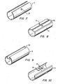
- FIG. 7, 8, 9 and 10 show four different exemplary embodiments of a spring element 3 for a styling stick according to the teaching of the invention.
- the exemplary embodiments differ in how the respective spring element 3, designed as an adapter sleeve, is pulled together for insertion into the styling shaft 1.
- a variety of other embodiments are conceivable.
- the spring element 3 designed as an adapter sleeve is provided in all cases near the edges of the longitudinal slot provided in all cases with engagement formations 32 or engagement openings 31 for an insertion tool, which is not shown, however.
- the engagement formations 32 are sometimes also flange-like areas in which the engagement openings 31 are then formed (FIGS. 8 and 10).
- the spring element 3 designed as an adapter sleeve can be reduced in diameter in the exemplary embodiments shown here for insertion into the hairdressing shaft 1, that is to say it can be contracted.
- the spring element 3 then springs back into its normal state after use in the styling shaft 1, as a result of which the resistance heating element 2 is pressed against the styling shaft 1 from the inside.
- the resistance heating element 2 can also be glued to the outside of the spring element 3 before it is inserted into the styling shaft 1.
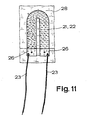
- Fig. 11 makes another, particularly preferred embodiment of the invention clear, which is characterized in that the carrier 21 consists of a paper or a paper-like material, in the preferred embodiment shown here and consists of a heat-resistant synthetic fiber fabric or synthetic fiber pressed body, in particular made of polyamide, and that the heating resistor 22 is designed as an impregnation of the carrier 21 consisting of fine carbon or graphite particles in a dispersion.
- This embodiment of the resistance heating element 2 according to the invention is particularly expedient in terms of production technology.
- the heating resistor 22 is in fact obtained here in its final form by cutting out the essentially U-shaped support 21, which can be seen in FIG. 11, from a large, fully impregnated support 21. So here carrier 21 and heating resistor 22 are fused into an inseparable unit. Nomex paper can also be used as the material here.
- connection regions 26 for connecting lines 23 deserve special attention.
- the connection areas 26 can, for example, as additional coatings made of electrically conductive material or as thin, applied metal foils pressed by external pressure on the corresponding areas of the heating resistor 22 or as folded in the corresponding areas around the heating resistor 22 and connected to both sides, in particular perforated and metal foils soldered from both sides. The latter is shown in Fig. 11. In any case, the lines 23 are then soldered, clamped or otherwise connected in an electrically conductive manner to the connection regions 26.
- the resistance heating element 2 consists of the flat, flexible heating resistor 22 and two insulating foils 28, which are connected on both sides to the heating resistor 22 and which can be configured in terms of material in the manner explained above.
Abstract
Bei einem Frisierstab mit einem Handgriff, einem an einem Ende an den Handgriff angeschlossenen, rohrförmigen Frisierschaft (1) und einer Elektroheizung, bei dem die Elektroheizung ein im Frisierschaft (1) angeordnetes Widerstandsheizelement (2) aufweist, das Widerstandsheizelement (2) mit Anschlußbereichen zum Anschluß einer elektrischen Stromquelle versehen ist und ggf. eine Isolation zum Schutz gegen Berührung von elektrisch leitenden Teilen vorhanden ist, werden eine kurze Aufheizzeit, eine stabile, sich selbst haltende Temperatur gleichzeitig mit sehr niedrigen Herstellungskosten dadurch erreicht, daß das Widerstandsheizelement (2) als flächenhaftes, biegsames, vorzugsweise federelstisches Bauteil mit einem flächenhaften, biegsamen Heizwiderstand ausgeführt, in einer der Form des Frisierschafts (1) etwa entsprechenden, vorzugsweise kreiszylindrisch-mantelförmigen Form gebogen in den Frisierschaft (1) eingesetzt und im wesentlichen mit seiner vollen Fläche unmittelbar an der Innenwand des Frisierschafts (1) anliegend angeordnet ist und daß ein das Widerstandsheizelement (2) an der Innenwand des Frisierschafts (1) anpressendes, einen guten Wärmeübergang vom Widerstandsheizelement (2) auf den Frisierschaft (1) gewährleistendes Federelement (3) vorgesehen ist.In a styling bar with a handle, a tubular styling shaft (1) connected to the handle at one end and an electric heater, in which the electric heater has a resistance heating element (2) arranged in the styling shaft (1), the resistance heating element (2) with connection areas for Connection of an electrical power source is provided and, if necessary, insulation to protect against contact with electrically conductive parts, a short heating-up time, a stable, self-maintaining temperature are achieved at the same time with very low manufacturing costs in that the resistance heating element (2) is flat , Flexible, preferably resilient component with a planar, flexible heating resistor, in a shape corresponding to the shape of the hairdressing shaft (1), preferably circular-cylindrical-shaped shape bent into the hairdressing shaft (1) and used essentially with its full area directly on the inside and the hairdressing shaft (1) is arranged adjacent and that the resistance heating element (2) on the inner wall of the hairdressing shaft (1) pressing, a good heat transfer from the resistance heating element (2) to the hairdressing shaft (1) is provided spring element (3).
Description
Die Erfindung betrifft einen Frisierstab mit einer Elektroheizung, insbesondere einen Frisierstab mit einem Handgriff, einem an einem Ende an den Handgriff angeschlossenen, rohrförmigen, vorzugsweise aus Metall bestehenden und/oder gegenüber dem Handgriff wärmeisolierten Frisierschaft und einer Elektroheizung, wobei zum Frisieren zu frisierende Haare um den Frisierschaft wickelbar sind und wobei die Elektroheizung ein im Frisierschaft angeordnetes Widerstandsheizelement aufweist, das Widerstandsheizelement mit Anschlußbereichen zum Anschluß einer elektrischen Stromquelle versehen ist und das Widerstandsheizelement zum Schutz gegen Berührungen mit elektrisch leitenden Teilen des Frisierstabs so weit wie notwendig mit einer Isolation versehen ist.The invention relates to a hair styling bar with an electric heater, in particular a hair styling bar with a handle, a tubular, preferably made of metal and / or heat-insulated hair styling shaft connected to the handle at one end and an electric heater, with hair to be styled around the hair styling shaft can be wound and wherein the electric heater has a resistance heating element arranged in the hair styling shaft, the resistance heating element is provided with connection areas for connecting an electrical power source and the resistance heating element is provided with insulation as far as necessary to protect against contact with electrically conductive parts of the hair styling rod.
Übliche Frisierstäbe der zuvor erläuterten Art dienen zum Aufwickeln zu frisierender Haare während des Frisierens und sind zumeist zusätzlich mit einer Einrichtung zum Erfassen einer Strähne versehen. Diese Einrichtungen können eine federbelastete Klammer sein, die einen Teil des Frisierschafts unter Federbelastung umfaßt, es kann sich aber auch um Zahnreihen oder Kammreihen handeln, die am Frisierschaft angebracht oder integral mit dem Frisierschaft ausgeführt sind. Schließlich kann es sich auch um Bürstchen handeln, die aus dem Frisierschaft gewissermaßen eine zylindrische Bürste entstehen lassen.Usual hairstyling sticks of the type explained above are used to wind up hair to be styled during the hairstyling and are usually additionally provided with a device for grasping a strand. These devices can be a spring-loaded clip which comprises part of the hairdressing shaft under spring load, but can also be rows of teeth or rows of combs which are attached to the hairdressing shaft or are embodied integrally with the hairdressing shaft. Finally, it can also be a brush, which can be used to create a cylindrical brush from the hairdressing shaft.
Die um dem Frisierschaft gewickelten Haare werden der Wärme des Frisierstabs ausgesetzt. Diese Wärme, unterstützt von verschiedenen kosmetischen Flüssigkeiten für die Haare, bewirkt, daß eine Haarsträhne auch nach Freigabe vom Frisierstab ihren Lockenzustand beibehält. Üblicherweise ist der Frisierschaft länger als die zu erwartende Breite der um den Frisierschaft zu wickelnden Haarsträhne. Aus diesem Grunde wird nur der mittlere Bereich des Frisierschafts auf die höchste zulässige Temperatur aufgeheizt, wäh rend die Endbereiche nahe dem Handgriff einerseits und entfernt vom Handgriff andererseits relativ kühl bleiben.The hair wrapped around the hairdressing shaft is exposed to the warmth of the styling stick. This warmth, supported by various cosmetic liquids for the hair, causes a strand of hair to retain its curly state even after being released from the styling rod. The hairstyle is usually longer than the expected width of the strand of hair to be wrapped around the hairstyle. For this reason, only the middle area of the hairdressing shaft is heated to the highest permissible temperature, weh The end areas near the handle on the one hand and away from the handle on the other hand remain relatively cool.
Die aus dem Stand der Technik bekannten Frisierstäbe können hinsichtlich der Art des Widerstandsheizelements wie folgt beschrieben werden:The styling rods known from the prior art can be described as follows with regard to the type of resistance heating element:
Das Widerstandsheizelement ist bei manchen Frisierstäben als kabelartiger Heizleiter ausgeführt, der mittig in den Frisierschaft eingeführt ist und sich über etwa zwei Drittel der Länge des Frisierschafts erstreckt. Nachteilig ist bei dieser Konstruktion, daß der Heizleiter sich nur in Punktkontakt mit der Innenwand des Frisierschafts an einer Vielzahl von Punkten befindet. Dadurch ist der Wärmeübergang relativ schlecht. Ein solcher Frisierstab bedarf einer langen Aufheizzeit. Außerdem muß bei einem solchen Frisierstab die Wanddicke des Frisierschafts relativ groß sein, damit ein Temperaturausgleich über den interessierenden Bereich stattfindet. Außerdem wird hier die maximale Temperatur mittig im Frisierschaft erreicht und fällt von da aus zu den Enden hin ab.The resistance heating element in some hairdressing rods is designed as a cable-like heating conductor which is inserted in the center of the hairdressing shaft and extends over approximately two thirds of the length of the hairdressing shaft. A disadvantage of this construction is that the heating conductor is only in point contact with the inner wall of the hairdressing shaft at a large number of points. As a result, the heat transfer is relatively poor. Such a styling rod takes a long time to heat up. In addition, the wall thickness of the styling shaft must be relatively large in such a styling bar so that a temperature compensation takes place over the area of interest. In addition, the maximum temperature is reached in the middle of the hairdressing shaft and drops from there to the ends.
Bekannt sind auch Frisierstäbe mit einem PTC-Element, einem Halbleiterelement mit positivem Temperaturkoeffizienten, das in einem zylindrischen Körper aus isolierendem Material eingebettet ist. Der zylindrische Körper aus isolierendem Material entspricht mit seinem Durchmesser etwa dem Innendurchmesser des Frisierschafts und nimmt etwa 50 % der Gesamtlänge des Frisierschafts ein. Das hier verwendete Widerstandsheizelement ist erheblich zweckmäßiger als der zuvor erläuterte Heizleiter, insbesondere unter Berücksichtigung der Überhitzungsgefahr. Wegen des zylindrischen Körpers aus elektrisch isolierendem, jedoch wärmeleitendem Material ist auch der Wärmeübergang vom Widerstandsheizelement auf den Frisierschaft erheblich besser als beim zuvor erläuterten Heizleiter. Allerdings ist diese Konstruktion ziemlich teuer und kann daher bei preislich niedrig liegenden Frisierstäben nicht verwendet werden. Im übrigen muß auch bei dieser Lösung der Frisierschaft eine relativ große Wandstärke aufweisen, um eine gleichmäßige Temperaturverteilung zu gewährleisten, da auch hier die maximale Temperatur im mittleren Bereich des Widerstandsheizelements und damit im mittleren Bereich des Frisierschafts erreicht wird. Von dort aus fällt die Temperatur langsam zu den Enden des Frisierschafts ab.Also known are styling rods with a PTC element, a semiconductor element with a positive temperature coefficient, which is embedded in a cylindrical body made of insulating material. The diameter of the cylindrical body made of insulating material corresponds approximately to the inside diameter of the styling shaft and takes up approximately 50% of the total length of the styling shaft. The resistance heating element used here is considerably more expedient than the previously explained heat conductor, especially taking into account the risk of overheating. Because of the cylindrical body made of electrically insulating but heat-conducting material, the heat transfer from the resistance heating element to the hairdressing shaft is also considerably better than with the previously explained heating conductor. However, this construction is quite expensive and can therefore not be used with low-priced styling sticks. Moreover, the hairdressing shaft must also have a relatively large wall thickness in this solution in order to ensure an even temperature distribution, since here too maximum temperature is reached in the central area of the resistance heating element and thus in the central area of the hairdressing shaft. From there, the temperature slowly drops to the ends of the hairdressing shaft.
Unter Berücksichtigung der zuvor erläuterten bekannten Frisierstäbe liegt der Erfindung die Aufgabe zugrunde, einen Frisierstab anzugeben, bei dem das Widerstandsheizelement in besonders gutem Wärmekontakt mit der Innenwand des Frisierschafts steht, und zwar über die volle Länge des Widerstandsheizelements.Taking into account the known styling rods explained above, the object of the invention is to provide a styling rod in which the resistance heating element is in particularly good thermal contact with the inner wall of the styling shaft over the full length of the resistance heating element.
Der erfindungsgemäße Frisierstab, bei dem die zuvor aufgezeigte Aufgabe gelöst ist, ist dadurch gekennzeichnet, daß das Widerstandsheizelement als flächenhaftes, biegsames, vorzugsweise federelastisches Bauteil mit einem flächenhaften, biegsamen Heizwiderstand ausgeführt, in einer der Form des Frisierschafts etwa entsprechenden, vorzugsweise kreiszylindrisch-mantelförmigen Form gebogen in den Frisierschaft eingesetzt und im wesentlichen mit seiner vollen Fläche unmittelbar an der Innenwand des Frisierschafts anliegend angeordnet ist und daß ein das Widerstandsheizelement an die Innenwand des Frisierschafts anpressendes, einen guten Wärmeübergang vom Widerstandsheizelement auf den Frisierschaft gewährleistendes Federelement vorgesehen ist.The hairdressing rod according to the invention, in which the above-mentioned object is achieved, is characterized in that the resistance heating element is designed as a flat, flexible, preferably spring-elastic component with a flat, flexible heating resistor, in a shape that approximately corresponds to the shape of the hairdressing shaft, preferably a circular cylindrical, jacket-shaped shape bent used in the hairdressing shaft and is arranged with its entire surface directly adjacent to the inner wall of the hairdressing shaft and that a spring element is provided which presses the resistance heating element against the inner wall of the hairdressing shaft and ensures good heat transfer from the resistance heating element to the hairdressing shaft.
Erfindungsgemäß ist der Frisierstab so ausgestaltet, daß der bestmögliche Wärmekontakt zwischen Widerstandsheizelement und Innenwand des Frisierschafts besteht, wobei das Widerstandsheizelement selbst eine extrem geringe Wärmekapazität hat und ganz gleichmäßig über seine volle Fläche Wärme auf den Frisierschaft überträgt. Dadurch wird erreicht, daß der Frisierschaft sehr dünnwandig ausgeführt werden kann, was Kosten spart und gleichzeitig die Wärmekapazität weiter verringert. Dadurch wird die Aufheizzeit gegenüber dem Stand der Technik erheblich verkürzt. Im übrigen läßt sich mit der Erfindung erreichen, daß der Mittelbereich des Frisierschafts eine weitestgehend gleichmäßige Temperatur hat und daß diese Temperatur während des gesamten Frisierens mehr oder weniger gleich bleibt. Durch entsprechende Gestaltung des erfindungsgemäß als flächenhaftes, biegsames, extrem dünnes Element ausgeführten Heizwiderstands läßt sich erreichen, daß das Material des Heizwiderstands einen hohen, positiven Temperaturkoeffizienten für den elektrischen Widerstand hat. Dadurch kann mann unter Umständen sogar auf einen Thermostatschalter verzichten und gleichwohl eine Überhitzung des Frisierschafts vermeiden.According to the styling bar is designed so that there is the best possible thermal contact between the resistance heating element and the inner wall of the styling shaft, the resistance heating element itself having an extremely low heat capacity and transmitting heat uniformly over its full area to the styling shaft. This ensures that the hairdressing shaft can be made very thin-walled, which saves costs and at the same time further reduces the heat capacity. As a result, the heating-up time is considerably reduced compared to the prior art. In addition, it can be achieved with the invention that the central region of the hairdressing shaft has a largely uniform temperature and that this temperature is more or less the same throughout the hairdressing remains. By appropriate design of the heating resistor designed according to the invention as a flat, flexible, extremely thin element, it can be achieved that the material of the heating resistor has a high, positive temperature coefficient for the electrical resistance. In this way, you can even do without a thermostat switch and avoid overheating the hairdressing shaft.
Vorteilhafte Ausgestaltungen und Weiterbildungen der Lehre der Erfindung werden in den dem Anspruch 1 nachgeordneten Ansprüchen beschrieben. Im enzelnen darf ergänzend noch folgendes erläutert werden.Advantageous refinements and developments of the teaching of the invention are described in the claims subordinate to claim 1. The following may also be explained in detail.
Die Merkmale des Anspruchs 2 führen dazu, daß die Wärmeentwicklung in den Endbereichen größer ist als im dazwischen liegenden mittleren Bereich des Widerstandsheizelements, so daß sich insgesamt über die Gesamtlänge des beheizten Bereichs des Frisierschafts eine weitestgehend gleichmäßige Temperaturverteilung ergibt. Wie das im einzelnen für einen in Schleifenform geführten Heizwiderstand erreicht werden kann, wird in Anspruch 3 beschrieben. Hierbei kann der Heizwiderstand insbesondere als Metallfolie, insbesondere aus Nickel oder einer Nickel-Verbindung, ausgeführt bzw. aus einer solchen Metallfolie geschnitten sein, wie Anspruch 4 zeigt. In jedem Fall sollte das Material des Heizwiderstands so gewählt sein, daß es einen hohen, positiven Temperaturkoeffizienten des elektrischen Widerstands aufweist. Das bedeutet, daß der Heizwiderstand sich schnell auf die gewünschte Temperatur aufheizt und während der gesamten Zeit der Einschaltung diese Temperatur beibehält. Ein solches Material ist beispielsweise Nickel. Andere Materialien mit entsprechend positivem Temperaturkoeffizienten des elektrischen Widerstand sind natürlich gleichfalls verwendbar.The features of
Von besonderem praktischen Wert ist die dritte Alternative im Anspruch 4, bei der der Träger mit dem Heizwiderstand gemeinsam integriert ist. Dieses Widerstandsheizelement läßt sich fertigungstechnisch gemäß Anspruch 5 in besonders zweckmäßiger Weise gestalten.Of particular practical value is the third alternative in claim 4, in which the carrier is integrated together with the heating resistor. This resistance heating element can be designed in a particularly expedient manner in terms of production technology.
Eine ebenfalls sehr zweckmäßige Konstruktion des bei dem erfindungsgemäßen Frisierstab verwendeten Widerstandsheizelements ist in Anspruch 6 beschrieben. Die hier vorzugsweise erläuterten Materialien für die Streifen einerseits und die zwischen den Streifen liegende Beschichtung andererseits erfüllen die zuvor erläuterten Erfordernisse hinsichtlich des Temperaturkoeffizienten ebenso wie die herstellungstechnischen Erfordernisse. Selbstverständlich können die Streifen ohne weiteres auch aus Metallschichten, beispielsweise Silber oder Kupfer, bestehen.A very useful construction of the resistance heating element used in the styling bar according to the invention is described in claim 6. The materials for the strips, which are preferably explained here, on the one hand, and the coating lying between the strips, on the other hand, meet the previously explained requirements with regard to the temperature coefficient as well as the manufacturing requirements. The strips can of course also consist of metal layers, for example silver or copper.
Anspruch 7 erläutert die hinsichtlich des Berührungsschutzes von metallischen Teilen empfehlenswerte Isolation des Heizwiderstands. Besteht der Frisierschaft aus einem elektrisch leitenden Material, insbesondere also aus Metall, so ist eine Isolierschicht oder Isolierfolie auf der am Frisierschaft zur Anlage kommenden Seite des Heizwiderstands zwingend erforderlich. Ist hingegen der Frisierschaft aus elektrisch isolierendem Material hergestellt, so ist die Isolierschicht bzw. Isolierfolie auf dieser Seite nicht zwingend. Entsprechendes gilt auf der gegenüberliegenden Seite des Heizwiderstands. Die Isolierfolie bzw. die Isolierfolien können mit dem Heizwiderstand verklebt sein, sie können aber auch als integrale Beschichtungen auf dem Heizwiderstand ausgeführt sein. Auch ist es möglich, den Heizwiderstand zwischen zwei Isolierfolien einzuschweißen oder aber lediglich Isolierfolie und Heizwiderstand locker aufeinanderzuschichten. Im zuletztgenannten Fall dürften aber evtl. Probleme beim Zusammensetzen des Frisierstabs auftreten.
Verschiedene Formen der Ausgestaltung der Anschlußbereiche an einem Widerstandshiezelement eines erfindungsgemäßen Frisierstabs beschreibt Anspruch 8, selbstverständlich ohne Anspruch auf Vollständigkeit,Various forms of the configuration of the connection areas on a resistance heating element of a styling bar according to the invention are described in claim 8, of course without claim to completeness,
Anspruch 9 erläutert eine noch besonders zweckmäßige Gestaltung des erfindungsgemäßen Frisierstabs, die davon ausgeht, daß ein solcher Frisierstab wahlweise am Netz oder mit einem Akkumulator betrieben werden soll.Claim 9 explains a still particularly expedient design of the styling rod according to the invention, which assumes that such a styling rod should be operated either on the network or with an accumulator.
Die beiden hierzu vorgesehenen Heizwiderstände, die jeweils für sich so ausgeführt sein können wie das zuvor in verschiedensten Alternativen erläutert worden ist, sollten logischerweise den zu erwartenden Anschlußspannungen entsprechende unterschiedliche Widerstandswerte aufweisen. Im im Anspruch 9 vorzugsweise angegebenen Ausführungsbeispiel sind die beiden Heizwiderstände gewissermaßen zu einem einzigen doppelten Widerstandsheizelement integriert und auf ein und demselben Träger angeordnet. Es sind dann vier Anschlußbereiche für elektrische Leitungen vorhanden. Die Heizwiderstände können nebeneinander auf ein und derselben Seite des Trägers oder auch auf gegenüberliegenden Seiten des Trägers angeordnet sein. Der Träger kann dann eine Isolierung der beiden Heizwiderstände bilden. In allen Fällen sind natürlich entsprechende Isolierschichten bzw. Isolierfolien zu verwenden. Schließlich ist es natürlich ohne weiteres möglich, zwei getrennte Widerstandsheizelemente mit jeweils einem Heizwiderstand vorzusehen, also gewissermaßen mit einem doppellagigen System zwischen Federelement und Frisierschaft zu arbeiten.The two heating resistors provided for this purpose, each of which can be designed as it has been explained in various alternatives, should logically have different resistance values corresponding to the connection voltages to be expected. In the exemplary embodiment preferably specified in claim 9, the two heating resistors are, so to speak, integrated into a single double resistance heating element and arranged on one and the same carrier. There are then four connection areas for electrical lines. The heating resistors can be arranged side by side on one and the same side of the carrier or on opposite sides of the carrier. The carrier can then form an insulation of the two heating resistors. Corresponding insulating layers or foils are of course to be used in all cases. Finally, it is of course readily possible to provide two separate resistance heating elements, each with a heating resistor, that is to say to work with a double-layer system between the spring element and the hairdressing shaft.
Hinsichtlich des Federelements beschreibt schließlich Anspruch 10 eine besonders zweckmäßige Gestaltung.With regard to the spring element, claim 10 finally describes a particularly expedient design.
Die Erläuterung bevorzugter Ausführungsbeispiele anhand der Zeichnung gibt im übrigen weiteren Aufschluß über Vorteile und Wirkungen beim erfindungsgemäßen Frisierstab.The explanation of preferred exemplary embodiments with reference to the drawing provides further information about the advantages and effects of the styling stick according to the invention.
Im folgenden wird die Erfindung anhand einer lediglich Ausführungsbeispiele darstellenden Zeichnung näher erläutert; es zeigt
- Fig. 1 in einem Längsschnitt einen Teil eines Frisierschafts eines erfindungsgemäßen Frisierstabs mit eingesetztem Widerstandsheizelement und eingesetztem Federelement,
- Fig. 2 einen Schnitt durch den Gegenstand aus Fig. 1 entlang der Linie 2-2 in Fig. 1,
- Fig. 3 eine Abwicklung eines Widerstandsheizelements mit einen schleifenförming geführten, streifenartigen Heizwiderstand,
- Fig. 4 eine Draufsicht auf einen Widerstand, der aus einem folienartigen Träger aus isolierendem Material mit leitendem und einen bestimmten Widerstand aufweisendem Material besteht,
- Fig. 5 die Temperaturverteilung in einem Frisierschaft mit einem Widerstandselement, das über seine Länge eine gleichmäßige Wärmeentwicklung zeigt,
- Fig. 6 die Temperaturverteilung in einem Frisierschaft mit einem Widerstandselement, das über seine Länge eine ungleichmäßige Wärmeentwicklung zeigt,
- Fig. 7 bis Fig. 10 perspektivische Darstellungen von vier unterschiedlichen Federelementen zur Verwendung in einem erfindungsgemäßen Frisierstab und
- Fig. 11 in Draufsicht ein Widerstandsheizelement, das aus einem mit einer Imprägnierung feiner Kohlenstoff- oder Graphitteilchen versehenen Träger aus einem Papier oder papierähnlichen Material besteht.
- 1 shows in a longitudinal section a part of a styling shaft of a styling bar according to the invention with an inserted resistance heating element and an inserted spring element,
- 2 shows a section through the object from FIG. 1 along the line 2-2 in FIG. 1,
- 3 shows a development of a resistance heating element with a loop-shaped, strip-like heating resistor,
- 4 is a plan view of a resistor, which consists of a film-like carrier made of insulating material with conductive material and having a specific resistance,
- 5 shows the temperature distribution in a hairdressing shaft with a resistance element, which shows a uniform heat development over its length,
- 6 shows the temperature distribution in a hairdressing shaft with a resistance element which shows uneven heat development over its length,
- 7 to 10 are perspective views of four different spring elements for use in a styling bar according to the invention and
- 11 is a plan view of a resistance heating element which consists of a support made of paper or paper-like material and provided with an impregnation of fine carbon or graphite particles.
Die Fig. 1 und 2 zeigen im Schnitt einen Teil eines Frisierschafts 1 eines erfindungsgemäßen Frisierstabs. Nicht dargestellt ist, daß hier der Frisierstab mit einem Handgriff versehen ist und daß der Frisierschaft 1 an einem Ende an den Handgriff angeschlossen ist. Das ist aber die übliche Gestaltung eines Frisierstabs. Jedenfalls sind zum Frisieren zu frisierende Haare um den Frisierschaft 1 wickelbar. Der Frisierschaft 1 ist rohrförmig ausgebildet und besteht im hier dargestellten und bevorzugten Ausführungsbeispiel aus Metall und ist vorzugsweise gegenüber dem Handgriff wärmeisoliert. Wie bei derartigen Frisierstäben üblich ist im Inneren eine Elektroheizung untergebracht. Diese Elektroheizung weist ein im Frisierschaft 1 untergebrachtes, in Fig. 1 und Fig. 2 dargestelltes Widerstandsheizelement 2 auf. Das Widerstandsheizelement 2 ist mit Anschlüssen 24 zum Anschluß von Leitungen 23 versehen, die zu einer elektrischen Stromquelle, beispielsweise einem Netzanschluß, aber auch einem Akkumulator, führen. Grundsätzlich ist jedenfalls dann, wenn der Frisierschaft 1 aus Metall besteht, das Widerstandsheizelement 2 zum Schutz gegen Berührungen mit elektrisch leitenden Teilen des Frisierstabs mit einer Isolation versehen. Das ist allerdings in den Fig. 1 und 2 nicht erkennbar. Der Frisierschaft 1 kann im übrigen aber auch aus nicht-metallischem, insbesondere elektrisch isolierendem Material bestehen, wobei dann eine entsprechende Isolation auf dieser Seite des Widerstandsheizelements 2 nicht erforderlich ist.1 and 2 show in section a part of a
Das Widerstandsheizelement 2 wird mit Hilfe des als Spannhülse ausgeführten Federelements 3 gegen die Innenwand des Frisierschafts 1 gepreßt, was aus Fig. 2 besonders gut zu entnehmen ist. Das Widerstandsheizelement 2 kann wie in Fig. 3 oder wie in Fig. 4 gezeigt ausgeführt sein, kann aber auch andersartig gestaltet sein, vorausgesetzt, daß es in den Bereichen, in denen Berührungen von Metallteilen gegeben oder zu befürchten sind, ausreichend elektrisch isoliert ist. Wesentlich ist auch, daß das Widerstandsheizelement 2 ausreichend elastisch und biegsam ist, um sich eng an die Innenwand des Frisierschafts 1 des Frisierstabs anlegen zu können, so daß ein guter Wärmeübergang erfolgt. Fig. 1 zeigt, daß nur die Widerstandsbereiche des Widerstandsheizelements 2 zwischen dem Frisierschaft 1 und dem Federelement 3 eingeklemmt sind, daß aber elektrisch leitende Anschlußbereiche 26 des Widerstandsheizelements 2 nicht eingeklemmt sind.The
Fig. 3 zeigt ein erstes Ausführungsbeispiel eines Widerstandsheizelements 2, das aus einem Träger 21, hier ein etwa 1,3 mm dickes Nomexpapier (ein aus hitzebeständigen Polyamidfasern bestehendes Papier, Wz. Du Pont), und einem Heizwiderstand 22, hier eine dünne Metallfolie, nämlich eine ca. 0,25 mm dicke Nickelfolie, besteht. Der Heizwiderstand 22 ist ausgestanzt und auf den Träger 21 aufgeklebt und im hier dargestellten Ausführungsbeispiel so in Schleifenform geführt, daß im in Fig. 3 unteren Bereich sechs kurze parallele Streifen und im in Fig. 3 oberen Bereich vier kurze parallele Streifen vorliegen, wohingegen im mittleren Bereich lediglich zwei parallele Streifen vorliegen. Die Stromdichte insgesamt ist also in den beiden Endbereichen des Heizwiderstands 22 größer als in dem dazwischen liegenden Bereich, folglich wird in den Endbereichen mehr Wärme erzeugt als im mittleren Bereich. Der Heizwiderstand 22 läuft im hier dargestellten Ausführungsbeispiel in zwei großen integrierten Anschlußbereichen 26 aus, in denen zwei Leitungen 23 mit Hilfe von ringförmigen Anschlüssen 24 und Ösen 25 elektrisch leitend und mechanisch fest angeschlossen sind. Die Ösen 25 sind sowohl durch den als Nickelfolie ausgeführten Heizwiderstand 22 als auch durch den als Nomexpapier ausgeführten Träger 21 getrieben, so daß das stärkere Nomexpapier verhindert, daä die Leitungen 23 den Heizwiderstand 22 vorziehen, wenn an ihnen gezogen wird.3 shows a first exemplary embodiment of a
Wie in Fig. 3 dargestellt ist, ist das Widerstandsheizelement 2 einschließlich der Anschlüsse 24 mit einer dünnen Isolierfolie 28 elektrisch isoliert worden. Im vorliegenden Fall besteht die Isolierfolie 28 aus einem etwa 0,25 mm dicken Polyimid-Film. Das ist ein elektrisch gut isolierendes, hitzebeständiges und gut wärmeleitendes Material. Die Polyimidseite, also die mit der Isolierfolie 28 geschützte Seite des Widerstandsheizelements 2, ist bei dem hier vorausgesetzten Frisierschaft 1 aus Metall diesem Frisierschaft 1 zugewandt, wohingegen die weniger gut wärmeleitende Nomexpapierseite, also der Träger 21, dem Federelement 3 zugewandt ist. Auf diese Weise ist sichergestellt, daß die erzeugte Wärme im wesentlichen auf den Frisierschaft 1 übertragen wird. Da die Nomexpapierseite, also der Träger 21, auf der vom Heizwiderstand 22 abgewandten Seite, nicht elektrisch isoliert ist, jedenfalls nicht in den Bereichen, in denen die Ösen 25 angeordnet sind, ist das weiter oben erläuterte Merkmal von Bedeutung, daß das Federelement 3 sich nicht bis in die Anschlußbereiche 26 erstreckt, da das Federelement 3, aus metallischem Material bestehend, ansonten die Anschlüsse 24 kurzschließen würde.As shown in FIG. 3, the
Das in Fig. 4 in einem weiteren Ausführungsbeispiel dargestellte Widerstandsheizelement 2 besteht aus einem Träger 201 aus hitzebeständigem, biegsamen und elektrisch isolierendem Material, beispielsweise also Nomexpapier, imprägniertes Glasfasergewebe, Polyimid-Film, Teflon-Film. Der Träger 201 ist auf seiner Oberseite mit einem Heizwiderstand 202 vorgegebenen Widerstands beschichtet. Im dargestellten Ausführungsbeispiel ist diese den Heizwiderstand 202 bildende Beschichtung eine Dispersion von Kohlenstoff- oder Graphitteilchen in einem polymeren Harz. Der spezifische Widerstand wird in µΩcm gemessen. Im hier dargestellten Ausführungsbeispiel sind am Rande der den wesentlichen Teil des Heizwiderstands 202 bildenden Beschichtung auf dem Träger zwei etwa parallel zueinander verlaufende Streifen 203 aus elektrisch leitendem Material angeordnet. Es handelt sich hier im Ausführungsbeispiel und nach bevorzugter Lehre der Erfindung um Silber- oder Nickelteilchen, die in einem unter Wärmeeinwirkung abbindenden Harz suspendiert sind. Die Streifen 203 erstrecken sich weiter als die den Heizwiderstand 202 bildende Beschichtung und bilden zwei Anschlußbereiche 204. Auf beiden Anschlußbereichen 204 sind isolierte Leitungen 205 elektrisch leitend angeschlossen, und zwar mit Hilfe von Anschlüssen 206. Die den Heizwiderstand 202 im wesentlichen bildende Beschichtung zeigt in ihrer Mitte einen freien Bereich 208. Dieser freie Bereich 208 kann beispielsweise durch ein Langloch gebildet sein. Wesentlich ist allerdings nur, daß hier keine den Heizwiderstand 202 bildende Beschichtung vorhanden ist.The
Wird eine Spannung an die Anschlußbereiche 204 und die Streifen 203 angelegt, strömt elektrischer Strom durch den als Beschichtung ausgeführten Heizwiderstand 202 etwa entlang der Stromlauflinien 209. Die Wärmedichte, die durch diese Stromverteilung in dem Heizwiderstand 202 erzeugt wird, entspricht der Stromdichte, so daß in den Endbereichen des Widerstandsheizelements 2 mehr Wärme erzeugt wird als im mittleren Bereich. Eine Isolierfolie 210, die hitzebeständig, biegsam und elektrisch isolierend ist, deckt das gesamte Widerstandsheizelement 2 einschließlich der Anschlußbereiche 204, Anschlüsse 206 und Ösen 207 ab.If a voltage is applied to the
Die Fig. 5 und 6 zeigen Widerstandsheizelemente 503, 603 unterschiedlicher Gestalt. Das Widerstandsheizelement 503 erzeugt über den gesamten Heizbereich 502 gleichmäßig Wärme. Das Widerstandsheizelement 603 ist so konstruiert, daß die Wärmeerzeugung in den Endbereichen des Heizbereichs 602 konzentriert ist. Die sich daraus ergebenden Temperaturverteilungen im Frisierschaft 1 zeigen die Kurven 504 bzw. 604. Bei der Kurve 504 ist der Bereich "x" des Frisierschafts 501 mit Temperaturen über 150 ° C ziemlich schmal im Vergleich mit dem Bereich "y" des Frisierschafts 601. Die Bereiche 505 bzw. 605 unter den Kurven 504 bzw. 604, die zu den Wärmeverlusten proportional sind, ähneln sich hingegen in der Größe, so daß sich daraus ergibt, daß mit dem Widerstandsheizelement 603 die Wärmeleistung effizienter umgesetzt wird.5 and 6 show
Die Fig. 7, 8, 9 und 10 zeigen vier unterschiedliche Ausführungsbeispiele eines Federelements 3 für einen Frisierstab nach der Lehre der Erfindung. Die Ausführungsbeispiele unterscheiden sich dadurch, wie hier das Zusammenziehen des jeweils als Spannhülse ausgeführten Federelements 3 zum Einsetzen in den Frisierschaft 1 erfolgt. Eine Vielzahl anderer Ausführungsformen ist denkbar.7, 8, 9 and 10 show four different exemplary embodiments of a
Gut erkennbar ist, daß hier das als Spannhülse ausgeführte Federelement 3 in allen Fällen nahe den Rändern des in allen Fällen vorgesehenen Längsschlitzes mit Eingriffsausformungen 32 oder Eingriffsöffnungen 31 für ein Einsetzwerkzeug, das allerdings nicht dargestellt ist, versehen ist. Die Eingriffsausformungen 32 sind mitunter auch flanschartig erweiterte Bereiche, in denen dann die Eingriffsöffnungen 31 ausgebildet sind (Fig. 8 und Fig. 10). Mit Hilfe einer Zange mit nadelartigen, abgebogenen Spitzen als Einsetzwerkzeug kann das als Spannhülse ausgeführte Federelement 3 in den hier dargestellten Ausführungsbeispielen zum Einsetzen in den Frisierschaft 1 im Durchmesser verringert, also zusammengezogen werden. Das Federelement 3 federt dann nach Einsatz in den Frisierschaft 1 in seinen Normalzustand zurück, wodurch das Widerstandsheizelement 2 von innen her an den Frisierschaft 1 angedrückt wird. Um den Zusammenbau des erfindungsgemäßen Frisierstabs zu vereinfachen, kann das Widerstandsheizelement 2 durchaus auch auf die Außenseite des Federelements 3 aufgeleimt werden, bevor dieses in den Frisierschaft 1 eingesetzt wird.It can be clearly seen that here the
Fig. 11 macht ein weiteres, besonders bevorzugtes Ausführungsbeispiel der Erfindung deutlich, das sich dadurch auszeichnet, daß der Träger 21 aus einem Papier oder einem papierähnlichen Material, im hier dargestellten und bevorzugten Ausführungsbeispiel aus einem hitzebeständigen Kunstfasergewebe oder Kunstfaserpreßkörper, insbesondere aus Polyamid, besteht und daß der Heizwiderstand 22 als aus feinen Kohlenstoff- oder Graphitteilchen in einer Dispersion bestehende Imprägnierung des Trägers 21 ausgeführt ist. Diese Ausführungsform des erfindungsgemäßen Widerstandsheizelements 2 ist herstellungstechnisch besonders zweckmäßig. Der Heizwiderstand 22 wird nämlich hier in seiner endgültigen Form dadurch gewonnen, daß aus einem großflächigen, vollflächig imprägnierten Träger 21 der im wesentlichen U-förmig geformte Träger 21, den man in Fig. 11 erkennt, herausgeschnitten wird. Hier sind also Träger 21 und Heizwiderstand 22 zu einer untrennbaren Einheit verschmolzen. Als Material kann auch hier Nomexpapier dienen.Fig. 11 makes another, particularly preferred embodiment of the invention clear, which is characterized in that the
Bei allen zuvor erläuterten Ausführungsbeispielen, insbesondere aber bei dem Ausführungsbeispiel in Fig. 11 der Zeichnung, verdient die Ausgestaltung der Anschlußbereiche 26 zum Anschluß von Leitungen 23 besondere Beachtung. Die Anschlußbereiche 26 können beispielsweise als zusätzliche Beschichtungen aus elektrisch leitendem Material oder als dünne, aufgelegte und durch externen Druck auf die entsprechenden Bereiche des Heizwiderstands 22 gepreßte Metallfolien oder als in den entsprechenden Bereichen um den Heizwiderstand 22 gefaltete und mit beiden Seiten verbundene, insbesondere gelochte und von beiden Seiten verlötete, Metallfolien ausgeführt sein. Letzteres ist in Fig. 11 dargestellt. In jedem Fall sind die Leitungen 23 dann aufgelötet, angeklemmt oder anderweitig elektrisch leitend mit den Anschlußbereichen 26 verbunden.In all the exemplary embodiments explained above, but in particular in the exemplary embodiment in FIG. 11 of the drawing, the design of the
Im hier dargestellten und insoweit bevorzugten Ausführungsbeispiel besteht im übrigen das Widerstandsheizelement 2 aus dem flächenhaften, biegsamen Heizwiderstand 22 und zwei, beidseits mit dem Heizwiderstand 22 verbundenen Isolierfolien 28, die in der weiter oben erläuterten Weise materialmäßig ausgestaltet sein können.In the exemplary embodiment shown here and to that extent preferred, the
Claims (10)
Applications Claiming Priority (2)
| Application Number | Priority Date | Filing Date | Title |
|---|---|---|---|
| US781790 | 1985-09-30 | ||
| US06/781,790 US4697066A (en) | 1985-09-30 | 1985-09-30 | Electric hair curling waved with improved heating element arrangement |
Publications (2)
| Publication Number | Publication Date |
|---|---|
| EP0218797A2 true EP0218797A2 (en) | 1987-04-22 |
| EP0218797A3 EP0218797A3 (en) | 1988-07-20 |
Family
ID=25123950
Family Applications (1)
| Application Number | Title | Priority Date | Filing Date |
|---|---|---|---|
| EP86108834A Withdrawn EP0218797A3 (en) | 1985-09-30 | 1986-06-30 | Electrically heated curling iron |
Country Status (2)
| Country | Link |
|---|---|
| US (1) | US4697066A (en) |
| EP (1) | EP0218797A3 (en) |
Cited By (4)
| Publication number | Priority date | Publication date | Assignee | Title |
|---|---|---|---|---|
| EP0401441A1 (en) * | 1987-12-01 | 1990-12-12 | Giovanni Management Canada Ltd. | Battery powered electrical curling/brush iron |
| DE202006000670U1 (en) * | 2006-01-18 | 2007-05-31 | Wik Far East Ltd. | Resistance heating element for a hair styling device and hair styling device equipped therewith |
| DE102012201739A1 (en) * | 2012-02-06 | 2013-08-08 | BSH Bosch und Siemens Hausgeräte GmbH | Electric hair straightener |
| WO2023161601A1 (en) * | 2022-02-24 | 2023-08-31 | Dyson Technology Limited | A haircare appliance |
Families Citing this family (9)
| Publication number | Priority date | Publication date | Assignee | Title |
|---|---|---|---|---|
| JPS62167503A (en) * | 1986-01-20 | 1987-07-23 | 松下電工株式会社 | Hair curler |
| US5354967A (en) * | 1992-11-13 | 1994-10-11 | Helen Of Troy Corporation | Hair styling appliance heater and control |
| KR20040029920A (en) * | 2002-10-04 | 2004-04-08 | 홍성태 | Hair lot and Manufacturing Method Thereof |
| EP1592320A4 (en) * | 2003-01-16 | 2007-06-27 | Conair | A hair roller with a ceramic coating |
| WO2006101498A1 (en) * | 2005-03-18 | 2006-09-28 | Powerpulse Technologies, L.P. | Cutaneous heating element |
| FR2927233B1 (en) * | 2008-02-08 | 2011-11-11 | Oreal | DEVICE FOR THE APPLICATION OF A COSMETIC PRODUCT, COMPRISING A HEATING ORGAN |
| DE102009011685A1 (en) * | 2009-03-04 | 2010-09-09 | Andreas Stihl Ag & Co. Kg | Hand-held implement |
| SG2013057377A (en) * | 2013-07-26 | 2015-02-27 | Tai Wah Distributors Pte Ltd | Hair appliances heating mat |
| JP6347651B2 (en) * | 2014-04-10 | 2018-06-27 | 日本電産サンキョー株式会社 | Damper device and heater |
Citations (11)
| Publication number | Priority date | Publication date | Assignee | Title |
|---|---|---|---|---|
| GB119094A (en) * | 1917-09-20 | 1918-09-20 | William Netherton | Improvements in or relating to Hair-dressing Appliances. |
| US1336559A (en) * | 1918-08-07 | 1920-04-13 | Gutzwiller Herbert | Electric internal tube-heater |
| US1477602A (en) * | 1921-04-25 | 1923-12-18 | Simon Maurice | Electrical heating unit |
| US1555953A (en) * | 1921-04-25 | 1925-10-06 | Simon Maurice | Electrical heating unit and method of making same |
| US1674488A (en) * | 1922-12-20 | 1928-06-19 | Gen Electric | Electric heating unit |
| US2473183A (en) * | 1947-07-16 | 1949-06-14 | Bates Mfg Co | Electrically conductive fabric |
| US3129314A (en) * | 1960-08-01 | 1964-04-14 | Babcock & Wilcox Co | Electric heater |
| US3387248A (en) * | 1964-05-04 | 1968-06-04 | Midland Silicones Ltd | Flexible electrical heating devices |
| FR1553082A (en) * | 1967-11-29 | 1969-01-10 | ||
| DE2840360A1 (en) * | 1978-09-16 | 1980-04-03 | Braun Ag | Curling tongs with uniform overall heating along bar - incorporate resistance heating unit formed by metal oxide layer on inside |
| US4354092A (en) * | 1978-10-05 | 1982-10-12 | Matsushita Electric Industrial Co., Ltd. | Electric hair curling iron with rechargeable battery power supply |
Family Cites Families (3)
| Publication number | Priority date | Publication date | Assignee | Title |
|---|---|---|---|---|
| US1358219A (en) * | 1920-01-09 | 1920-11-09 | Edgar T Lancaster | Power plant |
| US2371696A (en) * | 1943-07-17 | 1945-03-20 | Cities Service Oil Co | Helical electric immersion heater |
| US2501417A (en) * | 1946-08-15 | 1950-03-21 | Smits Wytze Beye | Electrical tube-immersion heater |
-
1985
- 1985-09-30 US US06/781,790 patent/US4697066A/en not_active Expired - Fee Related
-
1986
- 1986-06-30 EP EP86108834A patent/EP0218797A3/en not_active Withdrawn
Patent Citations (11)
| Publication number | Priority date | Publication date | Assignee | Title |
|---|---|---|---|---|
| GB119094A (en) * | 1917-09-20 | 1918-09-20 | William Netherton | Improvements in or relating to Hair-dressing Appliances. |
| US1336559A (en) * | 1918-08-07 | 1920-04-13 | Gutzwiller Herbert | Electric internal tube-heater |
| US1477602A (en) * | 1921-04-25 | 1923-12-18 | Simon Maurice | Electrical heating unit |
| US1555953A (en) * | 1921-04-25 | 1925-10-06 | Simon Maurice | Electrical heating unit and method of making same |
| US1674488A (en) * | 1922-12-20 | 1928-06-19 | Gen Electric | Electric heating unit |
| US2473183A (en) * | 1947-07-16 | 1949-06-14 | Bates Mfg Co | Electrically conductive fabric |
| US3129314A (en) * | 1960-08-01 | 1964-04-14 | Babcock & Wilcox Co | Electric heater |
| US3387248A (en) * | 1964-05-04 | 1968-06-04 | Midland Silicones Ltd | Flexible electrical heating devices |
| FR1553082A (en) * | 1967-11-29 | 1969-01-10 | ||
| DE2840360A1 (en) * | 1978-09-16 | 1980-04-03 | Braun Ag | Curling tongs with uniform overall heating along bar - incorporate resistance heating unit formed by metal oxide layer on inside |
| US4354092A (en) * | 1978-10-05 | 1982-10-12 | Matsushita Electric Industrial Co., Ltd. | Electric hair curling iron with rechargeable battery power supply |
Cited By (6)
| Publication number | Priority date | Publication date | Assignee | Title |
|---|---|---|---|---|
| EP0401441A1 (en) * | 1987-12-01 | 1990-12-12 | Giovanni Management Canada Ltd. | Battery powered electrical curling/brush iron |
| DE202006000670U1 (en) * | 2006-01-18 | 2007-05-31 | Wik Far East Ltd. | Resistance heating element for a hair styling device and hair styling device equipped therewith |
| WO2007082903A1 (en) * | 2006-01-18 | 2007-07-26 | Wik Far East Ltd. | Resistance heating element for a hair-styling device and a hair-styling device equipped with said resistance heating element |
| DE102012201739A1 (en) * | 2012-02-06 | 2013-08-08 | BSH Bosch und Siemens Hausgeräte GmbH | Electric hair straightener |
| EP2622986A3 (en) * | 2012-02-06 | 2015-12-30 | BSH Hausgeräte GmbH | Electric hair straightener |
| WO2023161601A1 (en) * | 2022-02-24 | 2023-08-31 | Dyson Technology Limited | A haircare appliance |
Also Published As
| Publication number | Publication date |
|---|---|
| EP0218797A3 (en) | 1988-07-20 |
| US4697066A (en) | 1987-09-29 |
Similar Documents
| Publication | Publication Date | Title |
|---|---|---|
| EP0350528B1 (en) | Radiator | |
| EP0218797A2 (en) | Electrically heated curling iron | |
| DE2614433B2 (en) | Self-regulating heating element | |
| DE3433196A1 (en) | PTC RESISTANCE DEVICE | |
| EP0333906B1 (en) | PTC heating resistor | |
| DE2837316A1 (en) | HAIR DRYER AND METHOD FOR PRODUCING A HEATER FOR THIS HAIR DRYER | |
| DE1299089B (en) | Heating unit for electric iron | |
| DE2946842C2 (en) | A heating element made of PTC thermistor material consisting of a honeycomb body | |
| DE3102849C2 (en) | ||
| DE3207015A1 (en) | HEATING DEVICE FOR AT LEAST TWO HEATING TEMPERATURE LEVELS WITH AT LEAST TWO INDIVIDUAL PTC HEATING ELEMENTS | |
| DE3023644C2 (en) | Housing for an electrical ceramic PTC thermistor for vaporizing chemical disinfectant and / or insecticide substances | |
| DE2709413B2 (en) | ||
| EP2622986B1 (en) | Electric hair straightener | |
| DE2840360C2 (en) | ||
| DE2907763A1 (en) | Delayed action timer for electrical appliances - has nonlinear resistor held between wide bimetal strip and narrow conductor | |
| DE1640197B2 (en) | BIMETAL SWITCH | |
| DE3425208A1 (en) | Heating arrangement for electrical heating apparatuses having PTC heating elements | |
| DE2515897C3 (en) | Flexible electrical panel heating element | |
| AT207930B (en) | Heating element for heating the bimetal in thermal switching devices with bimetal release | |
| DE3204273C2 (en) | Contact element for interposing between heat-conducting parts of a device, in particular a housing for an electrical assembly | |
| DE3115047A1 (en) | Apparatus for liquefying a meltable adhesive | |
| DE3935054C2 (en) | ||
| DE2422681C3 (en) | Expansion bar | |
| DE1615286C3 (en) | Control device | |
| DE19512497C1 (en) | Through-flow electric heater |
Legal Events
| Date | Code | Title | Description |
|---|---|---|---|
| PUAI | Public reference made under article 153(3) epc to a published international application that has entered the european phase |
Free format text: ORIGINAL CODE: 0009012 |
|
| 17P | Request for examination filed |
Effective date: 19870105 |
|
| AK | Designated contracting states |
Kind code of ref document: A2 Designated state(s): AT BE CH DE FR GB IT LI LU NL SE |
|
| PUAL | Search report despatched |
Free format text: ORIGINAL CODE: 0009013 |
|
| STAA | Information on the status of an ep patent application or granted ep patent |
Free format text: STATUS: THE APPLICATION HAS BEEN WITHDRAWN |
|
| AK | Designated contracting states |
Kind code of ref document: A3 Designated state(s): AT BE CH DE FR GB IT LI LU NL SE |
|
| 18W | Application withdrawn |
Withdrawal date: 19880620 |