EP0217995A2 - A device that may be applied to perforating drills for the drilling of foundation holes,and the insertion and stabilization of reinforcement tubes - Google Patents
A device that may be applied to perforating drills for the drilling of foundation holes,and the insertion and stabilization of reinforcement tubes Download PDFInfo
- Publication number
- EP0217995A2 EP0217995A2 EP85830279A EP85830279A EP0217995A2 EP 0217995 A2 EP0217995 A2 EP 0217995A2 EP 85830279 A EP85830279 A EP 85830279A EP 85830279 A EP85830279 A EP 85830279A EP 0217995 A2 EP0217995 A2 EP 0217995A2
- Authority
- EP
- European Patent Office
- Prior art keywords
- tube
- drill
- reinforcement
- tongues
- expansion
- Prior art date
- Legal status (The legal status is an assumption and is not a legal conclusion. Google has not performed a legal analysis and makes no representation as to the accuracy of the status listed.)
- Withdrawn
Links
- 230000002787 reinforcement Effects 0.000 title claims abstract description 17
- 238000005553 drilling Methods 0.000 title claims abstract description 7
- 238000003780 insertion Methods 0.000 title claims description 4
- 230000037431 insertion Effects 0.000 title claims description 4
- 230000006641 stabilisation Effects 0.000 title claims description 4
- 238000011105 stabilization Methods 0.000 title claims description 4
- 210000002105 tongue Anatomy 0.000 claims abstract description 13
- 238000000605 extraction Methods 0.000 claims description 6
- 230000000284 resting effect Effects 0.000 claims description 2
- 230000035515 penetration Effects 0.000 abstract description 3
- 229910000831 Steel Inorganic materials 0.000 abstract description 2
- 239000004568 cement Substances 0.000 abstract description 2
- 239000010959 steel Substances 0.000 abstract description 2
- 230000000087 stabilizing effect Effects 0.000 abstract 1
- 239000000463 material Substances 0.000 description 4
- 238000009412 basement excavation Methods 0.000 description 2
- 230000008030 elimination Effects 0.000 description 1
- 238000003379 elimination reaction Methods 0.000 description 1
- 238000000034 method Methods 0.000 description 1
- 239000004576 sand Substances 0.000 description 1
- 238000004904 shortening Methods 0.000 description 1
Images


Classifications
-
- E—FIXED CONSTRUCTIONS
- E21—EARTH DRILLING; MINING
- E21B—EARTH DRILLING, e.g. DEEP DRILLING; OBTAINING OIL, GAS, WATER, SOLUBLE OR MELTABLE MATERIALS OR A SLURRY OF MINERALS FROM WELLS
- E21B10/00—Drill bits
- E21B10/44—Bits with helical conveying portion, e.g. screw type bits; Augers with leading portion or with detachable parts
-
- E—FIXED CONSTRUCTIONS
- E21—EARTH DRILLING; MINING
- E21B—EARTH DRILLING, e.g. DEEP DRILLING; OBTAINING OIL, GAS, WATER, SOLUBLE OR MELTABLE MATERIALS OR A SLURRY OF MINERALS FROM WELLS
- E21B10/00—Drill bits
- E21B10/26—Drill bits with leading portion, i.e. drill bits with a pilot cutter; Drill bits for enlarging the borehole, e.g. reamers
- E21B10/32—Drill bits with leading portion, i.e. drill bits with a pilot cutter; Drill bits for enlarging the borehole, e.g. reamers with expansible cutting tools
- E21B10/327—Drill bits with leading portion, i.e. drill bits with a pilot cutter; Drill bits for enlarging the borehole, e.g. reamers with expansible cutting tools the cutter being pivoted about a longitudinal axis
-
- E—FIXED CONSTRUCTIONS
- E02—HYDRAULIC ENGINEERING; FOUNDATIONS; SOIL SHIFTING
- E02D—FOUNDATIONS; EXCAVATIONS; EMBANKMENTS; UNDERGROUND OR UNDERWATER STRUCTURES
- E02D7/00—Methods or apparatus for placing sheet pile bulkheads, piles, mouldpipes, or other moulds
- E02D7/28—Placing of hollow pipes or mould pipes by means arranged inside the piles or pipes
-
- E—FIXED CONSTRUCTIONS
- E21—EARTH DRILLING; MINING
- E21B—EARTH DRILLING, e.g. DEEP DRILLING; OBTAINING OIL, GAS, WATER, SOLUBLE OR MELTABLE MATERIALS OR A SLURRY OF MINERALS FROM WELLS
- E21B17/00—Drilling rods or pipes; Flexible drill strings; Kellies; Drill collars; Sucker rods; Cables; Casings; Tubings
- E21B17/02—Couplings; joints
- E21B17/08—Casing joints
-
- E—FIXED CONSTRUCTIONS
- E21—EARTH DRILLING; MINING
- E21B—EARTH DRILLING, e.g. DEEP DRILLING; OBTAINING OIL, GAS, WATER, SOLUBLE OR MELTABLE MATERIALS OR A SLURRY OF MINERALS FROM WELLS
- E21B7/00—Special methods or apparatus for drilling
- E21B7/20—Driving or forcing casings or pipes into boreholes, e.g. sinking; Simultaneously drilling and casing boreholes
- E21B7/201—Driving or forcing casings or pipes into boreholes, e.g. sinking; Simultaneously drilling and casing boreholes with helical conveying means
Definitions
- the present invention concerns a device that may be applied to perforating drills for the drilling of foundation holes and the insertion and stabilization of reinforcement tubes of steel, cement and other materials.
- the aim is reached by means of the device according to the present invention that may be applied to the perforating drills, comprising an expansion headpiece with a determined rotation sense and retraction by motion inversion, that will perform holes of a diameter adapted to the reinforcement tube, a pusher superiorly applied to said drill and a reinforcement tube provided with a series of vertical tongues projecting from said tube.
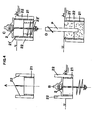
- Figure 1 shows a lateral view of a device for perforating drills comprising an expansion headpiece, a pusher and a finned tube.
- FIGS 2 and 3 show the variants of the device comprising, respectively, the sole expansion headpiece and the sole pusher apparatus in the following stages:
- Figure 4 shows the device comprising the sole reinforcement tube provided with vertical tongues projecting from said tube, in the following stages:
- the present invention concerns a device that may be applied to perforating drills for the execution of foundation holes and the insertion and stabilization of reinforcement tubes, comprising:
Landscapes
- Engineering & Computer Science (AREA)
- Mining & Mineral Resources (AREA)
- Life Sciences & Earth Sciences (AREA)
- Geology (AREA)
- General Life Sciences & Earth Sciences (AREA)
- Environmental & Geological Engineering (AREA)
- Fluid Mechanics (AREA)
- Physics & Mathematics (AREA)
- Geochemistry & Mineralogy (AREA)
- Mechanical Engineering (AREA)
- Paleontology (AREA)
- Civil Engineering (AREA)
- General Engineering & Computer Science (AREA)
- Structural Engineering (AREA)
- Earth Drilling (AREA)
- Placing Or Removing Of Piles Or Sheet Piles, Or Accessories Thereof (AREA)
Abstract
A device that may be applied to perforating drills comprising an expansion headpiece (1) with a determined rotation sense and retraction by motion inversion, that will perform holes of a diameter adapted to the reinforcement tube (of steel, cement or other), a pusher (11) having the function of causing the penetration of the reinforcement tube or the hooking simultaneously to the drilling of the hole, which will therefore be reinforced in one single stage, and a reinforcement tube (21), provided with a series of tongues (22), outwardly fixed, for stabilizing the foundation relating to flexion and torsion and assure the structural connection between the different stages of said tube. Each single component element of the device may be applied to perforating drills or in connection with one or two of the other elements, according to the requests.
Description
- The present invention concerns a device that may be applied to perforating drills for the drilling of foundation holes and the insertion and stabilization of reinforcement tubes of steel, cement and other materials.
- It is already well known that the drilling of holes in the earth oftenly shows the problem of the sinking thereof, that oftenly may take place due to incoherence of the ground or to loads situated nearby. In these cases it is not possible to use traditional drills and it is necessary to use shovel excavators with the performing of greater holes, so that the walls thereof may be reinforced for obtaining the desired dimensions.
- The main inconveniences of this system are:
- - an excavation greater than really necessary;
- - the need of greater space all around;
- - the difficulty of performing the excavation in proximity of _already existing buildings;
- - the need of using molds or similar in case of sinking gounds;
- - the use of more material;
- - the use of more machines;
- - the difficulty of recovering the interred reinforcement;
- - due to all above mentioned, the need of different working stages and therefore more time and higher costs.
- It is the aim of the present invention to rationalize in the best way possible the performance of reinforced holes in the ground, so that the same may be quickly performed in one single stage, thus eliminating all above mentioned inconveniences.
- The aim is reached by means of the device according to the present invention that may be applied to the perforating drills, comprising an expansion headpiece with a determined rotation sense and retraction by motion inversion, that will perform holes of a diameter adapted to the reinforcement tube, a pusher superiorly applied to said drill and a reinforcement tube provided with a series of vertical tongues projecting from said tube.
- The advantages obtained according to the aim set forth by the present invention, are the following:
- - small drilling spaces;
- - the possibility of performing the hole also nearby a building without causing damages;
- - the elimination of the use of molds and similar;
- - the use of one single machine;
- - the shortening of working times and saving of materials with an expense reduction;
- - the posisbility of recovering the interred reinforcement;
- - an extremely simple process, quick and little expensive, with the consequence of the possible ampliance of the utilization field thereof to any kind of ground and application.
- The present invention will be described in detail hereinbelow relating to the enclosed drawings showing some preferred embodiments thereof.
- Figure 1 shows a lateral view of a device for perforating drills comprising an expansion headpiece, a pusher and a finned tube.
- Figures 2 and 3 show the variants of the device comprising, respectively, the sole expansion headpiece and the sole pusher apparatus in the following stages:
- A - lateral view and plant in drilling position;
- B - perforation: start;
- C - perforation: introduction of first tube;
- D - extraction of the drill;
- E - mounting of the second and following tubes;
- F - perforation: introduction of the second and following tubes.
- Figure 4 shows the device comprising the sole reinforcement tube provided with vertical tongues projecting from said tube, in the following stages:
- A - lateral view of the tube with the tongues in penetration position;
- B - introduction of the first tube;
- C - superimposition of the second and following tubes;
- D - introduction of a pile.
- The present invention concerns a device that may be applied to perforating drills for the execution of foundation holes and the insertion and stabilization of reinforcement tubes, comprising:
- - an expansion headpiece 1 provided with one or
more expansion blade 3 which, with the rotation in the sense ofdrills 2 for perforation 4 and in contact with the ground, spread apart in a position 5 and therefore enlargen the hole adapting the same to the outer diameter of the reinforcement tube that is to be introduced. The extraction of the drill then takes place following to the rotation in a sense 6 contrary to the one of perforation, whereby the expansion blades are situated in aposition 7 thus allowing the passing of the drill through the inner diameter of the tube; - - a
pusher apparatus 11, placed upwardly to saiddrill 2, fixed to the non-rotating part thereof so that, when the drill is lowered and the pusher resting on the tube, the same will be downwardly pushed, introducing or forcing it into the provided hole according to the diameter of the same being greater, equal or smaller than the one of the outer diameter of the tube; - - a
reinforcement tube 21, provided with a series ofvertical tongues 22, extending from said tube so as to guide the followingtube 21' and to realize a connection between said tubes. - The functioning and working of the device according to the present invention may be described according to the single stages exemplified in the enclosed drawings:
- Figure 2 B - perforation: start. Tube 21 is placed on the ground and drill 2 with
blades 3 retracted inposition 7 is introduced therein until touching the ground; - C - perforation: introduction of the first tube. At the contact with the ground and rotating the drill as shown with 4,
blades 3 are brought in position 5 enlarging the hole to the desired diameter, so thattube 21, pushed by the own mass or by thepusher apparatus 11, penetrates the ground delimiting the hole and, if necessary, contains the sinkings in any case caused; - D - extraction of the drill: once the
first tube 21 has been completely interred, the rotation sense of the drill is inverted as in position 6, whereby the blades are brought inposition 7 and it is therefore possible to extract the drill without causing any damage to the tube; - E - mounting of the second and following tubes: once the second (and in the same way all the follow- ' ing)
tube 21' has been positioned on the first one, the above described sequence will be repeated and if necessary the drill will be extended. -
- Figure 3 A - the
pusher 11 is placed upwardly to drill 2; - B - perforation: start. The
first tube 21 will be placed on the ground and thedrill 2 will be introduced-therein; - C - perforation: introduction of the first tube: the drill starts perforating and while lowering brings the
pusher 11 at contact with the tube, causing the forced penetration thereof in the ground; - D - extraction of the drill: once the
first tube 21 is completely interred,drill 2 will be extracted; - E - mounting of the second and the following tubes: once the second (and in the same way all the following)
tube 21' has been placed on the first one, above described sequence will be repeated, providing, if necessary, to the extension of the drill. -
- Figure 4 A - the
tube 21 is ready to be placed on the ground, the projection oftongues 22 being upwardly positioned; - B - introduction of the first tube: the
tube 21 will be introduced contemporarily to the execution of the hole; - C - superimposition of the second and following tubes: the
second tube 21' (and in the same way all the following) will be placed on the first one with the tongues 22' offset and will be embraced bytongues 22 of the precedingtube 21, so as to obtain a good connection between the two tubes. The last tube will be inserted with the tongues placed downwardly, eliminating all superficial projection and further improving the connection between the last foundation stages; - D - introduction-of the piles: once the necessary stages have been performed, pile P may be inserted and fixed by upfilling with sand or other material from the foundation.
- It is evident that the elements making up the device according to the present invention may be simultaneously applied so as to perfection the functioning of the perforating drills, but they will be equally effective if working single, one by one, or variously coupled.
Claims (6)
1. A device that may be applied to perforating drills for the drilling of foundation holes and the insertion and stabilization of reinforcement tubes, characterized in the making up elements:
- an expansion headpiece (1) provided with one or more expansion blades (3) which, with the rotation of drill (2) in the perforation sense (4) and at the contact with the ground, spread apart in a position (5) and therefore enlargen the hole adapting the same to the outer diameter of the reinforcement tube to be inserted; the extraction of the drill takes place due to the rotation in a sense (6) contrary to the one of perforation, whereby the expansion blades are brought in a position (7) thus allowing the passage of the drill through the inner-diameter of the tube;
- a pusher apparatus (11), placed upwardly to said drill (2), fixed to the non-rotating part thereof so that, when the drill is lowered and the pusher resting on the tube, the same will be downwardly pushed, introducing or forcing it into the provided hole according to the diameter of the same being greater, equal or smaller than the one of the outer diameter of the tube;
- a reinforcement tube (21), provided with a series of vertical tongues (22), extending from said tube so as to guide the following tube (21') and to realize a connection between said tubes.
2. A device according to claim 1, characterized in that the expansion headpiece (1) is provided with blades (3) hinged thereto in such a way that when the drill rotates in the contrary sense the same will retract so as to allow the extraction of the drill through the reinforcement.
3. A device according to claim 1, characterized in that tube (21), pushed by pusher apparatus (11), penetrates the ground delimiting the hole and/or limiting the sinking thereof.
4.-A device according to claim 1, characterized in that the second tube (21') (and in the same way all the following) will be superimposed to the first one with the tongues (22') thereof offset, and will be embraced by tongues (22) of preceding tube (21), so that a good connection between the two tubes may be obtained.
5. A device according to claims 1 and 4, characterized in that the last tube (21') will be inserted with the tongues thereof placed downwardly, thus eliminating any surface projection and further improving the connection between the last stages of the foundation.
6. A device according to any of the precedent claims, characterized in that elements (1, 11 and 21) may be variously coupled according to the requests.
Applications Claiming Priority (2)
| Application Number | Priority Date | Filing Date | Title |
|---|---|---|---|
| IT48646/85A IT1200133B (en) | 1985-10-08 | 1985-10-08 | DEVICE APPLICABLE TO PERFORATING DRILLS FOR THE IMPLEMENTATION OF THE FOUNDATION HOLES, AND THE INSERTION AND STABILIZATION OF THE REINFORCEMENT PIPES |
| IT4864685 | 1985-10-08 |
Publications (2)
| Publication Number | Publication Date |
|---|---|
| EP0217995A2 true EP0217995A2 (en) | 1987-04-15 |
| EP0217995A3 EP0217995A3 (en) | 1988-10-19 |
Family
ID=11267827
Family Applications (1)
| Application Number | Title | Priority Date | Filing Date |
|---|---|---|---|
| EP85830279A Withdrawn EP0217995A3 (en) | 1985-10-08 | 1985-11-12 | A device that may be applied to perforating drills for the drilling of foundation holes,and the insertion and stabilization of reinforcement tubes |
Country Status (3)
| Country | Link |
|---|---|
| EP (1) | EP0217995A3 (en) |
| AU (1) | AU6076986A (en) |
| IT (1) | IT1200133B (en) |
Cited By (3)
| Publication number | Priority date | Publication date | Assignee | Title |
|---|---|---|---|---|
| WO1990004082A2 (en) * | 1988-10-05 | 1990-04-19 | Sekisui Kagaku Kogyo Kabushiki Kaisha | An underground pipe for a thrust boring method and a connecting construction of the underground pipe for the same |
| EP0962596A1 (en) * | 1998-05-16 | 1999-12-08 | Liberty Offshore Ltd. | Pile and method for installing same |
| EP2319991A3 (en) * | 2002-04-04 | 2012-08-22 | Gebr. van Leeuwen Harmelen B.V. | Method and system for placing at least one foundation element in the ground |
Citations (7)
| Publication number | Priority date | Publication date | Assignee | Title |
|---|---|---|---|---|
| US3077235A (en) * | 1960-08-03 | 1963-02-12 | Salem Tool Co | Collapsible mining head |
| US3779025A (en) * | 1971-10-07 | 1973-12-18 | Raymond Int Inc | Pile installation |
| DE2422489A1 (en) * | 1974-05-09 | 1975-11-20 | Takechi Komusho Kk | Earth borer with drill shaft and screw shaped cutting blade - shaft has hub with stops for rotary blades pivot fitted to hub |
| US4010966A (en) * | 1976-03-18 | 1977-03-08 | Vanden Bosch Paul G | Pipe coupler |
| US4258788A (en) * | 1978-07-21 | 1981-03-31 | Westbay Instruments Ltd. | CPI Casing |
| AT363044B (en) * | 1977-08-02 | 1981-07-10 | Leffer Stahl & App | DEVICE FOR DEPOSITING A PIPED DEEP HOLE FOR PRODUCING A PIPED FOUNDATION |
| US4494613A (en) * | 1982-03-11 | 1985-01-22 | Kabushiki Kaisha Komatsu Seisakusho | Method and apparatus for driving hollow piles into the ground |
-
1985
- 1985-10-08 IT IT48646/85A patent/IT1200133B/en active
- 1985-11-12 EP EP85830279A patent/EP0217995A3/en not_active Withdrawn
-
1986
- 1986-07-31 AU AU60769/86A patent/AU6076986A/en not_active Abandoned
Patent Citations (7)
| Publication number | Priority date | Publication date | Assignee | Title |
|---|---|---|---|---|
| US3077235A (en) * | 1960-08-03 | 1963-02-12 | Salem Tool Co | Collapsible mining head |
| US3779025A (en) * | 1971-10-07 | 1973-12-18 | Raymond Int Inc | Pile installation |
| DE2422489A1 (en) * | 1974-05-09 | 1975-11-20 | Takechi Komusho Kk | Earth borer with drill shaft and screw shaped cutting blade - shaft has hub with stops for rotary blades pivot fitted to hub |
| US4010966A (en) * | 1976-03-18 | 1977-03-08 | Vanden Bosch Paul G | Pipe coupler |
| AT363044B (en) * | 1977-08-02 | 1981-07-10 | Leffer Stahl & App | DEVICE FOR DEPOSITING A PIPED DEEP HOLE FOR PRODUCING A PIPED FOUNDATION |
| US4258788A (en) * | 1978-07-21 | 1981-03-31 | Westbay Instruments Ltd. | CPI Casing |
| US4494613A (en) * | 1982-03-11 | 1985-01-22 | Kabushiki Kaisha Komatsu Seisakusho | Method and apparatus for driving hollow piles into the ground |
Cited By (9)
| Publication number | Priority date | Publication date | Assignee | Title |
|---|---|---|---|---|
| WO1990004082A2 (en) * | 1988-10-05 | 1990-04-19 | Sekisui Kagaku Kogyo Kabushiki Kaisha | An underground pipe for a thrust boring method and a connecting construction of the underground pipe for the same |
| WO1990004082A3 (en) * | 1988-10-05 | 1990-06-14 | Seikisui Chemical Co Ltd | An underground pipe for a thrust boring method and a connecting construction of the underground pipe for the same |
| US5104263A (en) * | 1988-10-05 | 1992-04-14 | Sekisui Kagaku Kogyo Kabushiki Kaisha | Underground pipe for a thrust boring method and a connecting construction of the underground pipe for the same |
| EP0962596A1 (en) * | 1998-05-16 | 1999-12-08 | Liberty Offshore Ltd. | Pile and method for installing same |
| US6368021B1 (en) | 1998-05-16 | 2002-04-09 | Liberty Offshore, Ltd. | Pile and method for installing same |
| GB2364728B (en) * | 1998-05-16 | 2002-12-04 | Duncan Cuthill | Method of and apparatus for installing a pile underwater to create a mooring anchorage |
| US6536993B2 (en) | 1998-05-16 | 2003-03-25 | Liberty Offshore, Ltd. | Pile and method for installing same |
| EP2319991A3 (en) * | 2002-04-04 | 2012-08-22 | Gebr. van Leeuwen Harmelen B.V. | Method and system for placing at least one foundation element in the ground |
| EP2319992A3 (en) * | 2002-04-04 | 2012-08-22 | Gebr. van Leeuwen Harmelen B.V. | Method and system for placing at least one foundation element in the ground |
Also Published As
| Publication number | Publication date |
|---|---|
| IT8548646A0 (en) | 1985-10-08 |
| EP0217995A3 (en) | 1988-10-19 |
| AU6076986A (en) | 1987-04-09 |
| IT1200133B (en) | 1989-01-05 |
Similar Documents
| Publication | Publication Date | Title |
|---|---|---|
| US3391544A (en) | Means and method of forming concrete piles | |
| US5007770A (en) | Method and apparatus for constructing a subsurface retaining wall | |
| EP0217995A2 (en) | A device that may be applied to perforating drills for the drilling of foundation holes,and the insertion and stabilization of reinforcement tubes | |
| KR102092514B1 (en) | Ground drilling method for foundation reinforcement | |
| JPH07145616A (en) | Cast-in-place concrete piling method | |
| EP0413422A1 (en) | Foundation construction method | |
| JPS566822A (en) | Base pile making method | |
| JP2779389B2 (en) | Rotary press-in device for steel pipe piles for settlement settlement | |
| GB2157750A (en) | Improvements relating to cast-in-situ concrete pile construction | |
| JPH04302693A (en) | Excavating engineering method | |
| JP2575088B2 (en) | Improvement method and equipment of foundation ground | |
| JPH05222723A (en) | Forming method for foundation pile | |
| JP2832481B2 (en) | Drilling rig for hole for concrete pile installation | |
| RU2117106C1 (en) | Method for erection of pile or post in loose or unstable ground | |
| US1593445A (en) | Method of installing mushroom piling | |
| EP0437262A1 (en) | Method for preventive consolidation of the soil for underground minings | |
| JP2514596B2 (en) | Ground drilling equipment | |
| JPH07116707B2 (en) | Drilling method for foundation ground and its equipment. | |
| JPH0759873B2 (en) | Pile hole excavation method and device | |
| JPH1037650A (en) | Drilling device for foundation ground | |
| JPS6037249B2 (en) | How to build large long foundation piles | |
| JP2610555B2 (en) | Drilling method for foundation ground and its drilling equipment | |
| SU966167A1 (en) | Method of strengthening foundation on constructed building | |
| JPS63184614A (en) | Method and apparatus for penetration of steel tubular pile | |
| JPH01187225A (en) | Centering base frame and casing or steel tubular pile penetrating work therewith |
Legal Events
| Date | Code | Title | Description |
|---|---|---|---|
| PUAI | Public reference made under article 153(3) epc to a published international application that has entered the european phase |
Free format text: ORIGINAL CODE: 0009012 |
|
| AK | Designated contracting states |
Kind code of ref document: A2 Designated state(s): AT BE CH DE FR GB LI NL SE |
|
| PUAL | Search report despatched |
Free format text: ORIGINAL CODE: 0009013 |
|
| AK | Designated contracting states |
Kind code of ref document: A3 Designated state(s): AT BE CH DE FR GB LI NL SE |
|
| STAA | Information on the status of an ep patent application or granted ep patent |
Free format text: STATUS: THE APPLICATION IS DEEMED TO BE WITHDRAWN |
|
| 18D | Application deemed to be withdrawn |
Effective date: 19890420 |
|
| RIN1 | Information on inventor provided before grant (corrected) |
Inventor name: PACCAGNELLA, DANILO |