EP0216488B1 - Digital signal processor - Google Patents
Digital signal processor Download PDFInfo
- Publication number
- EP0216488B1 EP0216488B1 EP86306271A EP86306271A EP0216488B1 EP 0216488 B1 EP0216488 B1 EP 0216488B1 EP 86306271 A EP86306271 A EP 86306271A EP 86306271 A EP86306271 A EP 86306271A EP 0216488 B1 EP0216488 B1 EP 0216488B1
- Authority
- EP
- European Patent Office
- Prior art keywords
- signals
- digital
- control
- digital signal
- tone
- Prior art date
- Legal status (The legal status is an assumption and is not a legal conclusion. Google has not performed a legal analysis and makes no representation as to the accuracy of the status listed.)
- Expired
Links
- 238000012545 processing Methods 0.000 claims abstract description 22
- 230000002457 bidirectional effect Effects 0.000 claims abstract description 10
- 238000000034 method Methods 0.000 claims description 5
- 230000009977 dual effect Effects 0.000 claims description 4
- 230000008569 process Effects 0.000 claims description 4
- 230000004044 response Effects 0.000 claims description 4
- 239000004020 conductor Substances 0.000 claims description 3
- 238000001514 detection method Methods 0.000 claims description 3
- 230000006835 compression Effects 0.000 abstract description 4
- 238000007906 compression Methods 0.000 abstract description 4
- 238000013461 design Methods 0.000 abstract description 3
- 238000001914 filtration Methods 0.000 abstract description 2
- 238000012937 correction Methods 0.000 description 11
- 101150004219 MCR1 gene Proteins 0.000 description 7
- 101100206347 Schizosaccharomyces pombe (strain 972 / ATCC 24843) pmh1 gene Proteins 0.000 description 7
- 238000006243 chemical reaction Methods 0.000 description 6
- 230000005236 sound signal Effects 0.000 description 5
- 238000010586 diagram Methods 0.000 description 4
- 238000005070 sampling Methods 0.000 description 4
- 102000003979 Mineralocorticoid Receptors Human genes 0.000 description 3
- 108090000375 Mineralocorticoid Receptors Proteins 0.000 description 3
- 230000008901 benefit Effects 0.000 description 3
- 230000005540 biological transmission Effects 0.000 description 3
- 238000006452 multicomponent reaction Methods 0.000 description 3
- 102100027206 CD2 antigen cytoplasmic tail-binding protein 2 Human genes 0.000 description 2
- 101000914505 Homo sapiens CD2 antigen cytoplasmic tail-binding protein 2 Proteins 0.000 description 2
- 101000922137 Homo sapiens Peripheral plasma membrane protein CASK Proteins 0.000 description 2
- 102100031166 Peripheral plasma membrane protein CASK Human genes 0.000 description 2
- 238000011084 recovery Methods 0.000 description 2
- YREOLPGEVLLKMB-UHFFFAOYSA-N 3-methylpyridin-1-ium-2-amine bromide hydrate Chemical compound O.[Br-].Cc1ccc[nH+]c1N YREOLPGEVLLKMB-UHFFFAOYSA-N 0.000 description 1
- 101150080661 Ear1 gene Proteins 0.000 description 1
- 101000633516 Homo sapiens Nuclear receptor subfamily 2 group F member 6 Proteins 0.000 description 1
- 101150081376 NR1D1 gene Proteins 0.000 description 1
- 102100023170 Nuclear receptor subfamily 1 group D member 1 Human genes 0.000 description 1
- 102100029528 Nuclear receptor subfamily 2 group F member 6 Human genes 0.000 description 1
- 230000004913 activation Effects 0.000 description 1
- 238000001816 cooling Methods 0.000 description 1
- 230000009849 deactivation Effects 0.000 description 1
- 238000012217 deletion Methods 0.000 description 1
- 230000037430 deletion Effects 0.000 description 1
- 238000005516 engineering process Methods 0.000 description 1
- 238000003780 insertion Methods 0.000 description 1
- 230000037431 insertion Effects 0.000 description 1
- 238000002955 isolation Methods 0.000 description 1
- 230000004048 modification Effects 0.000 description 1
- 238000012986 modification Methods 0.000 description 1
- 230000002093 peripheral effect Effects 0.000 description 1
- 230000035755 proliferation Effects 0.000 description 1
- 230000011664 signaling Effects 0.000 description 1
Images


Classifications
-
- G—PHYSICS
- G06—COMPUTING; CALCULATING OR COUNTING
- G06F—ELECTRIC DIGITAL DATA PROCESSING
- G06F15/00—Digital computers in general; Data processing equipment in general
- G06F15/76—Architectures of general purpose stored program computers
- G06F15/78—Architectures of general purpose stored program computers comprising a single central processing unit
- G06F15/7828—Architectures of general purpose stored program computers comprising a single central processing unit without memory
- G06F15/7832—Architectures of general purpose stored program computers comprising a single central processing unit without memory on one IC chip (single chip microprocessors)
-
- H—ELECTRICITY
- H04—ELECTRIC COMMUNICATION TECHNIQUE
- H04M—TELEPHONIC COMMUNICATION
- H04M1/00—Substation equipment, e.g. for use by subscribers
- H04M1/253—Telephone sets using digital voice transmission
-
- H—ELECTRICITY
- H04—ELECTRIC COMMUNICATION TECHNIQUE
- H04Q—SELECTING
- H04Q1/00—Details of selecting apparatus or arrangements
- H04Q1/18—Electrical details
- H04Q1/30—Signalling arrangements; Manipulation of signalling currents
- H04Q1/44—Signalling arrangements; Manipulation of signalling currents using alternate current
- H04Q1/444—Signalling arrangements; Manipulation of signalling currents using alternate current with voice-band signalling frequencies
- H04Q1/45—Signalling arrangements; Manipulation of signalling currents using alternate current with voice-band signalling frequencies using multi-frequency signalling
- H04Q1/457—Signalling arrangements; Manipulation of signalling currents using alternate current with voice-band signalling frequencies using multi-frequency signalling with conversion of multifrequency signals into digital signals
- H04Q1/4575—Signalling arrangements; Manipulation of signalling currents using alternate current with voice-band signalling frequencies using multi-frequency signalling with conversion of multifrequency signals into digital signals which are transmitted in digital form
-
- H—ELECTRICITY
- H04—ELECTRIC COMMUNICATION TECHNIQUE
- H04Q—SELECTING
- H04Q11/00—Selecting arrangements for multiplex systems
- H04Q11/04—Selecting arrangements for multiplex systems for time-division multiplexing
- H04Q11/0428—Integrated services digital network, i.e. systems for transmission of different types of digitised signals, e.g. speech, data, telecentral, television signals
-
- H—ELECTRICITY
- H04—ELECTRIC COMMUNICATION TECHNIQUE
- H04Q—SELECTING
- H04Q2213/00—Indexing scheme relating to selecting arrangements in general and for multiplex systems
- H04Q2213/13034—A/D conversion, code compression/expansion
-
- H—ELECTRICITY
- H04—ELECTRIC COMMUNICATION TECHNIQUE
- H04Q—SELECTING
- H04Q2213/00—Indexing scheme relating to selecting arrangements in general and for multiplex systems
- H04Q2213/13103—Memory
-
- H—ELECTRICITY
- H04—ELECTRIC COMMUNICATION TECHNIQUE
- H04Q—SELECTING
- H04Q2213/00—Indexing scheme relating to selecting arrangements in general and for multiplex systems
- H04Q2213/13106—Microprocessor, CPU
-
- H—ELECTRICITY
- H04—ELECTRIC COMMUNICATION TECHNIQUE
- H04Q—SELECTING
- H04Q2213/00—Indexing scheme relating to selecting arrangements in general and for multiplex systems
- H04Q2213/13107—Control equipment for a part of the connection, distributed control, co-processing
-
- H—ELECTRICITY
- H04—ELECTRIC COMMUNICATION TECHNIQUE
- H04Q—SELECTING
- H04Q2213/00—Indexing scheme relating to selecting arrangements in general and for multiplex systems
- H04Q2213/1319—Amplifier, attenuation circuit, echo suppressor
-
- H—ELECTRICITY
- H04—ELECTRIC COMMUNICATION TECHNIQUE
- H04Q—SELECTING
- H04Q2213/00—Indexing scheme relating to selecting arrangements in general and for multiplex systems
- H04Q2213/13216—Code signals, frame structure
-
- H—ELECTRICITY
- H04—ELECTRIC COMMUNICATION TECHNIQUE
- H04Q—SELECTING
- H04Q2213/00—Indexing scheme relating to selecting arrangements in general and for multiplex systems
- H04Q2213/13292—Time division multiplexing, TDM
-
- H—ELECTRICITY
- H04—ELECTRIC COMMUNICATION TECHNIQUE
- H04Q—SELECTING
- H04Q2213/00—Indexing scheme relating to selecting arrangements in general and for multiplex systems
- H04Q2213/1332—Logic circuits
-
- H—ELECTRICITY
- H04—ELECTRIC COMMUNICATION TECHNIQUE
- H04Q—SELECTING
- H04Q2213/00—Indexing scheme relating to selecting arrangements in general and for multiplex systems
- H04Q2213/13396—Signaling in general, in-band signalling
-
- H—ELECTRICITY
- H04—ELECTRIC COMMUNICATION TECHNIQUE
- H04Q—SELECTING
- H04Q2213/00—Indexing scheme relating to selecting arrangements in general and for multiplex systems
- H04Q2213/13405—Dual frequency signaling, DTMF
Definitions
- This invention relates to telecommunication equipment and, more particularly, to a general-purpose digital processor which performs a variety of signal processing functions for both the receive and transmit sides of an audio processor section of a digital subscriber controller.
- the prior art has employed discrete and/or expensive custom circuitry which lacks the flexibility to meet changing subscriber needs. Furthermore such circuitry encourages proliferation of incompatible implementations which vary in physical, electrical and line protocol characteristics. Additionally, the prior art interfaces occupy large amounts of space, have high power consumption thereby generating considerable heat which requires cooling apparatus and lack the reliability of monolithic integrated circuitry.
- the audio signal processing circuitry of prior art interfaces was complex and typically required two separate digital signal processors, one for the transmit section another for the receive section.
- Representative of such apparatus is that disclosed in the patent application document WO-A-8000753 entitled "Interpolative Analog-to-Digital Converter for Subscriber Line Audio Processing Circuit Apparatus" filed June 18, 1980 on behalf of R.J. Apfel, A.G. Eriksson and L.T.E. Svensson, involving considerable custom-designed logic circuitry in the signal processing and control sections.
- prior art apparatus was typically hybrid digital/analog such as that disclosed in U S -A- 4,061,886.
- a digital-to-analog (D/A) ladder network converts digitally coded signals to analog sine waves and an analog operational amplifier is used to combine the sinusoidal waveforms to provide a dual-tone output signal.
- D/A ladder circuitry unnecessarily complicates the disclosed apparatus and introduces undesirable imperfecrtions in the signals generated.
- the waveforms generated are selectable from only a limited hard-wired number of frequencies and amplitudes and cannot be changed without extensive modification of the circuitry.
- the hybrid apparatus requires circuitry dedicated to the generation of tones, a relatively simple operation for a digital microprocessor to perform.
- Such digital processors are usually already present within telecommunication equipment and could be used for tone generation without the need for elaborate dedicated circuitry, provided an all-digital technique were available with which to generate dual-tone multi-frequency waveforms with the requisite accuracy.
- a digital signal processor is described in ELECTRONICS INTERNATIONAL, vol.53, No.26, 4th December 1980, pages 79-80, New York, US; R.P. CAPECE "digital N-mos chip handles analog signals at record 200 kHz", which includes two busses connected to an ALU and external devices.
- a microprocessor with two parallel busses is outlined in ELECTRONICS, vol 53, No.22, October 1980, pages 75-76, New York, US; C. COHEN: "The power is with a new 16-bit SOS microprocessor".
- the processor includes an input/output of double the width of the two internal parallel busses, which can be used in both time and space multiplexed modes.
- An all-digital signal processor (DSP) is hereindisclosed which performs pulse code modulation (PCM) coding and decoding (CODEC) filter operations for both received and transmitted signals, among other functions.
- the DSP is particularly suited for use in the main audio processor (MAP) of an integrated services digital network (ISDN) terminal equipment controller which interfaces with an external microprocessor.
- MAP main audio processor
- ISDN integrated services digital network
- a user can access various programmable registers via the microprocessor to specify parameters used in the execution of programs by the DSP of the instant invention.
- the DSP contains two 19-bit wide data busses for commmunication between its various elements, which include a random access memory (RAM), an arithmetic-logic unit (ALU), and an interface to a receive-side analog-to-digital (A/D) converter and a transmit-side digital-to-analog (D/A) converter.
- a programmed logic array (PLA) executes microcode which controls the processing of signals by the ALU section.
- a variety of other operations can be performed under control of the PLA such as generation of dual-tone multi-frequency (DTMF) signals commonly used in telecommunications.
- DTMF dual-tone multi-frequency
- the architecture of the DSP provides a number of user-accessible registers for the storage of parameters and coefficients used in the generation of the DTMF signals, in the CODEC filtering, and in the compression and expansion of signals.
- a single general-purpose DSP of the present invention serves to process signals on both the receive- and transmit-sides and as it is of a purely digital nature requires little support circuitry dedicated to particular functions.
- the design of the general-purpose DSP follows a structured methodolgy which avoids special-case circuit solutions and critical timing paths.
- the main audio processor (MAP) 160 of the present invention is shown in an exemplary application within a digital subscriber controller (DSC) 34 consisting of seven functional blocks, as illustrated in Fig. 1.
- DSC digital subscriber controller
- the DSC provides digital subscriber access to a telephone network.
- the DSC is compatible with the CCITT I-series recommendations at reference point "S". Accordingly, the user of the DSC according to the present invention may utilize it in terminal equipment (TE) which conforms to international standards.
- TE terminal equipment
- DSC 34 provides a 192 kilo-bit per second (kbs) full-duplex digital path for bit-streams received via an isolation transformer (not shown) on a four-wire "S" interface at terminals LIN1 and LIN2, and transmitted on the four-wire interface from terminals LOUT1 and LOUT2.
- the DSC separates the received bit-stream into B1 and B2 channels (each 64 kbs), and a D channel (16 kbs).
- the B channels are routed to different ones of the functional blocks illustrated in Fig. 1 under user control via the multiplexer 170.
- the D-channel is partially processed at the Level 2 in the DSC 34 and passed via a microprocessor interface (MPI) 100 to a programmable microprocessor (MPC, not shown) for additional processing.
- MPI microprocessor interface
- MPC programmable microprocessor
- the DSC 34 includes a line interface unit (LIU) 110, connected to the terminals LIN1 and LIN2, which contains a receiver section 120 and a transmitter section 130.
- the receiver section 120 consists of a receiver filter, a digital phase-lock loop (DPLL) for clock recovery, two slicers for detecting high marks and low marks of the incoming bit-stream frames, and a frame recovery circuit for frame synchronization.
- LIU line interface unit
- DPLL digital phase-lock loop
- Receiver 120 converts the incoming pseudo-ternary encoded bit stream into binary before conducting it to the other blocks of the DSC 34, illustrated in Fig. 1, via a bus 140.
- the receiver 110 also performs D-channel access protocol to resolve potential contention when the DSC 34 is operating in the "point-to-multipoint" configuration.
- the transmitter section 130 consists of a binary-to-pseudo-ternary encoder and a line driver which receives signals on the bus 140 and causes an outgoing bit stream to be generated therefrom at the LOUT1 and LOUT2 terminals of the DSC 34.
- This outgoing bit stream is as specified in the CCITT recommendations for the "S" interface.
- the LIU 110 conform to the CCITT recommendations for level 1 activation and deactivation on the "S" interface. This is achieved by transmitting, and decoding, the standard CCITT "Info" signals.
- the LIU 110 is also responsive to a signal on a hook switch (HSW) terminal of the DSC 34.
- the HSW terminal receives a signal indicative of the off-hook or on-hook condition of a handset connected to the DSC.
- the DSC 34 also includes a data link controller (DLC) 150 connected to the bus 140 which partially processes the 16 kbs D-channel received via the LIU 110.
- the partial processing of the layer 2 of the protocol includes flag detection and generation, zero deletion and insertion, frame check sequence processing for error detection, and some addressing capability.
- the external microprocessor initializes the DLC 150 and performs higher level protocol processing.
- D-channel data is conducted from the LIU 110 to the DLC 150, via bus 140, and then to the microprocessor interface (MPI) 100 for transmission from a set of eight data terminals (D0, D1, D2, D3, D4, D5, D6, and D7) of the DSC 34 to the external microprocessor.
- MPI microprocessor interface
- D-channel data is conducted from MPI 100 to the LIU 110 via DLC 150 for transmission on the D-channel over the "S" interface.
- a main audio processor (MAP) 160 contained within the DSC 34 performs digital-to-analog (D/A) conversion within a D/A section 162 and analog-to-digital (A/D) conversion within an A/D section 164 and digital processing of the signals present in the DSC 34 in a digital signal processing (DSP) section 166.
- Analog audio signals can be applied to MAP portion of the DSC 34 at two general analog inputs (AINA, AINB, AGND) and analog voice signals are generated by the MAP Portion at earphone terminals (EAR[1] and EAR[2]) and at loudspeaker terminals (LS1 and LS2).
- the MAP 160 of the instant invention contains three user-programmable features which are accessible to the user at the MAP terminals.
- the first is a multi-tone generator section of the present invention; the second is a pair of attenuation distortion correction filters, and the third is a pair of gain adjustment filters.
- the MAP 160 transmits and receives digital signals on the bus 140 carrying digital representations of audio signals received at the AINA, or AINB terminal or to be generated at the EAR1 and EAR2 terminals or at the LS1 and LS2 terminals, respectively.
- a multiplexer (MUX) 170 portion of the DSC 34 is externally programmable via the external microprocessor and, in response, controls the multiplexed bit-streams on the B1 and B2 channels which are received and transmitted to external peripheral devices from the DSC 34 at a serial-B input (SBIN) terminal of the DSC 34 and a serial-B output (SBOUT) terminal of the DSC 34, respectively.
- the MUX 170 can be programmed to establish a variety of different signal paths via the bus 140 having source and destinations, including: the SBIN terminals, the SBOUT terminal, the MPI 100, the LIU 110, and the MAP 160.
- the D-channel data is routed to the DLC 150 directly from the LIU 110.
- the MUX 170 contains four multiplexer control registers (MCR1, MCR2, MCR3 and MCR4), which can be programmed via the MPI 100 to direct data flow along subscriber selected bidirectional data paths shown functionally in Fig. 1 as bus 140.
- MCR1, MCR2, MCR3 and MCR4 multiplexer control registers
- the MUX 170 can establish those bidirectional paths between the eight MUX logical parts B1, B2, Ba, Bb, Bc, Bd, Be, and Bf, shown in Fig. 2, as controlled by the contents of MCR1, MCR2, and MCR3. These MCRs are externally programmed to connect any two of the eight logical B-channel ports together by writing an appropriate channel code into the corresponding MCR. Each of the MCR1, MCR2, and MCR3 receives a pair of four-bit channel codes, which, in accordance with Table I, below, specifies the logical channel interconnections.
- the bus structure internal to the DSC 34, shown functionally as bus 140 on Fig. 1 is illustrated in Fig. 3. Shown thereon are the B-channel bidirectional data paths B1 and B2, Ba, Bb and Bc, Bd, Be and Bf referred to in section B.1, above, designated 200, 202, 204 and 206, respectively, on Fig. 3. In addition, shown on Fig.
- control busses 208, 210 and 212 which interconnect ports DA[7-0], DB[7-0] and MP1STRT[6-0], respectively of the MPI 100 with the ports DA[7-0], DB[7-0] and MP1STRT[6-0] of the LIU 110, the DLC 150, the receive/transmit filters 166 of MAP 160, and the MUX 170.
- the contents of the MCR1, MCR2, and MCR3 registers determines the particular interconnection implemented on data busses 200, 202, 204 and 206, as described in Section B.1, above, in accordance with Table I.
- the manner in which the user programs the MCR1, MCR2, and MCR3 registers, as well as the other user-accessible registers within the DSC 34 is described in Section C, below.
- an analog-to-digital (A/D) 162 section of MAP 160 is connected to the DSP section 166 of MAP 160 by a bus 214, and a digital-to-analog (D/A) 164 section to the filters 166 by a bus 216.
- a D-channel bidirectional data path 218 interconnects LIU 110 and DLC 150 and a D-channel bidirectional data path 220 interconnects DLC 150 and MPI 100.
- the DSC 34 includes a number of programmable registers and filters which can be accessed via the microprocessor interface (MPI) 100.
- Fig. 4A illustrates the internal structure of the MPI 100, which includes an input/output (I/O) buffer 300, and command register (CR) 302, an interrupt register (IR) 304, D-channel status register (DSR) 306 and D-channel error register (DER) 308.
- the CR 302, IR 304, DSR 306 and DER 308 are user-accessible via the D[0-7] terminals of the DSC 34 and the I/O Buffer 300.
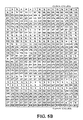
- the CR 302 consists of an eight-bit register as shown in Fig. 48.
- the CR 302 is subdivided into a three-bit (Y2, Y1, Y0) field containing the destination code field (DCF) and a five-bit (Z4, Z3, Z2, Z1, Z0) field containing the operational code field (OCF).
- the "Y" bits of the DCF define which section of the DSC 34 is to be accessed by the user via the MPI 100, in accordance with Table II, below.
- the "Z" bits of the OCF define which Data Register(s) within the section of the DSC 34 specified by the DCF of the eight-bit contents of the command register, in accordance with Table III, below.
- Table III refers to a number of registers which do not reside in the MPI 100 section of the DSC 34.
- the transmit (X), receive (R), gain transmit (GX), gain receive (GER), and side tone gain are programmable filters with user-programmable gains within the receive/transmit filter section 166 of the MAP 160.
- the frequency tone generator registers (FTGR) 1 and 2 are associated with theuser-programmable tone generators within the receive/transmit filter section of the MAP.
- MAP Mode registers (MMR) 1 and 2 are user-programmable registers within the receive/transmit filter section providing user-access to the tone generators and other user-selectable MAP functions.
- the DSC 34 includes the MAP 160 of the present invention, consisting of a transmit section which converts the received analog audio signal to digital signals and a receive section which converts the received digital signals to analog audio signals.
- the MAP 160 contains a number of user-accessible registers which permit MPC control of the signal processing performed within the MAP 160.
- a decimator (D1) 600 which reduces the sampling frequency to 128 KHz.
- the resulting 128 KHz digital signals are applied to a second decimator (D2) 602, which reduces the sampling frequency to 64 KHz.
- D3 receives the 64 KHz generated by decimator 604, and generates therefrom a 32 KHz signal.
- a user-programmable dual tone multi-frequency (DTMF) generator (DT) 604 which can be enabled via a MAP mode register, as described below, is one of three tone generators included in the MAP 160.
- the DTMF generator 604 can be used to generate a signal consisting of one or two tones in which the frequency, amplitude and cadence of the tone is programmable via the MPC.
- the tone(s) can be routed into the 32 KHz signal generated at the output of decimator 603 at a two-way switch 606.
- One pole of the switch 606 is connected to the output of the third decimator 603.
- the second pole of switch 606 is connected to the DTMF generator 604.
- the arm of switch 606 is connected to the fourth decimator 610.
- the signals generated by decimator 603, including the signal from the DTMF generator 604, are conducted to a fourth decimator (D4) 610 which reduces the sampling frequency to 16 KHz.
- a transmit low pass filter (LPX) 612 and high pass filter (HP1, HP2) 614 acting in series on the 16 KHz signal generated by the fourth decimator 610 produce an 8 KHz signal applied to a user-programmable transmit attenuation distortion correction eight-tap FIR filter (X) 616.
- LPX low pass filter
- HP1, HP2 high pass filter
- the transmit correction filter 616 can be programmed to modify the frequency characteristics in the MAP transmit section to compensate for the characteristics of the microphone or other transducer connected to the AINA, AINB and AGND terminals of the DSC 34.
- the filter 616 can also be programmed to add pro- and/or post-emphasis to match other characteristics desired by the user.
- the corrected signals generated by the transmit correction filter 616 are conducted to a user-programmable transmit gain adjustment filter (GX) 618, and therefrom to a compressor (OUT) 620.
- the compressor 620 employs a digital compression algorithm which implements either a Mu-law or an A-law conversion on the linear digital data.
- the resulting compressed signal is conducted to the MUX 170 via signal lines 202. (Fig. 3).
- the transmitted signals are available at the output of the transmit correction filter 616 for introduction into the MAP receive section, as will be described below.
- a MAP control 622 provides access to elements of the MAP 160 via internal bus 624 through the MPI 100, as well as to supply timing and signal processing signals to the elements of MAP 160.
- the filter timing signals produced by MAP control 622 are illustrated in Fig. 5B.
- a total of 512 clock cycles are used by DSP 166 to execute the various transmit-side and receive-side functions shown in Figs. 5A and 5C, below. Each function is allocated the particular sequence of cycles shown in Fig. 5B indicated by the acronym of the function used on Figs. 5A and 5C.
- Fig. 5C illustrates signal flow in the receive section of MAP 160.
- Signals from the MUX 170 are received by an expander 630 which performs a Mu-law, or an A-law-to-linear conversion.
- the resulting linear digital signals are conducted to a receive gain adjustment filter (GR) 632 and therefrom to a summer 634.
- GR receive gain adjustment filter
- a programmable side tone generator (ST) 636 connected to the output of the transmit correction filter 616, permits the transmitted signals to be introduced into the MAP receive section at the summer 634 to which the side tone generator is connected.
- a tone message generator (TM) 638 is also connected to summer 634.
- the output of summer 634 is applied to a second programmable receive gain adjustment filter (GER) 640, the output of which is connected to one pole of a software-controllable switch 642.
- the second pole of the switch 642 is connected to the ouput of a tone ringer generator (TR) 644.
- the signals generated by side tone generator 636 can be used to add a portion of the transmitted signal to the receive channel.
- the signals generated by the tone message generator 638 and the tone ringer generator 644 can be used as ringing tones, busy signals, ringback tones or other call progress tones.
- the arm of switch 642 is connected to a user-programmable receive attenuation distortion correction eight-tap FIR filter (R) 646.
- the resulting corrected 8 KHz signal is conducted to a receiver low pass filter (LPR) 648 and therefrom to a series of four interpolation filters (I1), (I2), (I3) and (I4), 650, 652, 654 and 656 to increase the sampling frequency to 256 KHz.
- LPR receiver low pass filter
- the output from the last interpolation filter 656 is transmitted to the D/A converter 162 (Fig. 1) of MAP 160.
- the filter timing signals shown in Fig. 5B control the execution of the various receive-side functions shown in Fig. 5C as described above in connection with the transmit-side functions.
- the three programmable MAP tone generators 604, 638 and 644 can be programmed with two frequency values and two amplitude values stored in two eight-bit bytes of a frequency tone generator register (FTGR) and two eight-bit bytes and an amplitude tone generator register (ATGR).
- a second MAP mode register (MMR2) is an eight-bit register whose contents enable certain of the tone generators as will now be described.
- the contents of the FTGR correspond to a frequency between 300 and 3000 Hz
- the contents of the ATGR correspond to an amplitude between 0 and -18 db in 2db steps.
- the MAP 160 transmit and receive sections contain the eight sets of user-programmable registers listed in Table IV, below. These registers are enabled or disabled in accordance with the contents of two MAP mode registers (MMR1) and MMR2) as described in Table V, below.
- the user-programmable filter coefficients referred to in the first six rows of Table IV are stored in the MAP coefficient random access memory (RAM) upon reception of data from the MPC via MPI 100. Alternatively, default values are stored in a MAP programmable logic array (PLA). TABLE IV MAP Programmable Registers Register Name Bytes Stored Default Values Transmit Correction Filter (616) Coefficients 16 0 db flat Receive Correction Filter (646) Coefficients 16 0 db flat Transmit Gain Adj.
- an arithmetic logic unit (ALU) 700 with its associated random access memory (RAM) 702 is contained within the digital signal processing (DSP) block 166.
- Data representing signals received from A/D converter 164 or transmitted to D/A converter 162 are temporarily stored within the RAM 702 and digitally processed by the ALU 700.
- a compressor 704 (620 in Fig. 5A) performs the Mu-law or A-law conversion of the digital signals generated by the ALU 700 and the resulting compressed signal is stored in a PCM output register 706 and conducted therefrom to the MUX 170.
- An expander 708 receives the digital signals from MUX 170 via a PCM input register 710 and performs the mu-law or A-law conversion and conducts the resulting linear digital signals to the ALU 700 for signal processing.
- a control section 712 (622 in Fig. 5A) of the DSP block 166 generates control signals to the ALU 700, the data RAM 702, the compressor 704 and the expander 708.
- the control 712 has an associated random access memory (RAM) 714 for storing the user-programmable numerical coefficients used by the ALU 700 during processing of the signals.
- RAM random access memory
- the DSP section 166 of MAP 160 includes the data RAM 702, the PCM output and input registers 706 and 710, control 712, and the coefficient RAM 714 discussed in connection with Fig. 6.
- the ALU 700 section of DSP 166 is shown in greater detail in Fig. 7 as including a pair of bidirectional 19-conductor busses; an A bus 720 and a B bus 722.
- the data RAM 702 is connected to the A and B busses via an output latch 724 and via an input latch 726.
- a register 728 which stores numerical constants is connected to the A bus 720.
- a 19-bit adder/subtractor 730 has an A-side input connected to A bus 720 and a B-side input connected to B bus 722 via a shift register 732.
- Adder/subtractor 730 receives a carry-in (C_IN) signal and an add/subtract (+/-) signal generated by a shift multiplexer 734. Shift multiplexer 734 also generates in parallel a 3-bit shift control signal which is received by the shift register 732. The resulting sum or difference of the 19-bit binary numbers corresponding to the signals received at the A and B input ports to adder/subtractor 730 is generated therein and conducted to a correction multiplexer 736.
- C_IN carry-in
- Shift multiplexer 734 also generates in parallel a 3-bit shift control signal which is received by the shift register 732.
- the resulting sum or difference of the 19-bit binary numbers corresponding to the signals received at the A and B input ports to adder/subtractor 730 is generated therein and conducted to a correction multiplexer 736.
- An overflow detector (O/F DET) 738 also receives the signals corresponding to the binary numbers received by the adder/subtractor 730 as well as a carry-out signals generated by adder/subtractor 730 and produces an overflow signal which is received by correction multiplexer 736 as well as by a tone generator control 740. In this manner ALU 700 performs so-called saturation arithmetic.
- the corrected result of adding or subtracting the values of the A and B inputs to adder/subtractor 730 is generated by the multiplexer 738 and received by an accumulator 742.
- the contents of accumulator 742 is conducted to the B bus 722.
- the corrected result generated by multiplexer 738 is also conducted via a buffer 744 to the A bus 720 and via a latch to the D/A converter 162.
- the A/D converter 164 is connected to the ALU 700 via A bus 720.
- Control 712 receives via MPI 100 and MAP mode registers (MMR1) 750 and (MMR2) 752 the signals generated by the MPC which enable/disable and control the contents of the eight sets of user-programmable registers within the MAP 160. Control signals are generated by control 712 in accordance with the contents of MMR1 750 and MMR2 752 as well as the clock and frame synchronization signals received from OSC 180 which are received by the various elements of the DSP 166 shown in Fig. 7. However, many of the lines conducting these signals are not explicitly shown in Fig. 7 nor are all these signals described herein as generally the nature and distribution of such signals are well-known to those skilled in the art.
- Control 712 generates in parallel a six-bit address which is received by a latch 754 which is decoded by address decoder 756 and the contents at the specified address is accessed in data RAM 702 during data read and write operations.
- a coefficient RAM control 756 generates in response to a signal received from control 712 in parallel a 7-bit address which is received by a latch 758 which is decoded by an address decoder 759 and the contents of the specified address is accessed in coefficient RAM 714.
- Numerical coefficient data is received from MPI 100 and conducted via control 756 and a latch 760 and stored within coefficient RAM 714 at the specified address.
- numerical coefficient data may be read from coefficient RAM 714 at the specified address and conducted in parallel on a 4-bit signal line to the shift multiplexer 734.
- Control 712 may generate in parallel on a 4-bit signal line coefficient data which is conducted to the shift multiplexer 734.
- Tone generator control 740 generates on a pair of 1-bit signal lines signals which are received by the shift multiplexer 734, as will be described below.
- a priority encoder 762 connected to B bus 722 generates in parallel on a 3-bit signal line signals also received by shift multiplexer 734.
- a compression multiplexer 764 is connected to priority encoder 762 and to the B bus 722 and generates a time-division multiplexed signal therefrom which is received by the PCM output register 706.
- the PCM input register 710 is connected to an expansion multiplexer 766 which generates in parallel on a 4-bit signal line signals received by the shift multiplexer 734 and generates in parallel on a 19-bit conductor signals to the B bus 722.
- Register 710 and multiplexer 766 together perform the expander operation labelled 630 in Fig. 5C.
- the shift multiplexer 734 also receives a signal corresponding to a binary ZERO, and in response to a 3-bit shift register control signal generated in parallel by control 712, one of the signals received by the multiplexer 734 is conducted to the adder/subtractor 730 and the shift register 732, in accordance with Table VI, below.
- a tone register 1 768 and a tone register 2 770 receive the user-selected tone coefficient signals generated by the external microprocessor (MPC) via the MPI 100 and these signals are conducted therefrom to the B bus 722.
- MPC external microprocessor
- These registers together with tone generator control 740 perform the DTMF, tone ringer, and tone message generation operations labelled 604, 644 and 638 in Figs. 5A and 5C.
- tone register 1 and 2 are conducted via the B bus 722 and the shift register 732 to the B input part of the adder/subtractor 730 under control of the 3-bit parallel signals generated by the shift multiplexer 734 and received by the shift register 732, in accordance with Table VI, above.
- COEFF variable which will be used in the description of the operation of the DSP 166 shown in Fig. 7, reflects the number of right shifts to be performed by shift register 732 as well as the state of the add/subtract signal received by adder/subtractor 730.
- the COEFF variable represents the 4-bit parallel signals generated by shift multiplexer 734 of which a 3-bit parallel portion is received by the shift register 732 which determines the number of right shifts to be performed thereby and a 1-bit portion is received by the adder/subtractor 730 which determines whether an addition or a subtraction is to be performed thereby.
- the adder/subtractor 730 can select one of the following as a source: the buffer 744, the data RAM output latch 724, or the constants register 728. Selection is performed by the A bus 720 which acts as a multiplexer 730 which is responsive to control signals generated by control 712. Similarly, at the B input port, the B bus 722 can select one of the following as a source: the accumulator 742, the data RAM output latch 724, the expander multiplexer 766, the tone register 1 768, the tone register 2 770, or the constant "0".
- the contents of a selected location within data RAM 702 can be written via either the A-bus 720 or B-bus 722 from the following sources: accumulator 742, buffer 744, decimator 600 (Fig. 5A), data RAM output latch 724, or the constant "0".
- the contents of one of the following sources is placed onto the A bus 720: data RAM output latch 724, the constant "0", or the buffer 744.
- the contents of one of the following sources is placed onto the A bus 720: the constant "0", the decimator 600, or the buffer 744.
- the contents of one of the following sources is placed onto the B bus 722: the constants register 728, the data RAM output latch 724, the expander multiplexer 766, or the accumulator 742; and during the second phase: the accumulator 742, or the data RAM output latch 724.
- each instruction comprises a 46-bit word.
- the most-significant seven bit positions containing the address of a location to be accessed in either the data RAM 702 or the coefficient RAM 714, the former RAM ignoring the most-significant of these seven bits.
- the next most-significant four bit positions of the instruction word contain the value of a numerical coefficient used in the programmable and non-programmable filters of the MAP 160.
- the next-most-significant three bit positions contain the shift register 732 control values referred to in Table VI, above.
- the next-most-significant three bit positions contain a coefficient RAM 714 read enable flag, a data RAM 702 write enable flag and a data RAM 702 read enable flag, respectively.
- the twelve next-most-significant bit positions of the instruction word illustrated in Fig. 8 contain values indicating the A bus 720 and B bus 722 sources, described above.
- the next-most-significant bit position contains a value specifying which bus, A or B, is to be used to load the contents of the data RAM input latch 726.
- the next-most-significant bit position contain a flag indicative of whether A-law or Mu-law encoding is to be performed for use by the priority encoder 762.
- the next-most-significant bit positions contain a flag which enables loading of the compressor multiplexer 764, a flag which enables loading of the buffer 744, a flag which enables an auto-zero (AZ) corrector within the A/D converter 164, a flag which enables loading of the D/A converter 162, and a flag which enables loading of a half latch buffer connected to the D/A converter 162.
- a flag which enables loading of the compressor multiplexer 764 a flag which enables loading of the buffer 744
- a flag which enables an auto-zero (AZ) corrector within the A/D converter 164 a flag which enables loading of the D/A converter 162
- AZ auto-zero
- next-most-significant six bit positions contain the address of the next instruction to be executed by control 712, and the next-most-significant three bit positions specify which of eight time-slots are to be assigned to the execution of the instruction.
- the least-significant bit position of the instruction word contains a flag which enables loading of the three time-slot bit positions into a latch internal to control 712.
- ADATA can be the contents of the accumulator 742, the data RAM output latch 724, the expander multiplexer 766, the tone registers 1 and 2 768 and 770, or the constant "0".
- the source of COEFF can be the control 712, the coefficient RAM 714, the expander multiplexer 766, the priority encoder 762, the tone registers 1 and 2 768 and 770, or the accumulator 742.
- BDATA can be the contents of buffer 744, the data RAM output latch 724, or the constants register 728.
- the buffer register 744 can be optionally selected, in addition to the accumulator register 742 which is always used, to store the results of the operation.
- the second operation ⁇ R> is an optional storage of the contents of the data RAM 702 at location XXX into data RAM output latch 724
- the third operation concerns an optional storage into the data RAM 702 at location XXX from one of the following: the accumulator (A) 742, the buffer (B) 744, the decimator (D) 600, the data RAM output latch (L) 724, or the constant "0".
- Illustrative of the versatility of the DSP 166 of the instant invention is its generation of single tones and dual-tone multi-frequency (DTMF) signal.
- the frequency, amplitude and cadence of tone generated are determined by the user and selected by appropriate storage of various parameters in the programmable registers of the DSP 166 via the MPI 100.
- These tones can also be used by the DSC 34 for tone message and tone ringer functions.
- a triangular wave is produced by repetitively adding a user-supplied "delta" value to the contents of accumulator 742 until a positive overflow condition is detected by overflow detector 738. The delta value is then subtracted until a negative overflow (underflow) condition is detected. The triangular waveform is multiplied by 1.5 and truncated at the overflow and underflow levels to produce a trapezoidal waveform. The factor 1.5 produces a 33% risetime in the waveform. Finally, a waveform with the desired tone volume is generated based upon a user-selected amplitude coefficient with which the trapezoidal waveform is multiplied.
Abstract
Description
- This invention relates to telecommunication equipment and, more particularly, to a general-purpose digital processor which performs a variety of signal processing functions for both the receive and transmit sides of an audio processor section of a digital subscriber controller.
- Reference may be made to our copending European Patent documents EP-A-0210797 and EP-A-0210798
Telephonic subscriber lines today are increasingly employing all-digital networks for both voice and data transmission so as to provide the utmost in signal integrity and flexibility inherent in digital networks. Further benefits accorded to the subscriber include the more efficient provision of existing and new services, such as telephony, packet- and circuit-switched data, telemetry, electronic mail, alarm signaling, telex, facsimile, and banking transactions over the same medium, thereby greatly reducing equipment and space requirements. Additionally, benefits accrue to the telephone company in terms of increased revenue derived from the provision of these new services, and simplified management resulting from all services operating on a single (digital) network. - To provide an interface to such all-digital voice/data networks on the subscriber's premises, the prior art has employed discrete and/or expensive custom circuitry which lacks the flexibility to meet changing subscriber needs. Furthermore such circuitry encourages proliferation of incompatible implementations which vary in physical, electrical and line protocol characteristics. Additionally, the prior art interfaces occupy large amounts of space, have high power consumption thereby generating considerable heat which requires cooling apparatus and lack the reliability of monolithic integrated circuitry.
- Specifically, the audio signal processing circuitry of prior art interfaces was complex and typically required two separate digital signal processors, one for the transmit section another for the receive section. Representative of such apparatus is that disclosed in the patent application document WO-A-8000753 entitled "Interpolative Analog-to-Digital Converter for Subscriber Line Audio Processing Circuit Apparatus" filed June 18, 1980 on behalf of R.J. Apfel, A.G. Eriksson and L.T.E. Svensson, involving considerable custom-designed logic circuitry in the signal processing and control sections.
- Furthermore, prior art apparatus was typically hybrid digital/analog such as that disclosed in U S -A- 4,061,886. A digital-to-analog (D/A) ladder network converts digitally coded signals to analog sine waves and an analog operational amplifier is used to combine the sinusoidal waveforms to provide a dual-tone output signal. The use of D/A ladder circuitry unnecessarily complicates the disclosed apparatus and introduces undesirable imperfecrtions in the signals generated. Also, the waveforms generated are selectable from only a limited hard-wired number of frequencies and amplitudes and cannot be changed without extensive modification of the circuitry.
- More importantly, the hybrid apparatus requires circuitry dedicated to the generation of tones, a relatively simple operation for a digital microprocessor to perform. Such digital processors are usually already present within telecommunication equipment and could be used for tone generation without the need for elaborate dedicated circuitry, provided an all-digital technique were available with which to generate dual-tone multi-frequency waveforms with the requisite accuracy.
- A digital signal processor is described in ELECTRONICS INTERNATIONAL, vol.53, No.26, 4th December 1980, pages 79-80, New York, US; R.P. CAPECE "digital N-mos chip handles analog signals at record 200 kHz", which includes two busses connected to an ALU and external devices.
- A microprocessor with two parallel busses is outlined in ELECTRONICS, vol 53, No.22, October 1980, pages 75-76, New York, US; C. COHEN: "The power is with a new 16-bit SOS microprocessor". The processor includes an input/output of double the width of the two internal parallel busses, which can be used in both time and space multiplexed modes.
- COMPUTER DESIGN, Vol. 24, No.6 June 1985, pages 53-54, Littleton, Massachusetts, US; "System technology/integrated circuits: TI debuts bipolar 8-bit slice family" describes a low-power 8-bit slice processor which has parallel data busses which connect to the ALU and associated circuitry. The speed of the device is increased by using STL logic rather than ECL logic.
- An all-digital signal processor (DSP) is hereindisclosed which performs pulse code modulation (PCM) coding and decoding (CODEC) filter operations for both received and transmitted signals, among other functions. The DSP is particularly suited for use in the main audio processor (MAP) of an integrated services digital network (ISDN) terminal equipment controller which interfaces with an external microprocessor. A user can access various programmable registers via the microprocessor to specify parameters used in the execution of programs by the DSP of the instant invention.
- The DSP contains two 19-bit wide data busses for commmunication between its various elements, which include a random access memory (RAM), an arithmetic-logic unit (ALU), and an interface to a receive-side analog-to-digital (A/D) converter and a transmit-side digital-to-analog (D/A) converter. A programmed logic array (PLA) executes microcode which controls the processing of signals by the ALU section. A variety of other operations can be performed under control of the PLA such as generation of dual-tone multi-frequency (DTMF) signals commonly used in telecommunications.
- The architecture of the DSP provides a number of user-accessible registers for the storage of parameters and coefficients used in the generation of the DTMF signals, in the CODEC filtering, and in the compression and expansion of signals.
- A single general-purpose DSP of the present invention serves to process signals on both the receive- and transmit-sides and as it is of a purely digital nature requires little support circuitry dedicated to particular functions. The design of the general-purpose DSP follows a structured methodolgy which avoids special-case circuit solutions and critical timing paths.
- An exemplary application of the DSP in the generation of DTMF, tone ringer and tone message signals illustrates the advantages of the DSP of the instant invention over the prior art.
-
- Fig. 1 is a functional block diagram of a digital subscriber controller (DSC) employing a digital signal processor (DSP) of the instant invention within its main audio processor (MAP) section;
- Fig. 2 illustrates the logical data bus structure internal to the DSC;
- Fig. 3 illustrates the physical data bus structure of the DSC;
- Fig. 4A is a block diagram of the microprocessor interface portion of the DSC;
- Fig. 4B illustrates the meaning associated with the contents of the command register within the microprocessor interface;
- Fig. 5A illustrates the signal flow through the transmit section of the MAP;
- Fig. 5B indicates the timing signals used by the DSP of the instant invention to control execution of the microcoded filter and tone generation routines;
- Fig. 5C illustrates the signal flow through the receive section of the MAP;
- Fig. 6 illustrates the architecture of the DSP of the instant invention;
- Fig. 7 is a block diagram of the DSP of the instant invention; and
- Fig. 8 illustrates the format of the microcoded instructions controlling the DSP.
- The main audio processor (MAP) 160 of the present invention is shown in an exemplary application within a digital subscriber controller (DSC) 34 consisting of seven functional blocks, as illustrated in Fig. 1. The DSC provides digital subscriber access to a telephone network. The DSC is compatible with the CCITT I-series recommendations at reference point "S". Accordingly, the user of the DSC according to the present invention may utilize it in terminal equipment (TE) which conforms to international standards.
- A detailed description of the DSC 34 of Fig. 1, other than the programmable multiplexer and the main audio processor, shown thereon as
MUX 170 andMAP 160, respectively, is contained in the above-referenced document EP-A-0210797. A detailed description ofMUX 170 and related elements withinMUX 170 is contained in the above-referenced document EP-A-0210798 These two related, co-pending applications are hereby incorporated by reference. - With reference to Fig. 1, DSC 34 provides a 192 kilo-bit per second (kbs) full-duplex digital path for bit-streams received via an isolation transformer (not shown) on a four-wire "S" interface at terminals LIN1 and LIN2, and transmitted on the four-wire interface from terminals LOUT1 and LOUT2. The DSC separates the received bit-stream into B1 and B2 channels (each 64 kbs), and a D channel (16 kbs). The B channels are routed to different ones of the functional blocks illustrated in Fig. 1 under user control via the
multiplexer 170. The D-channel is partially processed at theLevel 2 in the DSC 34 and passed via a microprocessor interface (MPI) 100 to a programmable microprocessor (MPC, not shown) for additional processing. The DSC 34 of the present invention supports both of the two major CCITT recommendations, "point-to-point" and "point-to-multipoint" (passive bus) subscriber configurations, to meet both PBX and public applications. - With reference to Fig. 1, the DSC 34 includes a line interface unit (LIU) 110, connected to the terminals LIN1 and LIN2, which contains a
receiver section 120 and atransmitter section 130. Thereceiver section 120 consists of a receiver filter, a digital phase-lock loop (DPLL) for clock recovery, two slicers for detecting high marks and low marks of the incoming bit-stream frames, and a frame recovery circuit for frame synchronization. -
Receiver 120 converts the incoming pseudo-ternary encoded bit stream into binary before conducting it to the other blocks of theDSC 34, illustrated in Fig. 1, via abus 140. Thereceiver 110 also performs D-channel access protocol to resolve potential contention when theDSC 34 is operating in the "point-to-multipoint" configuration. - The
transmitter section 130 consists of a binary-to-pseudo-ternary encoder and a line driver which receives signals on thebus 140 and causes an outgoing bit stream to be generated therefrom at the LOUT1 and LOUT2 terminals of theDSC 34. This outgoing bit stream is as specified in the CCITT recommendations for the "S" interface. - The
LIU 110 conform to the CCITT recommendations forlevel 1 activation and deactivation on the "S" interface. This is achieved by transmitting, and decoding, the standard CCITT "Info" signals. TheLIU 110 is also responsive to a signal on a hook switch (HSW) terminal of theDSC 34. The HSW terminal receives a signal indicative of the off-hook or on-hook condition of a handset connected to the DSC. - The
DSC 34 also includes a data link controller (DLC) 150 connected to thebus 140 which partially processes the 16 kbs D-channel received via theLIU 110. The partial processing of thelayer 2 of the protocol includes flag detection and generation, zero deletion and insertion, frame check sequence processing for error detection, and some addressing capability. The external microprocessor initializes theDLC 150 and performs higher level protocol processing. When theDSC 34 is in the receive mode, D-channel data is conducted from theLIU 110 to theDLC 150, viabus 140, and then to the microprocessor interface (MPI) 100 for transmission from a set of eight data terminals (D0, D1, D2, D3, D4, D5, D6, and D7) of theDSC 34 to the external microprocessor. When the DSC is in the transmit mode, D-channel data is conducted fromMPI 100 to theLIU 110 viaDLC 150 for transmission on the D-channel over the "S" interface. - A main audio processor (MAP) 160 contained within the
DSC 34 performs digital-to-analog (D/A) conversion within a D/A section 162 and analog-to-digital (A/D) conversion within an A/D section 164 and digital processing of the signals present in theDSC 34 in a digital signal processing (DSP)section 166. Analog audio signals can be applied to MAP portion of theDSC 34 at two general analog inputs (AINA, AINB, AGND) and analog voice signals are generated by the MAP Portion at earphone terminals (EAR[1] and EAR[2]) and at loudspeaker terminals (LS1 and LS2). - The
MAP 160 of the instant invention contains three user-programmable features which are accessible to the user at the MAP terminals. The first is a multi-tone generator section of the present invention; the second is a pair of attenuation distortion correction filters, and the third is a pair of gain adjustment filters. TheMAP 160 transmits and receives digital signals on thebus 140 carrying digital representations of audio signals received at the AINA, or AINB terminal or to be generated at the EAR1 and EAR2 terminals or at the LS1 and LS2 terminals, respectively. - A multiplexer (MUX) 170 portion of the
DSC 34 is externally programmable via the external microprocessor and, in response, controls the multiplexed bit-streams on the B1 and B2 channels which are received and transmitted to external peripheral devices from theDSC 34 at a serial-B input (SBIN) terminal of theDSC 34 and a serial-B output (SBOUT) terminal of theDSC 34, respectively. TheMUX 170 can be programmed to establish a variety of different signal paths via thebus 140 having source and destinations, including: the SBIN terminals, the SBOUT terminal, theMPI 100, theLIU 110, and theMAP 160. TheMUX 170 of Fig. 1 selectively routes the 64 kbs B1 and B2 channels among theMPI 100, theLIU 110, and theMAP 160, with internal logical channels designated thereon as Ba (for the MAP), Bb and Bc (for the MPI), Bd, Be and Bf (for the B-serial port), and B1 and B2 (for the LIU). The D-channel data is routed to theDLC 150 directly from theLIU 110. - The
MUX 170 contains four multiplexer control registers (MCR1, MCR2, MCR3 and MCR4), which can be programmed via theMPI 100 to direct data flow along subscriber selected bidirectional data paths shown functionally in Fig. 1 asbus 140. - The
MUX 170 can establish those bidirectional paths between the eight MUX logical parts B1, B2, Ba, Bb, Bc, Bd, Be, and Bf, shown in Fig. 2, as controlled by the contents of MCR1, MCR2, and MCR3. These MCRs are externally programmed to connect any two of the eight logical B-channel ports together by writing an appropriate channel code into the corresponding MCR. Each of the MCR1, MCR2, and MCR3 receives a pair of four-bit channel codes, which, in accordance with Table I, below, specifies the logical channel interconnections. - For instance, the assignment to MCR1 of the channel codes 0001 and 0100 would establish a bidirectional channel connection of B1 and Bb. A loopback connection can be established by assigning the same pair of channel codes to a particular MCR.
TABLE I MCR1, MCR2, and MCR3 Channel Codes Code Channel 0000 No connection 0001 B1 (LIU) 0010 B2 (LIU) 0011 Ba (MAP) 0100 Bb (MPI) 0101 Bc (MPI) 0110 Bd (Serial B Port Channel 1) 0111 Be (Serial B Port Channel 2) 1000 Bf (Serial B Port Channel 3) - A detailed description of the
MUX 170 and the multiplexer control registers and related elements within theMUX 170 is contained in the document US-A-4736362 - The bus structure internal to the
DSC 34, shown functionally asbus 140 on Fig. 1 is illustrated in Fig. 3. Shown thereon are the B-channel bidirectional data paths B1 and B2, Ba, Bb and Bc, Bd, Be and Bf referred to in section B.1, above, designated 200, 202, 204 and 206, respectively, on Fig. 3. In addition, shown on Fig. 3 are threecontrol busses MPI 100 with the ports DA[7-0], DB[7-0] and MP1STRT[6-0] of theLIU 110, theDLC 150, the receive/transmitfilters 166 ofMAP 160, and theMUX 170. - The contents of the MCR1, MCR2, and MCR3 registers determines the particular interconnection implemented on
data busses DSC 34 is described in Section C, below. - As shown in Fig. 3, an analog-to-digital (A/D) 162 section of
MAP 160 is connected to theDSP section 166 ofMAP 160 by abus 214, and a digital-to-analog (D/A) 164 section to thefilters 166 by abus 216. A D-channelbidirectional data path 218 interconnectsLIU 110 andDLC 150 and a D-channelbidirectional data path 220interconnects DLC 150 andMPI 100. - The
DSC 34 includes a number of programmable registers and filters which can be accessed via the microprocessor interface (MPI) 100. Fig. 4A illustrates the internal structure of theMPI 100, which includes an input/output (I/O)buffer 300, and command register (CR) 302, an interrupt register (IR) 304, D-channel status register (DSR) 306 and D-channel error register (DER) 308. TheCR 302,IR 304,DSR 306 andDER 308 are user-accessible via the D[0-7] terminals of theDSC 34 and the I/O Buffer 300. - A detailed description of the related registers within the
MPI 100 can be had in one of the above-referenced document. - The
CR 302 consists of an eight-bit register as shown in Fig. 48. TheCR 302 is subdivided into a three-bit (Y2, Y1, Y0) field containing the destination code field (DCF) and a five-bit (Z4, Z3, Z2, Z1, Z0) field containing the operational code field (OCF). The "Y" bits of the DCF define which section of theDSC 34 is to be accessed by the user via theMPI 100, in accordance with Table II, below. The "Z" bits of the OCF define which Data Register(s) within the section of theDSC 34 specified by the DCF of the eight-bit contents of the command register, in accordance with Table III, below. - Table III refers to a number of registers which do not reside in the
MPI 100 section of theDSC 34. The transmit (X), receive (R), gain transmit (GX), gain receive (GER), and side tone gain are programmable filters with user-programmable gains within the receive/transmitfilter section 166 of theMAP 160. The frequency tone generator registers (FTGR) 1 and 2, the amplitude tone generator registers (ATGR) 1 and 2 are associated with theuser-programmable tone generators within the receive/transmit filter section of the MAP. MAP Mode registers (MMR) 1 and 2 are user-programmable registers within the receive/transmit filter section providing user-access to the tone generators and other user-selectable MAP functions. All of these elements as well as the elements to be described directly below, are discussed hereinafter in connection with the section of theDSC 34 which contains them.TABLE II Destination Code Field of Command Register DCF DSC Section Y2 Y1 Y0 0 1 0 MUX 1700 1 1 MAP 1601 0 0 DLC 1501 0 1 LIU 110

- The
DSC 34 includes theMAP 160 of the present invention, consisting of a transmit section which converts the received analog audio signal to digital signals and a receive section which converts the received digital signals to analog audio signals. TheMAP 160 contains a number of user-accessible registers which permit MPC control of the signal processing performed within theMAP 160. - Processing of data by the MAP transmit section is illustrated in the signal flow diagram of Fig. 5A. The 512 kilo-cycles per second (KHz) digital signals received from the A/
D converter 164 are applied to a decimator (D1) 600 which reduces the sampling frequency to 128 KHz. The resulting 128 KHz digital signals are applied to a second decimator (D2) 602, which reduces the sampling frequency to 64 KHz. A third decimator (D3) 603 receives the 64 KHz generated bydecimator 604, and generates therefrom a 32 KHz signal. A user-programmable dual tone multi-frequency (DTMF) generator (DT) 604 which can be enabled via a MAP mode register, as described below, is one of three tone generators included in theMAP 160. TheDTMF generator 604 can be used to generate a signal consisting of one or two tones in which the frequency, amplitude and cadence of the tone is programmable via the MPC. The tone(s) can be routed into the 32 KHz signal generated at the output ofdecimator 603 at a two-way switch 606. One pole of theswitch 606 is connected to the output of thethird decimator 603. The second pole ofswitch 606 is connected to theDTMF generator 604. The arm ofswitch 606 is connected to thefourth decimator 610. The signals generated bydecimator 603, including the signal from theDTMF generator 604, are conducted to a fourth decimator (D4) 610 which reduces the sampling frequency to 16 KHz. A transmit low pass filter (LPX) 612 and high pass filter (HP1, HP2) 614 acting in series on the 16 KHz signal generated by thefourth decimator 610 produce an 8 KHz signal applied to a user-programmable transmit attenuation distortion correction eight-tap FIR filter (X) 616. - The transmit
correction filter 616 can be programmed to modify the frequency characteristics in the MAP transmit section to compensate for the characteristics of the microphone or other transducer connected to the AINA, AINB and AGND terminals of theDSC 34. Thefilter 616 can also be programmed to add pro- and/or post-emphasis to match other characteristics desired by the user. - The corrected signals generated by the transmit
correction filter 616 are conducted to a user-programmable transmit gain adjustment filter (GX) 618, and therefrom to a compressor (OUT) 620. Thecompressor 620 employs a digital compression algorithm which implements either a Mu-law or an A-law conversion on the linear digital data. The resulting compressed signal is conducted to theMUX 170 via signal lines 202. (Fig. 3). The transmitted signals are available at the output of the transmitcorrection filter 616 for introduction into the MAP receive section, as will be described below. - A
MAP control 622 provides access to elements of theMAP 160 viainternal bus 624 through theMPI 100, as well as to supply timing and signal processing signals to the elements ofMAP 160. The filter timing signals produced byMAP control 622 are illustrated in Fig. 5B. A total of 512 clock cycles are used byDSP 166 to execute the various transmit-side and receive-side functions shown in Figs. 5A and 5C, below. Each function is allocated the particular sequence of cycles shown in Fig. 5B indicated by the acronym of the function used on Figs. 5A and 5C. - Fig. 5C illustrates signal flow in the receive section of
MAP 160. Signals from theMUX 170 are received by anexpander 630 which performs a Mu-law, or an A-law-to-linear conversion. The resulting linear digital signals are conducted to a receive gain adjustment filter (GR) 632 and therefrom to asummer 634. - A programmable side tone generator (ST) 636 connected to the output of the transmit
correction filter 616, permits the transmitted signals to be introduced into the MAP receive section at thesummer 634 to which the side tone generator is connected. A tone message generator (TM) 638 is also connected tosummer 634. - The output of
summer 634 is applied to a second programmable receive gain adjustment filter (GER) 640, the output of which is connected to one pole of a software-controllable switch 642. The second pole of theswitch 642 is connected to the ouput of a tone ringer generator (TR) 644. The signals generated byside tone generator 636 can be used to add a portion of the transmitted signal to the receive channel. The signals generated by thetone message generator 638 and the tone ringer generator 644 can be used as ringing tones, busy signals, ringback tones or other call progress tones. The arm ofswitch 642 is connected to a user-programmable receive attenuation distortion correction eight-tap FIR filter (R) 646. - The resulting corrected 8 KHz signal is conducted to a receiver low pass filter (LPR) 648 and therefrom to a series of four interpolation filters (I1), (I2), (I3) and (I4), 650, 652, 654 and 656 to increase the sampling frequency to 256 KHz. The output from the
last interpolation filter 656 is transmitted to the D/A converter 162 (Fig. 1) ofMAP 160. The filter timing signals shown in Fig. 5B control the execution of the various receive-side functions shown in Fig. 5C as described above in connection with the transmit-side functions. - The three programmable
MAP tone generators - The
MAP 160 transmit and receive sections contain the eight sets of user-programmable registers listed in Table IV, below. These registers are enabled or disabled in accordance with the contents of two MAP mode registers (MMR1) and MMR2) as described in Table V, below. The user-programmable filter coefficients referred to in the first six rows of Table IV are stored in the MAP coefficient random access memory (RAM) upon reception of data from the MPC viaMPI 100. Alternatively, default values are stored in a MAP programmable logic array (PLA).TABLE IV MAP Programmable Registers Register Name Bytes Stored Default Values Transmit Correction Filter (616) Coefficients 16 0 db flat Receive Correction Filter (646) Coefficients 16 0 db flat Transmit Gain Adj. Filter (618) Coefficients 2 0 db Receive Gain Adj. Filter (632) Coefficients 2 0 db Receive Gain Adj. Filter (640) Coefficients 2 0 db Sidetone Gain (636) 2 -18 db Frequency Tone Generator 2 0 Amplitude Tone Generator 2 0 

- An overview of the architecture internal to
MAP 160 is shown in Fig. 6. As shown, an arithmetic logic unit (ALU) 700 with its associated random access memory (RAM) 702 is contained within the digital signal processing (DSP)block 166. Data representing signals received from A/D converter 164 or transmitted to D/A converter 162 are temporarily stored within theRAM 702 and digitally processed by theALU 700. A compressor 704 (620 in Fig. 5A) performs the Mu-law or A-law conversion of the digital signals generated by theALU 700 and the resulting compressed signal is stored in aPCM output register 706 and conducted therefrom to theMUX 170. An expander 708 (630 in Fig. 5C) receives the digital signals fromMUX 170 via aPCM input register 710 and performs the mu-law or A-law conversion and conducts the resulting linear digital signals to theALU 700 for signal processing. - A control section 712 (622 in Fig. 5A) of the
DSP block 166 generates control signals to theALU 700, thedata RAM 702, thecompressor 704 and theexpander 708. Thecontrol 712 has an associated random access memory (RAM) 714 for storing the user-programmable numerical coefficients used by theALU 700 during processing of the signals. - With reference to Fig. 7, the
DSP section 166 ofMAP 160 includes thedata RAM 702, the PCM output and input registers 706 and 710,control 712, and thecoefficient RAM 714 discussed in connection with Fig. 6. TheALU 700 section ofDSP 166 is shown in greater detail in Fig. 7 as including a pair of bidirectional 19-conductor busses; anA bus 720 and aB bus 722. Thedata RAM 702 is connected to the A and B busses via anoutput latch 724 and via aninput latch 726. Aregister 728 which stores numerical constants is connected to theA bus 720. A 19-bit adder/subtractor 730 has an A-side input connected to Abus 720 and a B-side input connected toB bus 722 via a shift register 732. - Adder/
subtractor 730 receives a carry-in (C_IN) signal and an add/subtract (+/-) signal generated by ashift multiplexer 734.Shift multiplexer 734 also generates in parallel a 3-bit shift control signal which is received by the shift register 732. The resulting sum or difference of the 19-bit binary numbers corresponding to the signals received at the A and B input ports to adder/subtractor 730 is generated therein and conducted to acorrection multiplexer 736. An overflow detector (O/F DET) 738 also receives the signals corresponding to the binary numbers received by the adder/subtractor 730 as well as a carry-out signals generated by adder/subtractor 730 and produces an overflow signal which is received bycorrection multiplexer 736 as well as by atone generator control 740. In thismanner ALU 700 performs so-called saturation arithmetic. - The corrected result of adding or subtracting the values of the A and B inputs to adder/
subtractor 730 is generated by themultiplexer 738 and received by anaccumulator 742. The contents ofaccumulator 742 is conducted to theB bus 722. The corrected result generated bymultiplexer 738 is also conducted via abuffer 744 to theA bus 720 and via a latch to the D/A converter 162. The A/D converter 164 is connected to theALU 700 via Abus 720. -
Control 712 receives viaMPI 100 and MAP mode registers (MMR1) 750 and (MMR2) 752 the signals generated by the MPC which enable/disable and control the contents of the eight sets of user-programmable registers within theMAP 160. Control signals are generated bycontrol 712 in accordance with the contents ofMMR1 750 andMMR2 752 as well as the clock and frame synchronization signals received fromOSC 180 which are received by the various elements of theDSP 166 shown in Fig. 7. However, many of the lines conducting these signals are not explicitly shown in Fig. 7 nor are all these signals described herein as generally the nature and distribution of such signals are well-known to those skilled in the art.Control 712 generates in parallel a six-bit address which is received by alatch 754 which is decoded byaddress decoder 756 and the contents at the specified address is accessed indata RAM 702 during data read and write operations. Similarly, acoefficient RAM control 756 generates in response to a signal received fromcontrol 712 in parallel a 7-bit address which is received by a latch 758 which is decoded by anaddress decoder 759 and the contents of the specified address is accessed incoefficient RAM 714. Numerical coefficient data is received fromMPI 100 and conducted viacontrol 756 and alatch 760 and stored withincoefficient RAM 714 at the specified address. Alternatively, numerical coefficient data may be read fromcoefficient RAM 714 at the specified address and conducted in parallel on a 4-bit signal line to theshift multiplexer 734.Control 712 may generate in parallel on a 4-bit signal line coefficient data which is conducted to theshift multiplexer 734.Tone generator control 740 generates on a pair of 1-bit signal lines signals which are received by theshift multiplexer 734, as will be described below. - A
priority encoder 762 connected toB bus 722 generates in parallel on a 3-bit signal line signals also received byshift multiplexer 734. Acompression multiplexer 764 is connected topriority encoder 762 and to theB bus 722 and generates a time-division multiplexed signal therefrom which is received by thePCM output register 706. ThePCM input register 710 is connected to anexpansion multiplexer 766 which generates in parallel on a 4-bit signal line signals received by theshift multiplexer 734 and generates in parallel on a 19-bit conductor signals to theB bus 722.Register 710 andmultiplexer 766 together perform the expander operation labelled 630 in Fig. 5C. - The
shift multiplexer 734 also receives a signal corresponding to a binary ZERO, and in response to a 3-bit shift register control signal generated in parallel bycontrol 712, one of the signals received by themultiplexer 734 is conducted to the adder/subtractor 730 and the shift register 732, in accordance with Table VI, below.TABLE VI Origin of Numerical Coefficents Shift Register Control Signal Origin 0 0 0 Control 7120 0 1 Coefficient RAM 7140 1 0 Expander MUX 7660 1 1 Priority Encoder 7621 0 0 Tone Register 1 (Sign Only, Shift = 16) 1 0 1 Tone Register 1 (Sign Only, Shift = 0) 1 1 0 Tone Register 2 (Sign Only, Shift = 16) 1 1 1 Accumulator 742 (Sign Only, Shift = 0) - A tone register 1 768 and a
tone register 2 770, referred to in Table VI, above, receive the user-selected tone coefficient signals generated by the external microprocessor (MPC) via theMPI 100 and these signals are conducted therefrom to theB bus 722. These registers together withtone generator control 740 perform the DTMF, tone ringer, and tone message generation operations labelled 604, 644 and 638 in Figs. 5A and 5C. During a tone generation operation, the contents oftone register B bus 722 and the shift register 732 to the B input part of the adder/subtractor 730 under control of the 3-bit parallel signals generated by theshift multiplexer 734 and received by the shift register 732, in accordance with Table VI, above. - A so-called COEFF variable which will be used in the description of the operation of the
DSP 166 shown in Fig. 7, reflects the number of right shifts to be performed by shift register 732 as well as the state of the add/subtract signal received by adder/subtractor 730. As such, the COEFF variable represents the 4-bit parallel signals generated byshift multiplexer 734 of which a 3-bit parallel portion is received by the shift register 732 which determines the number of right shifts to be performed thereby and a 1-bit portion is received by the adder/subtractor 730 which determines whether an addition or a subtraction is to be performed thereby. - At the A input port, the adder/
subtractor 730 can select one of the following as a source: thebuffer 744, the dataRAM output latch 724, or the constants register 728. Selection is performed by theA bus 720 which acts as amultiplexer 730 which is responsive to control signals generated bycontrol 712. Similarly, at the B input port, theB bus 722 can select one of the following as a source: theaccumulator 742, the dataRAM output latch 724, theexpander multiplexer 766, the tone register 1 768, the tone register 2 770, or the constant "0". - The contents of a location within
data RAM 702 selected by an address generated bycontrol 712 and received at theaddress decoder 756 vialatch 754, can be read to the dataRAM output latch 724. The contents of a selected location withindata RAM 702 can be written via either the A-bus 720 or B-bus 722 from the following sources:accumulator 742,buffer 744, decimator 600 (Fig. 5A), dataRAM output latch 724, or the constant "0". - During the first phase of the 3-phase clock generated by
OSC 180, the contents of one of the following sources is placed onto the A bus 720: dataRAM output latch 724, the constant "0", or thebuffer 744. During the second phase of the 3-phase clock, the contents of one of the following sources is placed onto the A bus 720: the constant "0", thedecimator 600, or thebuffer 744. During the first phase of the 3-phase clock, the contents of one of the following sources is placed onto the B bus 722: the constants register 728, the dataRAM output latch 724, theexpander multiplexer 766, or theaccumulator 742; and during the second phase: theaccumulator 742, or the dataRAM output latch 724. - The above-referenced operations are controlled by
DSP control 712 during execution of a series of microcode instructions, each having the format illustrated in Fig. 8. These instructions are stored within the programmable logic array (PLA) section of thecontrol 712, not shown. With reference to Fig. 8, each instruction comprises a 46-bit word. The most-significant seven bit positions containing the address of a location to be accessed in either thedata RAM 702 or thecoefficient RAM 714, the former RAM ignoring the most-significant of these seven bits. The next most-significant four bit positions of the instruction word contain the value of a numerical coefficient used in the programmable and non-programmable filters of theMAP 160. The next-most-significant three bit positions contain the shift register 732 control values referred to in Table VI, above. The next-most-significant three bit positions contain acoefficient RAM 714 read enable flag, adata RAM 702 write enable flag and adata RAM 702 read enable flag, respectively. - The twelve next-most-significant bit positions of the instruction word illustrated in Fig. 8 contain values indicating the
A bus 720 andB bus 722 sources, described above. The next-most-significant bit position contains a value specifying which bus, A or B, is to be used to load the contents of the dataRAM input latch 726. The next-most-significant bit position contain a flag indicative of whether A-law or Mu-law encoding is to be performed for use by thepriority encoder 762. The next-most-significant bit positions contain a flag which enables loading of thecompressor multiplexer 764, a flag which enables loading of thebuffer 744, a flag which enables an auto-zero (AZ) corrector within the A/D converter 164, a flag which enables loading of the D/A converter 162, and a flag which enables loading of a half latch buffer connected to the D/A converter 162. - The next-most-significant six bit positions contain the address of the next instruction to be executed by
control 712, and the next-most-significant three bit positions specify which of eight time-slots are to be assigned to the execution of the instruction. The least-significant bit position of the instruction word contains a flag which enables loading of the three time-slot bit positions into a latch internal to control 712. - The
DSP control 712 executes a series of the instructions shown in Fig. 8 each of which causes one or more of the following operations to take place:
ACC, <BUF> = COEFF * ADATA + BDATA
<R> XXX
and <W(A, B, L, D, O)> XXX. - In the first operation concerning the accumulator (ACC) 742 and, optionally, the buffer (BUF) 744, ADATA can be the contents of the
accumulator 742, the dataRAM output latch 724, theexpander multiplexer 766, the tone registers 1 and 2 768 and 770, or the constant "0". The source of COEFF can be thecontrol 712, thecoefficient RAM 714, theexpander multiplexer 766, thepriority encoder 762, the tone registers 1 and 2 768 and 770, or theaccumulator 742. BDATA can be the contents ofbuffer 744, the dataRAM output latch 724, or the constants register 728. Thebuffer register 744 can be optionally selected, in addition to theaccumulator register 742 which is always used, to store the results of the operation. - The second operation <R> is an optional storage of the contents of the
data RAM 702 at location XXX into dataRAM output latch 724, and the third operation concerns an optional storage into thedata RAM 702 at location XXX from one of the following: the accumulator (A) 742, the buffer (B) 744, the decimator (D) 600, the data RAM output latch (L) 724, or the constant "0". - Illustrative of the versatility of the
DSP 166 of the instant invention is its generation of single tones and dual-tone multi-frequency (DTMF) signal. The frequency, amplitude and cadence of tone generated are determined by the user and selected by appropriate storage of various parameters in the programmable registers of theDSP 166 via theMPI 100. These tones can also be used by theDSC 34 for tone message and tone ringer functions. - Briefly, a triangular wave is produced by repetitively adding a user-supplied "delta" value to the contents of
accumulator 742 until a positive overflow condition is detected byoverflow detector 738. The delta value is then subtracted until a negative overflow (underflow) condition is detected. The triangular waveform is multiplied by 1.5 and truncated at the overflow and underflow levels to produce a trapezoidal waveform. The factor 1.5 produces a 33% risetime in the waveform. Finally, a waveform with the desired tone volume is generated based upon a user-selected amplitude coefficient with which the trapezoidal waveform is multiplied.
Claims (9)
- A processor connected to a source (164) of digital signals and a destination (162) of digital signals, comprising:
control means (712) responsive to signals received from an external device (MPI 100), which control means (712) processes instructions and generates control signals (C-in) therefrom;
an arithmetic logic unit (ALU), (700) responsive to said control signals (c-in);
a first bidirectional data bus (720) connected to said ALU (700) and said first source (164) of digital signals; and
a second data bus (722) connected to said ALU (700); characterised in that(a) said digital signals are time-division multiplexed (TDM) and(b) said second data bus (722) is bidirectional and is connected to a dual PCM channel (710, 766, 706, 764, 762) whereby said ALU (700):(1) receives TDM signals from said source (164) via said first data bus (720) and PCM input signals from said PCM channel (710, 766, 706, 764, 762),(2) processes said signals in response to said control signals (C-in) received from said external device (MPI 100) and(3) transmits PCM output signals via said second data bus (722) to said dual PCM channel and TDM output signals to said destination (162). - A digital signal processor according to claim 1 characterised in that said ALU includes adder/subtracter means (730) responsive to an add/subtract signal having a first and a second input (A,B) for selectively generating at an output signals representing the sum or the difference of two numbers from signals applied to said inputs (A,B) representing said numbers; and overflow detection means (738) responsive to said signals representing said numbers and to a carry-out signal generated by said adder/subtracter means for generating an overflow signal, said processor further including:
means (756, 714) responsive to said control signals and to said signals from said external device for storing and generating signals corresponding to coefficient values;
means (740) responsive to said overflow signal for generating a plurality of tone control signals;
means (732) responsive to a shift control signals connected to said second data bus (722), for selectively down-shifting a plural-bit quantity represented by signals received via said second data bus (722) and generating at an output signals representative of said down-shifted quantity; and
multiplexer (734) means connected to said control, said coefficient storage and generation means, said dual PCM channel, said second data bus (722), and said tone control generation means (740), for selectively generating therefrom said add/subtract signal and said shift control signal. - A digital signal processor according to claim 2 characterised by first and second tone register means (768, 770) each having an output connected to said second data bus (722), each connected to said external device (MPI, 100) for receiving and storing signals representative of first and second tone control parameters, respectively, and generating therefrom said tone control signals onto said second data bus (722).
- A digital signal processor according to claim 3 characterised in that said tone control signals include signals representative of a frequency value, and an amplitude value.
- A digital signal processor according to claim 2 characterised by first mode register means (750) having an output connected to said central control (712), connected to said external device (MPI, 100) for receiving and storing signals representative of predetermined ones of said coefficient values and generating therefrom said filter coefficient values.
- A digital signal processor according to claim 2 characterised in that said processor performs a plurality of digital signal processing functions and is responsive to processing function enablement signals further including second mode register means (752) having an output connected to said central control (712), connected to said external device (MPI, 100) for receiving and storing signals representative of enablement and disablement of predetermined ones of said digital signal processing functions and generating therefrom said processing function enablement signals.
- A digital signal processor according to claim 2 characterised in that said ALU includes a plurality of circuit elements each performing parallel operations on a predetermined one of said TDM signals, each said circuit element assigned a predetermined time-division slot of at least one of said busses and each said circuit element comprises a plurality of subelements each connected to a predetermined one of the conductors of said at least one bus.
- A digital signal processor according to claim 7 characterised in that predetermined ones of said subelements of a circuit element are replicated.
- A digital signal processor according to claim 7 characterised in that it is responsive to a plural-phase clock signal wherein predetermined ones of said circuit elements are sources for a predetermined one of said busses during said predetermined time-division slots assigned to said circuit elements, and predetermined ones of said circuit elements are destinations for a predetermined one of said busses during said predetermined time-division slots assigned to said circuit elements.
Priority Applications (1)
| Application Number | Priority Date | Filing Date | Title |
|---|---|---|---|
| AT86306271T ATE77526T1 (en) | 1985-08-30 | 1986-08-14 | DIGITAL SIGNAL PROCESSOR. |
Applications Claiming Priority (2)
| Application Number | Priority Date | Filing Date | Title |
|---|---|---|---|
| US06/771,339 US4718057A (en) | 1985-08-30 | 1985-08-30 | Streamlined digital signal processor |
| US771339 | 1985-08-30 |
Publications (3)
| Publication Number | Publication Date |
|---|---|
| EP0216488A2 EP0216488A2 (en) | 1987-04-01 |
| EP0216488A3 EP0216488A3 (en) | 1988-10-05 |
| EP0216488B1 true EP0216488B1 (en) | 1992-06-17 |
Family
ID=25091495
Family Applications (1)
| Application Number | Title | Priority Date | Filing Date |
|---|---|---|---|
| EP86306271A Expired EP0216488B1 (en) | 1985-08-30 | 1986-08-14 | Digital signal processor |
Country Status (5)
| Country | Link |
|---|---|
| US (1) | US4718057A (en) |
| EP (1) | EP0216488B1 (en) |
| JP (1) | JPH0652951B2 (en) |
| AT (1) | ATE77526T1 (en) |
| DE (1) | DE3685706T2 (en) |
Families Citing this family (95)
| Publication number | Priority date | Publication date | Assignee | Title |
|---|---|---|---|---|
| US4641247A (en) | 1985-08-30 | 1987-02-03 | Advanced Micro Devices, Inc. | Bit-sliced, dual-bus design of integrated circuits |
| FR2627041B1 (en) * | 1988-02-05 | 1994-05-13 | Texas Instruments France | TELEPHONE SIGNAL PROCESSING DEVICE, INCLUDING DIGITAL SIGNAL PROCESSING DEVICES COMMON TO MULTIPLE SUBSCRIBER LINES |
| US4975947A (en) * | 1989-02-22 | 1990-12-04 | Texas Instruments Incorporated | System to share the DSP computation resources |
| JPH0699812B2 (en) * | 1989-04-07 | 1994-12-07 | 新日本製鐵株式会社 | Insulation coating method for grain-oriented electrical steel sheets with excellent magnetic and coating characteristics |
| US5228076A (en) * | 1989-06-12 | 1993-07-13 | Emil Hopner | High fidelity speech encoding for telecommunications systems |
| CH679957A5 (en) * | 1990-03-07 | 1992-05-15 | Studer Revox Ag | Digital signal processing e.g. for multichannel tape player - using control words to identify different processing program for data words |
| JPH0457434A (en) * | 1990-06-27 | 1992-02-25 | Canon Inc | Communication terminal equipment |
| US5768613A (en) * | 1990-07-06 | 1998-06-16 | Advanced Micro Devices, Inc. | Computing apparatus configured for partitioned processing |
| US6230255B1 (en) | 1990-07-06 | 2001-05-08 | Advanced Micro Devices, Inc. | Communications processor for voice band telecommunications |
| SE467856B (en) * | 1991-01-31 | 1992-09-21 | Ericsson Telefon Ab L M | TRANSCODER FOR A MOBILE RADIO SYSTEM |
| JPH0594546A (en) * | 1991-02-05 | 1993-04-16 | American Teleph & Telegr Co <Att> | Digital processor |
| EP0534549B1 (en) * | 1991-09-27 | 2001-12-05 | Koninklijke Philips Electronics N.V. | Arrangement for generating pulse code modulation values in a telephone set |
| DE69232256T2 (en) * | 1991-09-27 | 2002-08-14 | Koninkl Philips Electronics Nv | Arrangement for supplying pulse code modulation values in a telephone set |
| US5305312A (en) * | 1992-02-07 | 1994-04-19 | At&T Bell Laboratories | Apparatus for interfacing analog telephones and digital data terminals to an ISDN line |
| JP2902204B2 (en) * | 1992-03-24 | 1999-06-07 | 三菱電機株式会社 | Signal processing device |
| JP3055316B2 (en) * | 1992-08-13 | 2000-06-26 | ヤマハ株式会社 | Digital signal processor |
| FR2699775B1 (en) * | 1992-12-21 | 1995-02-24 | Sagem | Line equipment card for server or PABX. |
| US7082106B2 (en) | 1993-01-08 | 2006-07-25 | Multi-Tech Systems, Inc. | Computer-based multi-media communications system and method |
| DE69333451T2 (en) * | 1993-03-08 | 2004-12-23 | Matsushita Electric Industrial Co., Ltd., Kadoma | Speech and sound output device for a portable telephone |
| KR0140674B1 (en) * | 1993-04-12 | 1998-06-15 | 모리시다 요이치 | Method for image signal processing |
| JP3527259B2 (en) * | 1993-04-12 | 2004-05-17 | 松下電器産業株式会社 | Video signal processing apparatus and processing method |
| US5457644A (en) * | 1993-08-20 | 1995-10-10 | Actel Corporation | Field programmable digital signal processing array integrated circuit |
| US5606536A (en) * | 1994-05-20 | 1997-02-25 | Matsushita Electric Industrial Co., Ltd. | Optical recording/reproducing apparatus with variable control |
| FR2720577B1 (en) * | 1994-05-27 | 1996-08-14 | Sgs Thomson Microelectronics | Telephone tone detection circuit. |
| US5812553A (en) * | 1994-06-01 | 1998-09-22 | Davox Corporation | Multi-path bus digital processor |
| US5604740A (en) * | 1994-06-01 | 1997-02-18 | Davox Corporation | Multi-path bus digital signal processor |
| US5790817A (en) * | 1996-09-25 | 1998-08-04 | Advanced Micro Devices, Inc. | Configurable digital wireless and wired communications system architecture for implementing baseband functionality |
| US5802387A (en) * | 1996-12-27 | 1998-09-01 | Lucent Technologies Inc. | Efficient data transfer in a digital signal processor |
| US5959466A (en) | 1997-01-31 | 1999-09-28 | Actel Corporation | Field programmable gate array with mask programmed input and output buffers |
| US6150837A (en) * | 1997-02-28 | 2000-11-21 | Actel Corporation | Enhanced field programmable gate array |
| DE19745255A1 (en) * | 1997-10-13 | 1999-04-15 | Siemens Ag | Device and method for setting the quantization characteristics of a PCM coding |
| US6741643B1 (en) * | 1998-04-15 | 2004-05-25 | Telecommunications Research Laboratories | Asymmetric equalization system for data transmission |
| US7346644B1 (en) | 2000-09-18 | 2008-03-18 | Altera Corporation | Devices and methods with programmable logic and digital signal processing regions |
| US7119576B1 (en) | 2000-09-18 | 2006-10-10 | Altera Corporation | Devices and methods with programmable logic and digital signal processing regions |
| CA2375815A1 (en) * | 2002-03-11 | 2003-09-11 | Catena Networks Canada Inc. | A system for performing a-law and u-law encoding and decoding |
| WO2005018216A2 (en) * | 2003-08-05 | 2005-02-24 | Indesign, Llc. | Bit slicer system and method for synchronizing data streams |
| US8620980B1 (en) | 2005-09-27 | 2013-12-31 | Altera Corporation | Programmable device with specialized multiplier blocks |
| US8266198B2 (en) * | 2006-02-09 | 2012-09-11 | Altera Corporation | Specialized processing block for programmable logic device |
| US8266199B2 (en) * | 2006-02-09 | 2012-09-11 | Altera Corporation | Specialized processing block for programmable logic device |
| US8301681B1 (en) | 2006-02-09 | 2012-10-30 | Altera Corporation | Specialized processing block for programmable logic device |
| US8041759B1 (en) | 2006-02-09 | 2011-10-18 | Altera Corporation | Specialized processing block for programmable logic device |
| US7836117B1 (en) | 2006-04-07 | 2010-11-16 | Altera Corporation | Specialized processing block for programmable logic device |
| US7822800B2 (en) * | 2006-05-19 | 2010-10-26 | Camco Produktions-Und Vertriebs Gmbh Fur Beschallungs-Und Beleuchtungsanlagen | Apparatus and method for performing a calculation operation |
| US7822799B1 (en) | 2006-06-26 | 2010-10-26 | Altera Corporation | Adder-rounder circuitry for specialized processing block in programmable logic device |
| US8386550B1 (en) | 2006-09-20 | 2013-02-26 | Altera Corporation | Method for configuring a finite impulse response filter in a programmable logic device |
| US7930336B2 (en) | 2006-12-05 | 2011-04-19 | Altera Corporation | Large multiplier for programmable logic device |
| US8386553B1 (en) | 2006-12-05 | 2013-02-26 | Altera Corporation | Large multiplier for programmable logic device |
| US7814137B1 (en) | 2007-01-09 | 2010-10-12 | Altera Corporation | Combined interpolation and decimation filter for programmable logic device |
| US8650231B1 (en) | 2007-01-22 | 2014-02-11 | Altera Corporation | Configuring floating point operations in a programmable device |
| US7865541B1 (en) | 2007-01-22 | 2011-01-04 | Altera Corporation | Configuring floating point operations in a programmable logic device |
| US8645450B1 (en) | 2007-03-02 | 2014-02-04 | Altera Corporation | Multiplier-accumulator circuitry and methods |
| US7949699B1 (en) | 2007-08-30 | 2011-05-24 | Altera Corporation | Implementation of decimation filter in integrated circuit device using ram-based data storage |
| US8959137B1 (en) | 2008-02-20 | 2015-02-17 | Altera Corporation | Implementing large multipliers in a programmable integrated circuit device |
| US8244789B1 (en) | 2008-03-14 | 2012-08-14 | Altera Corporation | Normalization of floating point operations in a programmable integrated circuit device |
| US8626815B1 (en) | 2008-07-14 | 2014-01-07 | Altera Corporation | Configuring a programmable integrated circuit device to perform matrix multiplication |
| US8255448B1 (en) | 2008-10-02 | 2012-08-28 | Altera Corporation | Implementing division in a programmable integrated circuit device |
| JP2010086902A (en) * | 2008-10-02 | 2010-04-15 | Japan Aviation Electronics Industry Ltd | Connector |
| US8307023B1 (en) | 2008-10-10 | 2012-11-06 | Altera Corporation | DSP block for implementing large multiplier on a programmable integrated circuit device |
| US8805916B2 (en) * | 2009-03-03 | 2014-08-12 | Altera Corporation | Digital signal processing circuitry with redundancy and bidirectional data paths |
| US8706790B1 (en) | 2009-03-03 | 2014-04-22 | Altera Corporation | Implementing mixed-precision floating-point operations in a programmable integrated circuit device |
| US8549055B2 (en) | 2009-03-03 | 2013-10-01 | Altera Corporation | Modular digital signal processing circuitry with optionally usable, dedicated connections between modules of the circuitry |
| US8886696B1 (en) | 2009-03-03 | 2014-11-11 | Altera Corporation | Digital signal processing circuitry with redundancy and ability to support larger multipliers |
| US8645449B1 (en) | 2009-03-03 | 2014-02-04 | Altera Corporation | Combined floating point adder and subtractor |
| US8468192B1 (en) | 2009-03-03 | 2013-06-18 | Altera Corporation | Implementing multipliers in a programmable integrated circuit device |
| US8650236B1 (en) | 2009-08-04 | 2014-02-11 | Altera Corporation | High-rate interpolation or decimation filter in integrated circuit device |
| US8412756B1 (en) | 2009-09-11 | 2013-04-02 | Altera Corporation | Multi-operand floating point operations in a programmable integrated circuit device |
| US8396914B1 (en) | 2009-09-11 | 2013-03-12 | Altera Corporation | Matrix decomposition in an integrated circuit device |
| US8539016B1 (en) | 2010-02-09 | 2013-09-17 | Altera Corporation | QR decomposition in an integrated circuit device |
| US7948267B1 (en) | 2010-02-09 | 2011-05-24 | Altera Corporation | Efficient rounding circuits and methods in configurable integrated circuit devices |
| US8601044B2 (en) * | 2010-03-02 | 2013-12-03 | Altera Corporation | Discrete Fourier Transform in an integrated circuit device |
| US8458243B1 (en) | 2010-03-03 | 2013-06-04 | Altera Corporation | Digital signal processing circuit blocks with support for systolic finite-impulse-response digital filtering |
| US8484265B1 (en) | 2010-03-04 | 2013-07-09 | Altera Corporation | Angular range reduction in an integrated circuit device |
| US8510354B1 (en) | 2010-03-12 | 2013-08-13 | Altera Corporation | Calculation of trigonometric functions in an integrated circuit device |
| US8364946B2 (en) * | 2010-03-22 | 2013-01-29 | Ishebabi Harold | Reconfigurable computing system and method of developing application for deployment on the same |
| US8539014B2 (en) * | 2010-03-25 | 2013-09-17 | Altera Corporation | Solving linear matrices in an integrated circuit device |
| US8862650B2 (en) | 2010-06-25 | 2014-10-14 | Altera Corporation | Calculation of trigonometric functions in an integrated circuit device |
| US8589463B2 (en) | 2010-06-25 | 2013-11-19 | Altera Corporation | Calculation of trigonometric functions in an integrated circuit device |
| US8577951B1 (en) | 2010-08-19 | 2013-11-05 | Altera Corporation | Matrix operations in an integrated circuit device |
| US8645451B2 (en) | 2011-03-10 | 2014-02-04 | Altera Corporation | Double-clocked specialized processing block in an integrated circuit device |
| US9600278B1 (en) | 2011-05-09 | 2017-03-21 | Altera Corporation | Programmable device using fixed and configurable logic to implement recursive trees |
| US8812576B1 (en) | 2011-09-12 | 2014-08-19 | Altera Corporation | QR decomposition in an integrated circuit device |
| US9053045B1 (en) | 2011-09-16 | 2015-06-09 | Altera Corporation | Computing floating-point polynomials in an integrated circuit device |
| US8949298B1 (en) | 2011-09-16 | 2015-02-03 | Altera Corporation | Computing floating-point polynomials in an integrated circuit device |
| US8762443B1 (en) | 2011-11-15 | 2014-06-24 | Altera Corporation | Matrix operations in an integrated circuit device |
| US8543634B1 (en) | 2012-03-30 | 2013-09-24 | Altera Corporation | Specialized processing block for programmable integrated circuit device |
| US9098332B1 (en) | 2012-06-01 | 2015-08-04 | Altera Corporation | Specialized processing block with fixed- and floating-point structures |
| US8996600B1 (en) | 2012-08-03 | 2015-03-31 | Altera Corporation | Specialized processing block for implementing floating-point multiplier with subnormal operation support |
| US9207909B1 (en) | 2012-11-26 | 2015-12-08 | Altera Corporation | Polynomial calculations optimized for programmable integrated circuit device structures |
| US9189200B1 (en) | 2013-03-14 | 2015-11-17 | Altera Corporation | Multiple-precision processing block in a programmable integrated circuit device |
| US9348795B1 (en) | 2013-07-03 | 2016-05-24 | Altera Corporation | Programmable device using fixed and configurable logic to implement floating-point rounding |
| US9379687B1 (en) | 2014-01-14 | 2016-06-28 | Altera Corporation | Pipelined systolic finite impulse response filter |
| JP6484957B2 (en) * | 2014-08-25 | 2019-03-20 | サンケン電気株式会社 | Arithmetic processing unit |
| US9684488B2 (en) | 2015-03-26 | 2017-06-20 | Altera Corporation | Combined adder and pre-adder for high-radix multiplier circuit |
| US10942706B2 (en) | 2017-05-05 | 2021-03-09 | Intel Corporation | Implementation of floating-point trigonometric functions in an integrated circuit device |
| DE102020210957A1 (en) * | 2020-08-31 | 2022-03-03 | Siemens Healthcare Gmbh | Evaluation unit for an X-ray detector, X-ray detector, medical imaging device and method for operating an X-ray detector |
Family Cites Families (12)
| Publication number | Priority date | Publication date | Assignee | Title |
|---|---|---|---|---|
| US4061886A (en) | 1975-09-29 | 1977-12-06 | Mostek Corporation | Dual tone multiple frequency generator |
| DE2855151A1 (en) * | 1978-12-20 | 1980-07-10 | Siemens Ag | Telephone exchange digital tone generator - has PROM for generating PCM line condition tones and PROM circuitry to address and insert in time slots |
| AU540017B2 (en) | 1980-06-18 | 1984-10-25 | Telefonaktiebolaget Lm Ericsson (Publ) | Interpolative analog-to-digital converter for subscriber line audio processing circuit apparatus |
| GB2103039A (en) * | 1981-07-23 | 1983-02-09 | Int Standard Electric Corp | Electronic tone generator |
| US4460806A (en) * | 1982-05-13 | 1984-07-17 | At&T Bell Laboratories | Dual tone multifrequency and dial pulse receiver |
| DE3365300D1 (en) * | 1982-09-15 | 1986-09-18 | Plessey Overseas | Improvements in or relating to digital electronic switching systems |
| US4530093A (en) * | 1983-07-05 | 1985-07-16 | International Standard Electric Corporation | PCM Telecommunications system for voice and data |
| US4535454A (en) * | 1983-09-15 | 1985-08-13 | At&T Information Systems Inc. | Multifrequency tone distribution using a conferencing arrangement |
| US4551721A (en) * | 1983-10-07 | 1985-11-05 | Honeywell Inc. | Method for initializing a token-passing local-area network |
| US4608685A (en) * | 1984-04-30 | 1986-08-26 | Northern Telecom Limited | Packet and circuit switched communications network |
| US4736362A (en) | 1985-07-26 | 1988-04-05 | Advanced Micro Devices, Inc. | Programmable data-routing multiplexer |
| US4641247A (en) | 1985-08-30 | 1987-02-03 | Advanced Micro Devices, Inc. | Bit-sliced, dual-bus design of integrated circuits |
-
1985
- 1985-08-30 US US06/771,339 patent/US4718057A/en not_active Expired - Lifetime
-
1986
- 1986-08-14 AT AT86306271T patent/ATE77526T1/en not_active IP Right Cessation
- 1986-08-14 DE DE8686306271T patent/DE3685706T2/en not_active Expired - Lifetime
- 1986-08-14 EP EP86306271A patent/EP0216488B1/en not_active Expired
- 1986-08-28 JP JP61203570A patent/JPH0652951B2/en not_active Expired - Lifetime
Also Published As
| Publication number | Publication date |
|---|---|
| ATE77526T1 (en) | 1992-07-15 |
| DE3685706T2 (en) | 1993-01-21 |
| JPH0652951B2 (en) | 1994-07-06 |
| DE3685706D1 (en) | 1992-07-23 |
| US4718057A (en) | 1988-01-05 |
| JPS6253589A (en) | 1987-03-09 |
| EP0216488A3 (en) | 1988-10-05 |
| EP0216488A2 (en) | 1987-04-01 |
Similar Documents
| Publication | Publication Date | Title |
|---|---|---|
| EP0216488B1 (en) | Digital signal processor | |
| EP0473116B1 (en) | Digital communication device | |
| US4139739A (en) | Telecommunications call back system | |
| US5313459A (en) | Private branch exchange system and methods for operating same | |
| CA1057383A (en) | Time-multiplex programmable switching apparatus | |
| US4736362A (en) | Programmable data-routing multiplexer | |
| US4635255A (en) | Digital subscriber controller | |
| CA1205169A (en) | Pulse code modulated digital automatic exchange | |
| US5838781A (en) | Method and arrangement of establishing bearer capability information on a call incoming to an ISDN exchange | |
| JPH03143190A (en) | Telephone system | |
| JP2744357B2 (en) | Private branch exchange | |
| JP2001517003A (en) | Subrate switching telecommunication switch | |
| JP2896187B2 (en) | Telephone device and method for adjusting call level in telephone device | |
| CA1212747A (en) | Voice and data combining and pabx incorporating same | |
| KR100228790B1 (en) | Digital keyphone controller | |
| JP2573242B2 (en) | Communication terminal device | |
| KR900007062B1 (en) | Automatic switching method in pabx | |
| KR100547800B1 (en) | How to change the number of digits in the private exchange system | |
| Ohkoshi et al. | A digital telephone set for ISDN | |
| KR950008116B1 (en) | The keyphone system being piled subscriber signals | |
| JPH0793660B2 (en) | Data communication device | |
| JPH05130254A (en) | Isdn terminal equipment | |
| JPH01293048A (en) | Converter trunk connection processing system | |
| JPH0670002A (en) | Electronic exchange | |
| JPH05153653A (en) | Radio multiple access line concentration system |
Legal Events
| Date | Code | Title | Description |
|---|---|---|---|
| PUAI | Public reference made under article 153(3) epc to a published international application that has entered the european phase |
Free format text: ORIGINAL CODE: 0009012 |
|
| AK | Designated contracting states |
Kind code of ref document: A2 Designated state(s): AT BE CH DE FR GB IT LI LU NL SE |
|
| PUAL | Search report despatched |
Free format text: ORIGINAL CODE: 0009013 |
|
| AK | Designated contracting states |
Kind code of ref document: A3 Designated state(s): AT BE CH DE FR GB IT LI LU NL SE |
|
| 17P | Request for examination filed |
Effective date: 19881230 |
|
| 17Q | First examination report despatched |
Effective date: 19901113 |
|
| GRAA | (expected) grant |
Free format text: ORIGINAL CODE: 0009210 |
|
| AK | Designated contracting states |
Kind code of ref document: B1 Designated state(s): AT BE CH DE FR GB IT LI LU NL SE |
|
| REF | Corresponds to: |
Ref document number: 77526 Country of ref document: AT Date of ref document: 19920715 Kind code of ref document: T |
|
| ITF | It: translation for a ep patent filed |
Owner name: ING. C. GREGORJ S.P.A. |
|
| REF | Corresponds to: |
Ref document number: 3685706 Country of ref document: DE Date of ref document: 19920723 |
|
| PG25 | Lapsed in a contracting state [announced via postgrant information from national office to epo] |
Ref country code: LU Free format text: LAPSE BECAUSE OF NON-PAYMENT OF DUE FEES Effective date: 19920831 |
|
| ET | Fr: translation filed | ||
| PLBE | No opposition filed within time limit |
Free format text: ORIGINAL CODE: 0009261 |
|
| STAA | Information on the status of an ep patent application or granted ep patent |
Free format text: STATUS: NO OPPOSITION FILED WITHIN TIME LIMIT |
|
| 26N | No opposition filed | ||
| ITTA | It: last paid annual fee | ||
| EAL | Se: european patent in force in sweden |
Ref document number: 86306271.7 |
|
| PGFP | Annual fee paid to national office [announced via postgrant information from national office to epo] |
Ref country code: SE Payment date: 19970717 Year of fee payment: 12 |
|
| PGFP | Annual fee paid to national office [announced via postgrant information from national office to epo] |
Ref country code: AT Payment date: 19970723 Year of fee payment: 12 |
|
| PGFP | Annual fee paid to national office [announced via postgrant information from national office to epo] |
Ref country code: BE Payment date: 19970908 Year of fee payment: 12 |
|
| PGFP | Annual fee paid to national office [announced via postgrant information from national office to epo] |
Ref country code: CH Payment date: 19971014 Year of fee payment: 12 |
|
| PG25 | Lapsed in a contracting state [announced via postgrant information from national office to epo] |
Ref country code: AT Free format text: LAPSE BECAUSE OF NON-PAYMENT OF DUE FEES Effective date: 19980814 |
|
| PG25 | Lapsed in a contracting state [announced via postgrant information from national office to epo] |
Ref country code: SE Free format text: LAPSE BECAUSE OF NON-PAYMENT OF DUE FEES Effective date: 19980815 |
|
| PG25 | Lapsed in a contracting state [announced via postgrant information from national office to epo] |
Ref country code: LI Free format text: LAPSE BECAUSE OF NON-PAYMENT OF DUE FEES Effective date: 19980831 Ref country code: BE Free format text: LAPSE BECAUSE OF NON-PAYMENT OF DUE FEES Effective date: 19980831 Ref country code: CH Free format text: LAPSE BECAUSE OF NON-PAYMENT OF DUE FEES Effective date: 19980831 |
|
| BERE | Be: lapsed |
Owner name: ADVANCED MICRO DEVICES INC. Effective date: 19980831 |
|
| REG | Reference to a national code |
Ref country code: CH Ref legal event code: PL |
|
| EUG | Se: european patent has lapsed |
Ref document number: 86306271.7 |
|
| REG | Reference to a national code |
Ref country code: GB Ref legal event code: IF02 |
|
| PGFP | Annual fee paid to national office [announced via postgrant information from national office to epo] |
Ref country code: GB Payment date: 20050707 Year of fee payment: 20 |
|
| PGFP | Annual fee paid to national office [announced via postgrant information from national office to epo] |
Ref country code: NL Payment date: 20050712 Year of fee payment: 20 |
|
| PGFP | Annual fee paid to national office [announced via postgrant information from national office to epo] |
Ref country code: FR Payment date: 20050804 Year of fee payment: 20 |
|
| PG25 | Lapsed in a contracting state [announced via postgrant information from national office to epo] |
Ref country code: IT Free format text: LAPSE BECAUSE OF NON-PAYMENT OF DUE FEES;WARNING: LAPSES OF ITALIAN PATENTS WITH EFFECTIVE DATE BEFORE 2007 MAY HAVE OCCURRED AT ANY TIME BEFORE 2007. THE CORRECT EFFECTIVE DATE MAY BE DIFFERENT FROM THE ONE RECORDED. Effective date: 20050814 |
|
| PGFP | Annual fee paid to national office [announced via postgrant information from national office to epo] |
Ref country code: DE Payment date: 20050831 Year of fee payment: 20 |
|
| REG | Reference to a national code |
Ref country code: GB Ref legal event code: PE20 |
|
| PG25 | Lapsed in a contracting state [announced via postgrant information from national office to epo] |
Ref country code: GB Free format text: LAPSE BECAUSE OF EXPIRATION OF PROTECTION Effective date: 20060813 |
|
| PG25 | Lapsed in a contracting state [announced via postgrant information from national office to epo] |
Ref country code: NL Free format text: LAPSE BECAUSE OF EXPIRATION OF PROTECTION Effective date: 20060814 |
|
| NLV7 | Nl: ceased due to reaching the maximum lifetime of a patent |
Effective date: 20060814 |