EP0215411A2 - A system for automatic control of the fuel mixture strength supplied in slow running conditions to a heat engine having an electronic fuel injection system - Google Patents
A system for automatic control of the fuel mixture strength supplied in slow running conditions to a heat engine having an electronic fuel injection system Download PDFInfo
- Publication number
- EP0215411A2 EP0215411A2 EP86112395A EP86112395A EP0215411A2 EP 0215411 A2 EP0215411 A2 EP 0215411A2 EP 86112395 A EP86112395 A EP 86112395A EP 86112395 A EP86112395 A EP 86112395A EP 0215411 A2 EP0215411 A2 EP 0215411A2
- Authority
- EP
- European Patent Office
- Prior art keywords
- engine
- speed
- air
- fact
- rotation
- Prior art date
- Legal status (The legal status is an assumption and is not a legal conclusion. Google has not performed a legal analysis and makes no representation as to the accuracy of the status listed.)
- Granted
Links
Images

Classifications
-
- F—MECHANICAL ENGINEERING; LIGHTING; HEATING; WEAPONS; BLASTING
- F02—COMBUSTION ENGINES; HOT-GAS OR COMBUSTION-PRODUCT ENGINE PLANTS
- F02D—CONTROLLING COMBUSTION ENGINES
- F02D43/00—Conjoint electrical control of two or more functions, e.g. ignition, fuel-air mixture, recirculation, supercharging or exhaust-gas treatment
-
- F—MECHANICAL ENGINEERING; LIGHTING; HEATING; WEAPONS; BLASTING
- F02—COMBUSTION ENGINES; HOT-GAS OR COMBUSTION-PRODUCT ENGINE PLANTS
- F02D—CONTROLLING COMBUSTION ENGINES
- F02D41/00—Electrical control of supply of combustible mixture or its constituents
- F02D41/02—Circuit arrangements for generating control signals
- F02D41/14—Introducing closed-loop corrections
- F02D41/1401—Introducing closed-loop corrections characterised by the control or regulation method
- F02D41/1408—Dithering techniques
Definitions
- the present invention relates to an automatic system for control of the mixture strength supplied in slow-running conditions to a heat engine having an electronic fuel injection system, in particular a sequential and phased system, and including a valve for supply of supplementary air in adjustable quantities, generally disposed to divide a duct connecting zones upstream and downstream of the butterfly valve controlled by the accelerator.
- drift of the petrol/air mixture strength with which a heat engine is supplied is a rather typical phenomenon so much so that periodic adjustment has to be made to the supply system both in new systems and during its lifetime, following ageing of the engine and drift of its components.
- Such drift of the mixture strength is particularly unwanted in the case of electronic injection systems which due to their better operation necessitate very precise general control strategies of operation of the engine, in that there exists an electronic central control unit which, in dependence on signals which it receives from various sensors (principally sensors detecting the speed of rotation and phases of the engine, and sensors detecting the pressure and temperature of the inducted air) determines for example the density of the air in the manifold and the speed of rotation of the engine, from which, in dependence on the desired mixture strength it calculates through an interpolation on respective memorised mappings a phase and duration of injection of the fuel at the injectors as well as the ignition advance.
- the operator effects periodic adjustment of the mixture strength by detecting the concentration of exhaust gas at slow running, by acting on a trimmer which corrects the
- the object of the present invention is that of providing an automatic control system for controlling the fuel mixture strength in slow running conditions, so as to maintain it in the desired tolerance range and overcome the above indicated disadvantages of drift and the necessity for periodic adjustments.
- an automatic system for control of the fuel mixture strength supplied in slow running conditions to a heat engine having an electronic injection system and means for supplying supplementary air in adjustable quantities, characterised by the fact that it includes first means for periodically varying the said quantity of supplementary air supplied and for detecting the consequent variation in slow running of the said engine for the purpose of obtaining activation for second means for modifying the quantity of fuel supplied to the injectors of the said system to compensate the variation in the said mixture strength.
- an electronic injection system for a heat engine 101 conveniently a four-cylinder engine which is only partially shown in section.
- This system includes an electronic central control unit 102 including, in a substantially known way, a microprocessor 121 and registers in which there are memorised mappings relating to different operating conditions of the engine 101, as well as various counters and random access memory registers (RAM).
- a microprocessor 121 and registers in which there are memorised mappings relating to different operating conditions of the engine 101, as well as various counters and random access memory registers (RAM).
- RAM random access memory registers
- This central control unit 102 receives signals from: a sensor 103 for detecting the speed of rotation of the engine 101, disposed opposite a pulley 104 having four equally spaced teeth 131 keyed onto a crankshaft 125, a sensor 105 for detecting the phase of the engine 101, positioned in a distributor 126, a sensor 106 for detecting the absolute pressure existing in an induction manifold 107 of the engine 101, a sensor 108 for detecting the temperature of the air in the manifold 107, a sensor 110 for detecting the temperature of the water in the cooling jacket of the engine 101, a sensor 111 constituted substantially by a potentiometer and a detector for detecting the angular position of a butterfly valve 112 disposed in the induction manifold 107 and controlled by an accelerator pedal 113: between the zones of the induction manifold 107 upstream and downstream of the butterfly valve 112 is connected a supplementary air supply valve 114 the closure position of which is controlled by the central control unit 102; in particular
- This electronic central control unit 102 is connected to an electrical supply battery 115 and to earth, and, in dependence on the signals from the said sensors, the speed of rotation of the engine and the density of the air are utilised to determine the quantity of fuel in dependence on the desired mixture strength.
- This central control unit 102 therefore controls the duration of opening of the electro-injectors 116 disposed in the manifold 107 close to the induction valve of each respective cylinder, to meter the quantity of fuel provided to the different cylinders of the engine 101 and to control the phasing of the injection to determine the commencement of fuel delivery with respect to the phases (induction, compression, expansion, exhaust) of the engine 101.
- Each electro-injector 116 is supplied with fuel through a pressure regulator 117 sensitive to the pressure in the induction manifold 107 and having a fuel inlet duct 118 for fuel coming from a pump (not illustrated), and a return duct 119 leading to a reservoir (not illustrated).
- This electronic central control unit 102 is moreover connected to a unit 120 for control of the ignition pulses which are provided to the various cylinders through the distributor 126, and controls the valve 114 for controlling the supply of supplementary air in a manner which will be described in more detail hereinbelow, according to the characteristics of the present invention, the principle of operation of which is summarised with reference to Figure 2 which is a graph on which are plotted, along the abscissa, the values of the mixture strength, that is to say the ratio of the quantity of fuel injected to the quantity of air supplied, whilst along the ordinate are plotted the values of engine torque which are proportional to the speed of rotation of the engine.
- the programme of the electronic injection system controlled by the microprocessor 121 starts each cycle at a stage 10 at which it is detected whether this is the first time this part of the programme for automatic control of the fuel mixture strength in slow running conditions is being performed: in the positive case the programme passed to stage 11 at which the index i is set to 0, and the programme then passes to a stage 12 at which the periodic supply of the quantity of supplementary air Q A is controlled about a mean value via the electromagnetic valve 114, and inverted at each period CNTCC determined by a counter of the central control unit 102 which is started at a predetermined value and decremented by signals SMOT coming, as can be seen in Figure 3, from the sensor 103 at each 90° of rotation of the engine crankshaft 125 ( Figure 1); upon zeroing of this counter CNTCC the control signal to the valve 114 is modified so as to invert the sign of the variation of quantity of additional air with respect to the mean-value, and the initial value of the counter is renewed for the decremental count which determines the new period CNT
- This period CNTCC, and the variation Q A of the additional air, equal to about 4% of the air supplied through the butterfly valve 112 in the slow running conditions, is such as to cause variations in the drive torque which are distinguishable from perturbations which can arise in the engine due to poor stability of the speed of rotation due to other causes.
- This period CNTCC, and the variation Q A of the additional air, equal to about 4% of the air supplied through the butterfly valve 112 in the slow running conditions, is such as to cause variations in the drive torque which are distinguishable from perturbations which can arise in the engine due to poor stability of the speed of rotation due to other causes.
- stage 13 determines via one or more counters the count of respective successive periods, illustrated in Figure 3 and indicated with RIT1, CNTCC1, RIT2, CNTCC2, CNTCC1,...Such periods are determined by the decremental count down to zero of a respective counter starting from a predetermined value, and for which there are provided as clock signals the same signal SMOT from the sensor 103 also provided to the counter for determining the period CNTCC as already described.
- the periods CNTCC1 and CNTCC2 have the function of determining the detection window through which the perturbations of the speed of rotation caused by the introduction of supplementary air Q A with the respective increase and decrease with respect to the mean value are determined, whilst the period RIT1 has the function of determining an adequate detection delay with respect to the commencement of the modification of the additional air to take account of the intrinsic delay of the supply and distribution system of the engine, whilst the period RIT2 has the function of taking account of this intrinsic delay in the variations in the sign of the additional air Q A with respect to the mean values.
- the period RIT1 is equal to about half the duration of the period CNTCC
- the period RIT2 is of substantially negligible duration
- the periods CNTCC1 and CNTCC2 are of substantially the same duration, equal to that of the period CNTCC of application, with constant sign, of the quantity Q of the additional air.
- stage 14 which calculates the memories indicated respectively SUM1 and SUM2 the sum of the time intervals between the various signals SMOT in the respective acquisition windows CNTCC1 and CNTCC2 corresponding to the mean speed of rotation in these windows.
- stage 15 is a stage 16 at which is calculated, in a register DIFFSUM, the difference between the values in the registers SUM1 and SUM2, that is to say the difference between the mean speeds of rotation in the windows CNTCC1 and CNTCC2 are detected; it must also be noted that since these windows can have different basic durations determined by a different count of signals SMOT, the value calculated in the register SUM1 and SUM2 at stage 14 can be altered to normalise it and make it refer to the same signal count SMOT in the two windows.
- stage 16 there is a stage 17 which detects if the count window of period CNTCC2 is concluded, that is to say if the associated counter has reached zero: in the negative case it returns to stage 16, whilst in the positive case it passes to a stage 18 which puts the value SUMMOD into an associated register equal to the previously memorised value (SUMMOD) to which is added the value DIFFSUM determined at stage 16; at stage 18 the registers SUM1 and SUM2 are then returned to zero.
- stage 17 which detects if the count window of period CNTCC2 is concluded, that is to say if the associated counter has reached zero: in the negative case it returns to stage 16, whilst in the positive case it passes to a stage 18 which puts the value SUMMOD into an associated register equal to the previously memorised value (SUMMOD) to which is added the value DIFFSUM determined at stage 16; at stage 18 the registers SUM1 and SUM2 are then returned to zero.
- SUMMOD previously memorised value
- the programme then leads to a stage 20 which determines if the index i is equal to N (for example 20) to detect if this modulation cycle of additional air and measurement of the variation of the speed of rotation of the engine 101 indicated T mi ( Figure 3) has been repeated for a sufficient number of times, established by N.
- N for example 20
- stage 21 which detects if the temperature of the engine cooling water detected by the sensor 110 is greater than a predetermined value (T1), if the speed of rotation of the engine is greater than a predetermined threshold value (RPMO), if the butterfly valve 112 (FARF) is in the minimum position (FARFMIN) and if the value (SUMMOD) of the difference in the speed of rotation between the positive and negative increments of the additional air via the valve 114, repeated for the predetermined number of cycles N is, in absolute value, greater than a threshold value S o , which is indicative of a displacement of the speed of rotation of the engine, and therefore of the mixture strength, at slow running of the engine, greater than the admissible range of variation.
- stage 22 which evaluates if the value of the parameter SUMMOD is positive or negative; in the first case this is indicative of a displacement from the point P ( Figure 2) towards the point P", that is to say in the section of the curve to the right of the point A, so that it is necessary to reduce the quantity of fuel injected to bring the point P" back towards the point P, and therefore the additional regulation time for disablement of the injector 116 is calculated in an incremented manner, that is to say equal to:
- TRIM TRIM + K (SUMMOD - S o )
- TRIM TRIM - K (SUMMOD - S o )
- stage 22 From the stage 22 the programme then passes to a stage 23 which puts the value SUMMOD in the respective registers equal to zero, and likewise zeros the index i to enable successive cycles of calculation of this automatic control system of the slow running mixture strength. After the stage 23 there is then a stage 25 which controls the subsequent operation of the programme through the microcomputer 121 for actuation of sequential and phased controls supplied to the electro injectors 116.
- the programme passes directly to this stage 25 in the case of negative conditions established at stage 20, that is to say if the repetitive cycles of modulation of the additional air and measurement of the variation of the speed of rotation of the engine have not been performed for the total desired number N of cycles, or in the case of negative conditions established by the stage 21, that is to say, if the temperature of the cooling water of the engine is relatively low, if the speed of rotation is low, if the butterfly valve 112 is not in its minimum position, or if the variation of the speed of rotation (SUMMOD) does not exceed the predetermined threshold value S o , that is to say, if the variation of the mixture strength has not passed out of the desired range, which implies that the operating point is around the initially established point P of Figure 2.
Abstract
Description
- The present invention relates to an automatic system for control of the mixture strength supplied in slow-running conditions to a heat engine having an electronic fuel injection system, in particular a sequential and phased system, and including a valve for supply of supplementary air in adjustable quantities, generally disposed to divide a duct connecting zones upstream and downstream of the butterfly valve controlled by the accelerator.
- As is known, drift of the petrol/air mixture strength with which a heat engine is supplied is a rather typical phenomenon so much so that periodic adjustment has to be made to the supply system both in new systems and during its lifetime, following ageing of the engine and drift of its components. Such drift of the mixture strength is particularly unwanted in the case of electronic injection systems which due to their better operation necessitate very precise general control strategies of operation of the engine, in that there exists an electronic central control unit which, in dependence on signals which it receives from various sensors (principally sensors detecting the speed of rotation and phases of the engine, and sensors detecting the pressure and temperature of the inducted air) determines for example the density of the air in the manifold and the speed of rotation of the engine, from which, in dependence on the desired mixture strength it calculates through an interpolation on respective memorised mappings a phase and duration of injection of the fuel at the injectors as well as the ignition advance. Currently the operator effects periodic adjustment of the mixture strength by detecting the concentration of exhaust gas at slow running, by acting on a trimmer which corrects the duration of the injection time.
- The object of the present invention is that of providing an automatic control system for controlling the fuel mixture strength in slow running conditions, so as to maintain it in the desired tolerance range and overcome the above indicated disadvantages of drift and the necessity for periodic adjustments.
- According to the present invention there is provided an automatic system for control of the fuel mixture strength supplied in slow running conditions to a heat engine having an electronic injection system and means for supplying supplementary air in adjustable quantities, characterised by the fact that it includes first means for periodically varying the said quantity of supplementary air supplied and for detecting the consequent variation in slow running of the said engine for the purpose of obtaining activation for second means for modifying the quantity of fuel supplied to the injectors of the said system to compensate the variation in the said mixture strength.
- For a better understanding of the present invention a particular embodiment is now described, purely by way of non-limitative example, with reference to the attached drawings, in which:
- Figure 1 is a schematic view of an electronic injection system for a heat engine with an automatic system for controlling the fuel mixture strength under slow running conditions, formed according to the present invention;
- Figure 2 illustrates in schematic form a graph of the operation of the heat engine of Figure 1;
- Figure 3 illustrates various signals present in the control system of the present invention; and
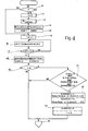
- Figure 4 is a flow chart illustrating the operation of the automatic control system of the present invention.
- With reference to Figure 1, there is schematically shown an electronic injection system for a
heat engine 101, conveniently a four-cylinder engine which is only partially shown in section. This system includes an electroniccentral control unit 102 including, in a substantially known way, amicroprocessor 121 and registers in which there are memorised mappings relating to different operating conditions of theengine 101, as well as various counters and random access memory registers (RAM). - This
central control unit 102 receives signals from:
asensor 103 for detecting the speed of rotation of theengine 101, disposed opposite apulley 104 having four equallyspaced teeth 131 keyed onto acrankshaft 125,
asensor 105 for detecting the phase of theengine 101, positioned in adistributor 126,
asensor 106 for detecting the absolute pressure existing in aninduction manifold 107 of theengine 101,
asensor 108 for detecting the temperature of the air in themanifold 107,
asensor 110 for detecting the temperature of the water in the cooling jacket of theengine 101,
asensor 111 constituted substantially by a potentiometer and a detector for detecting the angular position of abutterfly valve 112 disposed in theinduction manifold 107 and controlled by an accelerator pedal 113: between the zones of theinduction manifold 107 upstream and downstream of thebutterfly valve 112 is connected a supplementaryair supply valve 114 the closure position of which is controlled by thecentral control unit 102; in particular thisvalve 114 can be an electromagnetically controlled valve of the type described in Patent Application number 3386-A/83 filed 12 April 1983 by the same applicant. - This electronic
central control unit 102 is connected to anelectrical supply battery 115 and to earth, and, in dependence on the signals from the said sensors, the speed of rotation of the engine and the density of the air are utilised to determine the quantity of fuel in dependence on the desired mixture strength. Thiscentral control unit 102 therefore controls the duration of opening of the electro-injectors 116 disposed in themanifold 107 close to the induction valve of each respective cylinder, to meter the quantity of fuel provided to the different cylinders of theengine 101 and to control the phasing of the injection to determine the commencement of fuel delivery with respect to the phases (induction, compression, expansion, exhaust) of theengine 101. Each electro-injector 116 is supplied with fuel through apressure regulator 117 sensitive to the pressure in theinduction manifold 107 and having afuel inlet duct 118 for fuel coming from a pump (not illustrated), and areturn duct 119 leading to a reservoir (not illustrated). This electroniccentral control unit 102 is moreover connected to aunit 120 for control of the ignition pulses which are provided to the various cylinders through thedistributor 126, and controls thevalve 114 for controlling the supply of supplementary air in a manner which will be described in more detail hereinbelow, according to the characteristics of the present invention, the principle of operation of which is summarised with reference to Figure 2 which is a graph on which are plotted, along the abscissa, the values of the mixture strength, that is to say the ratio of the quantity of fuel injected to the quantity of air supplied, whilst along the ordinate are plotted the values of engine torque which are proportional to the speed of rotation of the engine. In this graph there is illustrated a curve for constant quantity of fuel (QB) which has maximum, indicated A, which corresponds to the point of maximum economy, which is the condition in which all the fuel injected is burnt. If the mixture strength is varied by varying only the quantity of air supplied, this curve is displaced, and for higher ratios B:A, that is to say richer mixtures, one arrives for example at point P'' in which the engine torque and the speed of rotation fall because part of the fuel is not burnt, whilst for lower ratios B:A, that is to say leaner mixtures, to the left of the point A, again a diminution of the engine torque and of the speed of rotation is experienced in that the excess air reduces the speed of the combustion reaction, which deteriorates. At the calibration point of the mapping of thecentral control unit 102 there is chosen a slightly richer mixture strength than that of point A, that is to say corresponding to point P to compensate the poor distributions and irregularities deriving from the low air density in slow running conditions which are the most critical. - According to the principle of the present invention as can be seen from the graph of Figure 2, a given modulation of the air flow rate will produce different effects on the engine torque, and therefore on the speed of rotation according as it is applied at different points along this curve: the resultant variation in the speed of rotation is proportional to the derivative at the point of application and the phase (that is to say the concordance of sign between the variations of the ratio B:A and the engine torque variations) will be positive for points to the left of point A and negative for points to the right of point A. In this way, with a modulation of the flow rate of supplementary air one can detect the variations in the speed of rotation of the engine and therefore recognise if the displacement of the mixture strength is towards the zone to the left or the zone to the right of the point A, and therefore consequently correct the drift in the mixture strength to maintain it in the desired range of variations.
- With reference to Figure 4, the programme of the electronic injection system controlled by the
microprocessor 121 starts each cycle at astage 10 at which it is detected whether this is the first time this part of the programme for automatic control of the fuel mixture strength in slow running conditions is being performed: in the positive case the programme passed tostage 11 at which the index i is set to 0, and the programme then passes to astage 12 at which the periodic supply of the quantity of supplementary air QA is controlled about a mean value via theelectromagnetic valve 114, and inverted at each period CNTCC determined by a counter of thecentral control unit 102 which is started at a predetermined value and decremented by signals SMOT coming, as can be seen in Figure 3, from thesensor 103 at each 90° of rotation of the engine crankshaft 125 (Figure 1); upon zeroing of this counter CNTCC the control signal to thevalve 114 is modified so as to invert the sign of the variation of quantity of additional air with respect to the mean-value, and the initial value of the counter is renewed for the decremental count which determines the new period CNTCC, which, in conditions of slow running of theengine 101, lasts about 1.25 seconds. The duration of this period CNTCC, and the variation QA of the additional air, equal to about 4% of the air supplied through thebutterfly valve 112 in the slow running conditions, is such as to cause variations in the drive torque which are distinguishable from perturbations which can arise in the engine due to poor stability of the speed of rotation due to other causes. - From the
stage 12 the programme leads to astage 13 which determines via one or more counters the count of respective successive periods, illustrated in Figure 3 and indicated with RIT1, CNTCC1, RIT2, CNTCC2, CNTCC1,...Such periods are determined by the decremental mixture strength in slow running conditions is being performed: in the positive case the programme passed tostage 11 at which the index i is set to 0 (i=0), and the programme then passes to astage 12 at which the periodic supply of the quantity of supplementary air QA is controlled about a mid value via theelectromagnetic valve 114, and inverted at each period CNTCC determined by a counter of thecentral control unit 102 which is started at a predetermined value and decremented by signals SMOT coming, as can be seen in Figure 3, from thesensor 103 at each 90° of rotation of the engine crankshaft 125 (Figure 1); upon zeroing of this counter CNTCC the control signal to thevalve 114 is modified so as to invert the sign of the variation of quantity of additional air with respect to the mean-value, and the initial value of the counter is renewed for the decremental count which determines the new period CNTCC, which, in conditions of slow running of theengine 101, lasts about 1.25 seconds. The duration of this period CNTCC, and the variation QA of the additional air, equal to about 4% of the air supplied through thebutterfly valve 112 in the slow running conditions, is such as to cause variations in the drive torque which are distinguishable from perturbations which can arise in the engine due to poor stability of the speed of rotation due to other causes. - From the
stage 12 the programme leads to astage 13 which determines via one or more counters the count of respective successive periods, illustrated in Figure 3 and indicated with RIT1, CNTCC1, RIT2, CNTCC2, CNTCC1,...Such periods are determined by the decremental count down to zero of a respective counter starting from a predetermined value, and for which there are provided as clock signals the same signal SMOT from thesensor 103 also provided to the counter for determining the period CNTCC as already described. The periods CNTCC1 and CNTCC2 have the function of determining the detection window through which the perturbations of the speed of rotation caused by the introduction of supplementary air QA with the respective increase and decrease with respect to the mean value are determined, whilst the period RIT1 has the function of determining an adequate detection delay with respect to the commencement of the modification of the additional air to take account of the intrinsic delay of the supply and distribution system of the engine, whilst the period RIT2 has the function of taking account of this intrinsic delay in the variations in the sign of the additional air QA with respect to the mean values. - In particular, the period RIT1 is equal to about half the duration of the period CNTCC, the period RIT2 is of substantially negligible duration, whilst the periods CNTCC1 and CNTCC2 are of substantially the same duration, equal to that of the period CNTCC of application, with constant sign, of the quantity Q of the additional air. With the commencement of periodic variation of the quantity of additional air QA the count period RIT1 ceases and is succeeded by counts of periods CNTCC2 and CNTCC1, and so on, with the eventual introduction of the period RIT2. With reference again to Figure 4, part of the
stage 13 is astage 14 which calculates the memories indicated respectively SUM1 and SUM2 the sum of the time intervals between the various signals SMOT in the respective acquisition windows CNTCC1 and CNTCC2 corresponding to the mean speed of rotation in these windows. After thestage 14 there is astage 15 which increments by one unit the value of the index i, putting: i = i + 1, and the programme arrives directly at thisstage 15 in the case of the negative condition detected atstage 10, that is to say in the case of subsequent repetitions of the programme. After thestage 15 is astage 16 at which is calculated, in a register DIFFSUM, the difference between the values in the registers SUM1 and SUM2, that is to say the difference between the mean speeds of rotation in the windows CNTCC1 and CNTCC2 are detected; it must also be noted that since these windows can have different basic durations determined by a different count of signals SMOT, the value calculated in the register SUM1 and SUM2 atstage 14 can be altered to normalise it and make it refer to the same signal count SMOT in the two windows. - After the
stage 16 there is astage 17 which detects if the count window of period CNTCC2 is concluded, that is to say if the associated counter has reached zero: in the negative case it returns tostage 16, whilst in the positive case it passes to astage 18 which puts the value SUMMOD into an associated register equal to the previously memorised value (SUMMOD) to which is added the value DIFFSUM determined atstage 16; atstage 18 the registers SUM1 and SUM2 are then returned to zero. The programme then leads to astage 20 which determines if the index i is equal to N (for example 20) to detect if this modulation cycle of additional air and measurement of the variation of the speed of rotation of theengine 101 indicated Tmi (Figure 3) has been repeated for a sufficient number of times, established by N. In the positive case it leads to astage 21 which detects if the temperature of the engine cooling water detected by thesensor 110 is greater than a predetermined value (T₁), if the speed of rotation of the engine is greater than a predetermined threshold value (RPMO), if the butterfly valve 112 (FARF) is in the minimum position (FARFMIN) and if the value (SUMMOD) of the difference in the speed of rotation between the positive and negative increments of the additional air via thevalve 114, repeated for the predetermined number of cycles N is, in absolute value, greater than a threshold value So, which is indicative of a displacement of the speed of rotation of the engine, and therefore of the mixture strength, at slow running of the engine, greater than the admissible range of variation. In the positive case the programme passes tostage 22 which evaluates if the value of the parameter SUMMOD is positive or negative; in the first case this is indicative of a displacement from the point P (Figure 2) towards the point P", that is to say in the section of the curve to the right of the point A, so that it is necessary to reduce the quantity of fuel injected to bring the point P" back towards the point P, and therefore the additional regulation time for disablement of theinjector 116 is calculated in an incremented manner, that is to say equal to: - TRIM = TRIM + K (SUMMOD - So)
- On the other hand if the value SUMMOD is negative, this indicates that the point P is in the zone to the left of the point A (point P'), that is to say the mixture strength is displaced towards leaner mixture conditions so that it is necessary to reduce the disablement time of the injector, and the correction parameter TRIM is put equal to:
- TRIM = TRIM - K (SUMMOD - So)
- From the
stage 22 the programme then passes to astage 23 which puts the value SUMMOD in the respective registers equal to zero, and likewise zeros the index i to enable successive cycles of calculation of this automatic control system of the slow running mixture strength. After thestage 23 there is then astage 25 which controls the subsequent operation of the programme through themicrocomputer 121 for actuation of sequential and phased controls supplied to theelectro injectors 116. The programme passes directly to thisstage 25 in the case of negative conditions established atstage 20, that is to say if the repetitive cycles of modulation of the additional air and measurement of the variation of the speed of rotation of the engine have not been performed for the total desired number N of cycles, or in the case of negative conditions established by thestage 21, that is to say, if the temperature of the cooling water of the engine is relatively low, if the speed of rotation is low, if thebutterfly valve 112 is not in its minimum position, or if the variation of the speed of rotation (SUMMOD) does not exceed the predetermined threshold value So, that is to say, if the variation of the mixture strength has not passed out of the desired range, which implies that the operating point is around the initially established point P of Figure 2. - The advantages obtained with the automatic slow running mixture strength control system formed according to the present invention are apparent from what has been described above in that the periodic calibration operations by the operater are now eliminated with a guarantee that the engine will always function within the desired range of parameters.
- Finally it is clear that the embodiment of the automatic control system of the present invention described can be modified and varied without departing from the scope of the invention itself.
Claims (12)
Applications Claiming Priority (2)
| Application Number | Priority Date | Filing Date | Title |
|---|---|---|---|
| IT6780185 | 1985-09-20 | ||
| IT67801/85A IT1182558B (en) | 1985-09-20 | 1985-09-20 | AUTOMATIC CONTROL SYSTEM IN MINIMUM ROTATION CONDITIONS OF THE TYPE OF COMBUSTIBLE MIXTURE ADOPTED TO AN ENDOTHERMAL ENGINE COMORENDING AN ELECTRONIC INJECTION SYSTEM |
Publications (3)
| Publication Number | Publication Date |
|---|---|
| EP0215411A2 true EP0215411A2 (en) | 1987-03-25 |
| EP0215411A3 EP0215411A3 (en) | 1987-11-04 |
| EP0215411B1 EP0215411B1 (en) | 1990-02-07 |
Family
ID=11305393
Family Applications (1)
| Application Number | Title | Priority Date | Filing Date |
|---|---|---|---|
| EP86112395A Expired EP0215411B1 (en) | 1985-09-20 | 1986-09-08 | A system for automatic control of the fuel mixture strength supplied in slow running conditions to a heat engine having an electronic fuel injection system |
Country Status (6)
| Country | Link |
|---|---|
| US (1) | US4847771A (en) |
| EP (1) | EP0215411B1 (en) |
| BR (1) | BR8604595A (en) |
| DE (1) | DE3668945D1 (en) |
| ES (1) | ES2002183A6 (en) |
| IT (1) | IT1182558B (en) |
Cited By (1)
| Publication number | Priority date | Publication date | Assignee | Title |
|---|---|---|---|---|
| FR2739141A1 (en) * | 1995-09-27 | 1997-03-28 | Siemens Automotive Sa | METHOD FOR DETERMINING THE OPTIMAL WEALTH OF AN AIR / FUEL MIXTURE SUPPLYING AN INTERNAL COMBUSTION ENGINE AND CORRESPONDING DEVICE |
Families Citing this family (9)
| Publication number | Priority date | Publication date | Assignee | Title |
|---|---|---|---|---|
| US6220878B1 (en) | 1995-10-04 | 2001-04-24 | Methode Electronics, Inc. | Optoelectronic module with grounding means |
| US5717533A (en) | 1995-01-13 | 1998-02-10 | Methode Electronics Inc. | Removable optoelectronic module |
| US5546281A (en) | 1995-01-13 | 1996-08-13 | Methode Electronics, Inc. | Removable optoelectronic transceiver module with potting box |
| US5937826A (en) * | 1998-03-02 | 1999-08-17 | Cummins Engine Company, Inc. | Apparatus for controlling a fuel system of an internal combustion engine |
| US6203333B1 (en) | 1998-04-22 | 2001-03-20 | Stratos Lightwave, Inc. | High speed interface converter module |
| US6179627B1 (en) | 1998-04-22 | 2001-01-30 | Stratos Lightwave, Inc. | High speed interface converter module |
| US6220873B1 (en) | 1999-08-10 | 2001-04-24 | Stratos Lightwave, Inc. | Modified contact traces for interface converter |
| US6725147B2 (en) | 2001-10-31 | 2004-04-20 | International Engine Intellectual Property Company, Llc | System and method for predicting quantity of injected fuel and adaptation to engine control system |
| AT516532B1 (en) * | 2014-11-24 | 2019-10-15 | Innio Jenbacher Gmbh & Co Og | Method for starting an internal combustion engine operated with a fuel-air mixture |
Citations (4)
| Publication number | Priority date | Publication date | Assignee | Title |
|---|---|---|---|---|
| US4064846A (en) * | 1975-02-19 | 1977-12-27 | Robert Bosch Gmbh | Method and apparatus for controlling an internal combustion engine |
| US4448171A (en) * | 1981-06-08 | 1984-05-15 | Nippondenso Co., Ltd. | Method and apparatus for optimum control of internal combustion engines |
| US4479476A (en) * | 1981-01-26 | 1984-10-30 | Nippondenso Co., Ltd. | Method and apparatus for optimum control of internal combustion engines |
| US4487186A (en) * | 1978-10-28 | 1984-12-11 | Robert Bosch Gmbh | Method and apparatus for optimizing the operational variables of an internal combustion engine |
Family Cites Families (21)
| Publication number | Priority date | Publication date | Assignee | Title |
|---|---|---|---|---|
| FR2180182A5 (en) * | 1972-04-12 | 1973-11-23 | Sopromi Soc Proc Modern Inject | |
| US3960320A (en) * | 1975-04-30 | 1976-06-01 | Forney Engineering Company | Combustion optimizer |
| JPS5578138A (en) * | 1978-12-06 | 1980-06-12 | Nissan Motor Co Ltd | Idling speed control for internal combustion engine |
| JPS55160132A (en) * | 1979-05-31 | 1980-12-12 | Nissan Motor Co Ltd | Revolution controller of internal combustion engine |
| JPS5644431A (en) * | 1979-09-14 | 1981-04-23 | Nippon Denso Co Ltd | Method of controlling revolution speed of engine |
| JPS5751934A (en) * | 1980-09-16 | 1982-03-27 | Toyota Motor Corp | Idling revolution speed controller in internal combustion engine |
| JPS5759040A (en) * | 1980-09-26 | 1982-04-09 | Toyota Motor Corp | Intake air flow controlling process in internal combustion engine |
| JPS5770953A (en) * | 1980-10-22 | 1982-05-01 | Nippon Denso Co Ltd | Ignition timing control method |
| JPS58124041A (en) * | 1982-01-19 | 1983-07-23 | Nippon Denso Co Ltd | Air-fuel ratio control device for vehicle |
| JPS58176469A (en) * | 1982-04-12 | 1983-10-15 | Nippon Soken Inc | Method of and apparatus for controlling air-fuel ratio of internal-combustion engine |
| JPS58190530A (en) * | 1982-04-20 | 1983-11-07 | Honda Motor Co Ltd | Feed back control method of idle revolution of internal- combustion engine |
| WO1984000581A1 (en) * | 1982-07-27 | 1984-02-16 | Marchal Equip Auto | Method for self-adaptive regulation of the ignition advance angle of a thermal engine with controlled ignition |
| DE3336028C3 (en) * | 1983-10-04 | 1997-04-03 | Bosch Gmbh Robert | Device for influencing control variables of an internal combustion engine |
| KR890000497B1 (en) * | 1983-11-21 | 1989-03-20 | 가부시기가이샤 히다찌세이사꾸쇼 | Method of controlling air fuel ratio |
| DE3347664A1 (en) * | 1983-12-31 | 1985-07-11 | Dr. C. Otto & Co Gmbh, 4630 Bochum | NOZZLE SHEET CONSTRUCTION FOR UNDERBURNER COOKING OVENS |
| JPS6181546A (en) * | 1984-09-28 | 1986-04-25 | Honda Motor Co Ltd | Feedback control method for number of idle revolutions of internal-combustion engine |
| JPH0612089B2 (en) * | 1984-10-15 | 1994-02-16 | 本田技研工業株式会社 | Idle speed feedback control method for internal combustion engine |
| US4690121A (en) * | 1985-02-16 | 1987-09-01 | Honda Giken Kogyo Kabushiki Kaisha | Air intake side secondary air supply system for an internal combustion engine with a duty ratio control operation |
| JP2542568B2 (en) * | 1985-04-02 | 1996-10-09 | 三菱電機株式会社 | Internal combustion engine speed control device |
| JPH0647962B2 (en) * | 1985-07-09 | 1994-06-22 | 日本電装株式会社 | Idle speed control device for internal combustion engine |
| JP2679970B2 (en) * | 1985-10-21 | 1997-11-19 | 株式会社日立製作所 | Idle rotation speed control device |
-
1985
- 1985-09-20 IT IT67801/85A patent/IT1182558B/en active
-
1986
- 1986-09-08 DE DE8686112395T patent/DE3668945D1/en not_active Expired - Fee Related
- 1986-09-08 EP EP86112395A patent/EP0215411B1/en not_active Expired
- 1986-09-12 US US06/907,309 patent/US4847771A/en not_active Expired - Fee Related
- 1986-09-19 ES ES8602047A patent/ES2002183A6/en not_active Expired
- 1986-09-19 BR BR8604595A patent/BR8604595A/en not_active IP Right Cessation
Patent Citations (4)
| Publication number | Priority date | Publication date | Assignee | Title |
|---|---|---|---|---|
| US4064846A (en) * | 1975-02-19 | 1977-12-27 | Robert Bosch Gmbh | Method and apparatus for controlling an internal combustion engine |
| US4487186A (en) * | 1978-10-28 | 1984-12-11 | Robert Bosch Gmbh | Method and apparatus for optimizing the operational variables of an internal combustion engine |
| US4479476A (en) * | 1981-01-26 | 1984-10-30 | Nippondenso Co., Ltd. | Method and apparatus for optimum control of internal combustion engines |
| US4448171A (en) * | 1981-06-08 | 1984-05-15 | Nippondenso Co., Ltd. | Method and apparatus for optimum control of internal combustion engines |
Cited By (3)
| Publication number | Priority date | Publication date | Assignee | Title |
|---|---|---|---|---|
| FR2739141A1 (en) * | 1995-09-27 | 1997-03-28 | Siemens Automotive Sa | METHOD FOR DETERMINING THE OPTIMAL WEALTH OF AN AIR / FUEL MIXTURE SUPPLYING AN INTERNAL COMBUSTION ENGINE AND CORRESPONDING DEVICE |
| WO1997012135A1 (en) * | 1995-09-27 | 1997-04-03 | Siemens Automotive S.A. | Method for determining an optimal air-fuel mixture ratio in an internal combustion engine, and device therefor |
| US5992381A (en) * | 1995-09-27 | 1999-11-30 | Siemens Automotive S.A. | Process for determining the optimal richness of a fuel-air mixture supplied to an internal combustion engine and corresponding device |
Also Published As
| Publication number | Publication date |
|---|---|
| EP0215411B1 (en) | 1990-02-07 |
| EP0215411A3 (en) | 1987-11-04 |
| US4847771A (en) | 1989-07-11 |
| ES2002183A6 (en) | 1988-07-16 |
| BR8604595A (en) | 1987-05-26 |
| DE3668945D1 (en) | 1990-03-15 |
| IT1182558B (en) | 1987-10-05 |
| IT8567801A0 (en) | 1985-09-20 |
Similar Documents
| Publication | Publication Date | Title |
|---|---|---|
| US4403584A (en) | Method and apparatus for optimum control for internal combustion engines | |
| US4676215A (en) | Method and apparatus for controlling the operating characteristic quantities of an internal combustion engine | |
| US5586537A (en) | Fuel property detecting apparatus for internal combustion engines | |
| US5806497A (en) | Method of and apparatus for controlling fuel injection of internal combustion engine | |
| WO1993016278A1 (en) | Air fuel ratio control | |
| US6644274B2 (en) | Apparatus for detecting a condition of burning in an internal combustion engine | |
| EP0215411B1 (en) | A system for automatic control of the fuel mixture strength supplied in slow running conditions to a heat engine having an electronic fuel injection system | |
| EP0084116A2 (en) | Fuel injection timing control system for an internal-combustion engine, and control method therefor | |
| US4911131A (en) | Fuel control apparatus for internal combustion engine | |
| GB2266975A (en) | Fuel metering control | |
| US5003955A (en) | Method of controlling air-fuel ratio | |
| GB2113428A (en) | Control of idling speed in internal combustion engines | |
| GB2297176A (en) | Method for adapting warming-up enrichment | |
| EP0215412B1 (en) | A system for correction of the fuel injection time, upon variations in altitude, for a heat engine having an electronic injection system | |
| EP0194019A2 (en) | Engine idle speed control system | |
| US4977876A (en) | Fuel injection control system for internal combustion engine with fuel cut-off control at high engine speed range suppressive of recovery shock upon fuels resumption | |
| US4563994A (en) | Fuel injection control apparatus | |
| EP0534506B1 (en) | Air/fuel ratio control system for internal combustion engine with asynchronous fuel delivery control | |
| US4800860A (en) | Fuel injection control system for internal combustion engine with precisely engine load dependent fuel injection amount adjustment feature | |
| US5211148A (en) | Method of and an apparatus for controlling assist air in an internal combustion engine | |
| US4721086A (en) | System for controlling fuel injectors to open asynchronously with respect to the phases of a heat engine | |
| US4850326A (en) | Apparatus for learning and controlling air/fuel ratio in internal combustion engine | |
| US4736722A (en) | System for automatically defining the minimum setting of an accelerator-controlled valve for supplying an internal combustion engine | |
| US4787358A (en) | Fuel supply control system for an engine | |
| EP0230638B1 (en) | A system for the rapid correction of the fuel mixture strength supplied to a heat engine having an electronic injection system |
Legal Events
| Date | Code | Title | Description |
|---|---|---|---|
| PUAI | Public reference made under article 153(3) epc to a published international application that has entered the european phase |
Free format text: ORIGINAL CODE: 0009012 |
|
| AK | Designated contracting states |
Kind code of ref document: A2 Designated state(s): DE FR GB NL SE |
|
| PUAL | Search report despatched |
Free format text: ORIGINAL CODE: 0009013 |
|
| AK | Designated contracting states |
Kind code of ref document: A3 Designated state(s): DE FR GB NL SE |
|
| 17P | Request for examination filed |
Effective date: 19880429 |
|
| RAP1 | Party data changed (applicant data changed or rights of an application transferred) |
Owner name: WEBER S.R.L. |
|
| 17Q | First examination report despatched |
Effective date: 19880912 |
|
| GRAA | (expected) grant |
Free format text: ORIGINAL CODE: 0009210 |
|
| AK | Designated contracting states |
Kind code of ref document: B1 Designated state(s): DE FR GB NL SE |
|
| ET | Fr: translation filed | ||
| REF | Corresponds to: |
Ref document number: 3668945 Country of ref document: DE Date of ref document: 19900315 |
|
| PGFP | Annual fee paid to national office [announced via postgrant information from national office to epo] |
Ref country code: SE Payment date: 19900809 Year of fee payment: 5 |
|
| PGFP | Annual fee paid to national office [announced via postgrant information from national office to epo] |
Ref country code: NL Payment date: 19900930 Year of fee payment: 5 |
|
| PLBE | No opposition filed within time limit |
Free format text: ORIGINAL CODE: 0009261 |
|
| STAA | Information on the status of an ep patent application or granted ep patent |
Free format text: STATUS: NO OPPOSITION FILED WITHIN TIME LIMIT |
|
| 26N | No opposition filed | ||
| PG25 | Lapsed in a contracting state [announced via postgrant information from national office to epo] |
Ref country code: SE Effective date: 19910909 |
|
| PG25 | Lapsed in a contracting state [announced via postgrant information from national office to epo] |
Ref country code: NL Effective date: 19920401 |
|
| NLV4 | Nl: lapsed or anulled due to non-payment of the annual fee | ||
| EUG | Se: european patent has lapsed |
Ref document number: 86112395.8 Effective date: 19920408 |
|
| PGFP | Annual fee paid to national office [announced via postgrant information from national office to epo] |
Ref country code: FR Payment date: 20000829 Year of fee payment: 15 |
|
| PGFP | Annual fee paid to national office [announced via postgrant information from national office to epo] |
Ref country code: GB Payment date: 20000906 Year of fee payment: 15 |
|
| PGFP | Annual fee paid to national office [announced via postgrant information from national office to epo] |
Ref country code: DE Payment date: 20001128 Year of fee payment: 15 |
|
| PG25 | Lapsed in a contracting state [announced via postgrant information from national office to epo] |
Ref country code: GB Free format text: LAPSE BECAUSE OF NON-PAYMENT OF DUE FEES Effective date: 20010908 |
|
| GBPC | Gb: european patent ceased through non-payment of renewal fee |
Effective date: 20010908 |
|
| PG25 | Lapsed in a contracting state [announced via postgrant information from national office to epo] |
Ref country code: DE Free format text: LAPSE BECAUSE OF NON-PAYMENT OF DUE FEES Effective date: 20020501 |
|
| PG25 | Lapsed in a contracting state [announced via postgrant information from national office to epo] |
Ref country code: FR Free format text: LAPSE BECAUSE OF NON-PAYMENT OF DUE FEES Effective date: 20020531 |
|
| REG | Reference to a national code |
Ref country code: FR Ref legal event code: ST |