EP0213640A2 - Demand assigned reformatting with an overflow area for time division multiple access communication - Google Patents
Demand assigned reformatting with an overflow area for time division multiple access communication Download PDFInfo
- Publication number
- EP0213640A2 EP0213640A2 EP86112326A EP86112326A EP0213640A2 EP 0213640 A2 EP0213640 A2 EP 0213640A2 EP 86112326 A EP86112326 A EP 86112326A EP 86112326 A EP86112326 A EP 86112326A EP 0213640 A2 EP0213640 A2 EP 0213640A2
- Authority
- EP
- European Patent Office
- Prior art keywords
- frame
- burst
- station
- assigned
- sub
- Prior art date
- Legal status (The legal status is an assumption and is not a legal conclusion. Google has not performed a legal analysis and makes no representation as to the accuracy of the status listed.)
- Withdrawn
Links
Images

Classifications
-
- H—ELECTRICITY
- H04—ELECTRIC COMMUNICATION TECHNIQUE
- H04B—TRANSMISSION
- H04B7/00—Radio transmission systems, i.e. using radiation field
- H04B7/14—Relay systems
- H04B7/15—Active relay systems
- H04B7/204—Multiple access
- H04B7/212—Time-division multiple access [TDMA]
- H04B7/2121—Channels assignment to the different stations
- H04B7/2123—Variable assignment, e.g. demand assignment
Definitions
- the invention relates generally to communication systems.
- the invention relates to the dynamic reformatting of a time division multiple access frame dependent upon the demand of the attached stations.
- TDMA time division multiple access
- data is not transmitted continuously but is time multiplexed.
- the transmission is divided into time frames 14 and 16 with each frame being further subdivided, according to a predetermined format, into traffic bursts TB.
- traffic bursts TB Both data and voice signals are transmitted in digital form.
- the frames repeat often enough that a telephone coversation can be made to appear continuous and instantaneous.
- each ground station 10 is assigned one traffic burst.
- the transmission of the traffic bursts from the individual ground stations 10 are synchronized so that they arrive at the satellite 12 in the proper time sequence to form the up-link frame 14.
- the communication satellite 12 receives the up-link frame 14 and retransmits the frame as the down-link framep 16.
- the satellite 12 can be viewed as a passive transponder with the up-link frame 14 being identical to the down-link frame 16. It is of course to be appreciated that the frames 14 and 16 illustrated in Figure 1 are only one pair of a nearly continuous series of up-link frames and down-link frames, the frames in each series being separated by the minimum necessary time.
- the entire down-link frame 16 is received by each of the N stations 10 so tht each station 10 is receiving the transmissions of every other station 10.
- the individual traffic burst TB must contain additional information indicating for which of the ground stations 10 the transmission is intended.
- a reference station 18 is usually present to provide some degree of coordination between the ground stations 10. At a minimum, the reference station 18 must synchronize the ground stations 10 so that the frames 14 and 16 are synchronized between the stations 10 and furthermore it synchronizes the traffic bursts TB within the frame.
- Bandwidth is both scarce and, in the case of the satellite 12, expensive to support because of the correspondingly increased power level.
- the excess capacity required for a high availability with a fixed format implies a decreased number of reliably available channels.
- DAMA demand assigned multiple access
- SPADE single channel per carrier satellite communication systems
- each earth station 10 communicates with all other stations 10 via a wide band common signalling channel. All call requests are communicated via this channel among all the stations 10 in the network.
- the different carrier channels, corresponding to different frequencies, are allocated to the different ground stations 10, according to these requests.
- Each station 10 maintains a data base that represents the frequency assignments for all carrier frequencies in the transponder of a satellite 12.
- the SPADE system represents a decentralized approach to channel allocation.
- Patent 4,204,093, or of Rothauser et al. in U.S. Patent 4,096,355 although efficient in call channel capacity, introduces excessive complexity and delays caused by the rapidly changing system configuration.
- Torng in U.S. Patent 4,383,315 and Fennel, Jr. et al in U.S. Patent 4,322,845 disclose a mixture of centralized and decentralized control. These problems with totally centralized or decentralized control will now be explained.
- the process of establishing a communication link between earth stations 10 requires the originating earth station to process the incoming call request from the telephone lines to determine the destination for this call. This call processing will result in a request for a portion of the TDMA frame in which to carry the traffic associated with the call, whether it be for voice or data communication. If a full duplex connection is required, as is the case for a typical voice call, then two requests will be generated. For a typical satellite transponder, between two and four call requests per second can be expected. Larger systems are designed with multiple transponders so that multiple frames are being received simultaneously.
- the allocation, or management of the TDMA frame can be either centralized at the reference station 18 or decentralized among the ground stations 10.
- Grade of service is the probability that a call request cannot be honored by a station 10 because no space can be allocated to it. Obviously in a consumer market, the overall GOS should be minimized to prevent the undue occurrence of busy signals. As the number of calls approaches the number of available channels, the grade of service deteriorates, that is, GOS increases. A typical relation between the percentage usage of the channels and the grade of service is shown in Figure 2, presented solely for illustrative purposes. Such curves vary depending upon system design. For an economically efficient system, the number of calls should approach the number of channels. However, this increased efficiency inevitably degrades the grade of service.
- An erlang is another measure of channel usage, particularly appropriate for TDMA systems.
- An erlang is the number of call-seconds per second for the system as whole. Obviously, a higher number of erlangs implies an efficiently used system. Because there are multiple channels handling multiple calls in a TDMA system, a TDMA system typically has an erlang value greater than one.
- the 2-4 call requests per second will require a very large computer at the reference station 18. The call requests all pass through the communication satellite 12 located approximately 36,000 miles above the ground stations 10 and the reference station 18. As a result, the delays associated with the propagation of the request to the reference station 18 and of the reply to the requesting station 10 can become appreciable, approaching 1 second.
- Each ground station 10 must reconfigure its timing controls to conform to a reconfigured TDMA frame. If this reconfiguration is occuring at the rate of 2-4 times a second, the frame management processing at each of the ground stations 10 becomes appreciable and additional channel capacity must be provided for the frequent call requests and resultant reconfiguration data. It is to be remembered that in a frequency division system, the frequencies are individually allocated so that the reallocation of one frequency does not require a complete reallocation of all the frequencies.
- each earth station 10 would have one segment or traffic burst of the TDMA frame for which it had the management responsibility.
- the total network traffic capacity would be a function of the number of stations 10 in the network since each station must maintain a separate reserve capacity to satisfy the required grade of service.
- the fully decentralized approach would support 320 erlangs of full duplex traffic, a reduction from the 425 erlangs of the totally centralized approach.
- the number of stations is increased to 100, the maximum full duplex traffic that could be supported falls further to 166 erlangs.
- system delays and complexity are reduced in the fully decentralized TDMA system but only at the expense of a significantly reduced traffic capacity.
- the invention can be summerized as a method of frame management in a time division multiple access communication system in which a fixed time frame is divided into segments that are assigned to separate stations. Each station is responsible for the management of its own segment.
- the frame is further provided with an overflow area. Whenever a station overflows the capacity of its own assigned segment, a request is made to a central station to assign a small slot in the overflow area to that station. The control of the slot reverts to the central station when its use by the station terminates.
- the TDMA frame is divided into a preallocated segment and an overflow segment. Every station is given a portion of the preallocated segment over which it exercises control. Whenever a station requires additional channel capacity that cannot be satisfied by its preallocated portion, it requests the reference station to allocate it part of the overflow segment. The reference station thus controls the overflow segment.
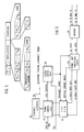
- FIG. 3 One embodiment of the format for a TDMA frame of the present invention is shown in Figure 3.
- the frame begins with two reference bursts RB A and RB B which are separately assigned to each of two reference stations. Two independent reference stations are provided to provide redundancy and thus additional reliablity. Only one reference station at any one time is exercising control over the system. It is only when the first reference station fails that the second reference station asserts control over the system. Accordingly, the remaining discussion will assume only a single controlling reference station 10.
- the reference bursts RB A and RB B contain the transmissions of the reference stations 18. These transmissions include information about its own health as well as control information for the satellite 12 and for the individual ground stations 10. The control informaion allows all ground stations 10 to be synchronized with the reference station 18.
- a preallocated segment is subdivided into traffic bursts TB1-TB N .
- Each of the traffic bursts are assigned to one of the N ground stations 10.
- the size of the individual traffic bursts TB1-TB N varies according to the needs of the individual ground stations 10.
- the size at the traffic bursts TB1-TB N are chosen so that the GOS of each traffic burst is held in the range of 0.05-0.30. These sizes are selected by the reference station 18 but only on a fairly infrequent basis, for example, half-hourly.
- the i-th ground station 10 to which the traffic bursts TB i is assigned has control of that traffic burst TB i .
- the format of a preallocated traffic burst TB i is also shown in Figure 3. It begins with a preamble PRE, used for control information. This control information is used by the ground station 10 to acquire a burst and to identify the beginning of the data portion of the burst.
- the traffic burst TB i contains a broadcast channel. This broadcast channel is of fixed size and is always allocated to the respective ground station 10. Typically, the broadcast channel is used for control and status information transmission and not for telephone calls. It is thus assumed that the broadcast channel is always needed by the respective ground station 10.
- sub-bursts SB1-SB K Following the broadcast channel are a plurality of slots that are assigned to variable length sub-bursts SB1-SB K . Unused slots are kept in a spare area. Each of the sub-bursts SB1-SB K is associated with one telephone/data call. The ground station maintains control over the allocation of the sub-bursts to the slots. As illustrated in Figure 3, it is assumed that the sub-bursts SB1-SB K have been compacted to the left so that all spare slots appear on the right. Compaction is not required for the practice of the invention.
- the overflow area of the TDMA frame is also divided into a number of slots.
- Each of the overflow slots is assigned to one of the traffic bursts TB'1-TB' M .
- Unused slots represent spare overflow capacity.
- Each of the overflow traffic bursts TB' i consists of a preamble PRE and an overflow sub-burst SB.
- the overflow sub-burst SB is the same size as would be required for a preallocated sub-burst SB i and thus corresponds to a single telephone call.
- the i-th ground station 10 In operation, whenever the i-th ground station 10 receives a request for a telephone/data connection from one of its lines, it first attempts to find preallocated spare capacity in its own traffic burst TB i so that it can add another sub-burst SB i thereto. If the spare capacity is available, the call can be completed through the satellite 12 without the assistance of the reference station 18. If, however, existing traffic sub-bursts SB1-SB K completely fill the traffic burst TB i so that no preallocated spare capacity remains, then the ground station 10 signals the reference station 18 that a channel is required. The reference station 18 then attempts to find spare capacity in the overflow segment for the insertion of another overflow traffic bursts TB' i .
- the reference station 18 makes the allocation and then transmits this fact to the requesting ground station 10.
- the ground station 10 then associates the telephone call with the sub-burst SB of the newly allocated overflow traffic burst TB' i . If the overflow space capacity was not initially available, the reference station 18 so notifies the requesting ground station 10 and the telephone call is blocked.
- the ground station 10 originating that call receives a call clear message and then sends an overflow slot release message to the reference station 18.
- the reference station 18 reassigns the new vacant overflow traffic burst to its spare capacity.
- All information concerning the destination of the sub-bursts SB and SB i is transmitted from the ground stations 10 in the broadcast channel.
- the formatting control is both centralized and decentralized.
- the control is decentralized in the respect that each of the ground stations 10 exercises control of its own preallocated traffic burst TB i .
- Control is centralized in the respect that the reference station 18 maintains control over all of the overflow segment.
- the centralized control by the reference station 18 is required only when the respective preallocated traffic bursts TB i does not have spare capacity. Thus a large fraction of the control is decentralized.
- the GOS in the preallocated traffic bursts TB1-TB N are in the range of 0.05-0.30, the overall GOS is about 0.01.
- the dynamic reformatting capability of this invention is being built into a communication system which initially includes 30 ground stations.
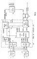
- a simplified electronic structure for each ground station is shown in the block diagram of Figure 4.
- Terrestrial interface equipment is composed of any number of plesiochronous CEPT-32 interface units (CIUs) 30 and asynchronous/synchronous pulse-stuffing CEPT-32 interface units 32, operating at 2048 kilobits per second.
- the plesiochronous CIU 30 buffers data and signaling information between the ground station and the terrestrial telephone network.
- One plesiochronous CIU 30 provides for a duplex interface for one CEPT-32 terrestrial digital trunk.
- Inherent in the design of the plesiochronous CIU 30 is a split-channel capability.
- the plesiochronous CIU 30 is designed to operate in either synchronous or plesiochronous mode, that is, in either a master or slave mode.
- the asynchronous/synchronous pulse-stuffing CIU 32 provides a duplex interface to the ground station for an asynchronous 2.048 megabyte per second data string and is fully compatible with CCITT Recommendations G.703 and G.912.
- the pulse-stuffing CIU 32 performs bit stuffing on the incoming data stream to synchronize it to the ground station. In addition, it compresses this continuous data stream into a burst suitable for transmission over the satellite. On the receive side, the high speed data bursts received from the satellite are expanded into a continuous low speed data stream. Bit destuffing is then performed to restore the rate and the content of the data stream, which is then sent to the terrestrial telephone network.
- transmission data is modulated by a MODEM 34 at an IF frequency of 70 MHz and sent to a transmitter, not shown, which further modulates the IF data to the RF transmission frequency.
- An RF receiver not shown, receives the down link transmissions from the satellite. There are, in fact, four separate transponders and the receiver provides separate IF receive lines FQ1-FQ4 for the four channels.
- An IF switch 36 selects one of these four IF lines FQ1-FQ4 for connection to the receive input of the MODEM 34.
- the MODEM 34 provides the functions of interfacing the data, clock and control signals. It is a QPSK modulator/demodulator and provides the carrier source for the 70 MHz IF carrier. The MODEM 34 further provides control and IF loop back switches. When the MODEM is receiving data from the satellite, it recovers the clock from the received signal.
- a differential driver/receiver interface 33 converts single-ended bus related signals on the telephone network side into a differential form for transmission within the chassis.
- Frame management processor equipment is the heart of a ground station. It is a microprocessor-based subsystem which controls the operation of the ground station.
- the frame management processor equipment performs several principal functions. The equipment acquires and keeps track of the satellite frame with a nominal frame length of 18 ms. It keeps the local TDMA clock frequency locked to the received signal.
- the frame management processor equipment transmits the ground stations traffic bursts at their assigned time position in its allocated time slot. It multiplexes voice, data and, if desired, video sub-bursts derived from digital trunks in the terrestrial telephone network.
- the frame management processor equipment accepts call requests from the telephone network and establishes a sub-burst for those requests. The assignment of the sub-bursts must be made in conjunction with the destination ground station and additionally, if the overflow pool is to be used, in conjunction with the reference station.
- a signal and coding module 42 performs two primary functions. First of all, it performs the error correction encoding and decoding of the traffic data in order to improve the bit error rate of the traffic channel over the satellite link.
- the second function of the signal and coding module 42 is that of message handling for all control information exchanged between processors of different ground stations and the reference station. This control information is transmitted in the broadcast channel that is the first sub-burst of every burst, except for the overflow traffic burst TB' i of the overflow pool.
- a high speed module 44 performs those functions that deal directly with the serialized satellite data and the high speed, 29.952 MHz clock. These functions include the serializing/deserializing of data between the serial data link and the parallel buses of the frame management processor equipment 38.
- the high speed module 44 transmits the frame start timing and retimes the data received from the demodulator to the local clock. It further generates and adjusts the local clock.
- a control RAM 46 in conjunction with a frame management CPU 48 forms a microprocessor based control-sequence generator.
- the events occuring during each TDMA frame are controlled by this sequence of control and address signals.
- the sequence lasts the length of the frame.
- the sequence can be changed by the frame mangement CPU 48 on a frame-by-frame basis.
- Two independent control sequences are generated, one each for the transmit side and the receive side pipelines of the frame management processor equipment 38.
- the sequences consist of a linked series of control words. Each control word corresponds to a frame-related event.
- the events occur during each satellite frame and the duration of those events are stored as words in the control RAM 46.
- Twelve of the 32-bits within the control words are addresses for the buses to the CIUs 30 and 32.
- Other bits are used as control bits for various activities including the loading of a counter which controls the length of time an address stays on the bus.
- Other bits are used for system control functions such as gating the carrier and turning the error correction
- the frame management CPU 48 is a general purpose microcomputer, system, designed specifically for use as an intelligent controller/computer in various roles throughout the entire communication system.
- the same basic hardware module is used in four different applications as a CPU.
- the frame management CPU 48 provides three primary functions. It controls the structure of the frame by loading the control RAM 46 with microinstructions which form the sequence of outputs produced by that control RAM 46. It acquires and maintains synchronization of the frame by monitoring the reference burst position and by adjusting the system clock frequency through its interface with the high speed module 44. It also monitors the status of the modules attached to its bus 50 and generates status messages for the reference station. These messages are sent through the satellite via the signal and coding module 42. The status messages include requests to the reference ground station for an additional sub-burst TB' i in the overflow pool. When a call in the overflow pool has been completed, the disconnection requests is likewise sent from the frame management CPU 48 to the reference station in a status message. The reference station also makes use of the information contained in the status messages to perform its periodic reformatting of the preallocated traffic bursts TB i .
- a single management CPU 52 is a microprocessor-based subsystem physically identical to the frame management CPU 48.
- the signal management CPU 52 transfers and formats signalling data between the CIUs 30 and 32 and the satellite channel. Thus, a request for a call connection enters the frame management processor 38 through the signal management CPU 52.
- the reference station is used to maintain network synchronization and control of the TDMA burst time plan.
- the electronics of the reference station shown in Figure 5, provides the following functions. It provides the control mechanism so that all ground stations can access the satellite and not interfere with one another. Furthermore, it provides the TDMA frame management functions for operating the communication system in a demand assign mode.
- the equipment of the reference station closely resembles the equipment shown in Figure 4 for the ground stations.
- the MODEM 34 for the reference station is the same as for a ground station.
- a frame management processor equipment 60 is identical to the frame management processor equipment 38 of the ground station with the major exception that the reference station does not contain a signal management CPU 52.
- the DDR interface 40 within the frame management processor equipment 60 instead of being connected to CIUs 30 and 32 as in the ground stations, is instead connected to a frame supervisory processor signal and coding module 62.
- Other parts of the frame supervisory processor are a frame supervisory CPU 64, a clock distribution unit 66 and an ETHERNET interface module 68.
- the frame supervisory processor signal and coding module 62 is the same as the signal and coding modules 42 within the ground stations. There are some differences in functionality when the signal and coding module 62 is used in the reference station.
- Some circuitry in the signal and coding module 42 of the ground station is not used in the reference station and vice versa.
- the only forward error correction circuitry used in the frame supervisory processor is for correction of the broadcast channel.
- the forward error correction circuitry for traffic data is not needed since the reference station does not carry traffic.
- the signal and coding module 62 in the frame supervisory processor contains an additional circuit which is not used in a ground station. This circuitry provides the aperture for monitoring the position error traffic bursts and is used to generate a correction signal for correcting this burst position at the ground station.
- the frame supervisory CPU 64 is physically identical to the frame management CPU 48 in the ground station. It interfaces with the frame management processor equipment 60, the ETHERNET interface module 68 and the frame supervisory processor signal and coding module 62.
- the frame supervisory CPU 64 does not interface to the frame management processor CPU 48 via a common, arbitrated bus as does the signal management CPU 42 in a ground station. Instead, the frame supervisory CPU 64 interfaces via an HDLC link to the frame management processor equipment 60.
- HDLC stands for high level data link controller and represents a standard protocol in the industry.
- the ETHERNET interface module 70 connects other racks of equipment similar to that of Figure 5 and to an overall network control processor.
- the frame supervisory processor signal and coding module 62 performs three primary functions. It is a gateway for the frame supervisory CPU 64 to the satellite link. It monitors the positions of the traffic bursts in the frame and it generates the ground station's preamble.
- the frame supervisory CPU 64 uses the signal and coding module 62 to receive broadcast channels from the ground stations in the communication network and to transmit the frame management/command signals back to the ground station.
- the signal and coding module 62 contains a dual-ported RAM. One port of this RAM is connected to the address and data buses from the frame management processor equipment 60 and the other is connected to the bus to the frame supervisory CPU 64.
- the RAM is divided into two banks and the bank accessible from the side of the frame supervisory processor 60 is alternated each frame. This double buffering allows the frame supervisory CPU to access this RAM at any time during the frame.
- the frame supervisory processor signal and coding module 62 has a 20-bit counter which runs off the system clock and is reset at every frame boundary. When a preamble is received from a ground station, the counter's value is stored so that it can be read by the frame supervisory CPU 64.
- the clock distribution unit 66 receives a separate 2.048 MHz reference signal STD, supplies a 29.952 MHz master clock and transmits a frame start pulse to all the equipment in the reference station.
- the clock distribution unit 66 contains a stable 29.952 MHz voltage control oscillator which is locked to the reference signal STD by means of a phase-lock loop.
- a time-of-day input to the frame supervisory CPU 64 provides for the distribution of a common time of day to all ground stations.
Abstract
Description
- The invention relates generally to communication systems. In particular, the invention relates to the dynamic reformatting of a time division multiple access frame dependent upon the demand of the attached stations.
- Many modern, large-scale communication systems rely upon geosynchronous satellites acting as transponders between the transmitting and receiving stations. Although originally used for point-to-point communication between two ground stations, more recent satellite communication systems link together a substantial number of ground stations, offering selective communication between any pair of the ground stations. Such a system is schematically illustrated in Figure 1 for
N ground stations 10 linked together by acommunication satellite 12 in geosynchronous orbit. The illustrated system is designed for telephone communications with eachstation 10 being associated with a telephone regional office. Whenever a telephone connection is desired between two telephone lines connected to different regional offices, the call is routed through the associatedground station 10 and is transmitted from there, through thesatellite 12, to the appropriate receivingground station 10. - Older satellite communication systems relied upon frequency allocation between the transmitting
ground stations 10. However, more recent multi-point systems, particularly those designed to support telephone/data communications, have adopted a TDMA (time division multiple access) approach. Such a system is disclosed by Maillet in U.S. patent 3,649,764. In a TDMA system, data is not transmitted continuously but is time multiplexed. The transmission is divided intotime frames ground station 10 is assigned one traffic burst. The transmission of the traffic bursts from theindividual ground stations 10 are synchronized so that they arrive at thesatellite 12 in the proper time sequence to form the up-link frame 14. Thecommunication satellite 12 receives the up-link frame 14 and retransmits the frame as the down-link framep 16. Although thesatellie 12 amplifies and frequency shifts the up-link frame 14 into the down-link frame 16 and perhaps uses part of the frame for housekeeping purposes, thesatellite 12 can be viewed as a passive transponder with the up-link frame 14 being identical to the down-link frame 16. It is of course to be appreciated that theframes - The entire down-
link frame 16 is received by each of theN stations 10 so tht eachstation 10 is receiving the transmissions of everyother station 10. The individual traffic burst TB must contain additional information indicating for which of theground stations 10 the transmission is intended. - In a TDMA system, a
reference station 18 is usually present to provide some degree of coordination between theground stations 10. At a minimum, thereference station 18 must synchronize theground stations 10 so that theframes stations 10 and furthermore it synchronizes the traffic bursts TB within the frame. - One of the difficulties of a telephone-based communication system is the fluctuation in the loads of the
various ground stations 10. These fluctions may be either statistical or predictable. A statistical fluctuation arises because theground stations 10 has no control on the number of requests for a telephone connection and this number statistically varies with time. A predictable fluctuation would arise from different times of day forground stations 10 located in different time zones. Nonetheless, for a consumer-based telephone/data system, there must be a high probability that, when a connection is demanded, channel capacity is available. If the frame format is fixed, this requirement for availability means that there must be a large amount of excess capacity within each of the traffic bursts TB. This in turn implies a relatively high bandwidth system. - Bandwidth is both scarce and, in the case of the
satellite 12, expensive to support because of the correspondingly increased power level. Alternatively, for a fixed bandwidth, the excess capacity required for a high availability with a fixed format implies a decreased number of reliably available channels. - In view of the problems of a fixed allocation between the
multiple ground stations 10, demand assigned multiple access (DAMA) has been developed. By DAMA is meant that the allocation of time or bandwidth between theground stations 10 is dynamically allocated according to a real-time demand for channel capacity demanded by theindividual ground stations 10. Demand assigned multiple access has been traditionally used in single channel per carrier satellite communication systems, that is, frequency division rather than the time division illustrated in Figure 1. Examples of these systems include the SPADE system, which has been implemented in the INTELSAT network. In the SPADE system, eachearth station 10 communicates with allother stations 10 via a wide band common signalling channel. All call requests are communicated via this channel among all thestations 10 in the network. The different carrier channels, corresponding to different frequencies, are allocated to thedifferent ground stations 10, according to these requests. Eachstation 10 maintains a data base that represents the frequency assignments for all carrier frequencies in the transponder of asatellite 12. The SPADE system represents a decentralized approach to channel allocation. - Other satellite systems have been designed for centralized control of single channel per carrier satellite communication networks. For example, a master control computer located in a
reference station 18 polls each of theearth stations 10 in the network for call requests and thereafter assigns satellite frequencies as required to set up the desired calls. Both of the described DAMA systems have been used with frequency division rather than time division communication. However, demand assignment for a TDMA system is described by Edstrom in U.S. Patent 3,848,093. It is not felt that either the centralized or the decentralized approaches are totally appropriate for a TDMA system. A totally decentralized system does not make efficient use of the channel capacity, assuming that there must be a high probability for completing a call request. A totally centralized system such as the of Yeh in U.S. Patent 4,204,093, or of Rothauser et al. in U.S. Patent 4,096,355, although efficient in call channel capacity, introduces excessive complexity and delays caused by the rapidly changing system configuration. Torng in U.S. Patent 4,383,315 and Fennel, Jr. et al in U.S. Patent 4,322,845 disclose a mixture of centralized and decentralized control. These problems with totally centralized or decentralized control will now be explained. - In a demand assigned TDMA network, the process of establishing a communication link between
earth stations 10 requires the originating earth station to process the incoming call request from the telephone lines to determine the destination for this call. This call processing will result in a request for a portion of the TDMA frame in which to carry the traffic associated with the call, whether it be for voice or data communication. If a full duplex connection is required, as is the case for a typical voice call, then two requests will be generated. For a typical satellite transponder, between two and four call requests per second can be expected. Larger systems are designed with multiple transponders so that multiple frames are being received simultaneously. The allocation, or management of the TDMA frame, can be either centralized at thereference station 18 or decentralized among theground stations 10. - A full evaluation of the benefits and disadvantages of the two approaches requires the introduction of some communication terminology. Grade of service (GOS) is the probability that a call request cannot be honored by a
station 10 because no space can be allocated to it. Obviously in a consumer market, the overall GOS should be minimized to prevent the undue occurrence of busy signals. As the number of calls approaches the number of available channels, the grade of service deteriorates, that is, GOS increases. A typical relation between the percentage usage of the channels and the grade of service is shown in Figure 2, presented solely for illustrative purposes. Such curves vary depending upon system design. For an economically efficient system, the number of calls should approach the number of channels. However, this increased efficiency inevitably degrades the grade of service. On the other hand, a low value for the grade of service is desirable for high quality service, but it is economically expensive. An erlang is another measure of channel usage, particularly appropriate for TDMA systems. An erlang is the number of call-seconds per second for the system as whole. Obviously, a higher number of erlangs implies an efficiently used system. Because there are multiple channels handling multiple calls in a TDMA system, a TDMA system typically has an erlang value greater than one. - If the frame management functions for a TDMA system are centralized at the
reference station 18, then the resultant system efficiently uses the available capacity. For instance, for a TDMA network having a raw capcity of 465 full duplex circuits, a fully centralized network can support 425 erlangs of traffic with a grade of service GOS = 0.01. Although these parameters are impressive, such a system nonetheless has several drawbacks. The 2-4 call requests per second will require a very large computer at thereference station 18. The call requests all pass through thecommunication satellite 12 located approximately 36,000 miles above theground stations 10 and thereference station 18. As a result, the delays associated with the propagation of the request to thereference station 18 and of the reply to the requestingstation 10 can become appreciable, approaching 1 second. Eachground station 10 must reconfigure its timing controls to conform to a reconfigured TDMA frame. If this reconfiguration is occuring at the rate of 2-4 times a second, the frame management processing at each of theground stations 10 becomes appreciable and additional channel capacity must be provided for the frequent call requests and resultant reconfiguration data. It is to be remembered that in a frequency division system, the frequencies are individually allocated so that the reallocation of one frequency does not require a complete reallocation of all the frequencies. - If, on the other hand, frame management were totally decentralized, each
earth station 10 would have one segment or traffic burst of the TDMA frame for which it had the management responsibility. With this approach, the total network traffic capacity would be a function of the number ofstations 10 in the network since each station must maintain a separate reserve capacity to satisfy the required grade of service. If the previously described TDMA network of 465 circuits was required to maintain the same grade of service among 30stations 10, the fully decentralized approach would support 320 erlangs of full duplex traffic, a reduction from the 425 erlangs of the totally centralized approach. However, if the number of stations is increased to 100, the maximum full duplex traffic that could be supported falls further to 166 erlangs. Thus, system delays and complexity are reduced in the fully decentralized TDMA system but only at the expense of a significantly reduced traffic capacity. - Accordingly, it is an object of this invention to provide a time division multiple access communication sytem of low complexity.
- It is a further object of this invention to provide a TDMA communication system that efficiently uses the available channel capacity.
- It is yet another object of this invention to provide, in a single demand assigned multiple access communication system, the best features of centralized and of decentralized frame management.
- The invention can be summerized as a method of frame management in a time division multiple access communication system in which a fixed time frame is divided into segments that are assigned to separate stations. Each station is responsible for the management of its own segment. The frame is further provided with an overflow area. Whenever a station overflows the capacity of its own assigned segment, a request is made to a central station to assign a small slot in the overflow area to that station. The control of the slot reverts to the central station when its use by the station terminates.
-
- Figure 1 is an illustration of a time division multiple access communication system.
- Figure 2 is a graph illustrating the relationship between the utilization of channels in a communication network and the resultant grade of service.
- Figure 3 is a timing diagram for a TDMA system of the present invention.
- Figure 4 is a block diagram for the electronics in a ground station.
- Figure 5 is a block diagram for the electronics in the reference station.
- In the time division multiple access (TDMA) system of the present invention, the TDMA frame is divided into a preallocated segment and an overflow segment. Every station is given a portion of the preallocated segment over which it exercises control. Whenever a station requires additional channel capacity that cannot be satisfied by its preallocated portion, it requests the reference station to allocate it part of the overflow segment. The reference station thus controls the overflow segment.
- One embodiment of the format for a TDMA frame of the present invention is shown in Figure 3. The frame begins with two reference bursts RBA and RBB which are separately assigned to each of two reference stations. Two independent reference stations are provided to provide redundancy and thus additional reliablity. Only one reference station at any one time is exercising control over the system. It is only when the first reference station fails that the second reference station asserts control over the system. Accordingly, the remaining discussion will assume only a single
controlling reference station 10. The reference bursts RBA and RBB contain the transmissions of thereference stations 18. These transmissions include information about its own health as well as control information for thesatellite 12 and for theindividual ground stations 10. The control informaion allows allground stations 10 to be synchronized with thereference station 18. - A preallocated segment is subdivided into traffic bursts TB₁-TBN. Each of the traffic bursts are assigned to one of the
N ground stations 10. The size of the individual traffic bursts TB₁-TBN varies according to the needs of theindividual ground stations 10. The size at the traffic bursts TB₁-TBN are chosen so that the GOS of each traffic burst is held in the range of 0.05-0.30. These sizes are selected by thereference station 18 but only on a fairly infrequent basis, for example, half-hourly. In between the adjustment times, the i-th ground station 10 to which the traffic bursts TBi is assigned has control of that traffic burst TBi. - The format of a preallocated traffic burst TBi is also shown in Figure 3. It begins with a preamble PRE, used for control information. This control information is used by the
ground station 10 to acquire a burst and to identify the beginning of the data portion of the burst. The traffic burst TBi contains a broadcast channel. This broadcast channel is of fixed size and is always allocated to therespective ground station 10. Typically, the broadcast channel is used for control and status information transmission and not for telephone calls. It is thus assumed that the broadcast channel is always needed by therespective ground station 10. - Following the broadcast channel are a plurality of slots that are assigned to variable length sub-bursts SB₁-SBK. Unused slots are kept in a spare area. Each of the sub-bursts SB₁-SBK is associated with one telephone/data call. The ground station maintains control over the allocation of the sub-bursts to the slots. As illustrated in Figure 3, it is assumed that the sub-bursts SB₁-SBK have been compacted to the left so that all spare slots appear on the right. Compaction is not required for the practice of the invention.
- The overflow area of the TDMA frame is also divided into a number of slots. Each of the overflow slots is assigned to one of the traffic bursts TB'₁-TB'M. Unused slots represent spare overflow capacity. Each of the overflow traffic bursts TB'i consists of a preamble PRE and an overflow sub-burst SB. The overflow sub-burst SB is the same size as would be required for a preallocated sub-burst SBi and thus corresponds to a single telephone call.
- In operation, whenever the i-
th ground station 10 receives a request for a telephone/data connection from one of its lines, it first attempts to find preallocated spare capacity in its own traffic burst TBi so that it can add another sub-burst SBi thereto. If the spare capacity is available, the call can be completed through thesatellite 12 without the assistance of thereference station 18. If, however, existing traffic sub-bursts SB₁-SBK completely fill the traffic burst TBi so that no preallocated spare capacity remains, then theground station 10 signals thereference station 18 that a channel is required. Thereference station 18 then attempts to find spare capacity in the overflow segment for the insertion of another overflow traffic bursts TB'i. If the overflow spare capacity is available, thereference station 18 makes the allocation and then transmits this fact to the requestingground station 10. Theground station 10 then associates the telephone call with the sub-burst SB of the newly allocated overflow traffic burst TB'i. If the overflow space capacity was not initially available, thereference station 18 so notifies the requestingground station 10 and the telephone call is blocked. - Once the call has been completed, the
ground station 10 originating that call receives a call clear message and then sends an overflow slot release message to thereference station 18. Thereference station 18 reassigns the new vacant overflow traffic burst to its spare capacity. - All information concerning the destination of the sub-bursts SB and SBi is transmitted from the
ground stations 10 in the broadcast channel. - Thus it is seen that the formatting control is both centralized and decentralized. The control is decentralized in the respect that each of the
ground stations 10 exercises control of its own preallocated traffic burst TBi. Control is centralized in the respect that thereference station 18 maintains control over all of the overflow segment. However, the centralized control by thereference station 18 is required only when the respective preallocated traffic bursts TBi does not have spare capacity. Thus a large fraction of the control is decentralized. - By the use of the invention, although the GOS in the preallocated traffic bursts TB₁-TBN are in the range of 0.05-0.30, the overall GOS is about 0.01.
- The dynamic reformatting capability of this invention is being built into a communication system which initially includes 30 ground stations. A simplified electronic structure for each ground station is shown in the block diagram of Figure 4. Terrestrial interface equipment is composed of any number of plesiochronous CEPT-32 interface units (CIUs) 30 and asynchronous/synchronous pulse-stuffing CEPT-32
interface units 32, operating at 2048 kilobits per second. Theplesiochronous CIU 30 buffers data and signaling information between the ground station and the terrestrial telephone network. Oneplesiochronous CIU 30 provides for a duplex interface for one CEPT-32 terrestrial digital trunk. Inherent in the design of theplesiochronous CIU 30 is a split-channel capability. This capability allows for individual channels to be removed from multiple CEPT-32 trunks to form a TDMA burst on the transmit side and for individual channels to be collected from multiple TDMA bursts and hence from multiple sources, to form a single CEPT-32 trunk on the receive side. Theplesiochronous CIU 30 is designed to operate in either synchronous or plesiochronous mode, that is, in either a master or slave mode. - The asynchronous/synchronous pulse-stuffing
CIU 32 provides a duplex interface to the ground station for an asynchronous 2.048 megabyte per second data string and is fully compatible with CCITT Recommendations G.703 and G.912. The pulse-stuffingCIU 32 performs bit stuffing on the incoming data stream to synchronize it to the ground station. In addition, it compresses this continuous data stream into a burst suitable for transmission over the satellite. On the receive side, the high speed data bursts received from the satellite are expanded into a continuous low speed data stream. Bit destuffing is then performed to restore the rate and the content of the data stream, which is then sent to the terrestrial telephone network. - On the satellite side of the ground station, transmission data is modulated by a
MODEM 34 at an IF frequency of 70 MHz and sent to a transmitter, not shown, which further modulates the IF data to the RF transmission frequency. An RF receiver, not shown, receives the down link transmissions from the satellite. There are, in fact, four separate transponders and the receiver provides separate IF receive lines FQ1-FQ4 for the four channels. An IFswitch 36 selects one of these four IF lines FQ1-FQ4 for connection to the receive input of theMODEM 34. - The
MODEM 34 provides the functions of interfacing the data, clock and control signals. It is a QPSK modulator/demodulator and provides the carrier source for the 70 MHz IF carrier. TheMODEM 34 further provides control and IF loop back switches. When the MODEM is receiving data from the satellite, it recovers the clock from the received signal. - A differential driver/receiver interface 33 converts single-ended bus related signals on the telephone network side into a differential form for transmission within the chassis.
- Frame management processor equipment is the heart of a ground station. It is a microprocessor-based subsystem which controls the operation of the ground station. The frame management processor equipment performs several principal functions. The equipment acquires and keeps track of the satellite frame with a nominal frame length of 18 ms. It keeps the local TDMA clock frequency locked to the received signal. The frame management processor equipment transmits the ground stations traffic bursts at their assigned time position in its allocated time slot. It multiplexes voice, data and, if desired, video sub-bursts derived from digital trunks in the terrestrial telephone network. The frame management processor equipment accepts call requests from the telephone network and establishes a sub-burst for those requests. The assignment of the sub-bursts must be made in conjunction with the destination ground station and additionally, if the overflow pool is to be used, in conjunction with the reference station.
- The components of the frame
management processor equipment 38 will be described as follows. A signal andcoding module 42 performs two primary functions. First of all, it performs the error correction encoding and decoding of the traffic data in order to improve the bit error rate of the traffic channel over the satellite link. The second function of the signal andcoding module 42, the function of importance for this invention, is that of message handling for all control information exchanged between processors of different ground stations and the reference station. This control information is transmitted in the broadcast channel that is the first sub-burst of every burst, except for the overflow traffic burst TB'i of the overflow pool. - A
high speed module 44 performs those functions that deal directly with the serialized satellite data and the high speed, 29.952 MHz clock. These functions include the serializing/deserializing of data between the serial data link and the parallel buses of the framemanagement processor equipment 38. Thehigh speed module 44 transmits the frame start timing and retimes the data received from the demodulator to the local clock. It further generates and adjusts the local clock. - A
control RAM 46 in conjunction with aframe management CPU 48 forms a microprocessor based control-sequence generator. The events occuring during each TDMA frame are controlled by this sequence of control and address signals. The sequence lasts the length of the frame. The sequence can be changed by theframe mangement CPU 48 on a frame-by-frame basis. Two independent control sequences are generated, one each for the transmit side and the receive side pipelines of the framemanagement processor equipment 38. The sequences consist of a linked series of control words. Each control word corresponds to a frame-related event. The events occur during each satellite frame and the duration of those events are stored as words in thecontrol RAM 46. Twelve of the 32-bits within the control words are addresses for the buses to theCIUs - The
frame management CPU 48 is a general purpose microcomputer, system, designed specifically for use as an intelligent controller/computer in various roles throughout the entire communication system. The same basic hardware module is used in four different applications as a CPU. - The
frame management CPU 48 provides three primary functions. It controls the structure of the frame by loading thecontrol RAM 46 with microinstructions which form the sequence of outputs produced by thatcontrol RAM 46. It acquires and maintains synchronization of the frame by monitoring the reference burst position and by adjusting the system clock frequency through its interface with thehigh speed module 44. It also monitors the status of the modules attached to itsbus 50 and generates status messages for the reference station. These messages are sent through the satellite via the signal andcoding module 42. The status messages include requests to the reference ground station for an additional sub-burst TB'i in the overflow pool. When a call in the overflow pool has been completed, the disconnection requests is likewise sent from theframe management CPU 48 to the reference station in a status message. The reference station also makes use of the information contained in the status messages to perform its periodic reformatting of the preallocated traffic bursts TBi. - A
single management CPU 52 is a microprocessor-based subsystem physically identical to theframe management CPU 48. Thesignal management CPU 52 transfers and formats signalling data between the CIUs 30 and 32 and the satellite channel. Thus, a request for a call connection enters theframe management processor 38 through thesignal management CPU 52. - The reference station is used to maintain network synchronization and control of the TDMA burst time plan. The electronics of the reference station, shown in Figure 5, provides the following functions. It provides the control mechanism so that all ground stations can access the satellite and not interfere with one another. Furthermore, it provides the TDMA frame management functions for operating the communication system in a demand assign mode. The equipment of the reference station closely resembles the equipment shown in Figure 4 for the ground stations. The
MODEM 34 for the reference station is the same as for a ground station. - A frame
management processor equipment 60 is identical to the framemanagement processor equipment 38 of the ground station with the major exception that the reference station does not contain asignal management CPU 52. TheDDR interface 40 within the framemanagement processor equipment 60, instead of being connected to CIUs 30 and 32 as in the ground stations, is instead connected to a frame supervisory processor signal andcoding module 62. Other parts of the frame supervisory processor are a framesupervisory CPU 64, aclock distribution unit 66 and anETHERNET interface module 68. The frame supervisory processor signal andcoding module 62 is the same as the signal andcoding modules 42 within the ground stations. There are some differences in functionality when the signal andcoding module 62 is used in the reference station. Some circuitry in the signal andcoding module 42 of the ground station is not used in the reference station and vice versa. The only forward error correction circuitry used in the frame supervisory processor is for correction of the broadcast channel. The forward error correction circuitry for traffic data is not needed since the reference station does not carry traffic. The signal andcoding module 62 in the frame supervisory processor contains an additional circuit which is not used in a ground station. This circuitry provides the aperture for monitoring the position error traffic bursts and is used to generate a correction signal for correcting this burst position at the ground station. - The frame
supervisory CPU 64 is physically identical to theframe management CPU 48 in the ground station. It interfaces with the framemanagement processor equipment 60, theETHERNET interface module 68 and the frame supervisory processor signal andcoding module 62. The framesupervisory CPU 64 does not interface to the framemanagement processor CPU 48 via a common, arbitrated bus as does thesignal management CPU 42 in a ground station. Instead, the framesupervisory CPU 64 interfaces via an HDLC link to the framemanagement processor equipment 60. HDLC stands for high level data link controller and represents a standard protocol in the industry. TheETHERNET interface module 70 connects other racks of equipment similar to that of Figure 5 and to an overall network control processor. - The frame supervisory processor signal and
coding module 62 performs three primary functions. It is a gateway for the framesupervisory CPU 64 to the satellite link. It monitors the positions of the traffic bursts in the frame and it generates the ground station's preamble. - The frame
supervisory CPU 64 uses the signal andcoding module 62 to receive broadcast channels from the ground stations in the communication network and to transmit the frame management/command signals back to the ground station. To perform this function, the signal andcoding module 62 contains a dual-ported RAM. One port of this RAM is connected to the address and data buses from the framemanagement processor equipment 60 and the other is connected to the bus to the framesupervisory CPU 64. The RAM is divided into two banks and the bank accessible from the side of the framesupervisory processor 60 is alternated each frame. This double buffering allows the frame supervisory CPU to access this RAM at any time during the frame. To measure the position of traffic bursts within the frame, the frame supervisory processor signal andcoding module 62 has a 20-bit counter which runs off the system clock and is reset at every frame boundary. When a preamble is received from a ground station, the counter's value is stored so that it can be read by the framesupervisory CPU 64. - The
clock distribution unit 66 receives a separate 2.048 MHz reference signal STD, supplies a 29.952 MHz master clock and transmits a frame start pulse to all the equipment in the reference station. Theclock distribution unit 66 contains a stable 29.952 MHz voltage control oscillator which is locked to the reference signal STD by means of a phase-lock loop. A time-of-day input to the framesupervisory CPU 64 provides for the distribution of a common time of day to all ground stations.
Claims (5)
a plurality of data stations for transmitting and receiving sub-bursts of data between said stations, each said station being assigned, for transmitting a plurality of repeating sub-bursts, at least one preallocated burst portion of predetermined duration in a repeating frame of predetermined duration, said frame further comprising an overflow portion;
a reference station;
means associated with each said data station for receiving a request for transmission of a repeating sub-burst of predetermined duration in said frame and for assigning said requested sub-burst to a previously non-assigned portion of the preallocated burst portion assigned to said each data station if such a non-assigned portion is available, and, if said such a non-assigned portion is not available, transmitting an overflow request for said requested sub-burst to said reference station;
means associated with said reference station for receiving said overflow request from a requesting data station, assigning a previously non-assigned portion of said overflow portion to said requested sub-burst and transmitting the assignment of said overflow portion to said requesting data station; and
wherein said requesting data station transmits the requested sub-burst in the portion of said frame assigned to said sub-burst.
establishing a repetitive fixed-duration frame for the transmission of data;
preallocating different burst portions of each said frame to different ones of a plurality of data stations and reserving an overflow portion of said frame;
requesting a sub-burst of predetermined duration for transmission from one of said data stations;
assigning said sub-burst to a previously non-assigned portion of the portion preallocated to said one data station if said previously non-assigned portion of said preallocated portion is available; and
assigning said sub-burst to a previously non-assigned portion of the overflow portion if said previously non-assigned portion of said preallocated portion is not available.
Applications Claiming Priority (2)
| Application Number | Priority Date | Filing Date | Title |
|---|---|---|---|
| US06/772,536 US4763325A (en) | 1985-09-04 | 1985-09-04 | Demand assigned reformatting with an overflow area for time division multiple access communication |
| US772536 | 1996-12-24 |
Publications (2)
| Publication Number | Publication Date |
|---|---|
| EP0213640A2 true EP0213640A2 (en) | 1987-03-11 |
| EP0213640A3 EP0213640A3 (en) | 1988-08-31 |
Family
ID=25095402
Family Applications (1)
| Application Number | Title | Priority Date | Filing Date |
|---|---|---|---|
| EP86112326A Withdrawn EP0213640A3 (en) | 1985-09-04 | 1986-09-04 | Demand assigned reformatting with an overflow area for time division multiple access communication |
Country Status (2)
| Country | Link |
|---|---|
| US (1) | US4763325A (en) |
| EP (1) | EP0213640A3 (en) |
Cited By (4)
| Publication number | Priority date | Publication date | Assignee | Title |
|---|---|---|---|---|
| FR2652467A1 (en) * | 1989-09-27 | 1991-03-29 | Europ Teletransmission | Communications system with time-based multiplexing |
| EP0645902A1 (en) * | 1993-09-23 | 1995-03-29 | Alcatel Telspace | Satellite system for data transmission between telephone branch exchanges, traffic station and transmission method therefor |
| DE4343629A1 (en) * | 1993-12-21 | 1995-06-22 | Grundig Emv | Digital radio signal generation system for satellite communications |
| EP0991207A2 (en) * | 1998-09-29 | 2000-04-05 | TRW Inc. | Distributed control DAMA protocol for use with a processing communications satellite |
Families Citing this family (50)
| Publication number | Priority date | Publication date | Assignee | Title |
|---|---|---|---|---|
| US5062035A (en) * | 1986-06-24 | 1991-10-29 | Kabushiki Kaisha Toshiba | Time slot allocation for loop networks |
| US4866708A (en) * | 1987-10-28 | 1989-09-12 | American Telephone And Telegraph Company, At&T Bell Laboratories | Communication channel ownership arrangement |
| US4891805A (en) * | 1988-06-13 | 1990-01-02 | Racal Data Communications Inc. | Multiplexer with dynamic bandwidth allocation |
| US4980886A (en) * | 1988-11-03 | 1990-12-25 | Sprint International Communications Corporation | Communication system utilizing dynamically slotted information |
| US5369637A (en) * | 1991-04-03 | 1994-11-29 | U.S. Philips Corporation | Signal transmission system |
| US5289497A (en) * | 1991-05-23 | 1994-02-22 | Interdigital Technology Corporation | Broadcast synchronized communication system |
| US5359649A (en) * | 1991-10-02 | 1994-10-25 | Telefonaktiebolaget L M Ericsson | Congestion tuning of telecommunications networks |
| US5351240A (en) * | 1992-05-08 | 1994-09-27 | Scientific-Atlanta, Inc. | Communication link having dynamically allocatable auxiliary channel for data bursts |
| US5535212A (en) * | 1992-12-21 | 1996-07-09 | Otis Elevator Company | Implicit token media access protocol without collision detection |
| US6005856A (en) * | 1993-11-01 | 1999-12-21 | Omnipoint Corporation | Communication protocol for spread spectrum wireless communication system |
| US6088590A (en) * | 1993-11-01 | 2000-07-11 | Omnipoint Corporation | Method and system for mobile controlled handoff and link maintenance in spread spectrum communication |
| DE59510902D1 (en) * | 1994-03-07 | 2004-06-24 | Siemens Ag | Method and arrangement for transmitting block-coded information over several channels in a digital mobile radio system |
| JPH08251096A (en) * | 1995-03-11 | 1996-09-27 | Nec Corp | Slot allocation system |
| US5699356A (en) * | 1995-07-17 | 1997-12-16 | Mci Communication | System and method for personal communication system dynamic channel allocation |
| DE19529376A1 (en) * | 1995-08-10 | 1997-02-13 | Sel Alcatel Ag | Optical TDMA ring network with a central transmitting and receiving device |
| AUPO932297A0 (en) * | 1997-09-19 | 1997-10-09 | Commonwealth Scientific And Industrial Research Organisation | Medium access control protocol for data communications |
| US5995805A (en) * | 1997-10-17 | 1999-11-30 | Lockheed Martin Missiles & Space | Decision-theoretic satellite communications system |
| JP4048588B2 (en) * | 1998-02-27 | 2008-02-20 | ソニー株式会社 | Polling control method and transmission control device |
| EP1099325B1 (en) | 1998-07-21 | 2006-01-04 | Tachyon, Inc. | Method and apparatus for multiple access in a communication system |
| US6674730B1 (en) | 1998-08-04 | 2004-01-06 | Tachyon, Inc. | Method of and apparatus for time synchronization in a communication system |
| ATE432565T1 (en) * | 1998-10-05 | 2009-06-15 | Sony Deutschland Gmbh | DIRECT ACCESS BURST TRANSMISSION WITH AT LEAST ONE MESSAGE PART |
| US6445701B1 (en) * | 1998-10-09 | 2002-09-03 | Microsoft Corporation | Channel access scheme for use in network communications |
| US6256483B1 (en) | 1998-10-28 | 2001-07-03 | Tachyon, Inc. | Method and apparatus for calibration of a wireless transmitter |
| US6947469B2 (en) | 1999-05-07 | 2005-09-20 | Intel Corporation | Method and Apparatus for wireless spread spectrum communication with preamble processing period |
| US6804211B1 (en) * | 1999-08-03 | 2004-10-12 | Wi-Lan Inc. | Frame structure for an adaptive modulation wireless communication system |
| US6463070B1 (en) | 1999-08-27 | 2002-10-08 | Tachyon, Inc. | System and method for clock correlated data flow in a multi-processor communication system |
| US6218896B1 (en) | 1999-08-27 | 2001-04-17 | Tachyon, Inc. | Vectored demodulation and frequency estimation apparatus and method |
| US6532220B1 (en) | 1999-08-27 | 2003-03-11 | Tachyon, Inc. | System and method for efficient channel assignment |
| US6674731B1 (en) | 1999-08-27 | 2004-01-06 | Tachyon, Inc. | Transmission and reception of TCP/IP data over a wireless communication channel |
| US6982969B1 (en) | 1999-09-28 | 2006-01-03 | Tachyon, Inc. | Method and system for frequency spectrum resource allocation |
| US6650636B1 (en) | 1999-08-27 | 2003-11-18 | Tachyon, Inc. | Transmission and reception of TCP/IP data over a wireless communication channel |
| US6735188B1 (en) | 1999-08-27 | 2004-05-11 | Tachyon, Inc. | Channel encoding and decoding method and apparatus |
| US6665292B1 (en) | 1999-08-27 | 2003-12-16 | Tachyon, Inc. | Transmission and reception of TCP/IP data over a wireless communication channel |
| US20030193924A1 (en) * | 1999-09-10 | 2003-10-16 | Stephan Gehring | Medium access control protocol for centralized wireless network communication management |
| US7023833B1 (en) | 1999-09-10 | 2006-04-04 | Pulse-Link, Inc. | Baseband wireless network for isochronous communication |
| US7088795B1 (en) * | 1999-11-03 | 2006-08-08 | Pulse-Link, Inc. | Ultra wide band base band receiver |
| JP3651340B2 (en) * | 1999-12-28 | 2005-05-25 | ソニー株式会社 | Wireless transmission method and wireless transmission device |
| US6970448B1 (en) * | 2000-06-21 | 2005-11-29 | Pulse-Link, Inc. | Wireless TDMA system and method for network communications |
| US6952456B1 (en) | 2000-06-21 | 2005-10-04 | Pulse-Link, Inc. | Ultra wide band transmitter |
| US6937580B2 (en) * | 2000-07-06 | 2005-08-30 | Hughes Electronics Corporation | Apportioning bandwidth capacity in communication switching systems |
| CA2467700C (en) | 2000-11-15 | 2012-03-20 | Ensemble Communications, Inc. | Improved frame structure for a communication system using adaptive modulation |
| US6745006B2 (en) | 2001-01-29 | 2004-06-01 | Motorola, Inc. | Communication system utilizing a constellation of satellites and method therefor |
| US7366134B2 (en) * | 2001-08-17 | 2008-04-29 | Comsat Corporation | Dynamic allocation of network resources in a multiple-user communication system |
| US7301959B1 (en) * | 2003-02-24 | 2007-11-27 | United States Of America As Represented By The Secretary Of The Navy | System and method for multiplying communications capacity on a time domain multiple access network using slave channeling |
| US7215652B1 (en) | 2003-11-26 | 2007-05-08 | Idirect Incorporated | Method, apparatus, and system for calculating and making a synchronous burst time plan in a communication network |
| US7257371B1 (en) | 2003-11-26 | 2007-08-14 | Idirect Incorporated | Method, apparatus, and system for using a synchronous burst time plan in a communication network |
| US7394780B1 (en) | 2003-11-26 | 2008-07-01 | Idirect Incorporated | Method, apparatus, and system for downstream recovery in a communication network |
| US7359344B1 (en) | 2003-11-26 | 2008-04-15 | Idirect Incorporated | Method, apparatus, and system for feathering data in a communication network |
| US7274908B1 (en) | 2003-11-26 | 2007-09-25 | Idirect Incorporated | Method, apparatus, and system for demand assignment in a communication network |
| EP1719266B1 (en) * | 2003-12-19 | 2009-09-30 | Ecole de Technologie Supérieure | Satellite modem with a dynamic bandwidth |
Citations (1)
| Publication number | Priority date | Publication date | Assignee | Title |
|---|---|---|---|---|
| EP0026328A2 (en) * | 1979-09-28 | 1981-04-08 | International Business Machines Corporation | Demand assignment method and system for a time division multiple access satellite communication network |
Family Cites Families (4)
| Publication number | Priority date | Publication date | Assignee | Title |
|---|---|---|---|---|
| US4204093A (en) * | 1978-05-19 | 1980-05-20 | Bell Telephone Laboratories, Incorporated | Variable frame rate technique for use in a time-division multiple access (TDMA) communication system |
| JPS58154947A (en) * | 1982-03-10 | 1983-09-14 | Nec Corp | Time axis adjusting system of radio line by time division multiple address |
| US4504946A (en) * | 1982-06-11 | 1985-03-12 | Rca Corporation | Time division multiple access communication systems |
| US4599720A (en) * | 1982-07-06 | 1986-07-08 | International Business Machines Corporation | Satellite communications system |
-
1985
- 1985-09-04 US US06/772,536 patent/US4763325A/en not_active Expired - Fee Related
-
1986
- 1986-09-04 EP EP86112326A patent/EP0213640A3/en not_active Withdrawn
Patent Citations (1)
| Publication number | Priority date | Publication date | Assignee | Title |
|---|---|---|---|---|
| EP0026328A2 (en) * | 1979-09-28 | 1981-04-08 | International Business Machines Corporation | Demand assignment method and system for a time division multiple access satellite communication network |
Non-Patent Citations (4)
| Title |
|---|
| INTERNATIONAL CONFERENCE ON COMMUNICATIONS, Boulder, 9th - 11th June 1969, pages 15-7 - 15-12, IEEE, New York, US; W.G. SCHMIDT et al.: "MAT-1: A 700-channel time-division multiple-access system with demand-assignment features" * |
| INTERNATIONAL CONFERENCE ON COMMUNICATIONS, Denver, 14th - 18th June 1981, vol. 4, pages 73.3.1-73.3.5, IEEE, New York, US; B. MAGLARIS et al.: "A priority TDMA protocol for satellite data communications" * |
| PROCEEDINGS OF THE IEEE, vol. 72, no. 11, November 1984, pages 1594-1610, IEEE, New York, US; B. GOODE: "SBS TDMA-DA system with VAC and DAC" * |
| SIXTH INTERNATIONAL CONFERENCE ON DIGITAL SATELLITE COMMUNICATIONS, Phoenix, 19th - 23th September 1983, pages IX-29 - IX-35, IEEE, New York, US; D.P. TAYLOR et al.: "A tree-based demand assignment protocol for low capacity, multi-antenna-beam satellite TDMA systems" * |
Cited By (8)
| Publication number | Priority date | Publication date | Assignee | Title |
|---|---|---|---|---|
| FR2652467A1 (en) * | 1989-09-27 | 1991-03-29 | Europ Teletransmission | Communications system with time-based multiplexing |
| EP0645902A1 (en) * | 1993-09-23 | 1995-03-29 | Alcatel Telspace | Satellite system for data transmission between telephone branch exchanges, traffic station and transmission method therefor |
| FR2710484A1 (en) * | 1993-09-23 | 1995-03-31 | Alcatel Telspace | Satellite data transmission system between telephone switching centers, traffic station and corresponding transmission method. |
| US5537406A (en) * | 1993-09-23 | 1996-07-16 | Alcatel Telspace | Traffic station, method and system for transmitting data by satellite between telephone switching centers |
| DE4343629A1 (en) * | 1993-12-21 | 1995-06-22 | Grundig Emv | Digital radio signal generation system for satellite communications |
| EP0991207A2 (en) * | 1998-09-29 | 2000-04-05 | TRW Inc. | Distributed control DAMA protocol for use with a processing communications satellite |
| EP0991207A3 (en) * | 1998-09-29 | 2003-03-05 | TRW Inc. | Distributed control DAMA protocol for use with a processing communications satellite |
| US6621801B1 (en) | 1998-09-29 | 2003-09-16 | Northrop Grumman Corporation | Distributed control DAMA protocol for use with a processing communications satellite |
Also Published As
| Publication number | Publication date |
|---|---|
| US4763325A (en) | 1988-08-09 |
| EP0213640A3 (en) | 1988-08-31 |
Similar Documents
| Publication | Publication Date | Title |
|---|---|---|
| US4763325A (en) | Demand assigned reformatting with an overflow area for time division multiple access communication | |
| US4009347A (en) | Modular branch exchange and nodal access units for multiple access systems | |
| US4009345A (en) | External management of satellite linked exchange network | |
| US4009343A (en) | Switching and activity compression between telephone lines and digital communication channels | |
| US4009344A (en) | Inter-related switching, activity compression and demand assignment | |
| US4628506A (en) | Method for transmitting communications services via satellites | |
| US4009346A (en) | Distributional activity compression | |
| US4287598A (en) | Cooperating arrangement for diversity stations | |
| US7948963B2 (en) | Satellite modem with a dynamic bandwidth | |
| EP0526285B1 (en) | System for distributing radio telephone signals over a cable television network | |
| CA1220883A (en) | Base-band equipment for earth stations of a time division multiple access satellite transmission system | |
| US4731783A (en) | Method and system for time division multiple access satellite telecommunications | |
| US4332026A (en) | Multiple data rate digital switch for a TDMA communications controller | |
| US4135059A (en) | Multiple channel per burst tdma multiple transponder network | |
| US4638476A (en) | Technique for dynamic resource allocation in a communication system | |
| US20080137674A1 (en) | Data byte load based network byte-timeslot allocation | |
| CA1266136A (en) | Tdma/tdm interfacing | |
| EA001820B1 (en) | Direct satellite direct broadcast system | |
| EP0098388B1 (en) | Satellite communication system and method with distributed transmission control | |
| CA2236104A1 (en) | Channel allocation method and apparatus | |
| US4418409A (en) | Byte data activity compression | |
| CA1151326A (en) | Mechanism for synchronization of data ports in tdma communication | |
| US4115661A (en) | Single channel per burst TDMA multiple transponder network | |
| CA1157591A (en) | Byte data activity compression | |
| Curry | SBS System Description |
Legal Events
| Date | Code | Title | Description |
|---|---|---|---|
| PUAI | Public reference made under article 153(3) epc to a published international application that has entered the european phase |
Free format text: ORIGINAL CODE: 0009012 |
|
| AK | Designated contracting states |
Kind code of ref document: A2 Designated state(s): AT BE CH DE FR GB IT LI LU NL SE |
|
| PUAL | Search report despatched |
Free format text: ORIGINAL CODE: 0009013 |
|
| AK | Designated contracting states |
Kind code of ref document: A3 Designated state(s): AT BE CH DE FR GB IT LI LU NL SE |
|
| 17P | Request for examination filed |
Effective date: 19880908 |
|
| 17Q | First examination report despatched |
Effective date: 19900925 |
|
| STAA | Information on the status of an ep patent application or granted ep patent |
Free format text: STATUS: THE APPLICATION IS DEEMED TO BE WITHDRAWN |
|
| 18D | Application deemed to be withdrawn |
Effective date: 19920314 |
|
| RIN1 | Information on inventor provided before grant (corrected) |
Inventor name: OSBORNE, WILLIAM P. Inventor name: WOLFE, WILLIAM H. |