EP0212084A1 - Straight, totally rounded stem for anchoring a hip joint prosthesis by means of bone cement - Google Patents
Straight, totally rounded stem for anchoring a hip joint prosthesis by means of bone cement Download PDFInfo
- Publication number
- EP0212084A1 EP0212084A1 EP86107054A EP86107054A EP0212084A1 EP 0212084 A1 EP0212084 A1 EP 0212084A1 EP 86107054 A EP86107054 A EP 86107054A EP 86107054 A EP86107054 A EP 86107054A EP 0212084 A1 EP0212084 A1 EP 0212084A1
- Authority
- EP
- European Patent Office
- Prior art keywords
- bone cement
- shaft
- anchoring
- straight
- depressions
- Prior art date
- Legal status (The legal status is an assumption and is not a legal conclusion. Google has not performed a legal analysis and makes no representation as to the accuracy of the status listed.)
- Withdrawn
Links
Images
Classifications
-
- A—HUMAN NECESSITIES
- A61—MEDICAL OR VETERINARY SCIENCE; HYGIENE
- A61F—FILTERS IMPLANTABLE INTO BLOOD VESSELS; PROSTHESES; DEVICES PROVIDING PATENCY TO, OR PREVENTING COLLAPSING OF, TUBULAR STRUCTURES OF THE BODY, e.g. STENTS; ORTHOPAEDIC, NURSING OR CONTRACEPTIVE DEVICES; FOMENTATION; TREATMENT OR PROTECTION OF EYES OR EARS; BANDAGES, DRESSINGS OR ABSORBENT PADS; FIRST-AID KITS
- A61F2/00—Filters implantable into blood vessels; Prostheses, i.e. artificial substitutes or replacements for parts of the body; Appliances for connecting them with the body; Devices providing patency to, or preventing collapsing of, tubular structures of the body, e.g. stents
- A61F2/02—Prostheses implantable into the body
- A61F2/30—Joints
- A61F2/32—Joints for the hip
- A61F2/36—Femoral heads ; Femoral endoprostheses
- A61F2/3662—Femoral shafts
- A61F2/367—Proximal or metaphyseal parts of shafts
-
- A—HUMAN NECESSITIES
- A61—MEDICAL OR VETERINARY SCIENCE; HYGIENE
- A61F—FILTERS IMPLANTABLE INTO BLOOD VESSELS; PROSTHESES; DEVICES PROVIDING PATENCY TO, OR PREVENTING COLLAPSING OF, TUBULAR STRUCTURES OF THE BODY, e.g. STENTS; ORTHOPAEDIC, NURSING OR CONTRACEPTIVE DEVICES; FOMENTATION; TREATMENT OR PROTECTION OF EYES OR EARS; BANDAGES, DRESSINGS OR ABSORBENT PADS; FIRST-AID KITS
- A61F2/00—Filters implantable into blood vessels; Prostheses, i.e. artificial substitutes or replacements for parts of the body; Appliances for connecting them with the body; Devices providing patency to, or preventing collapsing of, tubular structures of the body, e.g. stents
- A61F2/02—Prostheses implantable into the body
- A61F2/30—Joints
- A61F2/30767—Special external or bone-contacting surface, e.g. coating for improving bone ingrowth
- A61F2/30771—Special external or bone-contacting surface, e.g. coating for improving bone ingrowth applied in original prostheses, e.g. holes or grooves
-
- A—HUMAN NECESSITIES
- A61—MEDICAL OR VETERINARY SCIENCE; HYGIENE
- A61F—FILTERS IMPLANTABLE INTO BLOOD VESSELS; PROSTHESES; DEVICES PROVIDING PATENCY TO, OR PREVENTING COLLAPSING OF, TUBULAR STRUCTURES OF THE BODY, e.g. STENTS; ORTHOPAEDIC, NURSING OR CONTRACEPTIVE DEVICES; FOMENTATION; TREATMENT OR PROTECTION OF EYES OR EARS; BANDAGES, DRESSINGS OR ABSORBENT PADS; FIRST-AID KITS
- A61F2/00—Filters implantable into blood vessels; Prostheses, i.e. artificial substitutes or replacements for parts of the body; Appliances for connecting them with the body; Devices providing patency to, or preventing collapsing of, tubular structures of the body, e.g. stents
- A61F2/02—Prostheses implantable into the body
- A61F2/30—Joints
- A61F2/32—Joints for the hip
- A61F2/36—Femoral heads ; Femoral endoprostheses
-
- A—HUMAN NECESSITIES
- A61—MEDICAL OR VETERINARY SCIENCE; HYGIENE
- A61F—FILTERS IMPLANTABLE INTO BLOOD VESSELS; PROSTHESES; DEVICES PROVIDING PATENCY TO, OR PREVENTING COLLAPSING OF, TUBULAR STRUCTURES OF THE BODY, e.g. STENTS; ORTHOPAEDIC, NURSING OR CONTRACEPTIVE DEVICES; FOMENTATION; TREATMENT OR PROTECTION OF EYES OR EARS; BANDAGES, DRESSINGS OR ABSORBENT PADS; FIRST-AID KITS
- A61F2/00—Filters implantable into blood vessels; Prostheses, i.e. artificial substitutes or replacements for parts of the body; Appliances for connecting them with the body; Devices providing patency to, or preventing collapsing of, tubular structures of the body, e.g. stents
- A61F2/02—Prostheses implantable into the body
- A61F2/30—Joints
- A61F2002/30001—Additional features of subject-matter classified in A61F2/28, A61F2/30 and subgroups thereof
- A61F2002/30316—The prosthesis having different structural features at different locations within the same prosthesis; Connections between prosthetic parts; Special structural features of bone or joint prostheses not otherwise provided for
- A61F2002/30317—The prosthesis having different structural features at different locations within the same prosthesis
- A61F2002/30322—The prosthesis having different structural features at different locations within the same prosthesis differing in surface structures
-
- A—HUMAN NECESSITIES
- A61—MEDICAL OR VETERINARY SCIENCE; HYGIENE
- A61F—FILTERS IMPLANTABLE INTO BLOOD VESSELS; PROSTHESES; DEVICES PROVIDING PATENCY TO, OR PREVENTING COLLAPSING OF, TUBULAR STRUCTURES OF THE BODY, e.g. STENTS; ORTHOPAEDIC, NURSING OR CONTRACEPTIVE DEVICES; FOMENTATION; TREATMENT OR PROTECTION OF EYES OR EARS; BANDAGES, DRESSINGS OR ABSORBENT PADS; FIRST-AID KITS
- A61F2/00—Filters implantable into blood vessels; Prostheses, i.e. artificial substitutes or replacements for parts of the body; Appliances for connecting them with the body; Devices providing patency to, or preventing collapsing of, tubular structures of the body, e.g. stents
- A61F2/02—Prostheses implantable into the body
- A61F2/30—Joints
- A61F2/30767—Special external or bone-contacting surface, e.g. coating for improving bone ingrowth
- A61F2/30771—Special external or bone-contacting surface, e.g. coating for improving bone ingrowth applied in original prostheses, e.g. holes or grooves
- A61F2002/30795—Blind bores, e.g. of circular cross-section
- A61F2002/30807—Plurality of blind bores
- A61F2002/30808—Plurality of blind bores parallel
-
- A—HUMAN NECESSITIES
- A61—MEDICAL OR VETERINARY SCIENCE; HYGIENE
- A61F—FILTERS IMPLANTABLE INTO BLOOD VESSELS; PROSTHESES; DEVICES PROVIDING PATENCY TO, OR PREVENTING COLLAPSING OF, TUBULAR STRUCTURES OF THE BODY, e.g. STENTS; ORTHOPAEDIC, NURSING OR CONTRACEPTIVE DEVICES; FOMENTATION; TREATMENT OR PROTECTION OF EYES OR EARS; BANDAGES, DRESSINGS OR ABSORBENT PADS; FIRST-AID KITS
- A61F2/00—Filters implantable into blood vessels; Prostheses, i.e. artificial substitutes or replacements for parts of the body; Appliances for connecting them with the body; Devices providing patency to, or preventing collapsing of, tubular structures of the body, e.g. stents
- A61F2/02—Prostheses implantable into the body
- A61F2/30—Joints
- A61F2/30767—Special external or bone-contacting surface, e.g. coating for improving bone ingrowth
- A61F2/30771—Special external or bone-contacting surface, e.g. coating for improving bone ingrowth applied in original prostheses, e.g. holes or grooves
- A61F2002/30795—Blind bores, e.g. of circular cross-section
- A61F2002/30807—Plurality of blind bores
- A61F2002/3081—Plurality of blind bores inclined obliquely with respect to each other
-
- A—HUMAN NECESSITIES
- A61—MEDICAL OR VETERINARY SCIENCE; HYGIENE
- A61F—FILTERS IMPLANTABLE INTO BLOOD VESSELS; PROSTHESES; DEVICES PROVIDING PATENCY TO, OR PREVENTING COLLAPSING OF, TUBULAR STRUCTURES OF THE BODY, e.g. STENTS; ORTHOPAEDIC, NURSING OR CONTRACEPTIVE DEVICES; FOMENTATION; TREATMENT OR PROTECTION OF EYES OR EARS; BANDAGES, DRESSINGS OR ABSORBENT PADS; FIRST-AID KITS
- A61F2/00—Filters implantable into blood vessels; Prostheses, i.e. artificial substitutes or replacements for parts of the body; Appliances for connecting them with the body; Devices providing patency to, or preventing collapsing of, tubular structures of the body, e.g. stents
- A61F2/02—Prostheses implantable into the body
- A61F2/30—Joints
- A61F2/46—Special tools or methods for implanting or extracting artificial joints, accessories, bone grafts or substitutes, or particular adaptations therefor
- A61F2002/4631—Special tools or methods for implanting or extracting artificial joints, accessories, bone grafts or substitutes, or particular adaptations therefor the prosthesis being specially adapted for being cemented
-
- A—HUMAN NECESSITIES
- A61—MEDICAL OR VETERINARY SCIENCE; HYGIENE
- A61F—FILTERS IMPLANTABLE INTO BLOOD VESSELS; PROSTHESES; DEVICES PROVIDING PATENCY TO, OR PREVENTING COLLAPSING OF, TUBULAR STRUCTURES OF THE BODY, e.g. STENTS; ORTHOPAEDIC, NURSING OR CONTRACEPTIVE DEVICES; FOMENTATION; TREATMENT OR PROTECTION OF EYES OR EARS; BANDAGES, DRESSINGS OR ABSORBENT PADS; FIRST-AID KITS
- A61F2250/00—Special features of prostheses classified in groups A61F2/00 - A61F2/26 or A61F2/82 or A61F9/00 or A61F11/00 or subgroups thereof
- A61F2250/0014—Special features of prostheses classified in groups A61F2/00 - A61F2/26 or A61F2/82 or A61F9/00 or A61F11/00 or subgroups thereof having different values of a given property or geometrical feature, e.g. mechanical property or material property, at different locations within the same prosthesis
- A61F2250/0026—Special features of prostheses classified in groups A61F2/00 - A61F2/26 or A61F2/82 or A61F9/00 or A61F11/00 or subgroups thereof having different values of a given property or geometrical feature, e.g. mechanical property or material property, at different locations within the same prosthesis differing in surface structures
Definitions
- the invention relates to a straight shaft, rounded on all sides, for anchoring a joint endoprosthesis with the aid of bone cement, which shaft is provided on the surface with an anchoring structure composed of individual depressions.
- a shaft as described above is known, for example, for a hip joint prosthesis from DE-PS 837 294.
- the surface structures described there consist, among other things, of longitudinal grooves which run parallel to the shaft axis or of individual depressions which have the shape of hollow spherical caps. If stems with such a structure are anchored with the aid of a bone cement bed, there is a risk of shaft loosening; as is well known, the bone cement is subject to shrinkage, so that it partially "withdraws" from the recesses in the structure.
- the longitudinal grooves are practically ineffective against the load forces which act on a straight shaft, especially in the direction of the longitudinal axis; they only hinder unwanted rotations.
- Spherical cement is transformed from spherical singular depressions by the loading forces in the direction of the shaft axis - just like from other depressions with the loading direction sloping walls - pressed outwards, as a result of which the "projections" of the bone cement formed in the recesses of the shaft during implantation slip easily out of these recesses. This leads to shaft loosening, especially because of the constant changes between loading and unloading.
- the object of the invention is therefore to provide a shaft of the type described at the outset with a surface structure from which the loads in the direction of the longitudinal axis are transmitted to the bone cement despite its shrinkage, without the cement being pressed out of the structure.
- This object is achieved with the invention in that the depressions, which are arranged at least in the proximal region of the shaft, run with their lateral surfaces at least almost perpendicular to the surface of the shaft.
- each depression forms a step-shaped shoulder which is essentially perpendicular to the direction of loading and on which the shrunk bone cement is also supported without an outward force component pushing it out of the depression.
- the depth of the depressions ie the “step height”
- their diameters can expediently be 2 to 4 times their depth.
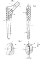
- the straight shaft 1 (FIG. 1), which consists of metal, preferably titanium or a titanium alloy, is rounded on all sides and widens conically from its distal end to the proximal end. Its cross-section is oval or elliptical-like and increases continuously from distal to proximal.
- the lateral narrow side 2 leads in an arc to a horizontal shoulder at the proximal end of the shaft, which in turn merges into the prosthesis neck 3. This carries a conical pin 4 for receiving the joint head, not shown.
- depressions 5 are worked into the “wide” sides and into the lateral narrow side 2 of the shaft 1, which depressions can be distributed regularly or irregularly on the surface of the said sides.
- the cross section of the recesses 5 is circular cylindrical for ease of manufacture;
- the not yet hardened bone cement 7 (FIG. 3a) completely fills the depressions 5. However, it shrinks during hardening, so that - as shown in a greatly exaggerated manner in FIG separates the shaft surface. Due to the circumferential surfaces 6 of the recesses 5 running perpendicular to the shaft surface, however, a step-like support remains on which the bone cement 7 can be supported in the recess 5. This support runs perpendicular to the main loading direction of the straight shaft 1 indicated by the arrow 8, so that no force component is set which forces the bone cement 7 out of the recess 5.
Abstract
Description
Die Erfindung betrifft einen geraden, allseitig abgerundeten Schaft zur Verankerung einer Gelenkendoprothese mit Hilfe von Knochenzement, welcher Schaft auf der Oberfläche mit einer Verankerungsstruktur aus einzelnen Vertiefungen versehen ist.The invention relates to a straight shaft, rounded on all sides, for anchoring a joint endoprosthesis with the aid of bone cement, which shaft is provided on the surface with an anchoring structure composed of individual depressions.
Ein Schaft wie er vorstehend beschrieben ist, ist beispielsweise für eine Hüftgelenksprothese bekannt aus der DE-PS 837 294. Die dort beschriebenen Oberflächenstrukturen bestehen unter anderem aus Längsrillen, die parallel zur Schaftachse verlaufen oder aus einzelnen Vertiefungen, die die Form von hohlen Kugelkalotten haben. Werden Schäfte mit einer derartigen Struktur mit Hilfe eines Knochenzementbettes verankert, so besteht die Gefahr von Schaftlockerungen; denn der Knochenzement ist bekanntlich einer Schwindung unterworfen, so dass er sich teilweise aus den Vertiefungen der Struktur "zurückzieht". Gegen die - bei einem geraden Schaft vor allem in Richtung der Längsachse wirkenden - Belastungskräfte sind die Längsrillen praktisch wirkungslos; sie behindern nur unerwünschte Rotationen. Aus kugelförmigen singulären Vertiefungen wird der geschwundene Zement durch die Belastungskräfte in Richtung der Schaftachse - ebenso wie aus anderen Vertiefungen mit zur Belastungsrichtung schrägen Wänden - nach aussen herausgedrückt, wodurch die bei der Implantation in den Vertiefungen des Schaftes gebildeten "Vorsprünge" des Knochenzementes leicht aus diesen Vertiefungen herausrutschen. Dies führt, besonders wegen der dauernden Wechsel zwischen Be- und Entlastungen, schliesslich zu Schaftlockeruhgen.A shaft as described above is known, for example, for a hip joint prosthesis from DE-PS 837 294. The surface structures described there consist, among other things, of longitudinal grooves which run parallel to the shaft axis or of individual depressions which have the shape of hollow spherical caps. If stems with such a structure are anchored with the aid of a bone cement bed, there is a risk of shaft loosening; as is well known, the bone cement is subject to shrinkage, so that it partially "withdraws" from the recesses in the structure. The longitudinal grooves are practically ineffective against the load forces which act on a straight shaft, especially in the direction of the longitudinal axis; they only hinder unwanted rotations. Spherical cement is transformed from spherical singular depressions by the loading forces in the direction of the shaft axis - just like from other depressions with the loading direction sloping walls - pressed outwards, as a result of which the "projections" of the bone cement formed in the recesses of the shaft during implantation slip easily out of these recesses. This leads to shaft loosening, especially because of the constant changes between loading and unloading.
Aufgabe der Erfindung ist es daher, einen Schaft der eingangs beschriebenen Art mit einer Oberflächenstruktur zu versehen, von der die Belastungen in Richtung der Längsachse auf den Knochenzement trotz seines Schwindens weitergeleitet werden, ohne dass der Zement dabei aus der Struktur herausgedrückt wird. Diese Aufgabe wird mit der Erfindung dadurch gelöst, die Vertiefungen, die mindestens im proximalen Bereich des Schaftes angeordnet sind, mit ihren Mantelflächen mindestens nahezu senkrecht zur Oberfläche des Schaftes verlaufen.The object of the invention is therefore to provide a shaft of the type described at the outset with a surface structure from which the loads in the direction of the longitudinal axis are transmitted to the bone cement despite its shrinkage, without the cement being pressed out of the structure. This object is achieved with the invention in that the depressions, which are arranged at least in the proximal region of the shaft, run with their lateral surfaces at least almost perpendicular to the surface of the shaft.
Bei einer derartigen Ausgestaltung der Vertiefungen bildet jede Vertiefung einmim wesentlichen senkrecht zur Belastungsrichtung stehenden stufenförmigen Absatz, auf dem sich auch der geschwundene Knochenzement abstützt, ohne dass ihn dabei eine nach aussen gerichtete Kraftkomponente aus der Vertiefung herausdrückt.With such a configuration of the depressions, each depression forms a step-shaped shoulder which is essentially perpendicular to the direction of loading and on which the shrunk bone cement is also supported without an outward force component pushing it out of the depression.
Wie aus Versuchen ermittelt worden ist, hat es sich als vorteilhaft erwiesen, wenn die Tiefe der Vertiefungen, also die "Stufenhöhe", absolut mindestens 1 mm beträgt, während ihre Durchmesser zweckmässigerweise das 2- bis 4-fache ihrer Tiefe betragen können.As has been determined from tests, it has proven to be advantageous if the depth of the depressions, ie the “step height”, is absolutely at least 1 mm, while their diameters can expediently be 2 to 4 times their depth.
Im folgenden wird die Erfindung anhand einer Hüftgelenksprothese als Ausführungsbeispiel im Zusammenhang mit der Zeichnung näher erläutert.
- Fig. 1 ist eine Ansicht von anterior oder posterior auf einen mit der neuen Struktur versehenen Schaft für eine Hüftgelenksprothese;
- Fig. 2 ist - teilweise im Schnitt - eine Ansicht von Fig. l von links;
- Fig. 3a und 3b gibt in stark vergrössertem Massstab ein Detail aus Fig. 2 im Schnitt wieder.
- Figure 1 is an anterior or posterior view of a new structure stem for a hip prosthesis;
- Fig. 2 is - partly in section - a view of Figure 1 from the left;
- 3a and 3b show a detail from FIG. 2 on average on a greatly enlarged scale.
Der gerade Schaft 1 (Fig. 1), der aus Metall, vorzugsweise aus Titan oder einer Titanlegierung, besteht, ist allseitig abgerundet und erweitert sich konisch von seinem distalen Ende nach proximal. Sein Querschnitt ist oval oder ellipsen- ähnlich und vergrössert sich von distal nach proximal kontinuierlich. Die laterale Schmalseite 2 führt in einem Bogen zu einer horizontalen Schulter am proximalen Schaftende, die ihrerseits in den Prothesenhals 3 übergeht. Dieser trägt einen konischen Zapfen 4 für die Aufnahme des nicht dargestellten Gelenkkopfes.The straight shaft 1 (FIG. 1), which consists of metal, preferably titanium or a titanium alloy, is rounded on all sides and widens conically from its distal end to the proximal end. Its cross-section is oval or elliptical-like and increases continuously from distal to proximal. The lateral
Im proximalen Bereich sind in die "breiten" Seiten und in die laterale Schmalseite 2 des Schaftes 1 Vertiefungen 5 eingearbeitet, die regel- oder unregelmässig auf der Oberfläche der genannten Seiten verteilt sein können. Der Querschnitt der Vertiefungen 5 ist der einfachen Herstellung wegen kreiszylindrisch; erfindungsgemäss verlaufen die Mantelflächen 6 (Fig. 3b) der Vertiefungen 5 senkrecht zur Oberfläche des Schaftes 1. Ihre Tiefe beträgt beispielsweise t = 1,5 mm (Fig. 3b).In the proximal region,
Bei der Implantation füllt der noch nicht ausgehärtete Knochenzement 7 (Fig. 3a) die Vertiefungen 5 vollständig aus. Er schwindet jedoch beim Aushärten, so dass - wie in Fig. 3b stark übertrieben dargestellt - ein "Spalt" den Knochenzement 7 von der Schaftoberfläche trennt. Aufgrund der senkrecht zur Schaftoberfläche verlaufenden Mantelflächen 6 der Vertiefungen 5 bleibt jedoch eine stufenartige Auflage erhalten, auf der sich der Knochenzement 7 in der Vertiefung 5 abstützen kann. Diese Auflage verläuft senkrecht zu der durch den Pfeil 8 angedeuteten Hauptbelastungsrichtung des Geradschaftes 1, so dass sich keine Kraftkomponente einstellt, die den Knochenzement 7 aus der Vertiefung 5 hinausdrängt.During implantation, the not yet hardened bone cement 7 (FIG. 3a) completely fills the
Claims (3)
Applications Claiming Priority (2)
| Application Number | Priority Date | Filing Date | Title |
|---|---|---|---|
| CH306485A CH666611A5 (en) | 1985-07-15 | 1985-07-15 | STRAIGHT, ROUNDED SHAFT FOR ANCHORING A HIP PROSTHETATION USING BONE CEMENT. |
| CH3064/85 | 1985-07-15 |
Publications (1)
| Publication Number | Publication Date |
|---|---|
| EP0212084A1 true EP0212084A1 (en) | 1987-03-04 |
Family
ID=4247817
Family Applications (1)
| Application Number | Title | Priority Date | Filing Date |
|---|---|---|---|
| EP86107054A Withdrawn EP0212084A1 (en) | 1985-07-15 | 1986-05-23 | Straight, totally rounded stem for anchoring a hip joint prosthesis by means of bone cement |
Country Status (2)
| Country | Link |
|---|---|
| EP (1) | EP0212084A1 (en) |
| CH (1) | CH666611A5 (en) |
Cited By (5)
| Publication number | Priority date | Publication date | Assignee | Title |
|---|---|---|---|---|
| US4978359A (en) * | 1988-04-27 | 1990-12-18 | Thera Patent Gmbh & Co. Kg Gesellschaft Fur Industrielle Schutzrechte | Prosthesis shaft |
| WO1994028827A1 (en) * | 1993-06-05 | 1994-12-22 | Depuy International Ltd. | A prosthesis component |
| FR2740026A1 (en) * | 1995-10-20 | 1997-04-25 | Jbs Sa | Hip prosthesis with cavities in femoral implant |
| FR2827155A1 (en) * | 2001-07-16 | 2003-01-17 | Biomet Merck France | Hip prosthesis femoral shank has pairs of cavities in inner face of metaphysis section |
| WO2007069250A3 (en) * | 2005-12-14 | 2007-11-01 | Presrv Ltd | Faceted long bone head prosthesis |
Families Citing this family (1)
| Publication number | Priority date | Publication date | Assignee | Title |
|---|---|---|---|---|
| EP0446559B1 (en) * | 1990-03-13 | 1993-09-01 | GebràDer Sulzer Aktiengesellschaft | Cement affixated plastic hip cup |
Citations (5)
| Publication number | Priority date | Publication date | Assignee | Title |
|---|---|---|---|---|
| US3740769A (en) * | 1971-02-11 | 1973-06-26 | E Haboush | Prosthesis for hip joints |
| AU480221B2 (en) * | 1972-09-21 | 1976-05-27 | Electro-Biology Inc. | |
| EP0106945A1 (en) * | 1982-10-15 | 1984-05-02 | GebràDer Sulzer Aktiengesellschaft | Anchoring shaft for the anchoring of bone implants |
| DE3322803A1 (en) * | 1983-06-24 | 1985-01-10 | Orthoplant Vertriebs-GmbH, 2800 Bremen | Cement-free implantable prosthesis having a grid profile |
| EP0158534A2 (en) * | 1984-04-13 | 1985-10-16 | Finsbury (Instruments) Limited | Hip implant |
-
1985
- 1985-07-15 CH CH306485A patent/CH666611A5/en not_active IP Right Cessation
-
1986
- 1986-05-23 EP EP86107054A patent/EP0212084A1/en not_active Withdrawn
Patent Citations (5)
| Publication number | Priority date | Publication date | Assignee | Title |
|---|---|---|---|---|
| US3740769A (en) * | 1971-02-11 | 1973-06-26 | E Haboush | Prosthesis for hip joints |
| AU480221B2 (en) * | 1972-09-21 | 1976-05-27 | Electro-Biology Inc. | |
| EP0106945A1 (en) * | 1982-10-15 | 1984-05-02 | GebràDer Sulzer Aktiengesellschaft | Anchoring shaft for the anchoring of bone implants |
| DE3322803A1 (en) * | 1983-06-24 | 1985-01-10 | Orthoplant Vertriebs-GmbH, 2800 Bremen | Cement-free implantable prosthesis having a grid profile |
| EP0158534A2 (en) * | 1984-04-13 | 1985-10-16 | Finsbury (Instruments) Limited | Hip implant |
Cited By (5)
| Publication number | Priority date | Publication date | Assignee | Title |
|---|---|---|---|---|
| US4978359A (en) * | 1988-04-27 | 1990-12-18 | Thera Patent Gmbh & Co. Kg Gesellschaft Fur Industrielle Schutzrechte | Prosthesis shaft |
| WO1994028827A1 (en) * | 1993-06-05 | 1994-12-22 | Depuy International Ltd. | A prosthesis component |
| FR2740026A1 (en) * | 1995-10-20 | 1997-04-25 | Jbs Sa | Hip prosthesis with cavities in femoral implant |
| FR2827155A1 (en) * | 2001-07-16 | 2003-01-17 | Biomet Merck France | Hip prosthesis femoral shank has pairs of cavities in inner face of metaphysis section |
| WO2007069250A3 (en) * | 2005-12-14 | 2007-11-01 | Presrv Ltd | Faceted long bone head prosthesis |
Also Published As
| Publication number | Publication date |
|---|---|
| CH666611A5 (en) | 1988-08-15 |
Similar Documents
| Publication | Publication Date | Title |
|---|---|---|
| EP0058745B1 (en) | Straight blade like shaft for a joint endoprosthesis | |
| EP0204919B1 (en) | Prosthesis of the head of the femur | |
| EP0106945B1 (en) | Anchoring shaft for the anchoring of bone implants | |
| EP0717609B1 (en) | Prosthesis for small joints | |
| DE2041929C3 (en) | Cup for a shoulder joint prosthesis | |
| EP0131178B1 (en) | Hip joint prosthesis with a femur anchoring shaft | |
| DE2746664C3 (en) | Anchoring shaft for a bone implant | |
| DE3710233C2 (en) | ||
| DE2724040B2 (en) | Cap-like endoprosthesis for the femoral head | |
| DE2834298C3 (en) | Femoral head cap for a hip joint prosthesis to be implanted without cement | |
| DE19731442A1 (en) | Cup for a joint endoprosthesis | |
| DE2247560B1 (en) | Hip joint head prosthesis | |
| DE2359627A1 (en) | ELBOW JOINT ENDOPROTHESIS | |
| DE3415934A1 (en) | Total endoprosthesis for a hip joint | |
| EP0142759A2 (en) | Hip joint cup | |
| DE3505997A1 (en) | Stem for a hip endoprosthesis | |
| EP0447734A1 (en) | Femoral head prosthesis for cementless affixation | |
| EP0024442A1 (en) | Composite endoprosthesis consisting of a metallic body and a ceramic joint | |
| EP0144588B1 (en) | Hip joint cup | |
| EP0119321A1 (en) | Hip joint cup | |
| EP0151724B1 (en) | Tibia part of a knee joint prosthesis | |
| EP0212084A1 (en) | Straight, totally rounded stem for anchoring a hip joint prosthesis by means of bone cement | |
| DE3426947A1 (en) | Self-adhesive, cementless implantable hip implant | |
| CH656797A5 (en) | FEMUR HEAD PROSTHESIS. | |
| DE2517702B2 (en) | Femur part of a total hip joint replacement |
Legal Events
| Date | Code | Title | Description |
|---|---|---|---|
| PUAI | Public reference made under article 153(3) epc to a published international application that has entered the european phase |
Free format text: ORIGINAL CODE: 0009012 |
|
| AK | Designated contracting states |
Kind code of ref document: A1 Designated state(s): AT DE FR GB IT |
|
| 17P | Request for examination filed |
Effective date: 19870810 |
|
| 17Q | First examination report despatched |
Effective date: 19890209 |
|
| STAA | Information on the status of an ep patent application or granted ep patent |
Free format text: STATUS: THE APPLICATION IS DEEMED TO BE WITHDRAWN |
|
| 18D | Application deemed to be withdrawn |
Effective date: 19890922 |
|
| RIN1 | Information on inventor provided before grant (corrected) |
Inventor name: SPOTORNO, LORENZO, DR.-MED. |