EP0211418A2 - Condenser laundry dryer - Google Patents
Condenser laundry dryer Download PDFInfo
- Publication number
- EP0211418A2 EP0211418A2 EP86110662A EP86110662A EP0211418A2 EP 0211418 A2 EP0211418 A2 EP 0211418A2 EP 86110662 A EP86110662 A EP 86110662A EP 86110662 A EP86110662 A EP 86110662A EP 0211418 A2 EP0211418 A2 EP 0211418A2
- Authority
- EP
- European Patent Office
- Prior art keywords
- machine
- condenser unit
- deflector element
- receptacle
- laundry dryer
- Prior art date
- Legal status (The legal status is an assumption and is not a legal conclusion. Google has not performed a legal analysis and makes no representation as to the accuracy of the status listed.)
- Granted
Links
Images


Classifications
-
- D—TEXTILES; PAPER
- D06—TREATMENT OF TEXTILES OR THE LIKE; LAUNDERING; FLEXIBLE MATERIALS NOT OTHERWISE PROVIDED FOR
- D06F—LAUNDERING, DRYING, IRONING, PRESSING OR FOLDING TEXTILE ARTICLES
- D06F58/00—Domestic laundry dryers
- D06F58/20—General details of domestic laundry dryers
- D06F58/24—Condensing arrangements
Definitions
- the present invention relates to a condenser laundry dryer, particularly of the domestic type having a rotating drum, in which the discharge flow of the cooling air of the condenser unit may selectively be directed along different discharge flowpaths from the machine, depending on the location of the. condensate collector receptacle, which in the laundry dryer according to the invention may be positioned in an upper or a lower portion of the machine.
- the condensed water is collected in a receptacle removably accommodated in the interior of the machine so that it can be emptied when the collected water attains a maximum filling level.
- the condensate collector receptacle is usually of the open-top type. In the more economic models of laundry dryers, it is usually placed directly underneath the condenser unit so as to be filled with the condensate flowing from the surfaces of the condenser by the action of gravity. In the more sophisticated models of laundry dryers, the receptacle is frequently placed at a more convenient location in an upper portion of the machine so as to be removable therefrom. In this case, the condensed water accumulates in a collector disposed below the condenser and is conveyed therefrom to the collector receptacle by means of a transfer conduit connected to a centrifugal pump.
- the two basic types of dryers are provided with different discharge flowpaths for the cooling air, resulting in an uneconomical diversification in the manufacture of dryers conforming to one or the other basic type.
- a laundry dryer of this construction would also be more readily adaptable to the composition of so-called laundering columns, in which case the laundry dryer would be placed on top of a laundry washing machine, so that, to be readily accessible, the condensate collector receptacle would necessarily have to be located in the lower portion of the machine.
- a laundry dryer having a rotatable drum, with circulation of the drying air in a closed circuit, and circulation of the condensing air in an open circuit
- said dryer being provided with a removable condensate collector receptacle and a condenser unit housed in a bcx-shaped container formed with inlet and outlet openings for the condensing air
- a deflector element mounted on the outlet opening of the box-shaped container is adapted toselectively assume one of two positions in a first of which it cooperates with the walls of the dryer and with baffles integrally formed with the box-shaped container to form a conduit for the discharge of the condensing air to the exterior, and in the second of which it forms a partition defining a chamber for the accomodation of the removable receptacle below the condenser unit, and simultaneously establishes communication of the condenser unit with the interior of the housing of the dryer.
- the laundry dryer 10 is of the type having a rotatable drum (not shown) and includes an air-cooled condenser unit 11 housed in a box-shaped container 12 fixedly mounted in a lower portion of the dryer.
- the cooling air for condenser unit 11 is aspirated by means of a fan 13 through an opening 14 formed in a bottom portion 15 of a front wall 30 of the dryer.
- the intericr rim of opening 14 is extended towards the interior of the machine so as to permit the respective part of bottom portion 15 to be received in a connector element 16 to thus define a flowpath for the air aspirated by fan 13.
- Fan 13 is rotated by a motor 17 of the machine so as to convey the aspirated air through the drying air condenser unit 11 and to expel it from box-shaped housing 12 through at least one outlet opening 18 formed in the housing opposite an inlet opening 19 thereof.
- Box-shaped housing 12 is integrally formed with a lower baffle 20 delimiting an area below condenser unit 11. Adjacent the side of the machine baffle 20 is upwards extended by a lateral baffle 21. Baffles 20 and 21 and the bottom of box-shaped container 12 cooperate with the bottom 22 of the machine to define a chamber 31 communicating with the remainder of the dryer 10 through a passage 24 (fig. 3) extending between cooling air outlet opening 18 and a sidewall 23 of the machine 10.
- the above described machine is adapted to accommodate a condensate collector receptacle 25 selectively in chamber 31 underneath condenser unit 11 (figs. 3, 6) or in an upper portion of dryer 10, as diagrammatically shown in fig. 2.
- a deflector element 26 having a substantially L-shaped cross-section and extending over the full length of opening 18 between front wall 30 of the machine and lateral baffle 21 of box-shaped container 12.
- Deflector element 26 may be secured to the upper boundary of outlet opening 18 by means of threaded fasteners or in a snap fit, and in engagement with the adjacent sidewall 23 of the machine, as shown in fig. 2, so as to deflect the cooling air towards chamber 31 underneath container 12, from where the air escapes to the exterior of machine 10 through openings 27 in the base of the housing.
- This solution offers the additional advantage that the cooling air escaping from condenser unit 11 at a temperature which is always lower than that of the drying drum is prevented from sweeping the walls of the drum and from thereby impairing the efficiency of the drying process, instead of which it is directly discharged from the machine.
- deflector element 26 For obtaining a laundry dryer with receptacle 25 accommodated in chamber 31, the same deflector element 26 is secured to the lower rim of outlet opening 18 and in contact with sidewall 23 of the machine in the position depicted in fig. 3. In this position, deflector element 26 deflects the air escaping from outlet opening 18 upwards into the free space in the interior of the machine, from which it escapes through openings 28 formed in the rear wall 29 of the machine.
- the dryer has of course to be provided with the known components required for its operation in the respective configuration.
- box-shaped container 12 with a lower opening (not shown in the drawings), which in the configuration with receptacle 25 in the lower position permits the condensate to flow into a hopper 40 communicating with receptacle 25 (figs. 3, 6).
Abstract
Description
- The present invention relates to a condenser laundry dryer, particularly of the domestic type having a rotating drum, in which the discharge flow of the cooling air of the condenser unit may selectively be directed along different discharge flowpaths from the machine, depending on the location of the. condensate collector receptacle, which in the laundry dryer according to the invention may be positioned in an upper or a lower portion of the machine.
- In known condenser laundry dryers, the condensed water is collected in a receptacle removably accommodated in the interior of the machine so that it can be emptied when the collected water attains a maximum filling level.
- The condensate collector receptacle is usually of the open-top type. In the more economic models of laundry dryers, it is usually placed directly underneath the condenser unit so as to be filled with the condensate flowing from the surfaces of the condenser by the action of gravity. In the more sophisticated models of laundry dryers, the receptacle is frequently placed at a more convenient location in an upper portion of the machine so as to be removable therefrom. In this case, the condensed water accumulates in a collector disposed below the condenser and is conveyed therefrom to the collector receptacle by means of a transfer conduit connected to a centrifugal pump.
- The positioning of the condensate collector receptacle sometimes in the lower portion and sometimes in the upper portion of the machine has finally resulted in the construction of functionally and structurally widely different laundry dryers.
- In addition to requiring different indispensable components, such as the transfer conduit with the associated centrifugal pump, the two basic types of dryers are provided with different discharge flowpaths for the cooling air, resulting in an uneconomical diversification in the manufacture of dryers conforming to one or the other basic type.
- It would thus be advantageous, and is therefore an object of the invention, to provide a laundry dryer the construction of which is standardized as far as possible for the two basic types of dryers for thus enabling the condensate collector receptacle to be selectively positioned in a lower portion or an upper portion of the machine, so that the desired dryer model can be obtained by carrying out simple modifications during the final stage of assembly.
- A laundry dryer of this construction would also be more readily adaptable to the composition of so-called laundering columns, in which case the laundry dryer would be placed on top of a laundry washing machine, so that, to be readily accessible, the condensate collector receptacle would necessarily have to be located in the lower portion of the machine.
- These objects are attained according to the invention in a laundry dryer having a rotatable drum, with circulation of the drying air in a closed circuit, and circulation of the condensing air in an open circuit, said dryer being provided with a removable condensate collector receptacle and a condenser unit housed in a bcx-shaped container formed with inlet and outlet openings for the condensing air, wherein a deflector element mounted on the outlet opening of the box-shaped container is adapted toselectively assume one of two positions in a first of which it cooperates with the walls of the dryer and with baffles integrally formed with the box-shaped container to form a conduit for the discharge of the condensing air to the exterior, and in the second of which it forms a partition defining a chamber for the accomodation of the removable receptacle below the condenser unit, and simultaneously establishes communication of the condenser unit with the interior of the housing of the dryer.
- The characteristics and advantages of the invention will become more clearly evident from the following description, given by way of example with reference to the accompanying drawings, wherein:
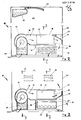
- fig. 1 shows a cross-sectional view of the laundry dryer according to the invention,
- figs. 2 and 3 show longitudinal sectional views of the laundry dryer of fig. 1 with a condensate collector receptacle accommodated respectively in an upper portion and a lower portion of the dryer,
- fig. 4 shows a sectional view taken along the line IV-IV in fig. 3, and
- figs. 5 and 6 show sectional views of the dryer taken respectively along the lines V-V and VI-VI in figs. 2 and 3.
- The
laundry dryer 10 according to the invention is of the type having a rotatable drum (not shown) and includes an air-cooledcondenser unit 11 housed in a box-shaped container 12 fixedly mounted in a lower portion of the dryer. - The cooling air for
condenser unit 11 is aspirated by means of afan 13 through an opening 14 formed in abottom portion 15 of afront wall 30 of the dryer. - The intericr rim of
opening 14 is extended towards the interior of the machine so as to permit the respective part ofbottom portion 15 to be received in aconnector element 16 to thus define a flowpath for the air aspirated byfan 13.Fan 13 is rotated by amotor 17 of the machine so as to convey the aspirated air through the dryingair condenser unit 11 and to expel it from box-shaped housing 12 through at least one outlet opening 18 formed in the housing opposite an inlet opening 19 thereof. - Box-
shaped housing 12 is integrally formed with alower baffle 20 delimiting an area belowcondenser unit 11. Adjacent the side of themachine baffle 20 is upwards extended by alateral baffle 21.Baffles shaped container 12 cooperate with thebottom 22 of the machine to define achamber 31 communicating with the remainder of thedryer 10 through a passage 24 (fig. 3) extending between cooling air outlet opening 18 and asidewall 23 of themachine 10. - The above described machine is adapted to accommodate a
condensate collector receptacle 25 selectively inchamber 31 underneath condenser unit 11 (figs. 3, 6) or in an upper portion ofdryer 10, as diagrammatically shown in fig. 2. - For preparing the machine to the configuration with receptacle in the upper position, provisions are made for the application to cooling air outlet opening 18 of a
deflector element 26 having a substantially L-shaped cross-section and extending over the full length of opening 18 betweenfront wall 30 of the machine andlateral baffle 21 of box-shaped container 12.Deflector element 26 may be secured to the upper boundary of outlet opening 18 by means of threaded fasteners or in a snap fit, and in engagement with theadjacent sidewall 23 of the machine, as shown in fig. 2, so as to deflect the cooling air towardschamber 31 underneathcontainer 12, from where the air escapes to the exterior ofmachine 10 throughopenings 27 in the base of the housing. This solution offers the additional advantage that the cooling air escaping fromcondenser unit 11 at a temperature which is always lower than that of the drying drum is prevented from sweeping the walls of the drum and from thereby impairing the efficiency of the drying process, instead of which it is directly discharged from the machine. - For obtaining a laundry dryer with
receptacle 25 accommodated inchamber 31, thesame deflector element 26 is secured to the lower rim of outlet opening 18 and in contact withsidewall 23 of the machine in the position depicted in fig. 3. In this position,deflector element 26 deflects the air escaping from outlet opening 18 upwards into the free space in the interior of the machine, from which it escapes throughopenings 28 formed in therear wall 29 of the machine. - There is thus attained the main object of providing a
laundry dryer 10 the construstion of which is standardized as far as possible with a view to the accommodation of thecondensate collector receptacle 25 in the two positions by simply repositioningdeflector element 26 to obtain the desired dryer model. - Depending on the positioning of
deflector element 26 andcollector receptacle 25, the dryer has of course to be provided with the known components required for its operation in the respective configuration. - It is for instance known to provide box-
shaped container 12 with a lower opening (not shown in the drawings), which in the configuration withreceptacle 25 in the lower position permits the condensate to flow into ahopper 40 communicating with receptacle 25 (figs. 3, 6). - In the configuration with
receptacle 25 in the upper position, on the other hand, provisions are made for the addition of a pump (not shown) for the transfer of the liquid fromhopper 40 to receptacle 25 via a transfer conduit 41 (figs. 2, 5).
Claims (4)
Priority Applications (1)
| Application Number | Priority Date | Filing Date | Title |
|---|---|---|---|
| AT86110662T ATE62285T1 (en) | 1985-08-02 | 1986-08-01 | FLAT DRYER WITH CONDENSATION DEVICE. |
Applications Claiming Priority (2)
| Application Number | Priority Date | Filing Date | Title |
|---|---|---|---|
| IT3405285U | 1985-08-02 | ||
| IT8534052U IT209164Z2 (en) | 1985-08-02 | 1985-08-02 | CONDENSATION DRYER. |
Publications (3)
| Publication Number | Publication Date |
|---|---|
| EP0211418A2 true EP0211418A2 (en) | 1987-02-25 |
| EP0211418A3 EP0211418A3 (en) | 1988-01-27 |
| EP0211418B1 EP0211418B1 (en) | 1991-04-03 |
Family
ID=11239054
Family Applications (1)
| Application Number | Title | Priority Date | Filing Date |
|---|---|---|---|
| EP86110662A Expired - Lifetime EP0211418B1 (en) | 1985-08-02 | 1986-08-01 | Condenser laundry dryer |
Country Status (4)
| Country | Link |
|---|---|
| EP (1) | EP0211418B1 (en) |
| AT (1) | ATE62285T1 (en) |
| DE (1) | DE3678506D1 (en) |
| IT (1) | IT209164Z2 (en) |
Cited By (9)
| Publication number | Priority date | Publication date | Assignee | Title |
|---|---|---|---|---|
| FR2694578A1 (en) * | 1992-08-05 | 1994-02-11 | Bosch Siemens Hausgeraete | Tumble dryer with condenser unit. |
| EP1108811A1 (en) * | 1999-12-14 | 2001-06-20 | Whirlpool Corporation | Condensation tumble dryer with heat exchanger and condensate collecting device |
| EP1508636A2 (en) * | 2003-08-13 | 2005-02-23 | Lg Electronics Inc. | Apparatus for suctioning external air of clothes dryer |
| EP1555342A2 (en) * | 2003-12-19 | 2005-07-20 | Lg Electronics Inc. | A laundry dryer and an air inlet structure thereof |
| GB2434160A (en) * | 2006-01-12 | 2007-07-18 | Dyson Technology Ltd | Drying apparatus |
| EP2458074A1 (en) * | 2010-11-29 | 2012-05-30 | Electrolux Home Products Corporation N.V. | Heat pump laundry dryer |
| EP2169106A3 (en) * | 2008-09-26 | 2015-10-21 | BSH Hausgeräte GmbH | Household clothes drying device |
| US9273903B2 (en) | 2010-11-29 | 2016-03-01 | Electrolux Home Products Corporation N.V. | Laundry dryer |
| EP3234254A1 (en) * | 2014-12-16 | 2017-10-25 | Electrolux Appliances Aktiebolag | Laundry treatment apparatus having a heat exchanger and a condensate collector |
Families Citing this family (4)
| Publication number | Priority date | Publication date | Assignee | Title |
|---|---|---|---|---|
| GB0515754D0 (en) | 2005-07-30 | 2005-09-07 | Dyson Technology Ltd | Drying apparatus |
| GB0515750D0 (en) | 2005-07-30 | 2005-09-07 | Dyson Technology Ltd | Drying apparatus |
| GB2428569B (en) | 2005-07-30 | 2009-04-29 | Dyson Technology Ltd | Dryer |
| GB2434094A (en) | 2006-01-12 | 2007-07-18 | Dyson Technology Ltd | Drying apparatus with sound-absorbing material |
Citations (4)
| Publication number | Priority date | Publication date | Assignee | Title |
|---|---|---|---|---|
| US2742708A (en) * | 1952-07-12 | 1956-04-24 | Gen Motors Corp | Domestic appliance |
| FR2486220A1 (en) * | 1980-07-04 | 1982-01-08 | Sueddeutsche Kuehler Behr | Air-cooled condensation drier for laundry - uses plate heat exchanger with cross-currents |
| GB2105452A (en) * | 1981-08-08 | 1983-03-23 | Bauknecht Gmbh G | Laundry dryer |
| GB2115126A (en) * | 1982-02-09 | 1983-09-01 | Bosch Siemens Hausgeraete | Household laundry drier with condensate collection |
-
1985
- 1985-08-02 IT IT8534052U patent/IT209164Z2/en active
-
1986
- 1986-08-01 EP EP86110662A patent/EP0211418B1/en not_active Expired - Lifetime
- 1986-08-01 AT AT86110662T patent/ATE62285T1/en active
- 1986-08-01 DE DE8686110662T patent/DE3678506D1/en not_active Expired - Fee Related
Patent Citations (4)
| Publication number | Priority date | Publication date | Assignee | Title |
|---|---|---|---|---|
| US2742708A (en) * | 1952-07-12 | 1956-04-24 | Gen Motors Corp | Domestic appliance |
| FR2486220A1 (en) * | 1980-07-04 | 1982-01-08 | Sueddeutsche Kuehler Behr | Air-cooled condensation drier for laundry - uses plate heat exchanger with cross-currents |
| GB2105452A (en) * | 1981-08-08 | 1983-03-23 | Bauknecht Gmbh G | Laundry dryer |
| GB2115126A (en) * | 1982-02-09 | 1983-09-01 | Bosch Siemens Hausgeraete | Household laundry drier with condensate collection |
Cited By (14)
| Publication number | Priority date | Publication date | Assignee | Title |
|---|---|---|---|---|
| FR2694578A1 (en) * | 1992-08-05 | 1994-02-11 | Bosch Siemens Hausgeraete | Tumble dryer with condenser unit. |
| EP1108811A1 (en) * | 1999-12-14 | 2001-06-20 | Whirlpool Corporation | Condensation tumble dryer with heat exchanger and condensate collecting device |
| EP1508636A3 (en) * | 2003-08-13 | 2006-10-04 | Lg Electronics Inc. | Apparatus for suctioning external air of clothes dryer |
| EP1508636A2 (en) * | 2003-08-13 | 2005-02-23 | Lg Electronics Inc. | Apparatus for suctioning external air of clothes dryer |
| EP1555342A3 (en) * | 2003-12-19 | 2013-11-20 | LG Electronics, Inc. | A laundry dryer and an air inlet structure thereof |
| EP1555342A2 (en) * | 2003-12-19 | 2005-07-20 | Lg Electronics Inc. | A laundry dryer and an air inlet structure thereof |
| GB2434160A (en) * | 2006-01-12 | 2007-07-18 | Dyson Technology Ltd | Drying apparatus |
| US7856736B2 (en) | 2006-01-12 | 2010-12-28 | Dyson Technology Limited | Drying apparatus |
| EP2169106A3 (en) * | 2008-09-26 | 2015-10-21 | BSH Hausgeräte GmbH | Household clothes drying device |
| EP2458074A1 (en) * | 2010-11-29 | 2012-05-30 | Electrolux Home Products Corporation N.V. | Heat pump laundry dryer |
| WO2012072485A3 (en) * | 2010-11-29 | 2012-07-26 | Electrolux Home Products Corporation N.V. | Heat pump laundry dryer |
| US9273903B2 (en) | 2010-11-29 | 2016-03-01 | Electrolux Home Products Corporation N.V. | Laundry dryer |
| EP3234254A1 (en) * | 2014-12-16 | 2017-10-25 | Electrolux Appliances Aktiebolag | Laundry treatment apparatus having a heat exchanger and a condensate collector |
| EP3234254B1 (en) * | 2014-12-16 | 2023-06-07 | Electrolux Appliances Aktiebolag | Laundry treatment apparatus having a heat exchanger and a condensate collector |
Also Published As
| Publication number | Publication date |
|---|---|
| EP0211418B1 (en) | 1991-04-03 |
| DE3678506D1 (en) | 1991-05-08 |
| IT8534052V0 (en) | 1985-08-02 |
| EP0211418A3 (en) | 1988-01-27 |
| ATE62285T1 (en) | 1991-04-15 |
| IT209164Z2 (en) | 1988-09-16 |
Similar Documents
| Publication | Publication Date | Title |
|---|---|---|
| EP0211418B1 (en) | Condenser laundry dryer | |
| EP0816549B1 (en) | Domestic washing machine having a closed drying circuit, air condensation of vapour and self cleaning filter | |
| KR100409241B1 (en) | Automatic Drying Washing Machine | |
| US4142270A (en) | Wet-dry vacuum cleaner baffle strainer system | |
| EP1612318B1 (en) | Moisture condensing unit | |
| US2892335A (en) | Laundry machine with forced air circulation system | |
| US5509283A (en) | Clothes washer having water recirculation system | |
| US5226203A (en) | Process for the cleaning of a drying condenser in clothes dryer | |
| EP0240911B1 (en) | Filter for a laundry washing machine | |
| US2664646A (en) | Drying apparatus | |
| RU95117707A (en) | AUTOMATED DRYING, WASHING MACHINE | |
| EP0252323B1 (en) | Combined laundry washing and drying machine | |
| JPH03195531A (en) | Disposition for dish washer | |
| EP0132884A2 (en) | Device for suppressing steam in domestic washing machines | |
| EP0552843B1 (en) | Washing and drying machine with an improved safety device against water pollution | |
| US2873537A (en) | Combination washer and dryer with condenser means | |
| EP0382692B1 (en) | Drain device for a dish-washer | |
| US3220230A (en) | Washer and dryer with means in the washer for removing lint from the dryer | |
| EP0045288B1 (en) | Laundry drying machine | |
| EP2163181A1 (en) | Hood-type industrial dishwasher with improved drying circuit | |
| EP0250870A2 (en) | Combined machine for washing and drying laundry | |
| EP0125627B1 (en) | Detergent supply unit for a laundry washing machine | |
| GB2223240A (en) | Washer/drier | |
| EP0493065B1 (en) | Air flow control for a dishwasher | |
| EP0402331B1 (en) | Device for a level sensor for household appliances |
Legal Events
| Date | Code | Title | Description |
|---|---|---|---|
| PUAI | Public reference made under article 153(3) epc to a published international application that has entered the european phase |
Free format text: ORIGINAL CODE: 0009012 |
|
| AK | Designated contracting states |
Kind code of ref document: A2 Designated state(s): AT BE CH DE FR GB IT LI LU NL SE |
|
| PUAL | Search report despatched |
Free format text: ORIGINAL CODE: 0009013 |
|
| RAP1 | Party data changed (applicant data changed or rights of an application transferred) |
Owner name: INDUSTRIE ZANUSSI S.P.A. |
|
| AK | Designated contracting states |
Kind code of ref document: A3 Designated state(s): AT BE CH DE FR GB IT LI LU NL SE |
|
| 17P | Request for examination filed |
Effective date: 19880610 |
|
| 17Q | First examination report despatched |
Effective date: 19900717 |
|
| ITF | It: translation for a ep patent filed |
Owner name: PROPRIA PROTEZIONE PROPR. IND. |
|
| GRAA | (expected) grant |
Free format text: ORIGINAL CODE: 0009210 |
|
| AK | Designated contracting states |
Kind code of ref document: B1 Designated state(s): AT BE CH DE FR GB IT LI LU NL SE |
|
| REF | Corresponds to: |
Ref document number: 62285 Country of ref document: AT Date of ref document: 19910415 Kind code of ref document: T |
|
| ET | Fr: translation filed | ||
| REF | Corresponds to: |
Ref document number: 3678506 Country of ref document: DE Date of ref document: 19910508 |
|
| PG25 | Lapsed in a contracting state [announced via postgrant information from national office to epo] |
Ref country code: AT Effective date: 19910801 |
|
| PG25 | Lapsed in a contracting state [announced via postgrant information from national office to epo] |
Ref country code: LU Free format text: LAPSE BECAUSE OF NON-PAYMENT OF DUE FEES Effective date: 19910831 Ref country code: LI Effective date: 19910831 Ref country code: CH Effective date: 19910831 Ref country code: BE Effective date: 19910831 |
|
| PLBE | No opposition filed within time limit |
Free format text: ORIGINAL CODE: 0009261 |
|
| STAA | Information on the status of an ep patent application or granted ep patent |
Free format text: STATUS: NO OPPOSITION FILED WITHIN TIME LIMIT |
|
| BERE | Be: lapsed |
Owner name: INDUSTRIE ZANUSSI S.P.A. Effective date: 19910831 |
|
| 26N | No opposition filed | ||
| REG | Reference to a national code |
Ref country code: CH Ref legal event code: PL |
|
| EAL | Se: european patent in force in sweden |
Ref document number: 86110662.3 |
|
| REG | Reference to a national code |
Ref country code: GB Ref legal event code: IF02 |
|
| PGFP | Annual fee paid to national office [announced via postgrant information from national office to epo] |
Ref country code: FR Payment date: 20020708 Year of fee payment: 17 |
|
| PGFP | Annual fee paid to national office [announced via postgrant information from national office to epo] |
Ref country code: GB Payment date: 20020712 Year of fee payment: 17 |
|
| PGFP | Annual fee paid to national office [announced via postgrant information from national office to epo] |
Ref country code: SE Payment date: 20020715 Year of fee payment: 17 Ref country code: NL Payment date: 20020715 Year of fee payment: 17 |
|
| PGFP | Annual fee paid to national office [announced via postgrant information from national office to epo] |
Ref country code: DE Payment date: 20020724 Year of fee payment: 17 |
|
| PG25 | Lapsed in a contracting state [announced via postgrant information from national office to epo] |
Ref country code: GB Free format text: LAPSE BECAUSE OF NON-PAYMENT OF DUE FEES Effective date: 20030801 |
|
| PG25 | Lapsed in a contracting state [announced via postgrant information from national office to epo] |
Ref country code: SE Free format text: LAPSE BECAUSE OF NON-PAYMENT OF DUE FEES Effective date: 20030802 |
|
| PG25 | Lapsed in a contracting state [announced via postgrant information from national office to epo] |
Ref country code: NL Free format text: LAPSE BECAUSE OF NON-PAYMENT OF DUE FEES Effective date: 20040301 |
|
| PG25 | Lapsed in a contracting state [announced via postgrant information from national office to epo] |
Ref country code: DE Free format text: LAPSE BECAUSE OF NON-PAYMENT OF DUE FEES Effective date: 20040302 |
|
| GBPC | Gb: european patent ceased through non-payment of renewal fee |
Effective date: 20030801 |
|
| EUG | Se: european patent has lapsed | ||
| PG25 | Lapsed in a contracting state [announced via postgrant information from national office to epo] |
Ref country code: FR Free format text: LAPSE BECAUSE OF NON-PAYMENT OF DUE FEES Effective date: 20040430 |
|
| NLV4 | Nl: lapsed or anulled due to non-payment of the annual fee |
Effective date: 20040301 |
|
| REG | Reference to a national code |
Ref country code: FR Ref legal event code: ST |
|
| PG25 | Lapsed in a contracting state [announced via postgrant information from national office to epo] |
Ref country code: IT Free format text: LAPSE BECAUSE OF NON-PAYMENT OF DUE FEES;WARNING: LAPSES OF ITALIAN PATENTS WITH EFFECTIVE DATE BEFORE 2007 MAY HAVE OCCURRED AT ANY TIME BEFORE 2007. THE CORRECT EFFECTIVE DATE MAY BE DIFFERENT FROM THE ONE RECORDED. Effective date: 20050801 |