EP0208338A2 - Induction heating apparatus - Google Patents
Induction heating apparatus Download PDFInfo
- Publication number
- EP0208338A2 EP0208338A2 EP86111207A EP86111207A EP0208338A2 EP 0208338 A2 EP0208338 A2 EP 0208338A2 EP 86111207 A EP86111207 A EP 86111207A EP 86111207 A EP86111207 A EP 86111207A EP 0208338 A2 EP0208338 A2 EP 0208338A2
- Authority
- EP
- European Patent Office
- Prior art keywords
- coil
- induction heating
- alternating current
- heating
- passing
- Prior art date
- Legal status (The legal status is an assumption and is not a legal conclusion. Google has not performed a legal analysis and makes no representation as to the accuracy of the status listed.)
- Withdrawn
Links
- 238000010438 heat treatment Methods 0.000 title claims abstract description 72
- 230000006698 induction Effects 0.000 title claims abstract description 32
- 239000004020 conductor Substances 0.000 claims description 15
- 239000003990 capacitor Substances 0.000 claims description 10
- 239000002826 coolant Substances 0.000 claims description 3
- 239000012530 fluid Substances 0.000 claims 1
- 239000007788 liquid Substances 0.000 claims 1
- 230000017074 necrotic cell death Effects 0.000 description 16
- 206010028980 Neoplasm Diseases 0.000 description 14
- 230000005291 magnetic effect Effects 0.000 description 11
- 206010020843 Hyperthermia Diseases 0.000 description 9
- 230000036031 hyperthermia Effects 0.000 description 9
- 239000000463 material Substances 0.000 description 8
- 238000011282 treatment Methods 0.000 description 7
- 239000000203 mixture Substances 0.000 description 6
- 208000035269 cancer or benign tumor Diseases 0.000 description 4
- 230000000694 effects Effects 0.000 description 4
- 239000006249 magnetic particle Substances 0.000 description 4
- 230000005855 radiation Effects 0.000 description 4
- 239000000110 cooling liquid Substances 0.000 description 3
- 230000001419 dependent effect Effects 0.000 description 3
- 230000012010 growth Effects 0.000 description 3
- 238000000034 method Methods 0.000 description 3
- 230000001613 neoplastic effect Effects 0.000 description 3
- XEEYBQQBJWHFJM-UHFFFAOYSA-N Iron Chemical compound [Fe] XEEYBQQBJWHFJM-UHFFFAOYSA-N 0.000 description 2
- 241001465754 Metazoa Species 0.000 description 2
- 230000001594 aberrant effect Effects 0.000 description 2
- 230000001747 exhibiting effect Effects 0.000 description 2
- 239000000696 magnetic material Substances 0.000 description 2
- 230000007246 mechanism Effects 0.000 description 2
- 239000002245 particle Substances 0.000 description 2
- 230000035515 penetration Effects 0.000 description 2
- XLYOFNOQVPJJNP-UHFFFAOYSA-N water Substances O XLYOFNOQVPJJNP-UHFFFAOYSA-N 0.000 description 2
- 229910000831 Steel Inorganic materials 0.000 description 1
- 208000027418 Wounds and injury Diseases 0.000 description 1
- 239000000853 adhesive Substances 0.000 description 1
- 230000001070 adhesive effect Effects 0.000 description 1
- 230000004888 barrier function Effects 0.000 description 1
- 230000008859 change Effects 0.000 description 1
- 238000006243 chemical reaction Methods 0.000 description 1
- 230000002860 competitive effect Effects 0.000 description 1
- 239000012141 concentrate Substances 0.000 description 1
- 239000012809 cooling fluid Substances 0.000 description 1
- 239000012153 distilled water Substances 0.000 description 1
- 230000005670 electromagnetic radiation Effects 0.000 description 1
- 230000005284 excitation Effects 0.000 description 1
- 230000005294 ferromagnetic effect Effects 0.000 description 1
- 230000004907 flux Effects 0.000 description 1
- 238000002513 implantation Methods 0.000 description 1
- 238000009413 insulation Methods 0.000 description 1
- 239000012212 insulator Substances 0.000 description 1
- 229910052742 iron Inorganic materials 0.000 description 1
- 238000002844 melting Methods 0.000 description 1
- 230000008018 melting Effects 0.000 description 1
- 230000002503 metabolic effect Effects 0.000 description 1
- 230000004060 metabolic process Effects 0.000 description 1
- 238000013021 overheating Methods 0.000 description 1
- 230000035699 permeability Effects 0.000 description 1
- 229920000642 polymer Polymers 0.000 description 1
- 239000000843 powder Substances 0.000 description 1
- 231100000241 scar Toxicity 0.000 description 1
- 239000010959 steel Substances 0.000 description 1
- 238000009834 vaporization Methods 0.000 description 1
- 229920002554 vinyl polymer Polymers 0.000 description 1
- 229910000859 α-Fe Inorganic materials 0.000 description 1
Images
Classifications
-
- A—HUMAN NECESSITIES
- A61—MEDICAL OR VETERINARY SCIENCE; HYGIENE
- A61K—PREPARATIONS FOR MEDICAL, DENTAL OR TOILETRY PURPOSES
- A61K9/00—Medicinal preparations characterised by special physical form
- A61K9/48—Preparations in capsules, e.g. of gelatin, of chocolate
- A61K9/50—Microcapsules having a gas, liquid or semi-solid filling; Solid microparticles or pellets surrounded by a distinct coating layer, e.g. coated microspheres, coated drug crystals
- A61K9/5094—Microcapsules containing magnetic carrier material, e.g. ferrite for drug targeting
-
- A—HUMAN NECESSITIES
- A61—MEDICAL OR VETERINARY SCIENCE; HYGIENE
- A61K—PREPARATIONS FOR MEDICAL, DENTAL OR TOILETRY PURPOSES
- A61K41/00—Medicinal preparations obtained by treating materials with wave energy or particle radiation ; Therapies using these preparations
- A61K41/0052—Thermotherapy; Hyperthermia; Magnetic induction; Induction heating therapy
-
- A—HUMAN NECESSITIES
- A61—MEDICAL OR VETERINARY SCIENCE; HYGIENE
- A61N—ELECTROTHERAPY; MAGNETOTHERAPY; RADIATION THERAPY; ULTRASOUND THERAPY
- A61N1/00—Electrotherapy; Circuits therefor
- A61N1/40—Applying electric fields by inductive or capacitive coupling ; Applying radio-frequency signals
- A61N1/403—Applying electric fields by inductive or capacitive coupling ; Applying radio-frequency signals for thermotherapy, e.g. hyperthermia
- A61N1/406—Applying electric fields by inductive or capacitive coupling ; Applying radio-frequency signals for thermotherapy, e.g. hyperthermia using implantable thermoseeds or injected particles for localized hyperthermia
Definitions
- the present invention is concerned with an induction heating apparatus which is particularly suitable for use in the treatment of neoplasms by hyperthermal necrosis.
- a radio frequency or microwave field only causes heating at or adjacent to the surface of a body because of the tendency of the body to absorb radio frequency electromagnetic radiation (the depth to which such radiation penetrates the body depends upon the frequency of the radiation).
- Such body tissue heating as is caused by radio frequency radiation has two principal components: eddy current heating and dielectric heating. Heating of this type can be achieved in the absence of any foreign material in the tissue being heated.
- hysteresis heating Induction heating of body tissue as a result of the presence of a material having hysteresis characteristics (referred to as hysteresis heating) involves the application of a magnetic field which is generally unattenuated by tissue. Hence, induction heating can reach any desired depth or level beneath the surface of the tissue. In order to achieve this manner of heating in tissue, it is necessary to locate a material exhibiting magnetic hysteresis close to the site where the heat is required.
- the term "hysteresis composition” is used hereinafter to describe a composition suitable for introducing such a material into the body. A preferred hysteresis composition for use with the apparatus of the present invention is described in European Patent Application No. 82300125.0.
- Induction-hysteresis heating is generally accompanied by some eddy current and dielectric heating, but the amount of eddy current and dielectric heating can be minimized by using a comparatively low frequency alternating magnetic field.
- the amount of such heating varies directly with the square of the frequency of the field, while the amount of hysteresis heating varies directly with the frequency.
- the lower the frequency of the field the less undesired eddy current heating relative to the amount of the desired hysteresis heating. (The frequency, of course, should be sufficiently high to ensure the desired degree of hysteresis heating).
- radio frequency heating can not be utilized effectively in causing hyperthermia in aberrant growths which are so far beneath the surface of tissue that they are not reached by the radio frequency field.
- the use of such a field to cause hyperthermia at or adjacent to the surface of the skin or at or adjacent to the interior of an incision within the body is limited by another important factor - the problem of selectively concentrating the heat so that neoplasm is heated sufficiently to cause necrosis without related or corresponding heating of adjacent normal tissue.
- the time necessary to cause necrosis at a given temperature is not directly dependent on the temperature in the usual manner of temperature-dependent reactions; in addition, certain parts of the body or neoplasms are more susceptible to necrosis at an elevated temperature than other parts of the body and/or other neoplasms. Because of these factors, it is impossible to give exact relationships between the time and the temperature necessary to accomplish necrosis of neoplasms. Another factor which is important in considering the amount of hyperthermia to cause necrosis in neoplasm is the tendency of the body and/or a particular portion of the body to serve as a heat insulator which tends to concentrate heat developed, for example, at a specific source.
- radio frequency or microwave hyperthermia With radio frequency or microwave hyperthermia, the difficulty in confining the field necessary to cause necrosis of a specific area or region will normally cause necrosis of healthy tissue in an adjacent area or region. While to a degree this can be counteracted by the use of special electrodes, it is impossible to adequately control radio frequency or microwave heating in many applications so as to avoid damage to adjacent normal cells or tissue. While it may be possible to improve the concentration of the heating effects achieved with radio frequency or microwave heating by the implantation of a metallic conductor or another similar material in a specific area where concentrated heating is desired, the use of a conductor is not always advantageous because it does not improve the depth of penetration of tissue by the radio frequency field.
- induction heating in causing necrosis of neoplasm alleviates several problems involved in radio frequency hyperthermia treatment.
- induction heating it is necessary to utilize an invasive technique to locate a material having a magnetic permeability greater than unity and capable of exhibiting hysteresis losses, for example, ferromagnetic particles such as a conventional ferrite or conventional iron or steel powders, in or immediately adjacent to the neoplastic growth.
- the application of an alternating magnetic field results in hysteresis heating within the magnetic material itself, which avoids the problem of containing or limiting the heated area obtained which arises when using a radio frequency field. Because of the penetration of low frequency magnetic fields into body tissue, it is possible to use a magnetic material well beneath the surface of the body.
- an induction heating apparatus which comprises an induction heating coil and means for passing an alternating current through the coil to cause induction heating therein, characterised in that at least one further coil is provided adjacent and in axial alignment with the heating coil, the or each further coil beinc electrically isolated from the means for passing an alternating current and being connected to form a resonant circuit arranged to resonate when alternating current passes through the heating coil thereby to provide additional induction heating.
- the apparatus of the invention can be easily and conveniently constructed at relatively low cost.
- apparatus 10 comprises a series of coaxial, identically constructed and dimensioned flat coils 12, 12'.
- Each of these coils 12, 12' consists of a series of turns (not separately numbered) of an electrically non-conductive tube 14 such as an extruded polyvinyl polymer tube located in two flat, parallel planes and a conductor 16 going through the interior of each tube 14.
- These conductors 16 are typically multi-stranded wires which are sufficiently small in diameter to permit a cooling liquid such as, for example, a dielectric oil or distilled water to be circulated through the tubes 14 around the conductors 16.
- Appropriate conventional fittings 18 are provided at the ends (not separately numbered) of the tubes 14 for the purpose of joining the ends of the tubes 14 to manifolds or distributing pipes 20 used in connection with a coolant storage reservoir 22 and a pump 24. These fittings 18 are formed in a conventional or known manner so that the conductors 16 extend through them so that these conductors 16 may be connected as hereinafter indicated.
- each conductor 16 constitutes the electrically "active" part of a coil 12, 12' and is connected into a tank circuit 26 across two separate capacitors 28 of equal capacitance value located in series with one another. All of the coils 12, 12' and the associated capacitors 28 together constitute a tank circuit having a specific resonant frequency.
- a known adjustable power supply 3n capable of being adjusted so as to operate at various frequencies is used to supply current at the noted resonant frequency to a transformer 32 which in turn is connected to only one of the tank circuits 26.
- the transformer 32 is connected across only one of the two capacitors 28 in the tank circuit 26 .
- this transformer 32 can be connected across both of the capacitors 28 in this particular circuit 26.
- All of the circuits 26 are grounded by conventional grounds 34. In the interests of safety it is preferred to ground each circuit 26 between the capacitors 2 8 in each circuit 26 as shown. With the present invention . the particular coil 12 which is driven by the power supply 30 and the transformer 32 may be any one of the individual coils used in the complete apparatus 10.
- the coils 12, 12' are assembled closely together in a stack of aligned, identical pancake-type coils and are preferably secured together as a unit by the use of a conventional, appropriate adhesive (not shown). Because they are used in this manner, in effect, the coils 12 constitute a series of closely coupled transformer coils. As a consequence of this, the use of the power supply 30 with a single coil 1 2 has the effect of driving the remainder of the coils 12' and, of course, the associated tank circuits 26.
- the frequency of the AC current supplied to the coil 12 and its associated circuit 26 is normally determined on the basis of the factors indicated in the preceding discussion relative to the background of the invention with a view to minimizing eddy current type heating losses while concurrently maximizing the efficiency of the hysteresis heating obtained. It is considered that a frequency of from 1000 to 5000 Hz, preferably about 2000 Hz, initially represents the most desirable balance between the competitive factors which are involved in achieving the desired hyperthermia using the apparatus of the invention and that the individual tank circuits 26 should be formed to resonate at a specific frequency and that the power supply 30 should be operated at this frequency.
- a cooling liquid is supplied to the individual coils 12 in an effort to prevent any temperature rise which would damage these coils or their manner of operation.
- some heating will normally occur in the individual conductors 16 in the various coils 12, 12' and in connection with the various associated capacitors 28. Because of such heating, the individual circuits 26 will change slightly as they are used and this in turn will affect the resonant frequency of the complete apparatus.
- the conductors 16 it is considered highly preferable to utilize as the conductors 16 either wires composed of a twisted plurality of strands of individual wires or conventional Litz wires.
- circuits 26 are electrically isolated so that they do not all require exactly the same voltage, a requirement which would be necessary if all of the circuits 26 were connected to a common voltage source.
- the apparatus 10 requires the use of coils 12, 12' which are symmetrical relative to an axis.
- the interiors of the coils are of such a configuration, a relatively large segment of the body can be located within them.
- This optional feature of the apparatus is important in the treatment of many internal neoplasms located within the trunk of the body. Even the introduction of the heart within an alternating magnetic field having a frequency as used in the present apparatus does not apparently affect the body to any significant or material extent.
- the apparatus of the invention can be used to treat a neoplasm which is immediately adjacent to or is associated with the heart in one manner or another.
- the amount of time that a part of the body is generally within the coils when using the present invention varies, of course, depending upon the total amount of heat or the maximum temperature required in order to cause necrosis of the neoplastic growth.
- the magnetic particles employed in the hysteresis composition have a Curie point in the range 420C to 90°C, excessive overheating is normally prevented by the loss of magnetic properties of the particles used as they reach a temperature corresponding to their Curie points.
- magnetic particles which have Curie points above the specific temperature range noted, it is considered highly desirable to carefully monitor the time that a specific area containing magnetic particles is generally within the coils and the power supplied to these coils.
- the coils should not be operated any longer than is necessary to cause necrosis of neoplastic tissue. Since this is dependent upon both temperature and time, it is desirable to carefully monitor the temperature in the area of treatment.
Abstract
Description
- The present invention is concerned with an induction heating apparatus which is particularly suitable for use in the treatment of neoplasms by hyperthermal necrosis.
- It is known to treat aberrant cells in animal bodies (neoplasms) by hyperthermia; this causes necrosis of the neoplasms because the latter are more susceptible to heat than normal cells. Various methods of heating have been proposed for such treatment, for example, heating by means of radio-frequency or microwave radiation, and industive heating using an alternating magnetic field.
- A radio frequency or microwave field only causes heating at or adjacent to the surface of a body because of the tendency of the body to absorb radio frequency electromagnetic radiation (the depth to which such radiation penetrates the body depends upon the frequency of the radiation). Such body tissue heating as is caused by radio frequency radiation has two principal components: eddy current heating and dielectric heating. Heating of this type can be achieved in the absence of any foreign material in the tissue being heated.
- Induction heating of body tissue as a result of the presence of a material having hysteresis characteristics (referred to as hysteresis heating) involves the application of a magnetic field which is generally unattenuated by tissue. Hence, induction heating can reach any desired depth or level beneath the surface of the tissue. In order to achieve this manner of heating in tissue, it is necessary to locate a material exhibiting magnetic hysteresis close to the site where the heat is required. The term "hysteresis composition" is used hereinafter to describe a composition suitable for introducing such a material into the body. A preferred hysteresis composition for use with the apparatus of the present invention is described in European Patent Application No. 82300125.0.
- Induction-hysteresis heating is generally accompanied by some eddy current and dielectric heating, but the amount of eddy current and dielectric heating can be minimized by using a comparatively low frequency alternating magnetic field. The amount of such heating varies directly with the square of the frequency of the field, while the amount of hysteresis heating varies directly with the frequency. Thus, in general, the lower the frequency of the field the less undesired eddy current heating relative to the amount of the desired hysteresis heating. (The frequency, of course, should be sufficiently high to ensure the desired degree of hysteresis heating).
- The limited amount that a radio frequency field can normally penetrate body tissue is an important factor limiting the use of this type of heating in the treatment of neoplasms since radio frequency heating can not be utilized effectively in causing hyperthermia in aberrant growths which are so far beneath the surface of tissue that they are not reached by the radio frequency field. The use of such a field to cause hyperthermia at or adjacent to the surface of the skin or at or adjacent to the interior of an incision within the body is limited by another important factor - the problem of selectively concentrating the heat so that neoplasm is heated sufficiently to cause necrosis without related or corresponding heating of adjacent normal tissue.
- This can be illustrated by referring to specific temperatures which have previously been recognized to be important in causing necrosis by hyperthermia. It is believed that holding the body tissue temperature at 40°C generally will not cause necrosis, but a temperature of 420C will, if the body tissue is maintained at this temperature for long enough, while a temperature of 60°C or more causes practically instantaneous necrosis. Body tissue should not, of course, be subjected to temperatures near to 100°C for even a very short time because of the danger of vaporisation of water; in practice, therefore, the tissue is not normally heated to more than 90oC.
- The time necessary to cause necrosis at a given temperature is not directly dependent on the temperature in the usual manner of temperature-dependent reactions; in addition, certain parts of the body or neoplasms are more susceptible to necrosis at an elevated temperature than other parts of the body and/or other neoplasms. Because of these factors, it is impossible to give exact relationships between the time and the temperature necessary to accomplish necrosis of neoplasms. Another factor which is important in considering the amount of hyperthermia to cause necrosis in neoplasm is the tendency of the body and/or a particular portion of the body to serve as a heat insulator which tends to concentrate heat developed, for example, at a specific source.
- With radio frequency or microwave hyperthermia, the difficulty in confining the field necessary to cause necrosis of a specific area or region will normally cause necrosis of healthy tissue in an adjacent area or region. While to a degree this can be counteracted by the use of special electrodes, it is impossible to adequately control radio frequency or microwave heating in many applications so as to avoid damage to adjacent normal cells or tissue. While it may be possible to improve the concentration of the heating effects achieved with radio frequency or microwave heating by the implantation of a metallic conductor or another similar material in a specific area where concentrated heating is desired, the use of a conductor is not always advantageous because it does not improve the depth of penetration of tissue by the radio frequency field.
- The use of induction heating in causing necrosis of neoplasm alleviates several problems involved in radio frequency hyperthermia treatment. When induction heating is used for this purpose, it is necessary to utilize an invasive technique to locate a material having a magnetic permeability greater than unity and capable of exhibiting hysteresis losses, for example, ferromagnetic particles such as a conventional ferrite or conventional iron or steel powders, in or immediately adjacent to the neoplastic growth. The application of an alternating magnetic field results in hysteresis heating within the magnetic material itself, which avoids the problem of containing or limiting the heated area obtained which arises when using a radio frequency field. Because of the penetration of low frequency magnetic fields into body tissue, it is possible to use a magnetic material well beneath the surface of the body.
- Prior proposals for induction heating to cause necrosis suffer from several disadvantages. In particular, there is a general lack of induction heating equipment which is specifically adapted for treating a human or animal body; prior induction heating coils are inefficient for this purpose as they are not specifically designed for providing a very intense AC magnetic field over a comparatively large volume so as to cause heating in a specific, very limited area or region coming within the scope of the magnetic field produced by the coil, in which material capable of hysteresis heating is positioned.
- According to the present invention, there is provided an induction heating apparatus which comprises an induction heating coil and means for passing an alternating current through the coil to cause induction heating therein, characterised in that at least one further coil is provided adjacent and in axial alignment with the heating coil, the or each further coil beinc electrically isolated from the means for passing an alternating current and being connected to form a resonant circuit arranged to resonate when alternating current passes through the heating coil thereby to provide additional induction heating.
- The apparatus of the invention can be easily and conveniently constructed at relatively low cost.
- In order that the invention may be more fully understood, a preferred embodiment thereof will now be described, by way of example, with reference to the accompanying drawings, in which:
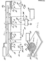
- Figure 1 is a diagrammatic view of the essential features of an embodiment of an apparatus in accordance with the present invention; and
- Figure 2 is a perspective view showing the configuration of the coils when in use.
- As shown in the Figures, apparatus 10 comprises a series of coaxial, identically constructed and dimensioned
flat coils 12, 12'. Each of thesecoils 12, 12' consists of a series of turns (not separately numbered) of an electricallynon-conductive tube 14 such as an extruded polyvinyl polymer tube located in two flat, parallel planes and aconductor 16 going through the interior of eachtube 14. Theseconductors 16 are typically multi-stranded wires which are sufficiently small in diameter to permit a cooling liquid such as, for example, a dielectric oil or distilled water to be circulated through thetubes 14 around theconductors 16. - Appropriate
conventional fittings 18 are provided at the ends (not separately numbered) of thetubes 14 for the purpose of joining the ends of thetubes 14 to manifolds or distributingpipes 20 used in connection with acoolant storage reservoir 22 and apump 24. Thesefittings 18 are formed in a conventional or known manner so that theconductors 16 extend through them so that theseconductors 16 may be connected as hereinafter indicated. - In the present invention, each
conductor 16 constitutes the electrically "active" part of acoil 12, 12' and is connected into atank circuit 26 across twoseparate capacitors 28 of equal capacitance value located in series with one another. All of thecoils 12, 12' and the associatedcapacitors 28 together constitute a tank circuit having a specific resonant frequency. - A known adjustable power supply 3n capable of being adjusted so as to operate at various frequencies is used to supply current at the noted resonant frequency to a
transformer 32 which in turn is connected to only one of thetank circuits 26. In the particular embodiment illustrated in Figure 1, thetransformer 32 is connected across only one of the twocapacitors 28 in the tank circuit 26. However, if desired, thistransformer 32 can be connected across both of thecapacitors 28 in thisparticular circuit 26. - All of the
circuits 26 are grounded byconventional grounds 34. In the interests of safety it is preferred to ground eachcircuit 26 between the capacitors 28 in eachcircuit 26 as shown. With the present invention . theparticular coil 12 which is driven by thepower supply 30 and thetransformer 32 may be any one of the individual coils used in the complete apparatus 10. - As shown in Figure 2, the
coils 12, 12' are assembled closely together in a stack of aligned, identical pancake-type coils and are preferably secured together as a unit by the use of a conventional, appropriate adhesive (not shown). Because they are used in this manner, in effect, thecoils 12 constitute a series of closely coupled transformer coils. As a consequence of this, the use of thepower supply 30 with a single coil 12 has the effect of driving the remainder of the coils 12' and, of course, the associatedtank circuits 26. - In order to achieve the degree of hysteresis required to heat the comparatively small area or region of the body where the hysteresis composition is located, it is necessary to drive the
particular circuit 26 connected to thepower supply 30 using a comparatively large amount of power. The exact amount of power required will, of course, depend on many factors. At the present time, it is considered<that the exact amount of power required to treat various different reasonably related treatments of neoplastic tissue should be judged on an empirical basis taking into consideration the factors which are discussed below. - The frequency of the AC current supplied to the
coil 12 and itsassociated circuit 26 is normally determined on the basis of the factors indicated in the preceding discussion relative to the background of the invention with a view to minimizing eddy current type heating losses while concurrently maximizing the efficiency of the hysteresis heating obtained. It is considered that a frequency of from 1000 to 5000 Hz, preferably about 2000 Hz, initially represents the most desirable balance between the competitive factors which are involved in achieving the desired hyperthermia using the apparatus of the invention and that theindividual tank circuits 26 should be formed to resonate at a specific frequency and that thepower supply 30 should be operated at this frequency. - As power is supplied to a
circuit 26 and its associatedcoil 12, a cooling liquid is supplied to theindividual coils 12 in an effort to prevent any temperature rise which would damage these coils or their manner of operation. However, in spite of this measure, some heating will normally occur in theindividual conductors 16 in thevarious coils 12, 12' and in connection with the various associatedcapacitors 28. Because of such heating, theindividual circuits 26 will change slightly as they are used and this in turn will affect the resonant frequency of the complete apparatus. - Because of this, as the complete apparatus 10 is operated, the frequency of the
power supply 30 used to drive directly onecircuit 26 and its associatedcoil 12 and the remainder of thecircuits 26 and coils 12' indirectly should be adjusted so as to always match the new resonant frequency of the complete collection ofcircuits 26. In order to further minimize power losses, it is considered highly preferable to utilize as theconductors 16 either wires composed of a twisted plurality of strands of individual wires or conventional Litz wires. - The utilization of such conductors may also be advantageous for another reason. As indicated, during the use of the
coils 12, 12' at high power levels, a cooling fluid must be circulated through thetubes 16, in order to prevent damage to either thetubes 14 or melting of theconductors 16. The surface configuration of either a twisted or a Litz wire conductor has been found to be effective in permitting efficient heat transfer from the conductor to the cooling liquid employed. - When using the apparatus 10, power is supplied from the
power supply 30 to aconnected tank circuit 26 at a frequency matching the resonant frequency of all of thecircuits 26 as a unit. When thisspecific circuit 26 is driven or powered in this manner, it sets up a flux field which couples with theadjacent coils 12 so that these adjacent coils are also powered in a transformer-like manner by mutual induction. In effect, onespecific coil 12 is used to drive all of the various coils 12' solely by mutual induction between the coils. This method has several significant advantages. Firstly, only comparatively low voltages are required at the terminals of the individual coils since they are electrically in parallel; a series-wound coil of the same total number of turns would require many kilovolts of excitation voltage, with accompanying high-voltage insulation requirements, corona discharge problems, and safety hazards. Secondly, thecircuits 26 are electrically isolated so that they do not all require exactly the same voltage, a requirement which would be necessary if all of thecircuits 26 were connected to a common voltage source. - It is not to be assumed from the above discussion that the apparatus 10 requires the use of
coils 12, 12' which are symmetrical relative to an axis. To increase the efficiency of the apparatus 10, it is desirable to construct all of thecoils 12, 12' so that they are of an identical oval shape such that their interiors reasonably conform to the non-rectilinear shape of a human body. When the interiors of the coils are of such a configuration, a relatively large segment of the body can be located within them. This optional feature of the apparatus is important in the treatment of many internal neoplasms located within the trunk of the body. Even the introduction of the heart within an alternating magnetic field having a frequency as used in the present apparatus does not apparently affect the body to any significant or material extent. Thus the apparatus of the invention can be used to treat a neoplasm which is immediately adjacent to or is associated with the heart in one manner or another. - The amount of time that a part of the body is generally within the coils when using the present invention varies, of course, depending upon the total amount of heat or the maximum temperature required in order to cause necrosis of the neoplastic growth. When the magnetic particles employed in the hysteresis composition have a Curie point in the range 420C to 90°C, excessive overheating is normally prevented by the loss of magnetic properties of the particles used as they reach a temperature corresponding to their Curie points, When, however, magnetic particles are used which have Curie points above the specific temperature range noted, it is considered highly desirable to carefully monitor the time that a specific area containing magnetic particles is generally within the coils and the power supplied to these coils. Generally speaking, at a specific power level the coils should not be operated any longer than is necessary to cause necrosis of neoplastic tissue. Since this is dependent upon both temperature and time, it is desirable to carefully monitor the temperature in the area of treatment.
- When using the apparatus, normal cells or tissue adjacent to the hysteresis composition will become heated to at least a degree and as a result such normal tissue or growth will frequently be necrosed. Normally, this does not present any significant problems. As is well known, the body has what may be regarded as inherent mechanisms for dealing with many different eventualities and is reasonably capable of disposing of both necrosed normal and neoplastic tissue or cells through normal metabolic processes. Further, the body is reasonably capable of developing what may be loosely referred to as scar tissue to compensate for normal growth which has been lost as a resalt of hyperthermia. Not infrequently, the body, through its own internal mechanisms, will develop barriers of a known or conventional type isolating areas where magnetic particles have been used from the normal metabolic operation of the body.
Claims (7)
Applications Claiming Priority (2)
| Application Number | Priority Date | Filing Date | Title |
|---|---|---|---|
| US06/223,727 US4392040A (en) | 1981-01-09 | 1981-01-09 | Induction heating apparatus for use in causing necrosis of neoplasm |
| US223727 | 1981-01-09 |
Related Parent Applications (2)
| Application Number | Title | Priority Date | Filing Date |
|---|---|---|---|
| EP82300125.0 Division | 1982-01-11 | ||
| EP82300125A Division EP0056697B1 (en) | 1981-01-09 | 1982-01-11 | Injectable compositions suitable for use in inductively heating neoplasms |
Publications (2)
| Publication Number | Publication Date |
|---|---|
| EP0208338A2 true EP0208338A2 (en) | 1987-01-14 |
| EP0208338A3 EP0208338A3 (en) | 1987-05-13 |
Family
ID=22837751
Family Applications (2)
| Application Number | Title | Priority Date | Filing Date |
|---|---|---|---|
| EP86111207A Withdrawn EP0208338A3 (en) | 1981-01-09 | 1982-01-11 | Induction heating apparatus |
| EP82300125A Expired EP0056697B1 (en) | 1981-01-09 | 1982-01-11 | Injectable compositions suitable for use in inductively heating neoplasms |
Family Applications After (1)
| Application Number | Title | Priority Date | Filing Date |
|---|---|---|---|
| EP82300125A Expired EP0056697B1 (en) | 1981-01-09 | 1982-01-11 | Injectable compositions suitable for use in inductively heating neoplasms |
Country Status (11)
| Country | Link |
|---|---|
| US (1) | US4392040A (en) |
| EP (2) | EP0208338A3 (en) |
| JP (1) | JPS57136463A (en) |
| AT (1) | ATE28128T1 (en) |
| AU (1) | AU557749B2 (en) |
| BR (1) | BR8205337A (en) |
| CA (1) | CA1203851A (en) |
| DE (1) | DE3276683D1 (en) |
| IL (1) | IL64735A0 (en) |
| MX (1) | MX151204A (en) |
| WO (1) | WO1982002339A1 (en) |
Cited By (1)
| Publication number | Priority date | Publication date | Assignee | Title |
|---|---|---|---|---|
| EP0474984A2 (en) * | 1990-09-10 | 1992-03-18 | Omron Corporation | Hyperthermia device |
Families Citing this family (58)
| Publication number | Priority date | Publication date | Assignee | Title |
|---|---|---|---|---|
| FR2532751A1 (en) * | 1982-09-07 | 1984-03-09 | Thomson Csf | Method and device for the remote measurement of the temperature at a point on living tissue, and a hyperthermal apparatus incorporating such a device |
| US4731239A (en) * | 1983-01-10 | 1988-03-15 | Gordon Robert T | Method for enhancing NMR imaging; and diagnostic use |
| US4610241A (en) * | 1984-07-03 | 1986-09-09 | Gordon Robert T | Atherosclerosis treatment method |
| US4776334A (en) * | 1985-03-22 | 1988-10-11 | Stanford University | Catheter for treatment of tumors |
| US4983159A (en) * | 1985-03-25 | 1991-01-08 | Rand Robert W | Inductive heating process for use in causing necrosis of neoplasms at selective frequencies |
| US4690130A (en) * | 1985-12-19 | 1987-09-01 | Mirell Stuart G | Electromagnetic therapy control system |
| CA1266094A (en) * | 1986-01-17 | 1990-02-20 | Patrick Earl Burke | Induction heating and melting systems having improved induction coils |
| JPH0626594B2 (en) * | 1986-03-27 | 1994-04-13 | グンゼ株式会社 | Embolic material used for selective hyperthermia |
| AU610497B2 (en) * | 1986-05-23 | 1991-05-23 | Trustees Of The University Of Pennsylvania, The | Portable electro-therapy system |
| US5052997A (en) * | 1987-04-10 | 1991-10-01 | The United States Of America As Represented By The Secretary Of The Department Of Health And Human Services | Diathermy coil |
| JPH0378537U (en) * | 1989-11-30 | 1991-08-08 | ||
| JP3398172B2 (en) * | 1993-04-09 | 2003-04-21 | 電気興業株式会社 | Heating temperature control method and high frequency induction heating temperature control device in high frequency induction heating |
| US5461215A (en) * | 1994-03-17 | 1995-10-24 | Massachusetts Institute Of Technology | Fluid cooled litz coil inductive heater and connector therefor |
| US5529568A (en) * | 1994-03-18 | 1996-06-25 | Surgery Futures Research, Inc. | Magnetic operating table |
| AT401348B (en) * | 1994-07-12 | 1996-08-26 | Kutschera Josef | Coil arrangement for generating a travelling electromagnetic field for therapeutic purposes |
| AUPP008197A0 (en) * | 1997-10-29 | 1997-11-20 | Paragon Medical Limited | Improved targeted hysteresis hyperthermia as a method for treating diseased tissue |
| US7074175B2 (en) | 2001-07-25 | 2006-07-11 | Erik Schroeder Handy | Thermotherapy via targeted delivery of nanoscale magnetic particles |
| US7731648B2 (en) * | 2001-07-25 | 2010-06-08 | Aduro Biotech | Magnetic nanoscale particle compositions, and therapeutic methods related thereto |
| US7951061B2 (en) * | 2001-07-25 | 2011-05-31 | Allan Foreman | Devices for targeted delivery of thermotherapy, and methods related thereto |
| US6997863B2 (en) * | 2001-07-25 | 2006-02-14 | Triton Biosystems, Inc. | Thermotherapy via targeted delivery of nanoscale magnetic particles |
| US6727483B2 (en) * | 2001-08-27 | 2004-04-27 | Illinois Tool Works Inc. | Method and apparatus for delivery of induction heating to a workpiece |
| US7015439B1 (en) | 2001-11-26 | 2006-03-21 | Illinois Tool Works Inc. | Method and system for control of on-site induction heating |
| US6713737B1 (en) * | 2001-11-26 | 2004-03-30 | Illinois Tool Works Inc. | System for reducing noise from a thermocouple in an induction heating system |
| US6956189B1 (en) | 2001-11-26 | 2005-10-18 | Illinois Tool Works Inc. | Alarm and indication system for an on-site induction heating system |
| US8038931B1 (en) | 2001-11-26 | 2011-10-18 | Illinois Tool Works Inc. | On-site induction heating apparatus |
| US6911089B2 (en) | 2002-11-01 | 2005-06-28 | Illinois Tool Works Inc. | System and method for coating a work piece |
| US20040084443A1 (en) * | 2002-11-01 | 2004-05-06 | Ulrich Mark A. | Method and apparatus for induction heating of a wound core |
| US20040156846A1 (en) * | 2003-02-06 | 2004-08-12 | Triton Biosystems, Inc. | Therapy via targeted delivery of nanoscale particles using L6 antibodies |
| ES2385933T3 (en) | 2003-02-20 | 2012-08-03 | University Of Connecticut Health Center | METHODS FOR THE PRODUCTION OF ALFA ANTIGEN MOLECULES COMPLEXES (2) MACROGLOBULIN. |
| US20050230379A1 (en) * | 2004-04-20 | 2005-10-20 | Vianney Martawibawa | System and method for heating a workpiece during a welding operation |
| US7627381B2 (en) | 2004-05-07 | 2009-12-01 | Therm Med, Llc | Systems and methods for combined RF-induced hyperthermia and radioimmunotherapy |
| US7510555B2 (en) | 2004-05-07 | 2009-03-31 | Therm Med, Llc | Enhanced systems and methods for RF-induced hyperthermia |
| US7422709B2 (en) * | 2004-05-21 | 2008-09-09 | Crosby Gernon | Electromagnetic rheological (EMR) fluid and method for using the EMR fluid |
| JP2008545665A (en) * | 2005-05-23 | 2008-12-18 | ユニベルシテ ドゥ ジュネーブ | Injectable superparamagnetic nanoparticles for hyperthermic treatment and use to form hyperthermic implants |
| US20130153440A9 (en) * | 2006-11-13 | 2013-06-20 | Kc Energy, Llc | Rf systems and methods for processing salt water |
| WO2011024159A2 (en) * | 2009-08-24 | 2011-03-03 | Refael Hof | Phase-change and shape-change materials |
| US8565892B2 (en) * | 2009-10-31 | 2013-10-22 | Qteris, Inc. | Nanoparticle-sized magnetic absorption enhancers having three-dimensional geometries adapted for improved diagnostics and hyperthermic treatment |
| US20110144546A1 (en) * | 2009-12-11 | 2011-06-16 | David Wayne Crothers | Heated simulated rock for massage therapeutic use |
| US20140228840A1 (en) * | 2011-09-28 | 2014-08-14 | Wake Forest University | Composite compositions and applications thereof |
| DE102012013534B3 (en) | 2012-07-05 | 2013-09-19 | Tobias Sokolowski | Apparatus for repetitive nerve stimulation for the degradation of adipose tissue by means of inductive magnetic fields |
| TWI584777B (en) * | 2014-08-22 | 2017-06-01 | 國立成功大學 | Flexible deep magnetic field generating apparatus |
| CN107206082B (en) | 2014-11-25 | 2022-01-11 | 纽菲斯有限公司 | Phase-change nanoparticles |
| US11491342B2 (en) | 2015-07-01 | 2022-11-08 | Btl Medical Solutions A.S. | Magnetic stimulation methods and devices for therapeutic treatments |
| US11266850B2 (en) | 2015-07-01 | 2022-03-08 | Btl Healthcare Technologies A.S. | High power time varying magnetic field therapy |
| US20180001107A1 (en) | 2016-07-01 | 2018-01-04 | Btl Holdings Limited | Aesthetic method of biological structure treatment by magnetic field |
| US10695575B1 (en) | 2016-05-10 | 2020-06-30 | Btl Medical Technologies S.R.O. | Aesthetic method of biological structure treatment by magnetic field |
| US10478634B2 (en) * | 2015-07-01 | 2019-11-19 | Btl Medical Technologies S.R.O. | Aesthetic method of biological structure treatment by magnetic field |
| US11253717B2 (en) | 2015-10-29 | 2022-02-22 | Btl Healthcare Technologies A.S. | Aesthetic method of biological structure treatment by magnetic field |
| US11247039B2 (en) | 2016-05-03 | 2022-02-15 | Btl Healthcare Technologies A.S. | Device including RF source of energy and vacuum system |
| US11464993B2 (en) | 2016-05-03 | 2022-10-11 | Btl Healthcare Technologies A.S. | Device including RF source of energy and vacuum system |
| US11534619B2 (en) | 2016-05-10 | 2022-12-27 | Btl Medical Solutions A.S. | Aesthetic method of biological structure treatment by magnetic field |
| US10583287B2 (en) | 2016-05-23 | 2020-03-10 | Btl Medical Technologies S.R.O. | Systems and methods for tissue treatment |
| US10556122B1 (en) | 2016-07-01 | 2020-02-11 | Btl Medical Technologies S.R.O. | Aesthetic method of biological structure treatment by magnetic field |
| WO2020131889A1 (en) | 2018-12-18 | 2020-06-25 | Boston Scientific Scimed, Inc. | Devices and methods for inducing ablation in or around occluded implants |
| DE202020005828U1 (en) | 2019-04-11 | 2022-09-06 | BTL Medical Solutions as. | Devices for beauty treatment of biological structures using radio frequency and magnetic energy |
| JP2023515722A (en) | 2020-05-04 | 2023-04-13 | ビーティーエル ヘルスケア テクノロジーズ エー.エス. | Devices and methods for unattended care of patients |
| US11878167B2 (en) | 2020-05-04 | 2024-01-23 | Btl Healthcare Technologies A.S. | Device and method for unattended treatment of a patient |
| US11896816B2 (en) | 2021-11-03 | 2024-02-13 | Btl Healthcare Technologies A.S. | Device and method for unattended treatment of a patient |
Citations (12)
| Publication number | Priority date | Publication date | Assignee | Title |
|---|---|---|---|---|
| DE523823C (en) * | 1931-04-28 | Hirsch Kupfer Und Messingwerke | Coil for induction furnaces, consisting of a conductive and a heat dissipating part | |
| US1873808A (en) * | 1930-03-03 | 1932-08-23 | Edgar L Bailey | Means for heating a conductive body |
| FR750400A (en) * | 1932-05-06 | 1933-08-09 | Ugine Infra | Device for power factor compensation of induction furnaces |
| US1980875A (en) * | 1930-01-01 | 1934-11-13 | Ajax Electrothermic Corp | Electric induction furnace |
| FR1244347A (en) * | 1959-09-07 | 1960-10-28 | Acec | Induction heating method and device |
| US3478156A (en) * | 1966-12-21 | 1969-11-11 | Ajax Magnethermic Corp | Polyphase stirring of molten metal |
| US3543762A (en) * | 1968-02-15 | 1970-12-01 | Dynapower Systems Corp Of Cali | Automatic control of electrotherapeutic apparatus |
| US3638657A (en) * | 1969-07-30 | 1972-02-01 | Hal C Mettler | Short wave diathermy circuit |
| LU71825A1 (en) * | 1974-11-07 | 1975-06-24 | ||
| FR2291773A1 (en) * | 1974-11-20 | 1976-06-18 | Fragnet Jean | HF emitter for medical use - has maximum output safety device with cutout meter |
| US4066065A (en) * | 1974-07-04 | 1978-01-03 | Werner Kraus | Coil structure for electromagnetic therapy |
| US4230129A (en) * | 1975-07-11 | 1980-10-28 | Leveen Harry H | Radio frequency, electromagnetic radiation device having orbital mount |
Family Cites Families (12)
| Publication number | Priority date | Publication date | Assignee | Title |
|---|---|---|---|---|
| US1900842A (en) * | 1925-12-21 | 1933-03-07 | Ajax Electrothermic Corp | Heater for rods and tubes |
| US3279996A (en) * | 1962-08-28 | 1966-10-18 | Jr David M Long | Polysiloxane carrier for controlled release of drugs and other agents |
| US3474777A (en) * | 1966-02-10 | 1969-10-28 | Amp Inc | Method of administering therapeutic agents |
| DE1284528B (en) * | 1967-03-08 | 1968-12-05 | Foerster | Device for the elimination of biological tissue by inductively heated bodies with temperature stabilizing properties |
| BE791632A (en) * | 1971-11-20 | 1973-05-21 | Schering Ag | SILICONIC RUBBER-BASED SUPPORTS FOR MEDICINAL PRODUCTS |
| US4106488A (en) * | 1974-08-20 | 1978-08-15 | Robert Thomas Gordon | Cancer treatment method |
| US4303636A (en) * | 1974-08-20 | 1981-12-01 | Gordon Robert T | Cancer treatment |
| JPS5315410A (en) * | 1976-07-23 | 1978-02-13 | Bucalo Louis | Transplanting body |
| US4266532A (en) * | 1976-11-17 | 1981-05-12 | Electro-Biology, Inc. | Modification of the growth, repair and maintenance behavior of living tissues and cells by a specific and selective change in electrical environment |
| DE2656317C2 (en) * | 1976-12-11 | 1986-06-19 | Kernforschungsanlage Jülich GmbH, 5170 Jülich | Process for the preparation of a suspension of loaded erythrocytes |
| US4323056A (en) * | 1980-05-19 | 1982-04-06 | Corning Glass Works | Radio frequency induced hyperthermia for tumor therapy |
| US4317979A (en) * | 1980-05-30 | 1982-03-02 | Westinghouse Electric Corp. | High current high frequency current transformer |
-
1981
- 1981-01-09 US US06/223,727 patent/US4392040A/en not_active Expired - Lifetime
- 1981-12-30 AU AU79124/81A patent/AU557749B2/en not_active Ceased
-
1982
- 1982-01-06 CA CA000393669A patent/CA1203851A/en not_active Expired
- 1982-01-07 MX MX190891A patent/MX151204A/en unknown
- 1982-01-07 BR BR8205337A patent/BR8205337A/en unknown
- 1982-01-07 WO PCT/US1982/000019 patent/WO1982002339A1/en unknown
- 1982-01-08 IL IL64735A patent/IL64735A0/en unknown
- 1982-01-09 JP JP57002183A patent/JPS57136463A/en active Pending
- 1982-01-11 DE DE8282300125T patent/DE3276683D1/en not_active Expired
- 1982-01-11 EP EP86111207A patent/EP0208338A3/en not_active Withdrawn
- 1982-01-11 EP EP82300125A patent/EP0056697B1/en not_active Expired
- 1982-01-11 AT AT82300125T patent/ATE28128T1/en not_active IP Right Cessation
Patent Citations (12)
| Publication number | Priority date | Publication date | Assignee | Title |
|---|---|---|---|---|
| DE523823C (en) * | 1931-04-28 | Hirsch Kupfer Und Messingwerke | Coil for induction furnaces, consisting of a conductive and a heat dissipating part | |
| US1980875A (en) * | 1930-01-01 | 1934-11-13 | Ajax Electrothermic Corp | Electric induction furnace |
| US1873808A (en) * | 1930-03-03 | 1932-08-23 | Edgar L Bailey | Means for heating a conductive body |
| FR750400A (en) * | 1932-05-06 | 1933-08-09 | Ugine Infra | Device for power factor compensation of induction furnaces |
| FR1244347A (en) * | 1959-09-07 | 1960-10-28 | Acec | Induction heating method and device |
| US3478156A (en) * | 1966-12-21 | 1969-11-11 | Ajax Magnethermic Corp | Polyphase stirring of molten metal |
| US3543762A (en) * | 1968-02-15 | 1970-12-01 | Dynapower Systems Corp Of Cali | Automatic control of electrotherapeutic apparatus |
| US3638657A (en) * | 1969-07-30 | 1972-02-01 | Hal C Mettler | Short wave diathermy circuit |
| US4066065A (en) * | 1974-07-04 | 1978-01-03 | Werner Kraus | Coil structure for electromagnetic therapy |
| LU71825A1 (en) * | 1974-11-07 | 1975-06-24 | ||
| FR2291773A1 (en) * | 1974-11-20 | 1976-06-18 | Fragnet Jean | HF emitter for medical use - has maximum output safety device with cutout meter |
| US4230129A (en) * | 1975-07-11 | 1980-10-28 | Leveen Harry H | Radio frequency, electromagnetic radiation device having orbital mount |
Cited By (3)
| Publication number | Priority date | Publication date | Assignee | Title |
|---|---|---|---|---|
| EP0474984A2 (en) * | 1990-09-10 | 1992-03-18 | Omron Corporation | Hyperthermia device |
| EP0474984A3 (en) * | 1990-09-10 | 1992-06-10 | Omron Corporation | Hyperthermia device |
| US5232433A (en) * | 1990-09-10 | 1993-08-03 | The Tokai University Juridical Foundation | Hyperthermia device |
Also Published As
| Publication number | Publication date |
|---|---|
| US4392040A (en) | 1983-07-05 |
| BR8205337A (en) | 1982-12-14 |
| CA1203851A (en) | 1986-04-29 |
| EP0056697B1 (en) | 1987-07-08 |
| ATE28128T1 (en) | 1987-07-15 |
| JPS57136463A (en) | 1982-08-23 |
| IL64735A0 (en) | 1982-03-31 |
| EP0208338A3 (en) | 1987-05-13 |
| EP0056697A2 (en) | 1982-07-28 |
| AU557749B2 (en) | 1987-01-08 |
| WO1982002339A1 (en) | 1982-07-22 |
| MX151204A (en) | 1984-10-09 |
| AU7912481A (en) | 1982-07-15 |
| DE3276683D1 (en) | 1987-08-13 |
| EP0056697A3 (en) | 1984-09-19 |
Similar Documents
| Publication | Publication Date | Title |
|---|---|---|
| EP0208338A2 (en) | Induction heating apparatus | |
| US4186729A (en) | Deep heating electrode | |
| US4305115A (en) | Electrostatic shield | |
| US4545368A (en) | Induction heating method for use in causing necrosis of neoplasm | |
| US4527550A (en) | Helical coil for diathermy apparatus | |
| US9586057B2 (en) | Magnetic stimulation methods and devices for therapeutic treatments | |
| US4679561A (en) | Implantable apparatus for localized heating of tissue | |
| US4237898A (en) | Apparatus for heating tissue and employing protection against transients | |
| US4028518A (en) | Device for superficially heating an adjacent body | |
| US9636519B2 (en) | Magnetic stimulation methods and devices for therapeutic treatments | |
| US2130758A (en) | Electrode for diathermy treatment and the like | |
| US4454883A (en) | Electrotherapeutic apparatus | |
| US4121592A (en) | Apparatus for heating tissue | |
| US5218185A (en) | Elimination of potentially harmful electrical and magnetic fields from electric blankets and other electrical appliances | |
| US5186181A (en) | Radio frequency thermotherapy | |
| US5000178A (en) | Shielded electromagnetic transducer | |
| US4402309A (en) | Therapeutic magnetic electrode | |
| Stauffer et al. | Practical induction heating coil designs for clinical hyperthermia with ferromagnetic implants | |
| EP0501048A1 (en) | Shielded electromagnetic transducer | |
| US3245408A (en) | Electrotherapy apparatus | |
| KR102234149B1 (en) | Ac magnetic field generator based on magnetic materials heating | |
| US5412182A (en) | Eddy current heating for hyperthermia cancer treatment | |
| US4325361A (en) | Deep heating electrode | |
| EP0058564A1 (en) | Improvements in or relating to electrotherapeutic apparatus | |
| US4823813A (en) | Electrostatic deep heating applicators |
Legal Events
| Date | Code | Title | Description |
|---|---|---|---|
| PUAI | Public reference made under article 153(3) epc to a published international application that has entered the european phase |
Free format text: ORIGINAL CODE: 0009012 |
|
| 17P | Request for examination filed |
Effective date: 19860827 |
|
| AC | Divisional application: reference to earlier application |
Ref document number: 56697 Country of ref document: EP |
|
| AK | Designated contracting states |
Kind code of ref document: A2 Designated state(s): AT BE CH DE FR GB IT LI LU NL SE |
|
| PUAL | Search report despatched |
Free format text: ORIGINAL CODE: 0009013 |
|
| AK | Designated contracting states |
Kind code of ref document: A3 Designated state(s): AT BE CH DE FR GB IT LI LU NL SE |
|
| 17Q | First examination report despatched |
Effective date: 19881013 |
|
| STAA | Information on the status of an ep patent application or granted ep patent |
Free format text: STATUS: THE APPLICATION IS DEEMED TO BE WITHDRAWN |
|
| 18D | Application deemed to be withdrawn |
Effective date: 19891110 |