EP0203820A2 - Multi-phase process for debossing and perforating a polymeric web to coincide with the image of one or more three-dimensional forming structures and apparatus for carrying out the method - Google Patents
Multi-phase process for debossing and perforating a polymeric web to coincide with the image of one or more three-dimensional forming structures and apparatus for carrying out the method Download PDFInfo
- Publication number
- EP0203820A2 EP0203820A2 EP86304110A EP86304110A EP0203820A2 EP 0203820 A2 EP0203820 A2 EP 0203820A2 EP 86304110 A EP86304110 A EP 86304110A EP 86304110 A EP86304110 A EP 86304110A EP 0203820 A2 EP0203820 A2 EP 0203820A2
- Authority
- EP
- European Patent Office
- Prior art keywords
- web
- forming structure
- film
- macroscopic
- apertures
- Prior art date
- Legal status (The legal status is an assumption and is not a legal conclusion. Google has not performed a legal analysis and makes no representation as to the accuracy of the status listed.)
- Granted
Links
Images


Classifications
-
- B—PERFORMING OPERATIONS; TRANSPORTING
- B29—WORKING OF PLASTICS; WORKING OF SUBSTANCES IN A PLASTIC STATE IN GENERAL
- B29C—SHAPING OR JOINING OF PLASTICS; SHAPING OF MATERIAL IN A PLASTIC STATE, NOT OTHERWISE PROVIDED FOR; AFTER-TREATMENT OF THE SHAPED PRODUCTS, e.g. REPAIRING
- B29C69/00—Combinations of shaping techniques not provided for in a single one of main groups B29C39/00 - B29C67/00, e.g. associations of moulding and joining techniques; Apparatus therefore
-
- A—HUMAN NECESSITIES
- A61—MEDICAL OR VETERINARY SCIENCE; HYGIENE
- A61F—FILTERS IMPLANTABLE INTO BLOOD VESSELS; PROSTHESES; DEVICES PROVIDING PATENCY TO, OR PREVENTING COLLAPSING OF, TUBULAR STRUCTURES OF THE BODY, e.g. STENTS; ORTHOPAEDIC, NURSING OR CONTRACEPTIVE DEVICES; FOMENTATION; TREATMENT OR PROTECTION OF EYES OR EARS; BANDAGES, DRESSINGS OR ABSORBENT PADS; FIRST-AID KITS
- A61F13/00—Bandages or dressings; Absorbent pads
- A61F13/15—Absorbent pads, e.g. sanitary towels, swabs or tampons for external or internal application to the body; Supporting or fastening means therefor; Tampon applicators
- A61F13/51—Absorbent pads, e.g. sanitary towels, swabs or tampons for external or internal application to the body; Supporting or fastening means therefor; Tampon applicators characterised by the outer layers
- A61F13/511—Topsheet, i.e. the permeable cover or layer facing the skin
- A61F13/512—Topsheet, i.e. the permeable cover or layer facing the skin characterised by its apertures, e.g. perforations
-
- A—HUMAN NECESSITIES
- A61—MEDICAL OR VETERINARY SCIENCE; HYGIENE
- A61F—FILTERS IMPLANTABLE INTO BLOOD VESSELS; PROSTHESES; DEVICES PROVIDING PATENCY TO, OR PREVENTING COLLAPSING OF, TUBULAR STRUCTURES OF THE BODY, e.g. STENTS; ORTHOPAEDIC, NURSING OR CONTRACEPTIVE DEVICES; FOMENTATION; TREATMENT OR PROTECTION OF EYES OR EARS; BANDAGES, DRESSINGS OR ABSORBENT PADS; FIRST-AID KITS
- A61F13/00—Bandages or dressings; Absorbent pads
- A61F13/15—Absorbent pads, e.g. sanitary towels, swabs or tampons for external or internal application to the body; Supporting or fastening means therefor; Tampon applicators
- A61F13/15577—Apparatus or processes for manufacturing
- A61F13/15707—Mechanical treatment, e.g. notching, twisting, compressing, shaping
- A61F13/15731—Treating webs, e.g. for giving them a fibrelike appearance, e.g. by embossing
-
- A—HUMAN NECESSITIES
- A61—MEDICAL OR VETERINARY SCIENCE; HYGIENE
- A61F—FILTERS IMPLANTABLE INTO BLOOD VESSELS; PROSTHESES; DEVICES PROVIDING PATENCY TO, OR PREVENTING COLLAPSING OF, TUBULAR STRUCTURES OF THE BODY, e.g. STENTS; ORTHOPAEDIC, NURSING OR CONTRACEPTIVE DEVICES; FOMENTATION; TREATMENT OR PROTECTION OF EYES OR EARS; BANDAGES, DRESSINGS OR ABSORBENT PADS; FIRST-AID KITS
- A61F13/00—Bandages or dressings; Absorbent pads
- A61F13/15—Absorbent pads, e.g. sanitary towels, swabs or tampons for external or internal application to the body; Supporting or fastening means therefor; Tampon applicators
- A61F13/51—Absorbent pads, e.g. sanitary towels, swabs or tampons for external or internal application to the body; Supporting or fastening means therefor; Tampon applicators characterised by the outer layers
- A61F13/511—Topsheet, i.e. the permeable cover or layer facing the skin
- A61F13/51104—Topsheet, i.e. the permeable cover or layer facing the skin the top sheet having a three-dimensional cross-section, e.g. corrugations, embossments, recesses or projections
-
- B—PERFORMING OPERATIONS; TRANSPORTING
- B26—HAND CUTTING TOOLS; CUTTING; SEVERING
- B26F—PERFORATING; PUNCHING; CUTTING-OUT; STAMPING-OUT; SEVERING BY MEANS OTHER THAN CUTTING
- B26F1/00—Perforating; Punching; Cutting-out; Stamping-out; Apparatus therefor
- B26F1/26—Perforating by non-mechanical means, e.g. by fluid jet
-
- B—PERFORMING OPERATIONS; TRANSPORTING
- B29—WORKING OF PLASTICS; WORKING OF SUBSTANCES IN A PLASTIC STATE IN GENERAL
- B29C—SHAPING OR JOINING OF PLASTICS; SHAPING OF MATERIAL IN A PLASTIC STATE, NOT OTHERWISE PROVIDED FOR; AFTER-TREATMENT OF THE SHAPED PRODUCTS, e.g. REPAIRING
- B29C51/00—Shaping by thermoforming, i.e. shaping sheets or sheet like preforms after heating, e.g. shaping sheets in matched moulds or by deep-drawing; Apparatus therefor
- B29C51/18—Thermoforming apparatus
- B29C51/20—Thermoforming apparatus having movable moulds or mould parts
- B29C51/22—Thermoforming apparatus having movable moulds or mould parts rotatable about an axis
- B29C51/225—Thermoforming apparatus having movable moulds or mould parts rotatable about an axis mounted on a vacuum drum
-
- B—PERFORMING OPERATIONS; TRANSPORTING
- B29—WORKING OF PLASTICS; WORKING OF SUBSTANCES IN A PLASTIC STATE IN GENERAL
- B29L—INDEXING SCHEME ASSOCIATED WITH SUBCLASS B29C, RELATING TO PARTICULAR ARTICLES
- B29L2031/00—Other particular articles
- B29L2031/48—Wearing apparel
- B29L2031/4871—Underwear
- B29L2031/4878—Diapers, napkins
Definitions
- the present invention has relation to a multi-phase process for debossing and perforating a substantially continuous web of substantially planar polymeric film so as to coincide with the image of one or more three-dimensional forming structures.
- the present invention has further relation to a multi-phase process for producing plastic webs which exhibit a combination of desirable attributes which were incompatible with one another when produced using single-phase forming processes of the prior art.
- the present invention has further relation to a multi-phase forming process capable of producing macroscopically expanded, three-dimensional, apertured polymeric webs comprised of materials which could not be effectively processed on single-phase forming processes of the prior art.
- the present invention has further relation to a multi-phase forming process which is capable of reliable, high-speed, continuous operation, thereby greatly reducing the cost of the unique plastic webs produced by said process.
- the present invention has still further relation to a multi-phase forming process for producing macroscopically expanded, three-dimensional, apertured plastic webs exhibiting highly desirable fluid and vapor transmission capabilities in addition to visual and tactile impressions which are actually preferred by consumers over woven and nonwoven fibrous webs when worn in contact with the skin.
- Macroscopically expanded, three-dimensional, apertured polymeric webs are generally Known in the art.
- the term "macroscopically expanded”, when used to describe three-dimensional plastic webs, ribbons and films, refers to webs, ribbons and films which have been caused to conform to the surface of a three-dimensional forming structure so that both surfaces thereof exhibit the three-dimensional pattern of said forming structure, said pattern being readily visible to the naked eye when the perpendicular distance between the viewer's eye and the plane of the web is 30cm .
- the term “planar”, when utilized herein to describe plastic webs, ribbons and films refers to the overall condition of the web, ribbon or film when viewed by the naked eye on a macroscopic scale.
- planar webs, ribbons and films may include webs, ribbons and films having fine-scale surface aberrations on one or both sides, said surface aberrations not being readily visible to the naked eye when the perpendicular distance between the viewer's eye and the plane of the web is about 30cm or greater.
- Thompson describes a macroscopically expanded, three dimensional topsheet comprised of liquid impermeable material, but provided with a pattern of tapered capillaries, said capillaries having a base opening in the plane of the topsheet and an apex opening remote from the plane of the topsheet, said apex opening being in intimate contact with the absorbent pad utilized in the disposable absorbent bandage.
- the Thompson topsheet allows the free transfer of fluids from the wearer's body into the absorbent element of the device while inhibiting the reverse flow of these fluids. This provides a relatively much drier surface in contact with the user than had previously been obtainable.
- FIG. 1 Another macroscopically expanded, three-dimensional, apertured plastic web well suited for use as a topsheet on absorbent bandages such as sanitary napkins is disclosed in commonly assigned U.S. Patent 4,342,314 issued to Radel and Thompson on August 3, 1982.
- the macroscopically expanded, three-dimensional plastic web disclosed in the Radel and Thompson patent exhibits a fiber-like appearance and tactile impression which has been favorably received by consumers when used as a wearer contacting surface.
- plastic webs of the aforementioned type can be made by applying a fluid pressure differential to the web while it is supported on a three-dimensional forming structure until the web is macroscopically expanded to comply with the three-dimensional cross-section of the forming structure on which it is supported.
- said fluid pressure differential is applied continuously until such time as aperturing of the web in areas coinciding with the apertures in the forming structure has been completed.
- the present invention pertains, in a particularly preferred embodiment, to a multi-phase method of making debossed and apertured polymeric webs which exhibit three-dimensional geometric forms, a number of which were at best difficult and at worst impossible to make using single-phase forming processes of the prior art.
- multi-phase processes of the present invention are capable of forming a film with very small and very large apertures or capillary networks immediately adjacent one another while accurately replicating the macroscopic, three-dimensional cross-section of the forming structure.
- it permits the formation of macroscopically expanded, three-dimensional, apertured plastic webs exhibiting a very large overall caliper in conjunction with very tiny apertures either in the land areas of the web or in the end walls of the capillary networks or both.
- Capillary networks having tiny apertures in their sidewalls may also be produced using embodiments of the present multi-phase process.
- webs exhibiting capillary networks having sidewalls extending in opposite directions from one another may also be produced.
- a web of molten polymeric resin is extruded directly onto a perforate, three-dimensional forming structure and subjected to a fluid pressure differential, typically vacuum.
- a fluid pressure differential typically vacuum.
- This phase of the operation provides good conformation of the web to the forming structure and imparts significant overall caliper to the web. Those portions of the web coinciding with a multiplicity of macroscopic cross-section apertures in the forming structure will also be apertured during this phase of the forming process.
- the molten web is thereafter cooled while still subject to the forming vacuum to prevent spring-back and consequent loss of caliper. At lower production speeds, e.g.
- a second forming phase preferably comprising a high pressure liquid jetting operation, which provides aperturing of the web not only in those areas coinciding with the very small apertures present in the forming structure, but also in any as yet unapertured areas of the web coinciding with any of the macroscopic cross-section apertures in the forming structure.
- the macroscopically expanded web can be fed to the high pressure liquid jetting operation while it is still subject to the forming vacuum used in the initial phase of the process. In this situation, the high pressure liquid jet not only provides aperturing of the web in those areas coinciding with the very small - apertures present in the forming structure, but may also afford some additional web cooling benefits.
- multi-phase web forming processes of the present invention comprise at least two discrete forming phases, each of which utilizes a fluid pressure differential to achieve its objective.
- One of the phases involves macroscopically conforming the polymeric web to the macroscopic cross-sectional profile of the forming structure on which it is supported while subject to one of the fluid pressure differentials. Substantial aperturing of the web in those areas coinciding with the macroscopic cross-section apertures in the forming structure usually occurs during this phase of the process.
- the other phase of the forming process also involves applying a fluid pressure differential to the plastic web. However, this phase is less concerned with macroscopically expanding the web to conform it to the three-dimensional cross-section of the forming structure. Rather, its primary objective is to fully aperture the web in all areas coinciding with apertures in the forming structure, including very fine apertures in the non-debossed land areas of the web and/or the end walls of the larger capillary networks formed therein.
- the discrete forming phases may be utilized on a single forming structure including all of the features desired in the resultant web or on multiple forming structures, each of which imparts only a portion of the desired features to the web.
- the fluid media applied during each of the forming phases of the present invention may be similar or dissimilar to one another, again depending upon the particular characteristics desired in the resultant polymeric web.
- the present invention will be described in the context of providing macroscopically expanded, three-dimensional, apertured plastic webs particularly suited for use as a wearer contacting surface on absorbent bandages such as disposable diapers, sanitary napkins, wound dressings and the like, the present invention is in no way limited to such applications. To the contrary, the present invention may be practiced to great advantage whenever it is desired to produce plastic films or webs exhibiting properties, characteristics, aesthetics, fineness of detail etc. not previously obtainable using prior art single-phase web forming processes.
- the patterns created may be of any desired shape, they may be regulated or random, reticulated or non-reticulated, continuous or interrupted, or any desired combination thereof.
- the detailed description of the structures disclosed herein and their suggested use as topsheets and/or backsheets in a disposable absorbent bandage context will allow one skilled in the art to readily adapt the invention to produce webs well suited to other applications.
- FIG. 1 A particularly preferred multi-phase, continuous forming process of the present invention is schematically illustrated in Figure 1.
- a web of substantially planar film 10 comprised of a polymeric material such as polyethylene is fed from a supply roll 1 onto the surface of a first forming drum 18 about which a forming structure 15 continuously rotates at substantially th'e same speed as the incoming web.
- the forming drum 18 preferably includes an internally located vacuum chamber 20 which is preferably stationary relative to the moving forming structure 15.
- a pair of stationary baffles 25, 30 approximately coinciding with the beginning and the end of the vacuum chamber 20 are located adjacent the exterior surface of the forming structure.
- the fluid pressure differential applicator means comprises a high pressure liquid nozzle 35 which discharges a jet of liquid 40, such as water, substantially uniformly across the entire width of the web 10. Details as to the construction, positioning and operating pressure of liquid nozzle 35 are fully set forth in the commonly assigned European Patent Application Publication No 0156471.
- Forming structure 15, a greatly enlarged fragmentary segment of which is illustrated in Figure 2, includes a multiplicity of relatively small apertures 16 across all or any desired portion of its surface.
- these apertures typically range in size between about 1 mil and about 10 mils in diameter. Their spacing may be in a regular pattern or it may vary randomly, as desired, in the resultant web.
- Methods of constructing suitable three-dimensional tubular forming members of this general type are disclosed in commonly assigned U.S. Patent 4,508,256 issued to Radel et al. on April 2, 1985 and commonly assigned U.S. Patent 4,509,908 issued to Mullane, Jr. on Aprii 9, 1985.
- the apertures 16 in the forming structure 15 may be of any desired shape or cross-ses tion when the forming structure is fabricated utilizing the laminar construction techniques generally disclosed in the aforementioned commonly assigned patents.
- tubular shaped forming structure 15 may be comprised of non-laminar construction and the desired pattern of apertures 16 created by means of laser drilling or the like. It is also possible to use belts or the like comprised of pliable material and operating continuously about a pair of rolls. In the latter circumstance it is generally desirable to provide suitable support beneath the pliable belt when it is subjected to the fluid pressure differential to avoid distortion.
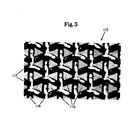
- Still another suitable forming structure which can be used to provide fine-scale aperturing of the polymeric web 10 comprises a woven wire mesh 115, such as that shown in the highly enlarged fragmentary photograph of Figure 3.
- a multiplicity of intersecting filaments 117 and 118 are interwoven with one another to provide a knuckle pattern, such as that generally shown in Figure 3, about the surface of the forming structure 115.
- the woven wire mesh filaments may be comprised of metal or polymeric material.
- the degree of conformance of the polymeric web 10 to the surface of the forming structure 15 and the size of the apertures created therein will be influenced by factors such as the temperature of the film 10 at the time it is subjected to the liquid jet 40, the pressure at which the jet 40 is applied to the surface of the film, the temperature of the liquid comprising the jet, the mass flux of the liquid jet, etc.
- the fluid pressure differential applied to the web when the fluid pressure differential applied to the web is in the form of vacuum, the higher the temperature of the incoming film 10, the greater will be the degree of conformance and aperturing.
- the fluid pressure differential applied to the web when the fluid pressure differential applied to the web is in the form of a high pressure liquid jet, as is the case in Figure 1, it is generally preferred that the incoming web be in a solid rather than a molten state.
- a web of molten resin 10 extruded from a conventional extruder 101 could be fed between a pair of chill rolls 3,4 prior to being fed onto the forming structure 15 to substantially cool the resin before it passes beneath liquid jet 40.
- the finely apertured polymeric web 10 is removed from the surface of the first fine-scale forming structure 15 about an idler roll 45 in the condition illustrated h;e greatly enlarged form in the inset of Figure 1C. Because of the presence of the cusps 13 surrounding each of the tiny apertures 11, the surface 17 which contacted forming structure 15 exhibits a much softer tactile impression than the surface 14 which was contacted by the liquid jet 40. Accordingly, surface 17 of the web is generally preferred as a wearer contacting surface over surface 14. The overall characteristics and benefits of such soft feeling polymeric webs are described in greater detail in the commonly assigned, co-pending U.S. Patent Application Serial No. 740125.
- the finely apertured web 10 may be fed to the second phase of the forming process for macroscopic expansion or to a rewind station for temporary storage. In the latter circumstance, application of the second phase of the process may be deferred until a later date, perhaps at a different location.
- the finely apertured web 10 may be utilized without further processing in an end product wherein fluid permeability and a soft tactile impression are particularly desirable, but a macroscopically expanded, three-dimensional cross-section is not essential.
- a web which is to undergo macroscopic, three-dimensional expansion is preferably fed onto a second forming structure 50 which operates about forming drum 58 so that its opposite surface 14 is placed in contact with forming structure 50.
- Forming drum 58 which is generally similar to forming drum 18 also includes a stationary vacuum chamber 55 located adjacent the interior of forming structure 50.
- Stationary baffles 70 and 80 substantially coincide with the leading and trailing edges of the vacuum chamber 55, thereby defining a second fluid pressure differential zone wherein a second liquid nozzle 90, generally similar to liquid nozzle 35, is positioned. Liquid nozzle 90 also discharges a relatively high pressure liquid jet 100 against the surface 17 of web 10 as it passes therebeneath.
- the pressure and mass flux rates of nozzle 90 are preferably adjusted independently of the pressure and mass flux rates used for nozzle 35. Additional details as to the construction, positioning and operating pressure of liquid nozzle 95 may be found in the commonly assigned, European Patent Application Publication No. 0156471.
- the macroscopic cross-section of forming structure 50 is visible in the greatly enlarged fragmentary perspective of Figure 4.
- the web of film 10 containing fine-scale apertures 11 is fed onto the exterior surface of forming structure 50 such that its surface 14 contacts the forming structure, while its surface 17 is oriented toward fluid nozzle 90. Accordingly, the small cusps 13 of the apertures 11 are oriented toward nozzle 90.
- the capillary networks 12 are also ruptured to form apertures 12b in the shape of the apertures 56 in the forming structure.
- the forming structure 50 exhibits a fiber-like cross-section of the type generally disclosed in commonly assigned U.S. Patent 4,342,314 issued to Radel et al. on August 3, 1982.
- the macroscopically expanded, three-dimensional, apertured web 10 exhibits a similar cross-section.
- the macroscopically expanded, three-dimensional, apertured polymeric web 10 is removed from forming structure 50 and wrapped about idler rolls 110 and 120 from whence it may be fed either to a rewinding station for temporary storage or directly to converting lines where it may be applied to making finished product structures, such as disposable absorbent bandages.
- the latter approach is particularly desirable, since it minimizes the loss of caliper which sometimes results when macroscopically expanded, three-dimensional, polymeric webs are rewound under tension.
- the fully processed plastic web of film 10 exhibits a macroscopic cross-section generally similar to that shown in the aforementioned commonly assigned U.S. Patent 4,342,314 to Radel et al.
- web 10 additionally exhibits a fine-scale pattern of apertures 11.
- each of the fine-scale apertures 11 actually forms a small capillary network resembling a tiny volcano, the outermost edges of which end in silky feeling cusps 13.
- films of the type generally illustrated in Figure 1 E are also capable of exhibiting excellent fluid handling and skin dryness benefits, i.e., large volumes of fluid deposited on surface 17 are rapidly transferred to surface 14 of the web by virtue of the relatively large cross-section of capillary networks 12, while capillary driven skin drying benefits are provided via the small scale apertures 11 present in the non-debossed land areas which normally contact the wearer's skin in use.
- the upward projections associated with the tiny apertures 11 act as a network of baffles during gush flow situations, i.e., the large quantities of liquid deposited on surface 17 are caused to flow in many different directions before reaching an edge of the absorbent structure, thereby increasing the probability that the liquid will enter one or more capillary networks 12 before reaching an edge of the absorbent structure. This, in turn, reduces leakage from the edges of the absorbent bandage.
- FIG. 5 is a simplified schematic illustration of an alternative multi-phase polymeric web forming process of the present invention. Like the process generally illustrated in Figure 1, the process shown in Figure 5 is carried out in two discrete phases. As can be seen from a comparison of Figures 5A and 5B to Figures 1B and 1C, respectively, the first phase of the process which provides the fine-scale apertures 11 in the web of film 10 is essentially identical. However, in the embodiment shown in Figure 5, the film is fed directly onto a second forming structure 50, identical to the one shown in Figure 1, without reverse wrapping of the film. Accordingly, surface 17 is placed in contact with forming structure 50, while surface 14 is placed so that it will be contacted by the liquid jet 100 issuing from fluid nozzle 90.
- the second phase of the process shown in Figure 5 is substantially identical with that shown in Figure 1.
- the cross-section which results after passage of the web of film under fluid nozzle 90 is generally shown as 10' in Figure 5C.
- the web of film 10' has been caused to assume the macroscopic, three-dimensional cross-section of forming structure 50 and has been apertured in those areas coinciding with apertures 56 in the forming structure.
- the capillary networks 12' thus formed are generally similar to the capillary networks 12 shown in web 10 of Figure 1 with the exception that the cusps 13 of the small apertures 11 are oriented toward rather than away from the forming structure 50.
- the macroscopically expanded, three-dimensional, apertured web of film 10' is passed about idler roll 110 and fed either to suitable rewind apparatus for temporary storage or directly to a converting operation for incorporation into the final product in which the web is to be employed.
- the final cross-section of the resultant web 10' is shown after removal from forming structure 50 in the greatly enlarged inset of Figure 5D. While the web of film 10' offers many of the same performance attributes relative to fluid handling as the web of film 10 shown in Figure 1E, it exhibits a different tactile response, particularly when one touches the non-debossed land areas of the web. This is because of the difference in orientation of the cusps 13 of the fine scale apertures 11 located substantially throughout the macroscopic cross-section of the web. Webs of the type disclosed in Figure 5D and their advantages are also discussed in detail in the aforementioned commonly assigned U.S. Patent Application Serial No. 740083.
- process embodiments of the present invention which utilize multiple forming structures offer considerable flexibility with respect to the types of characteristics which may be provided in a single, macroscopically expanded, three-dimensional, apertured plastic web.
- they permit the production of macroscopically expanded webs exhibiting a substantially uniform microscopic cross-section not only across the non-debossed land areas of the web's cross-sectional profile, but also along the sidewalls of the capillary networks formed in the web as it undergoes macroscopic expansion.
- multi-phase process embodiments illustrated in Figures 6, 8, 9 and 10 are illustrative of multi-phase forming processes of the present invention which are carried out utilizing only a single forming structure containing not only the desired macroscopic cross-sectional profile, but also the desired fine-scale aperturing pattern.
- FIG. 6 is a simplified schematic illustration of one such process of the present invention.
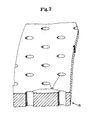
- the single three-dimensional forming structure 350 utilized on forming drum 318, which is generally similar to forming drums 18 and 58 of Figure 1, is shown in the greatly enlarged, fragmentary perspective view of Figure 7.
- the macroscopic cross-sectional profile of forming structure 350 is generally similar to that of forming structure 50 shown in Figure 4.
- Macroscopic cross-section apertures 356 correspond generally to macroscopic cross-section apertures 56 of the forming structure 50 shown in Figure 4.
- forming structure 350 also includes a multiplicity of much smaller apertures 316 extending from the film contacting to the non-film contacting surface of the forming structure. These apertures 316 are of the same general size range as the apertures 16 in forming structure 15 shown in Figure 2. If the forming structure 350 is made- utilizing the laminar construction techniques generally disclosed in commonly assigned U.S. Patent 4,508,256 issued to Radel and Thompson on April 2, 1985,
- these relatively small apertures 316 may be provided by etching each of the lamina utilized to make the composite forming structure 350 prior to final assembly.
- the apertures 316 are extremely small in size, it may be desirable to form a laminate forming structure 50 in the manner generally disclosed in the aforementioned commonly assigned U.S. Patent to Radel et al. and thereafter utilize laser drilling techniques to add the desired pattern of small apertures 316 to form the structure 350. This avoids filling of the small apertures 316 by the copper plating used to bond the various lamina to one another during the furnace brazing operation, as generally taught in the aforementioned patent to Radel et al.
- the multi-phase polymeric web forming process generally illustrated in Figure 6 is particularly desirable in those circumstances where it is desired to provide a relatively large overall caliper in the resultant plastic web, as well as good replication of the macroscopic, three-dimensional cross-section of the forming structure. Deep drawing of the film is generally best carried out while the film is at an elevated temperature and subject to a sustained fluid pressure differential such as vacuum. In the embodiment disclosed in Figure 6, this is preferably accomplished by mounting a conventional extruder 301, similar to extruder 101 in Figure 1, such that a continuous web of thermoplastic resin 310, similar to web of resin 10 in Figure 1A, is extruded at a temperature above the melt temperature directly onto the surface of forming structure 350.
- the web of relatively soft resin 310 passes beneath a first stationary baffle 325 and is immediately subjected to a fluid pressure differential via vacuum chamber 320 located in fixed position at the interior of forming drum 318.
- hot air jets may be mounted opposite vacuum chamber 320 to assist in causing the molten resin 310 to macroscopically conform to the cross-section of forming structure 350 and to rupture to form apertures substantially coinciding with the macroscopic cross-section apertures 356 in the forming structure 350.
- a second stationary baffle 330 and a cooling liquid nozzle 335 are preferably used to apply a low-pressure, e.g., typically below about 50 psig, spray of cooling liquid 340 to the deeply drawn web 310 prior to its leaving the influence of vacuum chamber 320.
- the baffle 330 helps to prevent the cooling liquid 340 from reaching the vacuum forming zone, as this could adversely impact upon the macroscopic web conforming and aperturing operation.
- the macroscopic cross-section of the web 310 is generally as shown in the greatly enlarged inset of Figure 6A.
- the web 310 has been macroscopically conformed to the three-dimensional cross-section of forming structure 350 and capillary networks 312 corresponding to macroscopic cross-section apertures 356 in the forming structure have been formed.
- the sidewalls of the capillary networks 312a correspond to the sidewalls of the macroscopic cross-section apertures 356 in the forming structure 350
- the apertures 312b in the end walls of the capillary networks 312 correspond substantially in cross-section to the cross-section of the apertures 356 in forming structure 350.
- the relatively small apertures 316 in forming structure 350 do not significantly impact upon the web 310 when the web is subjected to suction via vacuum chamber 320. This is due to the fact that once the web 310 has been apertured in those areas coinciding with macroscopic cross-section apertures 356, there is normally insufficient fluid pressure differential remaining on opposite sides of the web to cause conformance and aperturing of the web in those areas corresponding to the relatively fine-scale apertures 316 in forming structure 350.
- the fine scale apertures corresponding to apertures 316 in forming structure 350 are preferably produced intermediate a pair of stationary baffles 370, 380 by means of a high pressure liquid nozzle 390 which discharges a liquid jet 400 against the exposed surface 314 of the web, as generally shown in Figure 6.
- the high pressure liquid jet 400 which is substantially the same as the high pressure liquid jet 40 employed in the process embodiment shown in Figure 1, causes the macroscopically expanded web 310 to conform and rupture in those areas corresponding to apertures 316 in the forming structure 350.
- a secondary fixed position vacuum chamber 355 located generally opposite the liquid nozzle 390 captures the liquid 400 which passes through both capillary networks 312 and fine scale apertures 311 in the plastic web 310 and recycles it to one or more pumps (not shown) prior to its return to the nozzle from which it issued.
- This high pressure liquid jetting operation not only completes the processing operation by providing fine scale aperturing of the web in its non-debossed land areas, but reinforces conformance of the web to the macroscopic cross-section of the forming structure and completely apertures any of the unapertured portions of the web corresponding to apertures 356 in the forming structure.
- the cross-section of the finished web is shown in the greatly enlarged inset of Figure 6C.
- the web 310 is somewhat similar to the web 10' shown in Figure 5D. However, there is one principal difference, namely, the sidewalls 312a of capillary networks 312 are substantially unapertured.
- the completed web passes about idler roll 410 from whence it may be forwarded either to suitable rewinding apparatus for temporary storage or directly to converting operations for incorporation into products employing the plastic web thus produced.
- FIG 8 there is shown still another embodiment of the present multi-phase web processing invention wherein a single forming structure is utilized to provide macroscopic expansion/macroscopic aperturing of a plastic web as well as fine scale aperturing of the non-debossed land areas of the web.
- a forming structure 350 identical to that employed in the process of Figure 6 operates about forming drum 518, which is generally similar to forming drum 318.
- a pair of stationary vacuum chambers 520 and 555 are located adjacent one another at the interior of the forming drum.
- a web of plastic 310 is fed in a substantially planar condition from a supply roll 501 onto the surface of forming structure 350.
- a liquid jet nozzle 535 which discharges a high pressure liquid jet 540 against the exposed surface of the web 310.
- the high pressure liquid jet 540 causes macroscopic conformance of the web, thereafter designated as 310' to avoid confusion with the web processed in accordance with the process shown in Figure 6, as well as aperturing of those portions of the web coinciding with the macroscopic cross-section apertures 356 in forming structure 350.
- the web 310' exhibits a multiplicity of capillary networks 312', each having interconnected, non-apertured side walls 312a' ending to form apertures 312b' corresponding to macroscopic cross-section apertures 356 in forming structure 350.
- the web cross-section 310' shown in Figure 8A is generally similar in shape to the web cross-section 310 shown in Figure 6A.
- the overall length of capillary networks 312' is generally not as great as when vacuum forming is utilized, nor is the image of the forming structure 350 quite as sharp as when the high temperature vacuum forming approach generally illustrated in Figure 6 is employed.
- the high pressure liquid jet nozzle such as nozzle 90 in Figure 1, nozzle 540 in Figure 8 and nozzle 2090 in Figure 17 is typically operated at a pressure in the range of 2757 kPa to 5515 kPa and a water flow rate in the range of 11.9 liters per minute to 20.86 liters per minute per cross-machine direction cm of width of the plastic web.
- the high pressure liquid jet nozzle such as nozzle 35 in Figure 1, nozzle 390 in Figure 6, nozzle 590 in Figure 8, nozzle 790 in Figures 9 and 10, and nozzle 2035 in Figure 17, is typically operated at a pressure in the range of 55 15 kPa to _8272 kPa and water flow rates on the order of 1 1 .9 liters to 20.86 liters per minute per cross-machine direction cm of web width.
- the effect of the high pressure liquid jet 600 upon the macroscopically expanded web 310' is substantially identical to that of high pressure liquid jet 400 shown in Figure 6, i.e., fine scale apertures 311' are created in those areas coinciding with fine scale apertures 316 in forming structure 350.
- Small cusps 313' are formed on surface 317' of the web about the periphery of each of the fine scale apertures 311'.
- the resultant web 310' shown in Figure 8B is identical to web 310 shown in Figure 6B.
- water passing through the web from the liquid nozzles is collected in vacuum chambers 520 and 555 and is preferably recycled to one or more pumps which return the liquid to the nozzles from which it issued.
- the resultant web 310' is removed from forming structure 350 about idler roll 610 in the condition generally illustrated in Figure 8C and is thereafter rewound or fed directly to subsequent converting operations.
- drying macroscopically expanded, three-dimensional, apertured polymeric webs of the present invention to remove moisture left on its surface by the water assisted cooling and/or jetting operations described herein may be desirable, particularly in the event it is intended to rewind the web for temporary storage prior to undertaking converting operations.
- This may be accomplished by many and varied web drying techniques well known in the art, e.g., blow drying with hot air, wrapping the web about a multiplicity of rolls which apply centrifugal forces to sling the water from the web, etc.
- a particularly preferred drying approach which subjects the moving web to ultrasonic vibration is disclosed in the aforementioned commonly assigned, European Application Publication No. 0156471.
- Figure 9 discloses still another embodiment of the present invention which utilizes only a single three-dimensional forming structure.
- the process shown in Figure 9 employs a forming structure 350 generally similar to that shown in Figures 6 and 8.
- the forming structure 350 rotates about forming drum 718, generally similar to forming drum 318.
- Forming drum 718 includes a single, internally located; stationary vacuum chamber 720.
- the forming structure 350 is preferably fed by means of an extruder 701 which supplies a web of molten resin 310 directly onto its surface.
- a first stationary baffle 725 is aligned substantially even with the leading edge of vacuum chamber 720.
- the relatively high temperature of the web of soft resin 310 aids the web in conforming to the macroscopic cross-section of forming structure 350 under the influence of suction from vacuum chamber 720 in a manner substantially identical to that disclosed in connection with the first phase of the process disclosed in Figure 6.
- the cross-section of web 310 upon aperturing of those portions of the web coinciding with apertures 356 in the forming structure is generally as shown in Figure 9A, which is substantially identical to that of the web 310 shown in Figure 6B.
- the web embodiment 310 shown in Figure 9 is preferably cooled while still subject to the forming vacuum provided in chamber 720. Since it is generally desirable to reduce the temperature of the macroscopically expanded web to its solid state temperature prior to subjecting it to high pressure liquid jetting to avoid damage, a low pressure liquid spray 740 is preferably applied to the web adjacent stationary baffle 730 by means of a low pressure liquid nozzle 735. As pointed out earlier herein, the need for such liquid-assisted cooling generally increases as the web production speed increases beyond about 50 feet per minute.
- Fine scale aperturing and further cooling of the web are provided via high pressure liquid nozzle 790 located intermediate stationary baffles 730 and 780.
- the high pressure liquid jet nozzle 790 discharges a liquid jet 800 onto the exposed surface of the macroscopically conformed web 310.
- the liquid jet 800 creates apertures 311 corresponding to the small apertures 316 in the forming structure, as generally illustrated in Figure 9B, which is substantially identical to the cross-section shown in Figure 6B.
- the temperature of the liquid jet 800 is sufficiently low that it aids in further cooling the web 310, thereby better preserving the macroscopic cross-section imparted to the film by the suction emanating from within vacuum chamber 720.
- Figure 9 functions in a manner generally similar to that of Figure 6 utilizing a slightly different apparatus configuration, the chief difference involving the use of a single vacuum chamber 720 spanning both forming phases.
- the resultant web 310 shown in greatly enlarged cross-section in the inset of Figure 9C is substantially identical to the web shown in Figure 6C.
- the web 310 is fed about an idler roll 795 and thereafter directed either to suitable rewind apparatus or to a converting operation.
- the process embodiment shown in Figure 10 is substantially identical to the process embodiment shown in Figure 9 with one major exception, the configuration of the forming structure.
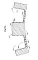
- the forming structure 850 utilized in the embodiment of Figure 10 is shown in greatly enlarged fragmentary perspective in Figure 11.
- the forming structure 850 exhibits an overall cross-sectional pattern similar to that of forming structure 50 shown in Figure 4, including a multiplicity of macroscopic cross-section apertures 856 which are generally similar to apertures 56 in forming structure 50.
- the base of the apertures 856 is closed by means of a perforate wall 857.
- This perforate wall 857 includes a multiplicity of relatively small apertures 816, as generally shown in Figure 11.
- a web of soft heated resin 810 is preferably extruded from extruder 701 onto the surface of forming structure 850, as generally shown in Figure 10.
- the influence of suction emanating from within vacuum chamber 720 causes the web 810 to assume the macroscopic profile of the forming structure 850, as generally shown in Figure 10A.
- the fluid pressure differential applied by the vacuum chamber 720 is generally not sufficient to cause rupture of the web in those areas coinciding with apertures 816 in the forming structure.
- a low pressure liquid spray 740 may be applied adjacent stationary baffle 730 by means of a low pressure liquid nozzle 735. Since the web is not apertured at this point, the applied cooling liquid cannot pass directly through the web at the point of application. Accordingly, alternative liquid collection means may be provided adjacent the lateral edges of the web. Preferably cooling nozzle 735 is so repositioned adjacent the periphery of forming drum 718 that the bulk of the applied cooling liquid will drain toward high pressure liquid nozzle 790 by gravity.
- high pressure liquid nozzle 790 issues a jet of liquid 800 against the exposed surface 814 of the macroscopically expanded web 810.
- the high pressure liquid jet 800 apertures the web 810 in those areas which are as yet unapertured, in this case those areas coinciding with apertures 816 in the forming structure.
- the liquid jet 800 preferably further assists in further cooling the web 810 in its fully conformed and maximally distended condition, since it is at this point still subject to the forming vacuum.
- each capillary network 812 is formed by substantially continuous, interconnected, imperforate sidewalls 812a.
- Each capillary network 812 also includes an end wall portion 812b which contains a multiplicity of relatively small apertures 811 corresponding to apertures 816 in forming structure 850.
- the apertures 811 form small capillary networks, each resembling a volcano having small cusps 813 about its periphery on surface 817 of the web.
- Macroscopically expanded, three-dimensional, apertured polymeric webs of the type generally disclosed in Figure 10C are believed particularly well suited for use in those situations where it is desired to isolate the wearer's skin from a moist absorbent member adjacent the lowermost surface 817 of the web, yet provide vapor permeability through the small apertures 811 provided in the end walls 857 of the capillary networks 812. Details of and advantages afforded by webs of the aforementioned type are more fully described in the commonly assigned U.S. Patent Application Serial No. 740083.
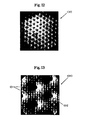
- Figure 12 is a plan view photograph, enlarged many times actual size, of a macroscopically expanded, three-dimensional, apertured plastic web made via a process of the type generally disclosed in Figure 1, but exhibiting a different macroscopic, three-dimensional pattern.
- the web 1010 shown in Figure 12 was formed from 1 mil thick polyethylene which was first apertured on a fine scale mesh screen comprised of wire monofilaments having a diameter of 0.094mm and a mesh count of 47 filaments by 47 filaments per square cm.
- the finely apertured web was thereafter reverse wrapped onto a macroscopic forming structure of the type generally similar to that disclosed in Figure 4, but exhibiting a different macroscopic, three-dimensional pattern.
- the macroscopic forming structure exhibited an overall thickness of 0.41mm. and a regularly spaced pattern of substantially round apertures, each measuring approximately 0.66mm at its point of maximum width, said apertures being spaced approximately 1.70mm from one another, center-to-center distance.
- the web was formed using a two-phase forming process of the type generally disclosed in Figure 1 by applying a pressure of 6894 k P a and a water flow rate of 14.9 Iiters per minute per cm of web width at high pressure liquid nozzle 35 and a pressure of 3447 kP a and a water flow rate of 11.9 litersper minute per cm of web width at high pressure liquid nozzle 90.
- the vacuum at chamber 20 was maintained at 6.75 kP a, and the vacuum at chamber 55 was maintained at 6.75 kPa .
- the resultant web 1010 exhibited an overall caliper of approximately 0.51mm, as measured under no load, and a soft and pleasing tactile impression, particularly in those non-debossed areas coinciding with the land areas of the forming structure.
- Figure 13 is a further enlarged photograph of a section of the web shown generally in Figure 12.
- the tiny apertures 1011 the cusps of which are oriented out of the plane of the paper correspond to the void spaces at the interstices formed between the intersecting filaments of the first woven wire forming structure, while the macroscopic cross-section capillary networks 1012, which are oriented into the plane of the paper, correspond to the macroscopic cross-section apertures present in the macroscopic forming structure.
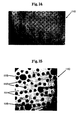
- Figure 14 is a plan view photograph, enlarged many times actual size, of an alternative plastic web made utilizing a multi-phase web forming process generally similar to that disclosed in Figure 6.
- This particular web 1110 exhibits fine-scale apertures in combination with macroscopic cross-section capillary networks of several different sizes.
- the relatively small apertures 1111 which form iny volcano-shaped capillary networks correspond to the fine-scale apertures which are present in the land areas of the macroscopic forming structure on which the web was formed, while the macroscopic cross-section capillary networks 1112 and 1115 correspond to the macroscopic cross-section apertures which are also present in the forming structure.
- the cusps associated with fine-scale apertures 1111 and the capillary networks 1112 and 1115 are all oriented into the plane of the paper.
- Figure 16 is a plan view photograph of a polymeric web of the type generally disclosed in Figure 10, enlarged many times actual size.
- the web 1210 was processed generally in accordance with the multi-phase process schematically shown in Figure 10. It includes a multiplicity of capillary networks 1212 corresponding to the capillary networks present in the forming structure.
- the apertures 1211 located in the end walls of the capillary networks correspond to small apertures located. in the end walls of the capillary networks contained in the forming structure.
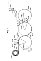
- FIG 17 is yet another simplified schematic illustration of a multi-phase polymeric web forming process of the present invention. Like the process generally illustrated in Figure 1, the process shown in Figure 17 is carried out in two discrete phases.
- Film supply roll 2001 is substantially equivalent to film supply roll 1 in Figure 1;
- web 2010 is substantially equivalent to web 10 in Figure 1;
- forming drums 2018 and 2058 are substantially equivalent to forming drums 18 and 58, respectively;
- vacuum chambers 2020 and 2055 are substantially equivalent to vacuum chambers 20 and 55 in Figure 1;
- stationary baffles 2025 and 2030 are substantially equivalent to stationary baffles 25 and 30 in Figure 1;
- forming structures 2015 and 2010 are substantially equivalent to forming structures 15 and 50 in Figure 1;
- first phase high-pressure nozzle 2035 which applies a high pressure liquid jet 2040 is substantially equivalent to high pressure liquid nozzle 35 which applies a high pressure liquid jet 40 in Figure 1.
- the process system illustrated in Figure 17 employs a nip type transfer between forming structure 2015 and forming structure 2050. This permits transfer of the web 2010 without loss of register between the patterns on forming structures 2015 and 2050. This is possible because the nip transfer avoids machine direction stretching of the web until both phases of the process have been carried out.
- the process system illustrated in Figure 17 differs from that illustrated in Figure 1 in one principal aspect.
- the second phase high pressure liquid nozzle 2090 which is substantially equivalent to high pressure liquid nozzle 90 in Figure 1
- a pair of stationary baffles 2070 and 2080 enclose high pressure nozzle 2090.
- the latter baffles are located within the drum 2068.
- High pressure liquid nozzle 2090 discharges a high pressure liquid jet 2100 substantially equivalent to high pressure liquid jet 100 in Figure 1.
- mask element 2065 permits the high pressure liquid jet 2100 to contact web 2010 only in those areas coinciding with the openings in the apertured mask element 2065.
- the openings in the mask element 2065 can be of any desired shape and may, for example, include a logo or similar decorative pattern which will define the pattern of macroscopic expansion which will be carried out as liquid jet 2100 contacts web 2010 while it is supported on forming structure 2050.
- An exemplary mask pattern is illustrated in Figure 18, which is taken along view line 18-18 of Figure 17. This particular pattern comprises a multiplicity of apertures 2088, each resembling an infant with outstretched arms and legs.
- the cross-section of web 2010 after high pressure water jetting by first phase nozzle 2035, if examined at the inset labeled "A" in Figure 17, will be identical to that of web 10 shown in Figure 1B.
- the cross-section of that portion of the web 2010 which coincides with the apertures 2088 in mask element 2065, if examined at the inset labeled "B" in- Figure 17, will be substantially identical to that of web 10 in Figure 1 E.
- the finally processed web embodiment 2010 is preferably removed from forming structure 2050 about a series of idler rolls 2110, 2120 and 2130, from whence it is directed either to suitable rewind apparatus or to on-line converting operations, as desired.
- Processing systems of the type generally shown in Figure 17 are particularly preferred in those situations where it is desirable to hold close register between the pattern on forming structure 2015 and the pattern on forming structure 2050.
- a mask element such as 2065, permits the producer to utilize a wider range of liquid jetting pressures to issue from high pressure liquid nozzle 2090 since there is no degradation of any characteristics initially imparted to those portions of the web which do not coincide with apertures 2088 in mask element 2065 as it passes beneath nozzle 2090.
- the macroscopically expanded, three-dimensional apertured web 1010 shown in Figures 12 and 13 was made in step-wise fashion, generally following the two stages of the process disclosed in Figure 1.
- the input web (10) was polyethylene, 0.025mm. thick (Consolidated Thermoplastics, #24765, Harrington, Delaware 19952).
- This web (10) was fed onto forming structure (15) at a speed of 152.5m per minute and subjected to the high pressure water jet (40).
- the water temperature was 74°C, the water pressure about 6894 k Pa, and the water flow about 14.9 liters per minute per cross-machine direction cm of web width.
- the forming structure was a woven wire screen of 47 x 47 mesh/cm, having 0.094mm wires.
- This first stage produced a web containing a multiplicity of small apertures, approximately 0.10mm in diameter, at a density of 4 7 such apertures per linear cm in both directions. This finely apertured web was then wound onto a take-up roll.
- the second stage was carried out by taping a 15cm by 30cm portion of the aforementioned finely apertured web onto a different forming structure. This forming structure contained apertures of approximately 0.66mm in diameter spaced 1.70mm center to center on a 60° array.
- the finely apertured web was reverse wrapped (small capillary networks oriented toward the second high pressure liquid nozzle) on the latter forming structure and subjected to a second high pressure water jet at a web speed of approximately 152 . 5 m per minute.
- the water temperature was 68°c
- the water pressure was about 3447 kP a
- the water flow was approximately 1 1.9 liters per minute per cross-machine direction cm of web width.
- the resultant macroscopically expanded, three-dimensional, apertured web shown in Figures 12 and 13 contained small elliptically shaped apertures 1011 measuring approximately 0.1mm across their major axis and elliptically shaped macroscopic cross-section capillary networks 1012 measuring approximately 0.56mm across their major axis.
- the overall no load caliper of the expanded web was approximately 0.38mm.
- the macroscopically expanded, three-dimensional, apertured polymeric web 1110 shown in Figures 14 and 15 was made by the type of process generally disclosed in Figure 6.
- a National Rubber Machinery Co. Pacemaker III (NRM Process Systems, P.O. Box 25, Columbiana, Ohio 4408) extruder, with a 30 . 5cm die set at 0.25mm and 260°C was used to extrude low density polyethylene (USI, U.S. Industrial Chemicals, Division Nat'l Dist of Chemicals, 11500 Northlane Drive, Cincinnati, Ohio 45249, type NA344 resin) onto a forming structure rotating about the first stage forming drum (318).
- the initial thickness of the web when subjected to the first fluid pressure differential was about 0.025mm.
- the forming structure in question exhibited apertures of three different diameters; 1.78mm; 0 . 89 mm; and 0.25mm. Web speed was 45.75m per minute.
- the larger capillary networks (1112 and 1115) were substantially formed and apertured, obtaining a high quality three-dimensional image of the forming structure.
- the smallest apertures (1111) were not formed in the first stage, for reasons previously described herein.
- the macroscopically expanded film entered the second stage, it was subjected to a high pressure water jet (400) at 6205 5 kPa, 71°C, and 14.9 Iiters per minute per cross-machine direction cm of web width.
- the smallest apertures (1111) were formed. at this time.
- the resultant film contained capillary networks having the following approximate diameters: large (1115) 1.65mm, medium (1112) 0.63mm; and small (1111) less than 0.127mm.
- the overall no load caliper of the resultant web was approximately 1.0mm.
- the macroscopically expanded, three-dimensional, apertured polymeric web 1210 shown in Figure 16 was also made by the type of process generally disclosed in Figure 6, but using a forming structure of the type generally disclosed in Figure 11.
- the extruder and resin type were the same as described in Example II, above. All process operating conditions were substantially the same as those described in Example II, above, the primary difference being the forming structure.
- the forming structure was similar to that of Figure 11, but with square debossments (856) having a3.175 mm long sidewall. The debossments were 0.63mm deep. The land areas were 0 .63mm in width.
- the perforate end wall (857) contained a multiplicity of small apertures (816), each measuring approximately 0.20mm in diameter, with a density of 31.5 such apertures per linear cm in both directions.
- the film was macroscopically expanded in the first stage, forming approximately 0.63mm deep capillary networks with closed end walls.
- the second stage of the process provided the small apertures (816) in the end walls of the capillary networks.
- the resultant macroscopically expanded, three-dimensional, apertured web exhibited square capillary networks (856) measuring approximately 3.05mm on a side with apertures (816) measuring about 0. 127mm in their end walls.
Abstract
Description
- The present invention has relation to a multi-phase process for debossing and perforating a substantially continuous web of substantially planar polymeric film so as to coincide with the image of one or more three-dimensional forming structures.
- The present invention has further relation to a multi-phase process for producing plastic webs which exhibit a combination of desirable attributes which were incompatible with one another when produced using single-phase forming processes of the prior art.
- The present invention has further relation to a multi-phase forming process capable of producing macroscopically expanded, three-dimensional, apertured polymeric webs comprised of materials which could not be effectively processed on single-phase forming processes of the prior art.
- The present invention has further relation to a multi-phase forming process which is capable of reliable, high-speed, continuous operation, thereby greatly reducing the cost of the unique plastic webs produced by said process.
- The present invention has still further relation to a multi-phase forming process for producing macroscopically expanded, three-dimensional, apertured plastic webs exhibiting highly desirable fluid and vapor transmission capabilities in addition to visual and tactile impressions which are actually preferred by consumers over woven and nonwoven fibrous webs when worn in contact with the skin.
- .. Macroscopically expanded, three-dimensional, apertured polymeric webs are generally Known in the art.
- As utilized herein, the term "macroscopically expanded", when used to describe three-dimensional plastic webs, ribbons and films, refers to webs, ribbons and films which have been caused to conform to the surface of a three-dimensional forming structure so that both surfaces thereof exhibit the three-dimensional pattern of said forming structure, said pattern being readily visible to the naked eye when the perpendicular distance between the viewer's eye and the plane of the web is 30cm . By way of contrast, the term "planar", when utilized herein to describe plastic webs, ribbons and films, refers to the overall condition of the web, ribbon or film when viewed by the naked eye on a macroscopic scale. In this context "planar" webs, ribbons and films may include webs, ribbons and films having fine-scale surface aberrations on one or both sides, said surface aberrations not being readily visible to the naked eye when the perpendicular distance between the viewer's eye and the plane of the web is about 30cm or greater.
- One macroscopically expanded, three-dimensional, apertured plastic web which is particularly well suited to transferring fluid deposited on one surface thereof to its opposite surface and thereafter isolating the transferred fluid from the wearer's skin is disclosed in commonly assigned U.S. Patent 3,929,135 issued to Thompson on December 30, 1975.
- Thompson describes a macroscopically expanded, three dimensional topsheet comprised of liquid impermeable material, but provided with a pattern of tapered capillaries, said capillaries having a base opening in the plane of the topsheet and an apex opening remote from the plane of the topsheet, said apex opening being in intimate contact with the absorbent pad utilized in the disposable absorbent bandage. The Thompson topsheet allows the free transfer of fluids from the wearer's body into the absorbent element of the device while inhibiting the reverse flow of these fluids. This provides a relatively much drier surface in contact with the user than had previously been obtainable.
- Another macroscopically expanded, three-dimensional, apertured plastic web well suited for use as a topsheet on absorbent bandages such as sanitary napkins is disclosed in commonly assigned U.S. Patent 4,342,314 issued to Radel and Thompson on August 3, 1982. The macroscopically expanded, three-dimensional plastic web disclosed in the Radel and Thompson patent exhibits a fiber-like appearance and tactile impression which has been favorably received by consumers when used as a wearer contacting surface.
- According to the teachings of the aforementioned commonly assigned patents to Thompson and to Radel et al. , plastic webs of the aforementioned type can be made by applying a fluid pressure differential to the web while it is supported on a three-dimensional forming structure until the web is macroscopically expanded to comply with the three-dimensional cross-section of the forming structure on which it is supported. When aperturing of the macroscopically expanded, three-dimensional web is desired, said fluid pressure differential is applied continuously until such time as aperturing of the web in areas coinciding with the apertures in the forming structure has been completed.
- While single-phase forming processes of this general type have been successfully utilized in producing macroscopically expanded, three-dimensional, apertured plastic webs exhibiting many characteristics generally viewed as favorable by consumers, the majority of such single-phase processing techniques have been unable to deliver all of the desired characteristics in a single finished web structure, particularly at high production speeds.
- Accordingly, it is an object of the present invention to provide a process wherein various combinations of previously incompatible characteristics can be provided in a single macroscopically expanded, three-dimensional, apertured polymeric web.
- It is another object of the present invention to provide macroscopically expanded,three-dimensional apertured plastic webs which offer improved fluid and vapor handling characteristics along with highly preferred appearance, softness and tactile impression when compared to woven and nonwoven fibrous structures.
- It is still another object of the present invention to provide high-speed, reliable, multi-phase process and apparatus for debossing and perforating a substantially continuous web of substantially planar polymeric material to coincide with the image of one or more forming structures used in the process.
- It is still another object of the present invention to provide multi-phase process and apparatus for producing macroscopically expanded, three-dimensional, apertured plastic webs wherein the different phases of the process may be separated from one another either temporally or spatially or both.
- It is still another object of the present invention to provide such multi-phase process and apparatus, wherein the latter phases of the process may be so selected as not to alter either the solid state molecular structure of the web or any of the characteristics imparted to the web by earlier phases of the process.
- The present invention pertains, in a particularly preferred embodiment, to a multi-phase method of making debossed and apertured polymeric webs which exhibit three-dimensional geometric forms, a number of which were at best difficult and at worst impossible to make using single-phase forming processes of the prior art. Specifically, multi-phase processes of the present invention are capable of forming a film with very small and very large apertures or capillary networks immediately adjacent one another while accurately replicating the macroscopic, three-dimensional cross-section of the forming structure. In addition, it permits the formation of macroscopically expanded, three-dimensional, apertured plastic webs exhibiting a very large overall caliper in conjunction with very tiny apertures either in the land areas of the web or in the end walls of the capillary networks or both. Capillary networks having tiny apertures in their sidewalls may also be produced using embodiments of the present multi-phase process. In yet other preferred embodiments, webs exhibiting capillary networks having sidewalls extending in opposite directions from one another may also be produced.
- In one preferred embodiment of the present process, a web of molten polymeric resin is extruded directly onto a perforate, three-dimensional forming structure and subjected to a fluid pressure differential, typically vacuum. This phase of the operation provides good conformation of the web to the forming structure and imparts significant overall caliper to the web. Those portions of the web coinciding with a multiplicity of macroscopic cross-section apertures in the forming structure will also be apertured during this phase of the forming process. The molten web is thereafter cooled while still subject to the forming vacuum to prevent spring-back and consequent loss of caliper. At lower production speeds, e.g. be low 15.25 metres per minute, web cooling is often carried out simply by the flow of air through or against the film, while at higher production speeds it is generally desirable to accelerate the cooling process by applying a low pressure water spray or the like. The film is then transported while on the same forming structure to a second forming phase, preferably comprising a high pressure liquid jetting operation, which provides aperturing of the web not only in those areas coinciding with the very small apertures present in the forming structure, but also in any as yet unapertured areas of the web coinciding with any of the macroscopic cross-section apertures in the forming structure. If desired, the macroscopically expanded web can be fed to the high pressure liquid jetting operation while it is still subject to the forming vacuum used in the initial phase of the process. In this situation, the high pressure liquid jet not only provides aperturing of the web in those areas coinciding with the very small - apertures present in the forming structure, but may also afford some additional web cooling benefits.
- While the present invention may take many different executional forms, multi-phase web forming processes of the present invention comprise at least two discrete forming phases, each of which utilizes a fluid pressure differential to achieve its objective. One of the phases involves macroscopically conforming the polymeric web to the macroscopic cross-sectional profile of the forming structure on which it is supported while subject to one of the fluid pressure differentials. Substantial aperturing of the web in those areas coinciding with the macroscopic cross-section apertures in the forming structure usually occurs during this phase of the process. The other phase of the forming process also involves applying a fluid pressure differential to the plastic web. However, this phase is less concerned with macroscopically expanding the web to conform it to the three-dimensional cross-section of the forming structure. Rather, its primary objective is to fully aperture the web in all areas coinciding with apertures in the forming structure, including very fine apertures in the non-debossed land areas of the web and/or the end walls of the larger capillary networks formed therein.
- The order in which these discrete forming phases are applied will depend upon the particular characteristics desired in the resultant macroscopically expanded, three-dimensional, apertured polymeric web.
- The discrete forming phases may be utilized on a single forming structure including all of the features desired in the resultant web or on multiple forming structures, each of which imparts only a portion of the desired features to the web.
- The fluid media applied during each of the forming phases of the present invention may be similar or dissimilar to one another, again depending upon the particular characteristics desired in the resultant polymeric web.
- Because the process variables for each discrete phase of the forming process can be optimized to achieve a precise result, macroscopically expanded, three-dimensional, apertured polymeric webs can be made to exhibit combinations of characteristics which were previously thought to be incompatible with one another due to limitations inherent in prior art single-phase forming processes.
- While the specification concludes with claims particularly pointing out and distinctly claiming the present invention, it is believed the present invention will be better understood from the following description in conjunction with the accompanying drawings in which:
- Figure 1 is a simplified schematic illustration of a two-phase film forming process of the present invention;
- Figure 1A is a partial illustration of a variation of the process generally shown in Figure 1, wherein the supply roll of substantially planar polymeric film is replaced by an extruder which extrudes a web of molten resin onto the first forming structure;
- Figure 1B is a greatly enlarged inset showing, in simplified terms, the condition of the polymeric web after it has been subjected to a first fluid pressure differential on the first forming structure;
- Figure 1 C is a greatly enlarged inset of the polymeric web after it has been removed from the first forming structure;
- Figure 1 D is a greatly enlarged inset of the polymeric web after it has been fed onto a second forming structure exhibiting a macroscopic, three-dimensional cross-sectional profile so that its opposite surface is in contact with the second forming structure, said polymeric web having thereafter been subjected to a second fluid pressure differential;
- Figure 1E is a greatly enlarged inset of the polymeric web after completion of the two-phase forming process generally illustrated in Figure 1;
- Figure 2 is a greatly enlarged fragmentary view of the first forming structure utilized to support the polymeric web when the web is subjected to a first fluid pressure differential generally in accordance with the process illustrated in Figure 1;
- Figure 3 is a greatly enlarged photograph of a fragment of an alternative forming structure which could be utilized when the polymeric web is subjected to the first fluid pressure differential generally illustrated in Figure 1;
- Figure 4 is a greatly enlarged fragmentary view of the forming structure on which the polymeric web is supported during application of the second fluid pressure differential generally illustrated in Figure 1;
- Figure 5 is a simplified schematic illustration of an alternative two-phase forming process of the present invention;
- Figure 5A is a greatly enlarged inset showing the condition of the polymeric web after it has been subjected to a first fluid pressure differential identical to the one illustrated in Figure 1;
- Figure 5B is a greatly enlarged inset showing the condition of the plastic web after its removal from the first forming structure illustrated in Figure 1;
- Figure 5C is a greatly enlarged inset showing the condition of the web after it has been removed from the first forming structure and fed onto a second macroscopic cross-section forming structure without reversing its orientation, said web having thereafter been subjected to a second fluid pressure differential;
- Figure 5D is a greatly enlarged inset showing the resultant web after completion of the two-phase forming process generally disclosed in Figure 5;
- Figure 6 is a simplified schematic illustration of an alternative two-phase forming process of the present invention;
- Figure 6A is a greatly enlarged inset showing the condition of the polymeric web after it has been subjected to vacuum forming and water assisted cooling;
- Figure 6B is a greatly enlarged inset showing the condition of the polymeric web after it has been subjected to a higher pressure liquid jetting process while supported on the same forming structure on which the vacuum forming process was carried out; and
- Figure 6C is a greatly enlarged inset showing the resultant web after the two-phase forming process generally illustrated in Figure 6 has been completed;
- Figure 7 is a greatly enlarged fragmentary view of the forming structure utilized to carry out the two-phase process generally disclosed in Figure 6;
- Figure 8 is a simplified schematic illustration of another two-phase forming process of the present invention;
- Figure 8A is a greatly enlarged inset showing the condition of the polymeric web after it has been subjected to a `first high pressure liquid jetting operation on a forming structure of the type generally illustrated in Figure 7;
- Figure 8B is a greatly enlarged inset showing the condition of the web after it has been subjected to a second, higher pressure jetting operation while supported on the same forming structure on which the first liquid jetting operation was carried out;
- Figure 8C is a greatly enlarged inset showing the resultant polymeric web after the two-phase forming process shown in Figure 8 has been completed;
- Figure 9 is a simplified schematic illustration of still another embodiment of a two-phase forming process of the present invention;
- Figure 9A is a greatly enlarged inset showing the condition of the web after it has been subjected to a first fluid pressure differential comprising suction applied adjacent the innermost surface of the forming structure;
- Figure 9B is greatly enlarged inset showing the condition of the web after it has been subjected to a second fluid pressure differential comprising a high pressure liquid jet which serves to aperture the web in those areas corresponding to the small apertures in the land areas of the forming structure and to further cool the web before it leaves the influence of the forming vacuum;
- Figure 9C is a greatly enlarged inset showing the resultant web after the two-phase forming process generally illustrated in Figure 9 has been completed;
- Figure 10 is a simplified schematic illustration of a process generally similar to that shown in Figure 9 with the principal exception that a different forming structure is employed;
- Figure 10A is a greatly enlarged inset showing the condition of the web after it has been subjected to a first fluid pressure differential comprising suction applied adjacent the innermost surface of the forming structure;
- Figure 10B is greatly enlarged inset showing the condition of the web after it has been subjected to a second fluid pressure differential comprising a high pressure liquid jet while still subject to the influence of the forming vacuum;
- Figure 10C is a greatly enlarged inset showing the resultant web after completion of the two-phase forming process generally illustrated in Figure 10;
- Figure 11 is a greatly enlarged fragmentary view of the forming structure employed in the process of Figure 10;
- Figure 12 is a plan view photograph, enlarged many times actual size, of a macroscopically expanded, three-dimensional, apertured polymeric web made using a two-phase forming process generally similar to that disclosed in Figure 1;
- Figure 13 is another plan view photograph of the web illustrated in Figure 12, but at a much higher level of magnification;
- Figure 14 is a plan view photograph, enlarged many times actual size, of a macroscopically expanded, three-dimensional, apertured polymeric web made using a two-phase forming process generally similar to that disclosed in Figure 6;
- Figure 15 is another view of the web shown in Figure 14, but at a much higher level of magnification;
- Figure 16 is a plan view photograph, enlarged many times actual size, of a macroscopically expanded, three-dimensional, apertured polymeric web made utilizing a multi-phase forming process of the present invention and a forming structure generally similar to the one disclosed in Figure 11;
- Figure 17 is a simplified schematic illustration of another two-phase, registered pattern forming process of the present invention wherein a masking element is also employed to' produce a polymeric web exhibiting discrete predetermined areas of macroscopic, three-dimensional expansion;
- Figure 18 is a view of the inside of the masking element, taken along view line 18-18 of Figure 17; and
- Figure 19 is a view of the finished web shown in Figure 17, taken along view line 19-19 of Figure 17.
- While the present invention will be described in the context of providing macroscopically expanded, three-dimensional, apertured plastic webs particularly suited for use as a wearer contacting surface on absorbent bandages such as disposable diapers, sanitary napkins, wound dressings and the like, the present invention is in no way limited to such applications. To the contrary, the present invention may be practiced to great advantage whenever it is desired to produce plastic films or webs exhibiting properties, characteristics, aesthetics, fineness of detail etc. not previously obtainable using prior art single-phase web forming processes. The patterns created may be of any desired shape, they may be regulated or random, reticulated or non-reticulated, continuous or interrupted, or any desired combination thereof. The detailed description of the structures disclosed herein and their suggested use as topsheets and/or backsheets in a disposable absorbent bandage context will allow one skilled in the art to readily adapt the invention to produce webs well suited to other applications.
- A particularly preferred multi-phase, continuous forming process of the present invention is schematically illustrated in Figure 1. In the embodiment shown in Figure 1, a web of substantially
planar film 10 comprised of a polymeric material such as polyethylene is fed from asupply roll 1 onto the surface of a first formingdrum 18 about which a formingstructure 15 continuously rotates at substantially th'e same speed as the incoming web. The formingdrum 18 preferably includes an internally locatedvacuum chamber 20 which is preferably stationary relative to the moving formingstructure 15. A pair ofstationary baffles vacuum chamber 20 are located adjacent the exterior surface of the forming structure. Intermediate thestationary baffles polymeric film 10 as it passes across the suction chamber. In the illustrated embodiment, the fluid pressure differential applicator means comprises a high pressureliquid nozzle 35 which discharges a jet ofliquid 40, such as water, substantially uniformly across the entire width of theweb 10. Details as to the construction, positioning and operating pressure ofliquid nozzle 35 are fully set forth in the commonly assigned European Patent Application Publication No 0156471. - Forming
structure 15, a greatly enlarged fragmentary segment of which is illustrated in Figure 2, includes a multiplicity of relativelysmall apertures 16 across all or any desired portion of its surface. For disposable diaper topsheet applications these apertures typically range in size between about 1 mil and about 10 mils in diameter. Their spacing may be in a regular pattern or it may vary randomly, as desired, in the resultant web. Methods of constructing suitable three-dimensional tubular forming members of this general type are disclosed in commonly assigned U.S. Patent 4,508,256 issued to Radel et al. on April 2, 1985 and commonly assigned U.S. Patent 4,509,908 issued to Mullane, Jr. on Aprii 9, 1985. - The
apertures 16 in the formingstructure 15 may be of any desired shape or cross-ses tion when the forming structure is fabricated utilizing the laminar construction techniques generally disclosed in the aforementioned commonly assigned patents. - Alternatively, the tubular shaped forming
structure 15 may be comprised of non-laminar construction and the desired pattern ofapertures 16 created by means of laser drilling or the like. It is also possible to use belts or the like comprised of pliable material and operating continuously about a pair of rolls. In the latter circumstance it is generally desirable to provide suitable support beneath the pliable belt when it is subjected to the fluid pressure differential to avoid distortion. - Still another suitable forming structure which can be used to provide fine-scale aperturing of the
polymeric web 10 comprises a wovenwire mesh 115, such as that shown in the highly enlarged fragmentary photograph of Figure 3. In this situation a multiplicity of intersectingfilaments structure 115. The woven wire mesh filaments may be comprised of metal or polymeric material. Woven wiremesh forming structures 115 havingfilaments pressure liquid jet 40 issuing fromnozzle 35, as generally shown in Figure 1. The relatively small apertures created in such webs substantially correspond to the void spaces created in theinterstices 116 between the intersecting filaments. - As will be appreciated by those skilled in the art, the degree of conformance of the
polymeric web 10 to the surface of the formingstructure 15 and the size of the apertures created therein will be influenced by factors such as the temperature of thefilm 10 at the time it is subjected to theliquid jet 40, the pressure at which thejet 40 is applied to the surface of the film, the temperature of the liquid comprising the jet, the mass flux of the liquid jet, etc. - In general, when the fluid pressure differential applied to the web is in the form of vacuum, the higher the temperature of the
incoming film 10, the greater will be the degree of conformance and aperturing. However, when the fluid pressure differential applied to the web is in the form of a high pressure liquid jet, as is the case in Figure 1, it is generally preferred that the incoming web be in a solid rather than a molten state. In the case of the embodiment shown in Figure 1A, a web ofmolten resin 10 extruded from aconventional extruder 101 could be fed between a pair of chill rolls 3,4 prior to being fed onto the formingstructure 15 to substantially cool the resin before it passes beneathliquid jet 40. - Whatever the origin of the incoming web of
polymeric material 10, after it passes beneath theliquid jet 40, its condition will be generally as shown in the greatly enlarged inset of Figure 1B. At this point, fine-scale apertures 11 corresponding to the relativelysmall apertures 16 in formingstructure 15 have been created in thefilm 10. The small volcano-like cusps 13 formed about the edge of eachaperture 11 reflect a degree of thinning of the film just prior to rupture. - Following application of the first fluid pressure differential to the film, the finely
apertured polymeric web 10 is removed from the surface of the first fine-scale forming structure 15 about anidler roll 45 in the condition illustrated h;e greatly enlarged form in the inset of Figure 1C. Because of the presence of thecusps 13 surrounding each of thetiny apertures 11, thesurface 17 which contacted formingstructure 15 exhibits a much softer tactile impression than thesurface 14 which was contacted by theliquid jet 40. Accordingly, surface 17 of the web is generally preferred as a wearer contacting surface oversurface 14. The overall characteristics and benefits of such soft feeling polymeric webs are described in greater detail in the commonly assigned, co-pending U.S. Patent Application Serial No. 740125. - After completion of the first phase of the web forming process disclosed in Figure 1, the finely
apertured web 10 may be fed to the second phase of the forming process for macroscopic expansion or to a rewind station for temporary storage. In the latter circumstance, application of the second phase of the process may be deferred until a later date, perhaps at a different location. - Alternatively, as pointed out in the aforementioned commonly assigned, co-pending U.S. Patent Application Serial No. 740125, the finely
apertured web 10 may be utilized without further processing in an end product wherein fluid permeability and a soft tactile impression are particularly desirable, but a macroscopically expanded, three-dimensional cross-section is not essential. - Because of the desirable tactile impression imparted to surface 17 of the
web 10 in the embodiment illustrated in Figure 1, a web which is to undergo macroscopic, three-dimensional expansion is preferably fed onto a second formingstructure 50 which operates about formingdrum 58 so that itsopposite surface 14 is placed in contact with formingstructure 50. Formingdrum 58, which is generally similar to formingdrum 18 also includes astationary vacuum chamber 55 located adjacent the interior of formingstructure 50. Stationary baffles 70 and 80 substantially coincide with the leading and trailing edges of thevacuum chamber 55, thereby defining a second fluid pressure differential zone wherein a secondliquid nozzle 90, generally similar toliquid nozzle 35, is positioned.Liquid nozzle 90 also discharges a relatively highpressure liquid jet 100 against thesurface 17 ofweb 10 as it passes therebeneath. - Because the macroscopic cross-section of forming
structure 50 is considerably different than that of formingstructure 15, the pressure and mass flux rates ofnozzle 90 are preferably adjusted independently of the pressure and mass flux rates used fornozzle 35. Additional details as to the construction, positioning and operating pressure of liquid nozzle 95 may be found in the commonly assigned, European Patent Application Publication No. 0156471. - The macroscopic cross-section of forming
structure 50 is visible in the greatly enlarged fragmentary perspective of Figure 4. As is more readily apparent from the inset of Figure 1C, the web offilm 10 containing fine-scale apertures 11 is fed onto the exterior surface of formingstructure 50 such that itssurface 14 contacts the forming structure, while itssurface 17 is oriented towardfluid nozzle 90. Accordingly, thesmall cusps 13 of theapertures 11 are oriented towardnozzle 90. - The effect produced by
fluid nozzle 90 on the web ofplastic film 10 as it passes therebeneath is generally illustrated in the greatly enlarged cross-section shown in Figure 1D. In particular, theweb 10 has been caused to assume the macroscopic cross-section exhibited by the formingstructure 50 without destroying the fine-scale apertures 11. As witl be appreciated by those skilled in the art, characteristics inherent in the incoming web or characteristics introduced in earlier phases of the present multi-phase forming process are generally preserved whenever the latter phases of the forming operation are carried out while the web is in a solid rather than a molten state. As a result, the web exhibits a multiplicity ofcapillary networks 12, each having interconnected sidewalls 12a corresponding to the edges ofapertures 56 in formingstructure 50. Thecapillary networks 12 are also ruptured to formapertures 12b in the shape of theapertures 56 in the forming structure. As can be seen from the greatly enlarged fragmentary perspective of Figure 4, the formingstructure 50 exhibits a fiber-like cross-section of the type generally disclosed in commonly assigned U.S. Patent 4,342,314 issued to Radel et al. on August 3, 1982. - Accordingly, the macroscopically expanded, three-dimensional,
apertured web 10 exhibits a similar cross-section. - After completion of the second processing phase the macroscopically expanded, three-dimensional,
apertured polymeric web 10 is removed from formingstructure 50 and wrapped about idler rolls 110 and 120 from whence it may be fed either to a rewinding station for temporary storage or directly to converting lines where it may be applied to making finished product structures, such as disposable absorbent bandages. In most instances the latter approach is particularly desirable, since it minimizes the loss of caliper which sometimes results when macroscopically expanded, three-dimensional, polymeric webs are rewound under tension. - As will be apparent from the greatly enlarged web cross-section shown in Figure 1E, the fully processed plastic web of
film 10 exhibits a macroscopic cross-section generally similar to that shown in the aforementioned commonly assigned U.S. Patent 4,342,314 to Radel et al. However,web 10 additionally exhibits a fine-scale pattern ofapertures 11. As can be observed in Figure 1 E, each of the fine-scale apertures 11 actually forms a small capillary network resembling a tiny volcano, the outermost edges of which end insilky feeling cusps 13. Because the entire surface of the web is subjected to fine scale aperturing on first formingstructure 15 prior to undergoing macroscopic expansion and large scale aperturing on formingstructure 50, thesetiny apertures 11 are present both in the non-debossed land areas of the film as well as in thecapillary sidewalls 12a of the capillary networks 12. Due to the tactile impression imparted to the web bycusps 13,web 10 is normally perceived as well suited for sustained contact with the skin. Furthermore, because of the great disparity in cross-sectional size between thecapillary networks 12 and thesmall apertures 11, films of the type generally illustrated in Figure 1 E are also capable of exhibiting excellent fluid handling and skin dryness benefits, i.e., large volumes of fluid deposited onsurface 17 are rapidly transferred to surface 14 of the web by virtue of the relatively large cross-section ofcapillary networks 12, while capillary driven skin drying benefits are provided via thesmall scale apertures 11 present in the non-debossed land areas which normally contact the wearer's skin in use. In addition, it is believed that the upward projections associated with thetiny apertures 11 act as a network of baffles during gush flow situations, i.e., the large quantities of liquid deposited onsurface 17 are caused to flow in many different directions before reaching an edge of the absorbent structure, thereby increasing the probability that the liquid will enter one or morecapillary networks 12 before reaching an edge of the absorbent structure. This, in turn, reduces leakage from the edges of the absorbent bandage. - The numerous advantages of webs of the aforementioned type are described in greater detail in the commonly assigned co-pending U.S. Patent Application Serial No. 740083.
- Figure 5 is a simplified schematic illustration of an alternative multi-phase polymeric web forming process of the present invention. Like the process generally illustrated in Figure 1, the process shown in Figure 5 is carried out in two discrete phases. As can be seen from a comparison of Figures 5A and 5B to Figures 1B and 1C, respectively, the first phase of the process which provides the fine-
scale apertures 11 in the web offilm 10 is essentially identical. However, in the embodiment shown in Figure 5, the film is fed directly onto a second formingstructure 50, identical to the one shown in Figure 1, without reverse wrapping of the film. Accordingly,surface 17 is placed in contact with formingstructure 50, whilesurface 14 is placed so that it will be contacted by theliquid jet 100 issuing fromfluid nozzle 90. - With the exception of reversing the position of
stationary baffles structure 50 about formingdrum 58, the second phase of the process shown in Figure 5 is substantially identical with that shown in Figure 1. The cross-section which results after passage of the web of film underfluid nozzle 90 is generally shown as 10' in Figure 5C. As with the embodiment of Figure 1, the web of film 10' has been caused to assume the macroscopic, three-dimensional cross-section of formingstructure 50 and has been apertured in those areas coinciding withapertures 56 in the forming structure. The capillary networks 12' thus formed are generally similar to thecapillary networks 12 shown inweb 10 of Figure 1 with the exception that thecusps 13 of thesmall apertures 11 are oriented toward rather than away from the formingstructure 50. - After passing beyond
stationary baffle 80, the macroscopically expanded, three-dimensional, apertured web of film 10' is passed aboutidler roll 110 and fed either to suitable rewind apparatus for temporary storage or directly to a converting operation for incorporation into the final product in which the web is to be employed. - The final cross-section of the resultant web 10' is shown after removal from forming
structure 50 in the greatly enlarged inset of Figure 5D. While the web of film 10' offers many of the same performance attributes relative to fluid handling as the web offilm 10 shown in Figure 1E, it exhibits a different tactile response, particularly when one touches the non-debossed land areas of the web. This is because of the difference in orientation of thecusps 13 of thefine scale apertures 11 located substantially throughout the macroscopic cross-section of the web. Webs of the type disclosed in Figure 5D and their advantages are also discussed in detail in the aforementioned commonly assigned U.S. Patent Application Serial No. 740083. - As will be appreciated by those skilled in the art, process embodiments of the present invention which utilize multiple forming structures offer considerable flexibility with respect to the types of characteristics which may be provided in a single, macroscopically expanded, three-dimensional, apertured plastic web. In addition, they permit the production of macroscopically expanded webs exhibiting a substantially uniform microscopic cross-section not only across the non-debossed land areas of the web's cross-sectional profile, but also along the sidewalls of the capillary networks formed in the web as it undergoes macroscopic expansion.
- Notwithstanding the advantages afforded by the use of multiple forming structures in carrying out the present multi-phase web forming process, there may be circumstances when it is particularly desirable to practice the present invention using only a single three-dimensional forming structure. These situations may involve the production of polymeric webs wherein it is desired to provide macroscopic expansion to form relatively large capillary networks in combination with fine-scale aperturing of the web only in the non-debossed land areas of the web, i.e., the sidewalls of the capillary networks would remain substantially imperforate. It may also in certain instances be desirable to provide macroscopic conformance of a plastic web to the three-dimensional cross-section of the forming structure with only fine-scale aperturing rather than large scale aperturing in the end walls of the capillary networks formed in the web. In still other situations, it may be desirable to provide fine scale aperturing in the end walls of the capillary networks in conjunction with fine scale aperturing in the non-debossed land areas of the web without fine-scale aperturing in the sidewalls of the capillary networks. The multi-phase process embodiments illustrated in Figures 6, 8, 9 and 10 are illustrative of multi-phase forming processes of the present invention which are carried out utilizing only a single forming structure containing not only the desired macroscopic cross-sectional profile, but also the desired fine-scale aperturing pattern.
- Figure 6 is a simplified schematic illustration of one such process of the present invention. The single three-dimensional forming
structure 350 utilized on formingdrum 318, which is generally similar to formingdrums structure 350 is generally similar to that of formingstructure 50 shown in Figure 4.Macroscopic cross-section apertures 356 correspond generally tomacroscopic cross-section apertures 56 of the formingstructure 50 shown in Figure 4. However, formingstructure 350 also includes a multiplicity of muchsmaller apertures 316 extending from the film contacting to the non-film contacting surface of the forming structure. Theseapertures 316 are of the same general size range as theapertures 16 in formingstructure 15 shown in Figure 2. If the formingstructure 350 is made- utilizing the laminar construction techniques generally disclosed in commonly assigned U.S. Patent 4,508,256 issued to Radel and Thompson on April 2, 1985, - these relatively
small apertures 316 may be provided by etching each of the lamina utilized to make thecomposite forming structure 350 prior to final assembly. Alternatively, if theapertures 316 are extremely small in size, it may be desirable to form alaminate forming structure 50 in the manner generally disclosed in the aforementioned commonly assigned U.S. Patent to Radel et al. and thereafter utilize laser drilling techniques to add the desired pattern ofsmall apertures 316 to form thestructure 350. This avoids filling of thesmall apertures 316 by the copper plating used to bond the various lamina to one another during the furnace brazing operation, as generally taught in the aforementioned patent to Radel et al. - The multi-phase polymeric web forming process generally illustrated in Figure 6 is particularly desirable in those circumstances where it is desired to provide a relatively large overall caliper in the resultant plastic web, as well as good replication of the macroscopic, three-dimensional cross-section of the forming structure. Deep drawing of the film is generally best carried out while the film is at an elevated temperature and subject to a sustained fluid pressure differential such as vacuum. In the embodiment disclosed in Figure 6, this is preferably accomplished by mounting a
conventional extruder 301, similar toextruder 101 in Figure 1, such that a continuous web ofthermoplastic resin 310, similar to web ofresin 10 in Figure 1A, is extruded at a temperature above the melt temperature directly onto the surface of formingstructure 350. Since it is preferable to maintain the temperature of the web in an elevated condition to maximize conformance when using vacuum as the fluid pressure differential, no chill rolls are used on the Figure 6 embodiment. It is of course recognized that the incoming web may also be fed from a supply roll similar to that shown in Figure - 1. However, in the latter case it is generally preferred that the temperature of the incoming film be elevated sufficiently to soften it and make it more conformable. When using roll stock this is typically accomplished by applying hot air or steam to the film prior to subjecting it to vacuum forming. - In the embodiment shown in Figure 6 the web of relatively
soft resin 310 passes beneath a firststationary baffle 325 and is immediately subjected to a fluid pressure differential viavacuum chamber 320 located in fixed position at the interior of formingdrum 318. If desired, hot air jets (not shown) may be mounted oppositevacuum chamber 320 to assist in causing themolten resin 310 to macroscopically conform to the cross-section of formingstructure 350 and to rupture to form apertures substantially coinciding with themacroscopic cross-section apertures 356 in the formingstructure 350. - In order to assist in cooling the soft web of resin while it is at maximum caliper, a second
stationary baffle 330 and a coolingliquid nozzle 335 are preferably used to apply a low-pressure, e.g., typically below about 50 psig, spray of cooling liquid 340 to the deeply drawnweb 310 prior to its leaving the influence ofvacuum chamber 320. Thebaffle 330 helps to prevent the cooling liquid 340 from reaching the vacuum forming zone, as this could adversely impact upon the macroscopic web conforming and aperturing operation. While this liquid cooling step is not generally critical at relatively low production speeds, i.e., speeds less than about 50 feet per minute, it has been found that as the web production speed, and hence the speed of the formingstructure 350, increases, adequate cooling of the film may not occur before the film leaves the influence of the forming vacuum. This can result in spring-back and loss of caliper in the web along with possible closing of some of the macroscopic cross-section apertures formed in the web. Applying cooling liquid 340 while the web is still subject to the influence of the forming vacuum helps to more completely cool the film while it is still subject to the forming vacuum, thereby avoiding the spring-back, loss of caliper and reclosing of holes which may otherwise occur. - More specific details of the aforementioned liquid assisted cooling process are generally disclosed in the commonly assigned copending European Patent Application Publication No. 0141654.
- Following the liquid assisted cooling operation, the macroscopic cross-section of the
web 310 is generally as shown in the greatly enlarged inset of Figure 6A. Theweb 310 has been macroscopically conformed to the three-dimensional cross-section of formingstructure 350 andcapillary networks 312 corresponding tomacroscopic cross-section apertures 356 in the forming structure have been formed. The sidewalls of thecapillary networks 312a correspond to the sidewalls of themacroscopic cross-section apertures 356 in the formingstructure 350, and theapertures 312b in the end walls of thecapillary networks 312 correspond substantially in cross-section to the cross-section of theapertures 356 in formingstructure 350. - As can be observed from Figure 6A, the relatively
small apertures 316 in formingstructure 350 do not significantly impact upon theweb 310 when the web is subjected to suction viavacuum chamber 320. This is due to the fact that once theweb 310 has been apertured in those areas coinciding withmacroscopic cross-section apertures 356, there is normally insufficient fluid pressure differential remaining on opposite sides of the web to cause conformance and aperturing of the web in those areas corresponding to the relatively fine-scale apertures 316 in formingstructure 350. - Accordingly, the fine scale apertures corresponding to
apertures 316 in formingstructure 350 are preferably produced intermediate a pair ofstationary baffles liquid nozzle 390 which discharges aliquid jet 400 against the exposedsurface 314 of the web, as generally shown in Figure 6. The highpressure liquid jet 400, which is substantially the same as the highpressure liquid jet 40 employed in the process embodiment shown in Figure 1, causes the macroscopically expandedweb 310 to conform and rupture in those areas corresponding toapertures 316 in the formingstructure 350. As with the earlier described embodiments employing liquid as either a forming or a cooling assist media, a secondary fixedposition vacuum chamber 355 located generally opposite theliquid nozzle 390 captures the liquid 400 which passes through bothcapillary networks 312 andfine scale apertures 311 in theplastic web 310 and recycles it to one or more pumps (not shown) prior to its return to the nozzle from which it issued. This high pressure liquid jetting operation not only completes the processing operation by providing fine scale aperturing of the web in its non-debossed land areas, but reinforces conformance of the web to the macroscopic cross-section of the forming structure and completely apertures any of the unapertured portions of the web corresponding toapertures 356 in the forming structure. - The cross-section of the finished web is shown in the greatly enlarged inset of Figure 6C. The
web 310 is somewhat similar to the web 10' shown in Figure 5D. However, there is one principal difference, namely, the sidewalls 312a ofcapillary networks 312 are substantially unapertured. - Following the fine scale aperturing operation, the completed web passes about
idler roll 410 from whence it may be forwarded either to suitable rewinding apparatus for temporary storage or directly to converting operations for incorporation into products employing the plastic web thus produced. - In Figure 8 there is shown still another embodiment of the present multi-phase web processing invention wherein a single forming structure is utilized to provide macroscopic expansion/macroscopic aperturing of a plastic web as well as fine scale aperturing of the non-debossed land areas of the web. In the embodiment shown in Figure 8, a forming
structure 350 identical to that employed in the process of Figure 6 operates about formingdrum 518, which is generally similar to formingdrum 318. A pair ofstationary vacuum chambers plastic 310 is fed in a substantially planar condition from asupply roll 501 onto the surface of formingstructure 350. Located intermediate a pair of stationary baffles 525,530 is aliquid jet nozzle 535 which discharges a highpressure liquid jet 540 against the exposed surface of theweb 310. As can be seen from the cross-section of Figure 8A, the highpressure liquid jet 540 causes macroscopic conformance of the web, thereafter designated as 310' to avoid confusion with the web processed in accordance with the process shown in Figure 6, as well as aperturing of those portions of the web coinciding with themacroscopic cross-section apertures 356 in formingstructure 350. After this phase, the web 310' exhibits a multiplicity of capillary networks 312', each having interconnected,non-apertured side walls 312a' ending to formapertures 312b' corresponding tomacroscopic cross-section apertures 356 in formingstructure 350. Thus the web cross-section 310' shown in Figure 8A is generally similar in shape to theweb cross-section 310 shown in Figure 6A. However, the overall length of capillary networks 312', is generally not as great as when vacuum forming is utilized, nor is the image of the formingstructure 350 quite as sharp as when the high temperature vacuum forming approach generally illustrated in Figure 6 is employed. - For purposes of macroscopically conforming substantially planar webs of the type herein described to the macroscopic, three-dimensional cross-section of a forming structure, the high pressure liquid jet nozzle, such as
nozzle 90 in Figure 1,nozzle 540 in Figure 8 andnozzle 2090 in Figure 17 is typically operated at a pressure in the range of 2757 kPa to 5515 kPa and a water flow rate in the range of 11.9 liters per minute to 20.86 liters per minute per cross-machine direction cm of width of the plastic web. By way of contrast, when the principal object is to provide fine scale aperturing of the web rather than macroscopic conformation, the high pressure liquid jet nozzle, such asnozzle 35 in Figure 1,nozzle 390 in Figure 6,nozzle 590 in Figure 8,nozzle 790 in Figures 9 and 10, andnozzle 2035 in Figure 17, is typically operated at a pressure in the range of 55 15 kPa to _8272 kPa and water flow rates on the order of 1 1 .9 liters to 20.86 liters per minute per cross-machine direction cm of web width. - As can be seen in Figure 8, high pressure
liquid jet nozzle 590 positioned betweenstationary baffles liquid jet 600 against the exposed surface 314' of the macroscopically expanded web 310' as it passes therebeneath. The effect of the highpressure liquid jet 600 upon the macroscopically expanded web 310' is substantially identical to that of highpressure liquid jet 400 shown in Figure 6, i.e., fine scale apertures 311' are created in those areas coinciding withfine scale apertures 316 in formingstructure 350. Small cusps 313' are formed onsurface 317' of the web about the periphery of each of the fine scale apertures 311'. Thus, with the possible exceptions of slightly less overall caliper and somewhat less accurate replication of the formingstructure 350, the resultant web 310' shown in Figure 8B is identical toweb 310 shown in Figure 6B. As with the embodiment of Figure 6, water passing through the web from the liquid nozzles is collected invacuum chambers - After passing beyond the influence of high
pressure liquid jet 600, the resultant web 310' is removed from formingstructure 350 aboutidler roll 610 in the condition generally illustrated in Figure 8C and is thereafter rewound or fed directly to subsequent converting operations. - It is of course recognized that drying macroscopically expanded, three-dimensional, apertured polymeric webs of the present invention to remove moisture left on its surface by the water assisted cooling and/or jetting operations described herein may be desirable, particularly in the event it is intended to rewind the web for temporary storage prior to undertaking converting operations. This may be accomplished by many and varied web drying techniques well known in the art, e.g., blow drying with hot air, wrapping the web about a multiplicity of rolls which apply centrifugal forces to sling the water from the web, etc. A particularly preferred drying approach which subjects the moving web to ultrasonic vibration is disclosed in the aforementioned commonly assigned, European Application Publication No. 0156471.
- Figure 9 discloses still another embodiment of the present invention which utilizes only a single three-dimensional forming structure. The process shown in Figure 9 employs a forming
structure 350 generally similar to that shown in Figures 6 and 8. The formingstructure 350 rotates about formingdrum 718, generally similar to formingdrum 318. Formingdrum 718 includes a single, internally located;stationary vacuum chamber 720. - The forming
structure 350 is preferably fed by means of anextruder 701 which supplies a web ofmolten resin 310 directly onto its surface. A firststationary baffle 725 is aligned substantially even with the leading edge ofvacuum chamber 720. The relatively high temperature of the web ofsoft resin 310 aids the web in conforming to the macroscopic cross-section of formingstructure 350 under the influence of suction fromvacuum chamber 720 in a manner substantially identical to that disclosed in connection with the first phase of the process disclosed in Figure 6. Thus the cross-section ofweb 310 upon aperturing of those portions of the web coinciding withapertures 356 in the forming structure is generally as shown in Figure 9A, which is substantially identical to that of theweb 310 shown in Figure 6B. - In order to avoid spring-back of the web along with possible loss of caliper and closing of some of the apertures corresponding to
apertures 356 in the forming structure, theweb embodiment 310 shown in Figure 9 is preferably cooled while still subject to the forming vacuum provided inchamber 720. Since it is generally desirable to reduce the temperature of the macroscopically expanded web to its solid state temperature prior to subjecting it to high pressure liquid jetting to avoid damage, a lowpressure liquid spray 740 is preferably applied to the web adjacentstationary baffle 730 by means of a low pressureliquid nozzle 735. As pointed out earlier herein, the need for such liquid-assisted cooling generally increases as the web production speed increases beyond about 50 feet per minute. - Fine scale aperturing and further cooling of the web are provided via high pressure
liquid nozzle 790 located intermediatestationary baffles liquid jet nozzle 790 discharges aliquid jet 800 onto the exposed surface of the macroscopically conformedweb 310. Theliquid jet 800 createsapertures 311 corresponding to thesmall apertures 316 in the forming structure, as generally illustrated in Figure 9B, which is substantially identical to the cross-section shown in Figure 6B. In a preferred embodiment, the temperature of theliquid jet 800 is sufficiently low that it aids in further cooling theweb 310, thereby better preserving the macroscopic cross-section imparted to the film by the suction emanating from withinvacuum chamber 720. - Thus, the process embodiment of Figure 9 functions in a manner generally similar to that of Figure 6 utilizing a slightly different apparatus configuration, the chief difference involving the use of a
single vacuum chamber 720 spanning both forming phases. Theresultant web 310 shown in greatly enlarged cross-section in the inset of Figure 9C is substantially identical to the web shown in Figure 6C. - As with the earlier embodiments of the present invention, the
web 310 is fed about anidler roll 795 and thereafter directed either to suitable rewind apparatus or to a converting operation. - The process embodiment shown in Figure 10 is substantially identical to the process embodiment shown in Figure 9 with one major exception, the configuration of the forming structure. In particular, the forming
structure 850 utilized in the embodiment of Figure 10 is shown in greatly enlarged fragmentary perspective in Figure 11. The formingstructure 850 exhibits an overall cross-sectional pattern similar to that of formingstructure 50 shown in Figure 4, including a multiplicity ofmacroscopic cross-section apertures 856 which are generally similar toapertures 56 in formingstructure 50. However the base of theapertures 856 is closed by means of aperforate wall 857. Thisperforate wall 857 includes a multiplicity of relativelysmall apertures 816, as generally shown in Figure 11. - Techniques which may be readily adapted for making forming structures of the type generally disclosed in Figure 11 are disclosed in commonly assigned U.S. Patent 4,395,215 issued to Bishop on July 26, 1983.
- In use, a web of soft
heated resin 810 is preferably extruded fromextruder 701 onto the surface of formingstructure 850, as generally shown in Figure 10. The influence of suction emanating from withinvacuum chamber 720 causes theweb 810 to assume the macroscopic profile of the formingstructure 850, as generally shown in Figure 10A. However, because of the relatively small size ofapertures 816 in theend wall portions 857 of the formingstructure 850, the fluid pressure differential applied by thevacuum chamber 720 is generally not sufficient to cause rupture of the web in those areas coinciding withapertures 816 in the forming structure. - As with the embodiment shown in Figure 9, a low
pressure liquid spray 740 may be applied adjacentstationary baffle 730 by means of a low pressureliquid nozzle 735. Since the web is not apertured at this point, the applied cooling liquid cannot pass directly through the web at the point of application. Accordingly, alternative liquid collection means may be provided adjacent the lateral edges of the web. Preferably coolingnozzle 735 is so repositioned adjacent the periphery of formingdrum 718 that the bulk of the applied cooling liquid will drain toward high pressureliquid nozzle 790 by gravity. - To provide small scale aperturing in the end walls of the
capillary networks 812, high pressureliquid nozzle 790 issues a jet ofliquid 800 against the exposedsurface 814 of the macroscopically expandedweb 810. As with the embodiment of Figure 9, the highpressure liquid jet 800 apertures theweb 810 in those areas which are as yet unapertured, in this case those areas coinciding withapertures 816 in the forming structure. In addition, theliquid jet 800 preferably further assists in further cooling theweb 810 in its fully conformed and maximally distended condition, since it is at this point still subject to the forming vacuum. - As a result, the
finished web 810 passing from the formingstructure 850 exhibits the cross-section generally shown in the greatly enlarged inset of Figure 10C. Eachcapillary network 812 is formed by substantially continuous, interconnected, imperforate sidewalls 812a. Eachcapillary network 812 also includes anend wall portion 812b which contains a multiplicity of relativelysmall apertures 811 corresponding toapertures 816 in formingstructure 850. As described earlier herein, theapertures 811 form small capillary networks, each resembling a volcano havingsmall cusps 813 about its periphery onsurface 817 of the web. - Macroscopically expanded, three-dimensional, apertured polymeric webs of the type generally disclosed in Figure 10C are believed particularly well suited for use in those situations where it is desired to isolate the wearer's skin from a moist absorbent member adjacent the
lowermost surface 817 of the web, yet provide vapor permeability through thesmall apertures 811 provided in theend walls 857 of thecapillary networks 812. Details of and advantages afforded by webs of the aforementioned type are more fully described in the commonly assigned U.S. Patent Application Serial No. 740083. - Figure 12 is a plan view photograph, enlarged many times actual size, of a macroscopically expanded, three-dimensional, apertured plastic web made via a process of the type generally disclosed in Figure 1, but exhibiting a different macroscopic, three-dimensional pattern.
- The
web 1010 shown in Figure 12 was formed from 1 mil thick polyethylene which was first apertured on a fine scale mesh screen comprised of wire monofilaments having a diameter of 0.094mm and a mesh count of 47 filaments by 47 filaments per square cm. The finely apertured web was thereafter reverse wrapped onto a macroscopic forming structure of the type generally similar to that disclosed in Figure 4, but exhibiting a different macroscopic, three-dimensional pattern. The macroscopic forming structure exhibited an overall thickness of 0.41mm. and a regularly spaced pattern of substantially round apertures, each measuring approximately 0.66mm at its point of maximum width, said apertures being spaced approximately 1.70mm from one another, center-to-center distance. The web was formed using a two-phase forming process of the type generally disclosed in Figure 1 by applying a pressure of 6894 kPa and a water flow rate of 14.9 Iiters per minute per cm of web width at high pressureliquid nozzle 35 and a pressure of 3447 kP a and a water flow rate of 11.9 litersper minute per cm of web width at high pressureliquid nozzle 90. The vacuum atchamber 20 was maintained at 6.75 kPa, and the vacuum atchamber 55 was maintained at 6.75 kPa. Theresultant web 1010 exhibited an overall caliper of approximately 0.51mm, as measured under no load, and a soft and pleasing tactile impression, particularly in those non-debossed areas coinciding with the land areas of the forming structure. - Figure 13 is a further enlarged photograph of a section of the web shown generally in Figure 12. The
tiny apertures 1011 the cusps of which are oriented out of the plane of the paper correspond to the void spaces at the interstices formed between the intersecting filaments of the first woven wire forming structure, while the macroscopiccross-section capillary networks 1012, which are oriented into the plane of the paper, correspond to the macroscopic cross-section apertures present in the macroscopic forming structure. - The specific conditions under which macroscopically expanded, three-
dimensional web 1010 was produced and the apparatus utilized are more fully described in connection with Example I, which is described in detail near the end of the present specification. - Figure 14 is a plan view photograph, enlarged many times actual size, of an alternative plastic web made utilizing a multi-phase web forming process generally similar to that disclosed in Figure 6. This
particular web 1110 exhibits fine-scale apertures in combination with macroscopic cross-section capillary networks of several different sizes. As can best be seen in the greatly enlarged segment of Figure 15, the relatively small apertures 1111 which form iny volcano-shaped capillary networks correspond to the fine-scale apertures which are present in the land areas of the macroscopic forming structure on which the web was formed, while the macroscopiccross-section capillary networks capillary networks - The specific conditions under which macroscopically expanded, three-dimensional,
apertured polymeric web 1110 was produced are more fully described in connection with Example II, which is described in detail near the end of the present specification. - Finally, Figure 16 is a plan view photograph of a polymeric web of the type generally disclosed in Figure 10, enlarged many times actual size.
- The
web 1210 was processed generally in accordance with the multi-phase process schematically shown in Figure 10. It includes a multiplicity ofcapillary networks 1212 corresponding to the capillary networks present in the forming structure. Theapertures 1211 located in the end walls of the capillary networks correspond to small apertures located. in the end walls of the capillary networks contained in the forming structure. - The specific conditions under which
web 1210 was produced are more fully described in connection with Example III, which is also described in detail near the end of the present specification. - As will be appreciated, it is not necessary that the entire surface of a polymeric web be processed in accordance with the present invention. It may, for example, be desirable to provide a pattern of tiny apertures across the entire surface of a web while macroscopically expanding and/or macroscopically aperturing the web only in discrete predetermined areas. One particularly preferred approach for carrying out such a process is disclosed in Figure 17.
- Figure 17 is yet another simplified schematic illustration of a multi-phase polymeric web forming process of the present invention. Like the process generally illustrated in Figure 1, the process shown in Figure 17 is carried out in two discrete phases.
Film supply roll 2001 is substantially equivalent tofilm supply roll 1 in Figure 1;web 2010 is substantially equivalent toweb 10 in Figure 1; formingdrums drums vacuum chambers vacuum chambers stationary baffles stationary baffles structures structures pressure nozzle 2035 which applies a highpressure liquid jet 2040 is substantially equivalent to high pressureliquid nozzle 35 which applies a highpressure liquid jet 40 in Figure 1. However, the process system illustrated in Figure 17 employs a nip type transfer between formingstructure 2015 and formingstructure 2050. This permits transfer of theweb 2010 without loss of register between the patterns on formingstructures - The process system illustrated in Figure 17 differs from that illustrated in Figure 1 in one principal aspect. In particular, the second phase high pressure
liquid nozzle 2090, which is substantially equivalent to high pressureliquid nozzle 90 in Figure 1, is located inside athird drum 2068 which carries arotating mask element 2065 about its periphery. As with the embodiment shown in Figure 1, a pair ofstationary baffles high pressure nozzle 2090. However, the latter baffles are located within thedrum 2068. - High
pressure liquid nozzle 2090 discharges a highpressure liquid jet 2100 substantially equivalent to highpressure liquid jet 100 in Figure 1. However, the presence ofmask element 2065 permits the highpressure liquid jet 2100 to contactweb 2010 only in those areas coinciding with the openings in theapertured mask element 2065. - As will be appreciated, the openings in the
mask element 2065 can be of any desired shape and may, for example, include a logo or similar decorative pattern which will define the pattern of macroscopic expansion which will be carried out asliquid jet 2100contacts web 2010 while it is supported on formingstructure 2050. An exemplary mask pattern is illustrated in Figure 18, which is taken along view line 18-18 of Figure 17. This particular pattern comprises a multiplicity ofapertures 2088, each resembling an infant with outstretched arms and legs. - As will be appreciated by those skilled in the art, the cross-section of
web 2010 after high pressure water jetting byfirst phase nozzle 2035, if examined at the inset labeled "A" in Figure 17, will be identical to that ofweb 10 shown in Figure 1B. Similarly, the cross-section of that portion of theweb 2010 which coincides with theapertures 2088 inmask element 2065, if examined at the inset labeled "B" in- Figure 17, will be substantially identical to that ofweb 10 in Figure 1 E. However, as will be appreciated from Figure 19, which is a view taken along view line 19-19 of Figure 17, those portions ofweb 2010 which did not align withapertures 2088 inmask element 2065 will exhibit only the finely apertured pattern analogous to that ofweb 10 in Figure 1 C, while those portions of theweb 2089 which coincided withapertures 2088 in maskingelement 2065 as it passed beneathnozzle 2090 will exhibit both the fine-scale apertures 2011 and a multiplicity ofcapillary networks 2012 which correspond tocapillary networks 12 in the web embodiment of Figure 1. - As shown in Figure 17, the finally processed
web embodiment 2010 is preferably removed from formingstructure 2050 about a series ofidler rolls - Processing systems of the type generally shown in Figure 17 are particularly preferred in those situations where it is desirable to hold close register between the pattern on forming
structure 2015 and the pattern on formingstructure 2050. Furthermore, the use of a mask element, such as 2065, permits the producer to utilize a wider range of liquid jetting pressures to issue from high pressureliquid nozzle 2090 since there is no degradation of any characteristics initially imparted to those portions of the web which do not coincide withapertures 2088 inmask element 2065 as it passes beneathnozzle 2090. - It is recognized that the ability to accurately register patterns between adjacent forming structures makes it possible to produce webs exhibiting a wide range of effects. It is further recognized that because it is possible to adjust the registration of the patterns on adjacent forming structures relative to one another it is feasible to combine the selected patterns with one another to produce many different effects in the resultant web.
- It is believed that the description contained herein will enable one skilled in the art to practice the present invention in many and varied forms. Nonetheless, the following exemplary embodiments are set forth for purposes of illustration:
- The macroscopically expanded, three-
dimensional apertured web 1010 shown in Figures 12 and 13 was made in step-wise fashion, generally following the two stages of the process disclosed in Figure 1. The input web (10) was polyethylene, 0.025mm. thick (Consolidated Thermoplastics, #24765, Harrington, Delaware 19952). This web (10) was fed onto forming structure (15) at a speed of 152.5m per minute and subjected to the high pressure water jet (40). The water temperature was 74°C, the water pressure about 6894 kPa, and the water flow about 14.9 liters per minute per cross-machine direction cm of web width. The forming structure was a woven wire screen of 47 x 47 mesh/cm, having 0.094mm wires. (Cambridge Wire Cloth Co., Cambridge, Maryland 21613.) This first stage produced a web containing a multiplicity of small apertures, approximately 0.10mm in diameter, at a density of 47 such apertures per linear cm in both directions. This finely apertured web was then wound onto a take-up roll. The second stage was carried out by taping a 15cm by 30cm portion of the aforementioned finely apertured web onto a different forming structure. This forming structure contained apertures of approximately 0.66mm in diameter spaced 1.70mm center to center on a 60° array. The finely apertured web was reverse wrapped (small capillary networks oriented toward the second high pressure liquid nozzle) on the latter forming structure and subjected to a second high pressure water jet at a web speed of approximately 152.5m per minute. The water temperature was 68°c , the water pressure was about 3447 kPa and the water flow was approximately 11.9 liters per minute per cross-machine direction cm of web width. The resultant macroscopically expanded, three-dimensional, apertured web shown in Figures 12 and 13 contained small elliptically shapedapertures 1011 measuring approximately 0.1mm across their major axis and elliptically shaped macroscopiccross-section capillary networks 1012 measuring approximately 0.56mm across their major axis. The overall no load caliper of the expanded web was approximately 0.38mm. - The macroscopically expanded, three-dimensional,
apertured polymeric web 1110 shown in Figures 14 and 15 was made by the type of process generally disclosed in Figure 6. A National Rubber Machinery Co. Pacemaker III (NRM Process Systems, P.O.Box 25, Columbiana, Ohio 4408) extruder, with a 30.5cm die set at 0.25mm and 260°C was used to extrude low density polyethylene (USI, U.S. Industrial Chemicals, Division Nat'l Dist of Chemicals, 11500 Northlane Drive, Cincinnati, Ohio 45249, type NA344 resin) onto a forming structure rotating about the first stage forming drum (318). Due to drawing of the web between the extruder and the forming structure, the initial thickness of the web when subjected to the first fluid pressure differential was about 0.025mm. The forming structure in question exhibited apertures of three different diameters; 1.78mm; 0.89 mm; and 0.25mm. Web speed was 45.75m per minute. In the first stage, the larger capillary networks (1112 and 1115) were substantially formed and apertured, obtaining a high quality three-dimensional image of the forming structure. The smallest apertures (1111) were not formed in the first stage, for reasons previously described herein. As the macroscopically expanded film entered the second stage, it was subjected to a high pressure water jet (400) at 6205 5 kPa, 71°C, and 14.9 Iiters per minute per cross-machine direction cm of web width. The nozzle (390), Spraying Systems Co., North Avenue at Schmale Road, Wheaton, Illinois 60189, #2520, was about 10cm from the surface of the film. The smallest apertures (1111) were formed. at this time. The resultant film contained capillary networks having the following approximate diameters: large (1115) 1.65mm, medium (1112) 0.63mm; and small (1111) less than 0.127mm. The overall no load caliper of the resultant web was approximately 1.0mm. - The macroscopically expanded, three-dimensional,
apertured polymeric web 1210 shown in Figure 16 was also made by the type of process generally disclosed in Figure 6, but using a forming structure of the type generally disclosed in Figure 11. The extruder and resin type were the same as described in Example II, above. All process operating conditions were substantially the same as those described in Example II, above, the primary difference being the forming structure. The forming structure was similar to that of Figure 11, but with square debossments (856) having a3.175 mm long sidewall. The debossments were 0.63mm deep. The land areas were 0.63mm in width. The perforate end wall (857) contained a multiplicity of small apertures (816), each measuring approximately 0.20mm in diameter, with a density of 31.5 such apertures per linear cm in both directions. The film was macroscopically expanded in the first stage, forming approximately 0.63mm deep capillary networks with closed end walls. The second stage of the process provided the small apertures (816) in the end walls of the capillary networks. The resultant macroscopically expanded, three-dimensional, apertured web exhibited square capillary networks (856) measuring approximately 3.05mm on a side with apertures (816) measuring about 0. 127mm in their end walls.
Claims (25)
Priority Applications (1)
| Application Number | Priority Date | Filing Date | Title |
|---|---|---|---|
| AT86304110T ATE56914T1 (en) | 1985-05-31 | 1986-05-30 | MULTIPHASE PROCESS FOR EMBOSSING AND PERFORATING A POLYMERIC WEB TO MATCH THE PATTERN OF ONE OR MORE THREE-DIMENSIONAL FORMING STRUCTURES AND APPARATUS FOR CARRYING OUT SUCH PROCESS. |
Applications Claiming Priority (2)
| Application Number | Priority Date | Filing Date | Title |
|---|---|---|---|
| US740145 | 1985-05-31 | ||
| US06/740,145 US4609518A (en) | 1985-05-31 | 1985-05-31 | Multi-phase process for debossing and perforating a polymeric web to coincide with the image of one or more three-dimensional forming structures |
Publications (3)
| Publication Number | Publication Date |
|---|---|
| EP0203820A2 true EP0203820A2 (en) | 1986-12-03 |
| EP0203820A3 EP0203820A3 (en) | 1988-01-13 |
| EP0203820B1 EP0203820B1 (en) | 1990-09-26 |
Family
ID=24975230
Family Applications (1)
| Application Number | Title | Priority Date | Filing Date |
|---|---|---|---|
| EP86304110A Expired - Lifetime EP0203820B1 (en) | 1985-05-31 | 1986-05-30 | Multi-phase process for debossing and perforating a polymeric web to coincide with the image of one or more three-dimensional forming structures and apparatus for carrying out the method |
Country Status (23)
| Country | Link |
|---|---|
| US (1) | US4609518A (en) |
| EP (1) | EP0203820B1 (en) |
| JP (3) | JP2541515B2 (en) |
| KR (1) | KR940003178B1 (en) |
| AT (1) | ATE56914T1 (en) |
| AU (1) | AU577256B2 (en) |
| CA (1) | CA1299332C (en) |
| DE (1) | DE3674467D1 (en) |
| DK (1) | DK167745B1 (en) |
| EG (1) | EG17607A (en) |
| ES (5) | ES8707136A1 (en) |
| FI (1) | FI94719C (en) |
| GB (1) | GB2175842B (en) |
| GR (1) | GR861374B (en) |
| HK (1) | HK50892A (en) |
| IE (1) | IE57451B1 (en) |
| MA (1) | MA20693A1 (en) |
| MX (1) | MX165255B (en) |
| MY (1) | MY101428A (en) |
| PH (1) | PH22977A (en) |
| PT (1) | PT82642B (en) |
| SG (1) | SG48692G (en) |
| ZA (1) | ZA863938B (en) |
Cited By (11)
| Publication number | Priority date | Publication date | Assignee | Title |
|---|---|---|---|---|
| EP0535575A1 (en) * | 1991-09-30 | 1993-04-07 | Kimberly-Clark Corporation | Process for hydrosonically area thinning thin sheet materials |
| EP0535581A1 (en) * | 1991-09-30 | 1993-04-07 | Kimberly-Clark Corporation | Process for hydrosonically microaperturing thin sheet materials |
| US5336452A (en) * | 1992-09-23 | 1994-08-09 | Kimberly-Clark Corporation | Process for hydrosonically area embossing thin thermoplastic film materials |
| WO1994019170A1 (en) * | 1993-02-18 | 1994-09-01 | W.L. Gore & Associates, Inc. | Macroscopically perforated porous polytetrafluoroethylene materials |
| US5370830A (en) * | 1992-09-23 | 1994-12-06 | Kimberly-Clark Corporation | Hydrosonic process for forming electret filter media |
| WO1995008971A1 (en) | 1993-09-30 | 1995-04-06 | The Procter & Gamble Company | Process for microaperturing and microembossing a polymeric web |
| US5443886A (en) * | 1991-09-30 | 1995-08-22 | Kimberly-Clark Corporation | Hydrosonically embedded soft thin film materials |
| WO1995023699A1 (en) * | 1994-03-03 | 1995-09-08 | The Procter & Gamble Company | Three-dimensional, macroscopically expanded, apertured laminate webs and method for making |
| US5486273A (en) * | 1989-07-06 | 1996-01-23 | Molnlycke Ab | Resilient material and disposable, absorbent article comprising such a material |
| EP0761189A1 (en) | 1995-09-06 | 1997-03-12 | The Procter & Gamble Company | Sanitary articles with multi aperture size film topsheets |
| WO2001003895A2 (en) * | 1999-07-09 | 2001-01-18 | The Procter & Gamble Company | Serrated screens for forming apertured three-dimensional sheet materials |
Families Citing this family (519)
| Publication number | Priority date | Publication date | Assignee | Title |
|---|---|---|---|---|
| US4695422A (en) * | 1984-02-16 | 1987-09-22 | The Procter & Gamble Company | Production of formed material by solid-state formation with a high-pressure liquid stream |
| US4839216A (en) * | 1984-02-16 | 1989-06-13 | The Procter & Gamble Company | Formed material produced by solid-state formation with a high-pressure liquid stream |
| DE3723404A1 (en) * | 1987-07-15 | 1989-01-26 | Aoe Plastic Gmbh | LIQUID-TRANSFERABLE FILM, ESPECIALLY AS COVER FILM FOR SUCTION, AND METHOD FOR THE PRODUCTION THEREOF |
| EP0305123B1 (en) * | 1987-08-24 | 1993-05-05 | The Procter & Gamble Company | Substantially fluid-impervious microbubbled polymeric web and method and apparatus for making it |
| US4778644A (en) * | 1987-08-24 | 1988-10-18 | The Procter & Gamble Company | Method and apparatus for making substantially fluid-impervious microbubbled polymeric web using high pressure liquid stream |
| US4846821A (en) * | 1987-08-24 | 1989-07-11 | The Procter & Gamble Company | Substantially fluid-impervious microbubbled polymeric web exhibiting low levels of noise when subjected to movement |
| US4772444A (en) * | 1987-08-24 | 1988-09-20 | The Procter & Gamble Company | Method and apparatus for making microbubbled and/or microapertured polymeric webs using hydraulic pressure |
| US4839076A (en) * | 1988-04-07 | 1989-06-13 | The Procter & Gamble Company | Pouched through the washer and dryer laundry additive product having at least one wall comprised of finely apertured polymeric film |
| NL8901287A (en) * | 1989-05-23 | 1990-12-17 | Tredegar Film Products B V | PLASTIC FOIL provided with a mark or design, method for applying a mark or design in a plastic sheet, and suitable template. |
| US5158819A (en) * | 1990-06-29 | 1992-10-27 | The Procter & Gamble Company | Polymeric web exhibiting a soft, silky, cloth-like tactile impression and including a contrasting visually discernible pattern having an embossed appearance on at least one surface thereof |
| JP2801748B2 (en) * | 1990-07-20 | 1998-09-21 | ユニ・チャーム株式会社 | Flexible breathable plastic sheet |
| US5229186A (en) * | 1991-07-08 | 1993-07-20 | Tredegar Industries, Inc. | Deep embossed plastic film |
| TW273531B (en) * | 1991-08-14 | 1996-04-01 | Chicopee | Textile-like apertured plastic films |
| US5269981A (en) * | 1991-09-30 | 1993-12-14 | Kimberly-Clark Corporation | Process for hydrosonically microaperturing |
| CA2098504C (en) * | 1991-11-06 | 1998-05-19 | Masamitsu Yamamoto | Flexible plastic sheet having a rib-structure |
| US5514105A (en) * | 1992-01-03 | 1996-05-07 | The Procter & Gamble Company | Resilient plastic web exhibiting reduced skin contact area and enhanced fluid transfer properties |
| AU675773B2 (en) * | 1992-02-18 | 1997-02-20 | Mcniel-Ppc, Inc | Textile-like apertured plastic films |
| USH1377H (en) * | 1993-02-25 | 1994-11-01 | Perry; Bruce F. | Absorbent article with multi-functional topsheet |
| US5368909A (en) * | 1993-04-02 | 1994-11-29 | The Procter & Gamble Company | Fluid-pervious plastic web having improved fluid drainage |
| US5368910A (en) * | 1993-04-02 | 1994-11-29 | The Procter & Gamble Company | Macroscopically expanded plastic web having improved fluid drainage |
| US5891544A (en) * | 1993-08-03 | 1999-04-06 | The Procter & Gamble Company | Web materials exhibiting elastic-like behavior |
| US5916663A (en) * | 1993-08-03 | 1999-06-29 | Chappell; Charles W. | Web materials exhibiting elastic-like behavior |
| US5518801A (en) * | 1993-08-03 | 1996-05-21 | The Procter & Gamble Company | Web materials exhibiting elastic-like behavior |
| US5916462A (en) * | 1993-09-13 | 1999-06-29 | James; William A. | Laser drilling processes for forming an apertured film |
| US5585017A (en) * | 1993-09-13 | 1996-12-17 | James; William A. | Defocused laser drilling process for forming a support member of a fabric forming device |
| SG55040A1 (en) * | 1993-11-18 | 1998-12-21 | Procter & Gamble | Web for absorbent articles having a textured wearer-contacting surface |
| EP0729330B8 (en) * | 1993-11-18 | 2006-10-18 | The Procter & Gamble Company | Fibrous and apertured, three-dimensional, macroscopically expanded plastic web |
| BR9408106A (en) * | 1993-11-19 | 1997-08-05 | Procter & Gamble | Disposable absorbent article and disposable diaper |
| US5554145A (en) * | 1994-02-28 | 1996-09-10 | The Procter & Gamble Company | Absorbent article with multiple zone structural elastic-like film web extensible waist feature |
| KR970701029A (en) * | 1994-03-01 | 1997-03-17 | 레이서 제이코버스 코넬리스 | PROCESS FOR PRODUCING A SURFACTANT TREATED, FORMED, POLYMERIC WEB |
| ATE184185T1 (en) * | 1994-06-30 | 1999-09-15 | Procter & Gamble | LIQUID CONDUCTIVE FABRIC WITH SURFACE ENERGY GRADIENTS |
| NZ272887A (en) * | 1994-09-16 | 1998-06-26 | Mcneil Ppc Inc | Apertured plastics film comprises a tricot-like or knitted fabric film having sloped side walls extending from wales or ridges and micro-holes |
| US5762643A (en) * | 1994-11-03 | 1998-06-09 | Tredegar Industries, Inc. | Vacuum assisted application of thin vapor permeable, liquid impermeable coatings on apertured substrates and articles produced therefrom |
| US6803496B2 (en) | 1997-09-10 | 2004-10-12 | The Procter & Gamble Company | Method for maintaining or improving skin health |
| EP0749736B1 (en) | 1995-06-19 | 2000-01-26 | The Procter & Gamble Company | Perforated dual topsheets for absorbent articles |
| EP0749737B1 (en) * | 1995-06-19 | 1999-11-24 | The Procter & Gamble Company | Sanitary articles with dual layer topsheet having a selected distribution of large apertures |
| EP0749739B1 (en) | 1995-06-19 | 2000-11-02 | The Procter & Gamble Company | Perforated dual topsheets for absorbent articles |
| EP0749738B1 (en) * | 1995-06-19 | 1999-11-17 | The Procter & Gamble Company | Sanitary articles with dual layer film topsheet having a selected distribution of large apertures |
| EP0749740B1 (en) | 1995-06-19 | 2001-12-05 | The Procter & Gamble Company | Perforated dual topsheets for absorbent articles |
| US5770144A (en) | 1995-09-01 | 1998-06-23 | Mcneil-Ppc, Inc. | Method of forming improved apertured films by using fluid perforation |
| US5980814A (en) * | 1995-09-01 | 1999-11-09 | Mcneil-Ppc, Inc. | Method for making an apertured film coated with a surface-active agent |
| US5998696A (en) * | 1995-09-06 | 1999-12-07 | The Procter & Gamble Company | Sanitary articles with multi aperture size film topsheets |
| US5693169A (en) * | 1995-09-07 | 1997-12-02 | The Procter & Gamble Company | Method for making a capillary laminate material |
| AU749558B2 (en) * | 1995-09-07 | 2002-06-27 | Procter & Gamble Company, The | Method for making a capillary laminate material |
| EP0764434B1 (en) | 1995-09-19 | 2001-03-28 | The Procter & Gamble Company | Disposable absorbent article with pull out wings fixed in a delivery position |
| US6306237B1 (en) * | 1995-11-28 | 2001-10-23 | Roy D. Wemyss | Lamination of surfaces using pressurized liquid |
| BR9611875A (en) * | 1995-12-04 | 1999-02-17 | Procter & Gamble | Textured materials with areas similar to elastic and expansive |
| US5670110A (en) * | 1995-12-21 | 1997-09-23 | The Procter & Gamble Company | Method for making three-dimensional macroscopically-expanded webs having improved functional surfaces |
| EP0780108A1 (en) | 1995-12-21 | 1997-06-25 | The Procter & Gamble Company | Absorbent article with apertured backsheet and fibrous super absorbent material |
| AU1430397A (en) * | 1996-01-11 | 1997-08-01 | Procter & Gamble Company, The | Absorbent structure having zones surrounded by a continuous region of hydrogel-forming absorbent polymer |
| US5681301A (en) * | 1996-01-24 | 1997-10-28 | Johnson & Johnson Worldwide Absorbent Products | Backing web in an absorbent article |
| US5628856A (en) * | 1996-04-29 | 1997-05-13 | The Procter & Gamble Company | Method for forming a composite elastic material |
| US5650214A (en) * | 1996-05-31 | 1997-07-22 | The Procter & Gamble Company | Web materials exhibiting elastic-like behavior and soft, cloth-like texture |
| US5645672A (en) * | 1996-06-24 | 1997-07-08 | The Proctor & Gamble Company | Method for forming a composite elastic material |
| US5792412A (en) * | 1996-09-13 | 1998-08-11 | The Procter & Gamble Company | Apertured films having durable wettability and processes for marking them |
| US6270486B1 (en) | 1997-06-16 | 2001-08-07 | The Procter & Gamble Company | Absorbent interlabial device |
| TR200000246T2 (en) | 1997-05-23 | 2000-07-21 | The Procter & Gamble Company | Three-dimensional structures useful as cleaning rags. |
| US6703537B1 (en) | 1997-11-15 | 2004-03-09 | The Procter & Gamble Company | Absorbent article having improved fecal storage structure |
| US6599612B1 (en) | 1997-12-15 | 2003-07-29 | The Procter & Gamble Company | Process of forming a perforated web |
| EP1047364B1 (en) * | 1997-12-15 | 2004-07-07 | The Procter & Gamble Company | A process of forming a perforated web |
| EP0934737A1 (en) | 1998-02-05 | 1999-08-11 | The Procter & Gamble Company | Absorbent article comprising topsheet with masking capabilities |
| US6500377B1 (en) | 1998-05-07 | 2002-12-31 | The Procter & Gamble Company | Method and apparatus for activating a moving web |
| EP1089770A1 (en) | 1998-06-29 | 2001-04-11 | The Procter & Gamble Company | Disposable waste management device |
| EP0974322A1 (en) | 1998-07-22 | 2000-01-26 | The Procter & Gamble Company | Process for converting a continuous structure into discrete, spaced apart elements |
| US6977109B1 (en) * | 1998-07-24 | 2005-12-20 | 3M Innovative Properties Company | Microperforated polymeric film for sound absorption and sound absorber using same |
| EP0978263A1 (en) | 1998-08-03 | 2000-02-09 | The Procter & Gamble Company | Improved adhesive printing process for disposable absorbent articles |
| CA2340972C (en) | 1998-09-21 | 2007-04-03 | The Procter & Gamble Company | Durably wettable, liquid pervious webs |
| US20010018579A1 (en) | 1998-12-18 | 2001-08-30 | Walter Klemp | Disposable absorbent garment having stretchable side waist regions |
| US6544642B2 (en) | 1999-02-02 | 2003-04-08 | The Procter & Gamble Company | Disposable absorbent articles with improved adhesive for attachment to the skin to facilitate adhesion in oily conditions |
| US6710099B2 (en) | 1999-02-02 | 2004-03-23 | The Procter & Gamble Company | Disposable absorbent articles with improved adhesive for attachment to the skin to facilitate water adhesion stability with low pain level removal |
| JP3510136B2 (en) * | 1999-03-03 | 2004-03-22 | ユニ・チャーム株式会社 | Liquid impervious back sheet for body fluid treatment products |
| KR20020014816A (en) | 1999-06-18 | 2002-02-25 | 데이비드 엠 모이어 | Stretchable, conformable protective covers |
| US6150647A (en) | 1999-06-18 | 2000-11-21 | The Procter & Gamble Company | Flexible, cushioned, high surface area food storage and preparation bags |
| EP1066764A1 (en) | 1999-07-03 | 2001-01-10 | The Procter & Gamble Company | Air permeable rain barrier comprising slanted capillary apertures |
| US6509513B2 (en) | 1999-11-12 | 2003-01-21 | Tyco Healthcare Retail Services Ag | Absorbent article with improved fluid acquisition system |
| US6566578B1 (en) | 1999-11-12 | 2003-05-20 | Tyco Healthcare Retail Services Ag | Absorbent article with improved fluid acquisition system and method of making the same |
| US6455753B1 (en) | 1999-11-12 | 2002-09-24 | Tyco Healthcare Retail Services Ag | Absorbent article with improved fluid acquisition system |
| US6761710B2 (en) | 1999-12-03 | 2004-07-13 | The Procter & Gamble Company | Container for the collection of menstrual flow |
| US6884494B1 (en) | 1999-12-21 | 2005-04-26 | The Procter & Gamble Company | Laminate web |
| US6830800B2 (en) | 1999-12-21 | 2004-12-14 | The Procter & Gamble Company | Elastic laminate web |
| US20020022426A1 (en) * | 1999-12-21 | 2002-02-21 | The Procter & Gamble Company | Applications for elastic laminate web |
| WO2001045616A1 (en) * | 1999-12-21 | 2001-06-28 | The Procter & Gamble Company | Laminate web comprising an apertured layer and method for manufacture thereof |
| US6878433B2 (en) | 1999-12-21 | 2005-04-12 | The Procter & Gamble Company | Applications for laminate web |
| US6863960B2 (en) | 1999-12-21 | 2005-03-08 | The Procter & Gamble Company | User-activatible substance delivery system |
| US6808791B2 (en) | 1999-12-21 | 2004-10-26 | The Procter & Gamble Company | Applications for laminate web |
| US6730622B2 (en) * | 1999-12-21 | 2004-05-04 | The Procter & Gamble Company | Electrical cable |
| US7589249B2 (en) * | 2000-02-16 | 2009-09-15 | Mcneil-Ppc, Inc. | Multiple zone apertured web |
| ID30220A (en) * | 2000-03-24 | 2001-11-15 | Kao Corp | BIG SHEETS AND PROCESSES TO PRODUCE BIG SHEETS |
| JP3751182B2 (en) * | 2000-03-31 | 2006-03-01 | ユニ・チャーム株式会社 | Flexible composite sheet |
| AU2001256989A1 (en) * | 2000-04-07 | 2001-10-23 | The Procter And Gamble Company | Apertured polymeric film webs and absorbent articles using such webs |
| US6911023B1 (en) | 2000-08-07 | 2005-06-28 | The Procter & Gamble Company | Absorbent article with improved fastening system |
| US7423003B2 (en) | 2000-08-18 | 2008-09-09 | The Procter & Gamble Company | Fold-resistant cleaning sheet |
| US6700036B2 (en) | 2000-09-22 | 2004-03-02 | Tredegar Film Products Corporation | Acquisition distribution layer having void volumes for an absorbent article |
| US20030195487A1 (en) * | 2000-09-22 | 2003-10-16 | Tredegar Film Products Corporation | Absorbent article with enhanced cooling |
| US6610904B1 (en) | 2000-09-22 | 2003-08-26 | Tredegar Film Products Corporation | Acquisition distribution layer having void volumes for an absorbent article |
| US7828827B2 (en) | 2002-05-24 | 2010-11-09 | Corium International, Inc. | Method of exfoliation of skin using closely-packed microstructures |
| US7108681B2 (en) | 2000-10-16 | 2006-09-19 | Corium International, Inc. | Microstructures for delivering a composition cutaneously to skin |
| US20040158213A1 (en) | 2003-02-10 | 2004-08-12 | The Procter & Gamble Company | Disposable absorbent article comprising a durable hydrophilic acquisition layer |
| US20040158212A1 (en) * | 2003-02-10 | 2004-08-12 | The Procter & Gamble Company | Disposable absorbent article comprising a durable hydrophilic core wrap |
| US20040158214A1 (en) * | 2003-02-10 | 2004-08-12 | The Procter & Gamble Company | Disposable absorbent article comprising a durable hydrophilic topsheet |
| NL1017834C2 (en) * | 2001-04-12 | 2002-10-15 | Stork Screens Bv | Method for performing a treatment of a thin film. |
| US7163740B2 (en) * | 2001-06-02 | 2007-01-16 | The Procter & Gamble Company | Process for printing adhesives, adhesive articles and printing equipment |
| EP1262531B1 (en) | 2001-06-02 | 2005-12-14 | The Procter & Gamble Company | Process for printing adhesives, adhesive articles and gravure printing roll |
| EP1262243B1 (en) * | 2001-06-02 | 2010-02-24 | The Procter & Gamble Company | Improved process for printing actives onto articles |
| US7166292B2 (en) | 2001-06-29 | 2007-01-23 | The Procter & Gamble Company | Top-biased beneficial components on substrates |
| US20040193134A1 (en) * | 2001-07-26 | 2004-09-30 | The Procter & Gamble Company | Articles with cuffs |
| EP1632207B1 (en) | 2001-07-26 | 2012-08-29 | The Procter & Gamble Company | Absorbent articles with elastic topsheets |
| CZ20031055A3 (en) * | 2001-08-14 | 2004-03-17 | Mcneil-Ppc Inc. | Multiple zone apertured web |
| EP1295711B1 (en) | 2001-09-19 | 2006-04-12 | The Procter & Gamble Company | A color printed laminated structure, absorbent article comprising the same and process for manufacturing the same |
| US20050154362A1 (en) * | 2001-10-01 | 2005-07-14 | Raphael Warren | Sanitary napkins with hydrophobic lotion and apertured topsheet |
| US20030082219A1 (en) | 2001-10-01 | 2003-05-01 | The Procter & Gamble Company | Skin care compositions comprising low concentrations of skin treatment agents |
| US7753896B2 (en) † | 2001-12-19 | 2010-07-13 | Mcneil-Ppc, Inc. | Drapeable absorbent article |
| US20030171730A1 (en) * | 2002-02-14 | 2003-09-11 | Kelly William G. F. | Three-dimensional apertured film |
| CN100346923C (en) * | 2002-02-14 | 2007-11-07 | 麦克内尔-Ppc股份有限公司 | Method of mfg. floor supporting part for forming porous film |
| EP1588828B1 (en) * | 2002-02-14 | 2009-06-03 | McNEIL-PPC, INC. | Method of making topographical support members for producing apertured films |
| US7365238B2 (en) * | 2002-02-19 | 2008-04-29 | The Procter And Gamble Company | Absorbent article having a dehydration indicator |
| US20030171051A1 (en) * | 2002-03-08 | 2003-09-11 | 3M Innovative Properties Company | Wipe |
| US7047608B2 (en) * | 2002-03-18 | 2006-05-23 | The Procter & Gamble Company | Method of producing a shaped tampon |
| WO2003087454A1 (en) * | 2002-04-08 | 2003-10-23 | Polymer Group, Inc. | Nonwoven fabrics having compound three-dimensional images |
| ATE348585T1 (en) | 2002-04-24 | 2007-01-15 | Procter & Gamble | ABSORBENT ARTICLE WITH A UNIFORM, ABSORBENT STRUCTURE |
| US20040019340A1 (en) * | 2002-07-23 | 2004-01-29 | Tredegar Film Products Corporation | Absorbent article having a surface energy gradient between the topsheet and the acquisition distribution layer |
| EP1402862B1 (en) * | 2002-09-24 | 2007-11-28 | The Procter & Gamble Company | An absorbent article comprising an absorbent element comprising a liquid absorbent thermoplastic composition |
| US9035123B2 (en) * | 2002-10-01 | 2015-05-19 | The Procter & Gamble Company | Absorbent article having a lotioned topsheet |
| DE60230633D1 (en) | 2002-11-08 | 2009-02-12 | Procter & Gamble | Absorbent disposable article with dirt-concealing cover layer |
| DE60209613T2 (en) | 2002-11-08 | 2006-10-05 | The Procter & Gamble Company, Cincinnati | Absorbent disposable with improved upper layer |
| NL1023005C2 (en) * | 2002-11-12 | 2004-05-13 | Stork Prints Bv | Screen material, method of manufacture and applications thereof. |
| US20040121120A1 (en) * | 2002-12-20 | 2004-06-24 | The Procter & Gamble Company | Apparatus for making a polymeric web exhibiting a soft and silky tactile impression |
| US7655176B2 (en) * | 2002-12-20 | 2010-02-02 | The Procter & Gamble Company | Method of making a polymeric web exhibiting a soft and silky tactile impression |
| US8287800B2 (en) * | 2002-12-20 | 2012-10-16 | The Procter And Gamble Company | Method for making a polymeric web exhibiting a soft and silky tactile impression |
| US7402723B2 (en) * | 2002-12-20 | 2008-07-22 | The Procter & Gamble Company | Polymeric web exhibiting a soft and silky tactile impression |
| US7938635B2 (en) | 2002-12-20 | 2011-05-10 | The Procter & Gamble Company | Apparatus for producing a web substrate having indicia disposed thereon and elastic-like behavior imparted thereto |
| US9545744B2 (en) | 2002-12-20 | 2017-01-17 | The Procter & Gamble Company | Apparatus for making polymeric web exhibiting a soft and silky tactile impression |
| US20070125756A1 (en) * | 2003-02-10 | 2007-06-07 | Kelly William G | Method of making topographical support members for producing apertured films |
| DE60331115D1 (en) | 2003-02-12 | 2010-03-11 | Procter & Gamble | Absorbent core for an absorbent article |
| EP1447066B1 (en) | 2003-02-12 | 2008-10-01 | The Procter & Gamble Company | Comfortable diaper |
| US20040167479A1 (en) | 2003-02-20 | 2004-08-26 | The Procter & Gamble Company | Hemorrhoid treatment pad |
| WO2004075780A2 (en) * | 2003-02-27 | 2004-09-10 | Tredegar Film Products Corporation | Improved soft film |
| US20040247833A1 (en) * | 2003-03-10 | 2004-12-09 | Copat Marcelo S. | Soft and resilient formed film |
| US7029264B2 (en) * | 2003-03-28 | 2006-04-18 | The Procter & Gamble Company | Forming structure for embossing and debossing polymeric webs |
| US7201853B2 (en) * | 2003-03-28 | 2007-04-10 | The Procter & Gamble Company | Method for making a metal forming structure |
| US7572248B2 (en) * | 2003-05-08 | 2009-08-11 | The Procter & Gamble Company | Unitary disposable pant-type garment with non-elasticized gap between stretch side panels and absorbent assembly |
| US20040241333A1 (en) * | 2003-05-30 | 2004-12-02 | The Procter & Gamble Company | Composition and process for coating a substrate |
| US7572405B2 (en) * | 2003-06-02 | 2009-08-11 | Corium International Inc. | Method for manufacturing microstructures having hollow microelements using fluidic jets during a molding operation |
| US8241543B2 (en) | 2003-08-07 | 2012-08-14 | The Procter & Gamble Company | Method and apparatus for making an apertured web |
| ATE473718T1 (en) | 2003-10-02 | 2010-07-15 | Procter & Gamble | ABSORBENT ARTICLE WITH ELASTOMERIC MATERIAL |
| US8170366B2 (en) * | 2003-11-03 | 2012-05-01 | L-3 Communications Corporation | Image processing using optically transformed light |
| US7549982B2 (en) * | 2003-11-21 | 2009-06-23 | The Procter & Gamble Company | Tampon with recessed portions having multiple widths |
| US7087045B2 (en) * | 2003-11-21 | 2006-08-08 | The Procter & Gamble Company | Tampon having recessed portions |
| US7311699B2 (en) * | 2003-11-21 | 2007-12-25 | The Procter & Gamble Company | Tampon with raised portions |
| US7338483B2 (en) | 2003-11-21 | 2008-03-04 | The Procter & Gamble Company | Tampon |
| US20050113807A1 (en) * | 2003-11-21 | 2005-05-26 | The Procter & Gamble Company | Tampon with recessed portions |
| US20050113780A1 (en) * | 2003-11-21 | 2005-05-26 | The Procter & Gamble Company | Tampon |
| US20050113787A1 (en) * | 2003-11-21 | 2005-05-26 | The Procter & Gamble Company | Tampon with diverse surface areas |
| US7070585B2 (en) * | 2003-11-21 | 2006-07-04 | The Proctor & Gamble Company | Tampon having recessed portions |
| US7097638B2 (en) * | 2003-11-21 | 2006-08-29 | The Procter & Gamble Company | Tampon having recessed portions |
| US7214218B2 (en) * | 2003-11-21 | 2007-05-08 | The Procter & Gamble Company | Tampon with raised portions having multiple widths |
| US20050178493A1 (en) * | 2004-02-18 | 2005-08-18 | Broering Shaun T. | Method and apparatus for making flexible articles having elastic-like behavior with visually distinct regions |
| EP1579831A1 (en) | 2004-03-23 | 2005-09-28 | The Procter & Gamble Company | An absorbent article comprising edge barriers comprising a liquid absorbent thermoplastic composition |
| US20050215155A1 (en) * | 2004-03-23 | 2005-09-29 | The Procter & Gamble Company | Absorbent article with improved opacity |
| CA2560840C (en) | 2004-03-24 | 2014-05-06 | Corium International, Inc. | Transdermal delivery device |
| EP1602467A1 (en) * | 2004-04-12 | 2005-12-07 | Tredegar Film Products Corporation | Formed film having a cellularly defined base pattern and visible design |
| US7794441B2 (en) * | 2004-04-14 | 2010-09-14 | The Procter & Gamble Company | Dual cuff for a unitary disposable absorbent article being spaced away from backsheet |
| US6939340B1 (en) | 2004-05-21 | 2005-09-06 | The Procter & Gamble Company | Tampon with adjacent wide and narrow raised portions |
| US20050267429A1 (en) * | 2004-05-25 | 2005-12-01 | Cohen Richmond R | Acquisition/distribution layer |
| US7314967B2 (en) * | 2004-05-26 | 2008-01-01 | The Procter & Gamble Company | Moisture responsive sealing members in disposable absorbent articles |
| US7717893B2 (en) | 2004-06-04 | 2010-05-18 | The Procter & Gamble Company | Absorbent articles comprising a slow recovery elastomer |
| US7905872B2 (en) | 2004-06-04 | 2011-03-15 | The Procter & Gamble Company | Absorbent articles comprising a slow recovery stretch laminate |
| US20060025735A1 (en) * | 2004-07-30 | 2006-02-02 | Berg Charles J Jr | Absorbent article with color matched surfaces |
| US20060025743A1 (en) * | 2004-07-30 | 2006-02-02 | The Procter & Gamble Company | Absorbent article with color matched surfaces |
| US20060021536A1 (en) * | 2004-07-30 | 2006-02-02 | Limin Song | Method for creating an absorbent article exhibiting a harmonic color scheme |
| US20060025736A1 (en) * | 2004-07-30 | 2006-02-02 | The Procter & Gamble Company | Absorbent article with color surfaces |
| US20060025742A1 (en) * | 2004-07-30 | 2006-02-02 | The Procter & Gamble Company | Absorbent article with color surfaces |
| US9226857B2 (en) | 2004-07-30 | 2016-01-05 | The Procter & Gamble Company | Absorbent article with color matched surfaces |
| US7744575B1 (en) | 2004-10-27 | 2010-06-29 | Jennifer Spalding | Sanitary napkin with attachment straps |
| US7891898B2 (en) | 2005-01-28 | 2011-02-22 | S.C. Johnson & Son, Inc. | Cleaning pad for wet, damp or dry cleaning |
| US8419701B2 (en) | 2005-01-10 | 2013-04-16 | The Procter & Gamble Company | Absorbent articles with stretch zones comprising slow recovery elastic materials |
| US7785308B2 (en) * | 2005-01-21 | 2010-08-31 | The Procter & Gamble Company | Tampon absorbency indicators on package |
| US20060167428A1 (en) * | 2005-01-21 | 2006-07-27 | Federica Denti | Tampon having indicators |
| US7654991B2 (en) * | 2005-01-21 | 2010-02-02 | The Procter & Gamble Company | Product array having indicators |
| US7175616B2 (en) * | 2005-01-21 | 2007-02-13 | The Procter & Gamble Company | Absorbency protuberance identifier disposed on each tampon in the article array |
| US7566671B2 (en) | 2005-01-28 | 2009-07-28 | S.C. Johnson & Son, Inc. | Cleaning or dusting pad |
| US7976235B2 (en) | 2005-01-28 | 2011-07-12 | S.C. Johnson & Son, Inc. | Cleaning kit including duster and spray |
| US7740412B2 (en) | 2005-01-28 | 2010-06-22 | S.C. Johnson & Son, Inc. | Method of cleaning using a device with a liquid reservoir and replaceable non-woven pad |
| US20060264861A1 (en) | 2005-05-20 | 2006-11-23 | Lavon Gary D | Disposable absorbent article having breathable side flaps |
| US7829177B2 (en) * | 2005-06-08 | 2010-11-09 | The Procter & Gamble Company | Web materials having offset emboss patterns disposed thereon |
| BRPI0520319B1 (en) | 2005-06-21 | 2015-11-03 | Procter & Gamble | fibrous tufted blanket, disposable absorbent article, multilayer tufted blanket, apparatus for forming a fibrous blanket of material and method for making a tufted blanket |
| US8187243B2 (en) * | 2005-06-29 | 2012-05-29 | The Procter & Gamble Company | Disposable absorbent article containing an unapertured skinless elastomeric layer |
| WO2007002930A1 (en) * | 2005-06-29 | 2007-01-04 | The Procter & Gamble Company | Disposable absorbent article containing an adhesively bonded elastic member |
| US7744579B2 (en) * | 2005-06-29 | 2010-06-29 | The Procter & Gamble Company | Absorbent article providing a better fit and more comfort to a wearer |
| US8211079B2 (en) * | 2005-09-30 | 2012-07-03 | The Procter & Gamble Company | Anti-pop open macrofasteners |
| US7799006B2 (en) * | 2005-09-30 | 2010-09-21 | The Procter & Gamble Company | Fastening system having multiple engagement orientations |
| US7682350B2 (en) * | 2005-10-14 | 2010-03-23 | The Procter & Gamble Company | Disposable absorbent articles |
| JP3919019B2 (en) * | 2005-10-14 | 2007-05-23 | 王子ネピア株式会社 | Disposable diapers |
| EP1776939A1 (en) * | 2005-10-18 | 2007-04-25 | The Procter and Gamble Company | Absorbent Articles with comfortable Elasticated Laminates |
| US7432413B2 (en) | 2005-12-16 | 2008-10-07 | The Procter And Gamble Company | Disposable absorbent article having side panels with structurally, functionally and visually different regions |
| US20070142800A1 (en) * | 2005-12-20 | 2007-06-21 | The Procter & Gamble Company | Disposable absorbent articles having a partially visible graphic |
| BRPI0620320A2 (en) | 2005-12-22 | 2011-11-08 | Procter & Gamble | Relatively rigid closures |
| US20080021432A1 (en) * | 2005-12-22 | 2008-01-24 | Kline Mark J | Relative stiffness fasteners |
| US7872169B2 (en) * | 2005-12-22 | 2011-01-18 | The Procter & Gamble Company | Reduced noise level fastening system |
| US7870652B2 (en) * | 2005-12-22 | 2011-01-18 | The Procter & Gamble Company | Fasteners having improved comfort |
| US20070156106A1 (en) * | 2006-01-03 | 2007-07-05 | Thomas James Klofta | Disposable absorbent articles having temperature sensors |
| US20070196601A1 (en) * | 2006-02-17 | 2007-08-23 | Tredegar Film Products Corporation | Textured film with deep pockets |
| DK2596715T3 (en) | 2006-02-24 | 2022-05-23 | Mitsui Chemicals Inc | Non-woven fabric for the receiving component of a fastener |
| US7895718B2 (en) | 2007-02-23 | 2011-03-01 | The Procter & Gamble Company | Fastening system |
| US9091005B2 (en) * | 2006-02-24 | 2015-07-28 | Mitsui Chemicals, Inc. | Nonwoven web for fastener female member |
| JP4855486B2 (en) * | 2006-03-10 | 2012-01-18 | ザ プロクター アンド ギャンブル カンパニー | Disposable absorbent article with deodorant film |
| US8057450B2 (en) | 2006-03-31 | 2011-11-15 | The Procter & Gamble Company | Absorbent article with sensation member |
| WO2007123702A2 (en) * | 2006-03-31 | 2007-11-01 | The Procter & Gamble Company | Absorbent article comprising a fibrous structure comprising synthetic fibers and a hydrophilizing agent |
| US8491558B2 (en) | 2006-03-31 | 2013-07-23 | The Procter & Gamble Company | Absorbent article with impregnated sensation material for toilet training |
| MX2008011673A (en) * | 2006-03-31 | 2008-09-22 | Procter & Gamble | Method for forming a fibrous structure comprising synthetic fibers and hydrophilizing agents. |
| US8664467B2 (en) | 2006-03-31 | 2014-03-04 | The Procter & Gamble Company | Absorbent articles with feedback signal upon urination |
| US7833211B2 (en) | 2006-04-24 | 2010-11-16 | The Procter & Gamble Company | Stretch laminate, method of making, and absorbent article |
| US20070255246A1 (en) * | 2006-04-28 | 2007-11-01 | The Procter & Gamble Company | Disposable absorbent articles with reinforced seams |
| ITCH20060026A1 (en) * | 2006-06-01 | 2007-12-02 | Texol Srl | MACHINE TO PRODUCE AND OBTAIN A SOFT TOUCH AND RESILIENT FILM SUITABLE FOR DRAINING USE |
| US9072633B2 (en) | 2006-06-07 | 2015-07-07 | The Procter & Gamble Company | Biaxially stretchable outer cover for an absorbent article |
| ES2453045T3 (en) | 2006-06-09 | 2014-04-03 | The Procter & Gamble Company | Stratified tension, manufacturing method and absorbent article |
| US8273939B2 (en) | 2006-07-21 | 2012-09-25 | The Procter & Gamble Company | Disposable absorbent articles having a windowed removable sensor |
| WO2008012750A2 (en) | 2006-07-21 | 2008-01-31 | The Procter & Gamble Company | Disposable absorbent articles having a windowed sensor |
| US8278497B2 (en) | 2006-07-21 | 2012-10-02 | The Procter & Gamble Company | Disposable absorbent articles having a pocketed temperature sensor |
| US20080086103A1 (en) * | 2006-10-04 | 2008-04-10 | The Procter & Gamble Company | Kit including an absorbent article |
| US7518032B2 (en) * | 2006-11-14 | 2009-04-14 | Tredegar Film Products Corporation | Three-dimensional apertured film for transmitting dynamically-deposited and statically-retained fluids |
| US20080114326A1 (en) * | 2006-11-15 | 2008-05-15 | Donald Carroll Roe | Disposable absorbent article having a wrap and tuck configuration |
| US20080132865A1 (en) * | 2006-11-29 | 2008-06-05 | Wenbin Li | Substrates With Printed Patterns Thereon Providing A Three-Dimensional Appearance |
| CA2851763A1 (en) | 2006-12-04 | 2008-06-12 | The Procter & Gamble Company | Absorbent articles comprising graphics |
| US20080160859A1 (en) * | 2007-01-03 | 2008-07-03 | Rakesh Kumar Gupta | Nonwovens fabrics produced from multicomponent fibers comprising sulfopolyesters |
| CA2676221C (en) | 2007-01-22 | 2016-12-20 | Corium International, Inc. | Applicators for microneedles |
| US8893347B2 (en) | 2007-02-06 | 2014-11-25 | S.C. Johnson & Son, Inc. | Cleaning or dusting pad with attachment member holder |
| US20080195072A1 (en) * | 2007-02-08 | 2008-08-14 | The Procter & Gamble Company | Disposable absorbent articles having photochromic ink based graphics |
| US7789870B2 (en) * | 2007-02-23 | 2010-09-07 | The Procter & Gamble Company | Nonwoven fabric for a female component of a fastening system |
| US9114238B2 (en) | 2007-04-16 | 2015-08-25 | Corium International, Inc. | Solvent-cast microprotrusion arrays containing active ingredient |
| CA2688474C (en) * | 2007-06-05 | 2013-09-03 | The Procter & Gamble Company | Absorbent articles comprising low basis weight films exhibiting low glue burn through |
| WO2008155722A2 (en) | 2007-06-18 | 2008-12-24 | The Procter & Gamble Company | Disposable absorbent article with sealed absorbent core with substantially continuously distributed absorbent particulate polymer material |
| DE112008000010B4 (en) | 2007-06-18 | 2013-08-22 | The Procter & Gamble Company | Disposable absorbent article having a substantially continuously dispersed particulate polymeric absorbent material and method of making the same |
| US8558051B2 (en) * | 2007-07-18 | 2013-10-15 | The Procter & Gamble Company | Disposable absorbent article having odor control system |
| EP2022452B1 (en) | 2007-08-10 | 2013-03-06 | The Procter & Gamble Company | Absorbent article |
| US8790325B2 (en) | 2007-09-07 | 2014-07-29 | The Procter & Gamble Company | Disposable wearable absorbent articles with anchoring subsystems |
| US8668679B2 (en) | 2007-09-07 | 2014-03-11 | The Procter & Gamble Company | Disposable wearable absorbent articles with anchoring subsystems |
| US9060900B2 (en) | 2007-09-07 | 2015-06-23 | The Proctor & Gamble Company | Disposable wearable absorbent articles with anchoring subsystems |
| US8945079B2 (en) | 2007-09-07 | 2015-02-03 | The Procter & Gamble Company | Disposable wearable absorbent articles with anchoring subsystems |
| US8597268B2 (en) | 2007-09-07 | 2013-12-03 | The Procter & Gamble Company | Disposable wearable absorbent articles with anchoring subsystems |
| US8858523B2 (en) | 2007-09-07 | 2014-10-14 | The Procter & Gamble Company | Disposable wearable absorbent articles with anchoring subsystems |
| US9056031B2 (en) | 2007-09-07 | 2015-06-16 | The Procter & Gamble Company | Disposable wearable absorbent articles with anchoring subsystems |
| US8028385B2 (en) * | 2007-09-25 | 2011-10-04 | The Procter & Gamble Company | Patterned tampon and method of making |
| WO2009048607A1 (en) | 2007-10-10 | 2009-04-16 | Corium International, Inc. | Vaccine delivery via microneedle arrays |
| BRPI0819812A2 (en) | 2007-11-19 | 2015-05-26 | Procter & Gamble | Device to activate a blanket |
| US8323257B2 (en) | 2007-11-21 | 2012-12-04 | The Procter & Gamble Company | Absorbent articles comprising a slow recovery stretch laminate and method for making the same |
| EP2067457B1 (en) | 2007-12-07 | 2015-05-27 | The Procter and Gamble Company | Absorbent core |
| JP2011518648A (en) | 2008-04-29 | 2011-06-30 | ザ プロクター アンド ギャンブル カンパニー | Fabrication process of absorbent core with strain-resistant core cover |
| EP2123242B1 (en) | 2008-05-19 | 2013-05-08 | The Procter and Gamble Company | Absorbent core |
| US20090294044A1 (en) | 2008-05-27 | 2009-12-03 | Nathan Alan Gill | Methods and Apparatus for Attaching Elastic Components to Absorbent Articles |
| US8460698B2 (en) | 2008-08-01 | 2013-06-11 | Milliken & Company | Composite article suitable for use as a wound dressing |
| EP2153809B1 (en) | 2008-08-08 | 2015-12-09 | The Procter and Gamble Company | Absorbent core |
| US8058501B2 (en) | 2008-08-08 | 2011-11-15 | The Procter & Gamble Company | Regionalized topsheet |
| US8460778B2 (en) | 2008-12-15 | 2013-06-11 | Tredegar Film Products Corporation | Forming screens |
| MX2011007569A (en) | 2009-01-15 | 2011-08-04 | Procter & Gamble | Reusable outer cover for an absorbent article. |
| JP5591826B2 (en) | 2009-01-15 | 2014-09-17 | ザ プロクター アンド ギャンブル カンパニー | Reusable wearable absorbent article having a fixed subsystem |
| PL2376046T3 (en) | 2009-01-15 | 2016-12-30 | Two-piece wearable absorbent articles | |
| US9387138B2 (en) | 2009-01-15 | 2016-07-12 | The Procter & Gamble Company | Reusable outer covers for wearable absorbent articles |
| DE202010017694U1 (en) | 2009-01-15 | 2012-04-24 | The Procter & Gamble Company | Reusable outer cover for an absorbent article with zones of varying properties |
| US8158043B2 (en) | 2009-02-06 | 2012-04-17 | The Procter & Gamble Company | Method for making an apertured web |
| US8083201B2 (en) | 2009-02-09 | 2011-12-27 | The Procter & Gamble Company | Apparatus and method for supporting and aligning imaging equipment on a web converting manufacturing line |
| US8333748B2 (en) | 2009-03-05 | 2012-12-18 | The Procter & Gamble Company | Outer cover for a disposable absorbent article |
| EP2226047B1 (en) | 2009-03-06 | 2019-06-26 | The Procter and Gamble Company | Absorbent core |
| US9271879B2 (en) | 2009-03-13 | 2016-03-01 | The Procter & Gamble Company | Article having a seal and process for forming the same |
| EP2406059A1 (en) | 2009-03-13 | 2012-01-18 | The Procter & Gamble Company | Article having a seal and process for forming the same |
| EP2411210B1 (en) | 2009-03-24 | 2016-07-20 | James W. Cree | Embossed textured webs, apparatus and method for making them |
| US8153226B2 (en) | 2009-03-31 | 2012-04-10 | The Procter & Gamble Company | Capped tufted laminate web |
| EP2238957A1 (en) | 2009-04-10 | 2010-10-13 | The Procter & Gamble Company | Absorbent core |
| US8927801B2 (en) | 2009-04-13 | 2015-01-06 | The Procter & Gamble Company | Absorbent articles comprising wetness indicators |
| US20100280471A1 (en) * | 2009-04-29 | 2010-11-04 | Navs, Llc | Channeled apertured film and personal care articles containing the film |
| US8776683B2 (en) | 2009-06-02 | 2014-07-15 | The Procter & Gamble Company | Process for manufacturing absorbent products having customized graphics |
| US8145344B2 (en) | 2009-06-02 | 2012-03-27 | The Procter & Gamble Company | Systems and methods for controlling phasing of advancing substrates in absorbent article converting lines |
| US8145343B2 (en) | 2009-06-02 | 2012-03-27 | The Procter & Gamble Company | Systems and methods for controlling registration of advancing substrates in absorbent article converting lines |
| US8145338B2 (en) | 2009-06-02 | 2012-03-27 | The Procter & Gamble Company | Systems and methods for detecting and rejecting defective absorbent articles from a converting line |
| JP5723548B2 (en) | 2009-08-04 | 2015-05-27 | トレデガー フィルム プロダクツ コーポレイション | Three-dimensional perforated film delivering dynamically deposited and statically held fluids |
| BR112012002878A2 (en) * | 2009-08-21 | 2016-03-22 | Procter & Gamble | absorbent articles having both distinct and identical graphics and apparatus and method for printing such absorbent articles |
| EP2329803B1 (en) | 2009-12-02 | 2019-06-19 | The Procter & Gamble Company | Apparatus and method for transferring particulate material |
| TWI506070B (en) * | 2009-12-14 | 2015-11-01 | 3M Innovative Properties Co | Microperforated polymeric film and methods of making and using the same |
| CN102762375B (en) | 2009-12-18 | 2016-01-06 | 优势创造实业有限责任公司 | The perforation nonwoven web of Extrusion Coating and manufacture method |
| EP2338451B1 (en) | 2009-12-22 | 2022-12-07 | The Procter & Gamble Company | Absorbent core with pattern of adhesive |
| EP2523640A1 (en) | 2010-01-14 | 2012-11-21 | The Procter & Gamble Company | Article of commerce including two-piece wearable absorbent article |
| US8808263B2 (en) | 2010-01-14 | 2014-08-19 | The Procter & Gamble Company | Article of commerce including two-piece wearable absorbent article |
| TW201125542A (en) * | 2010-01-25 | 2011-08-01 | zhen-zheng Huang | Absorption unit and thin-layer substance forming mold of absorption unit |
| US20110190686A1 (en) * | 2010-01-29 | 2011-08-04 | Margaret Henderson Hasse | Applicator for feminine hygiene devices |
| US8569572B2 (en) | 2010-02-11 | 2013-10-29 | The Procter And Gamble Company | Absorbent article comprising fluid handling zones |
| CA2692679C (en) | 2010-02-25 | 2013-04-30 | The Procter & Gamble Company | Absorbent article with improved garment-like character |
| CA2692891C (en) | 2010-02-25 | 2012-10-09 | The Procter & Gamble Company | Absorbent article with improved garment-like character |
| CA2692635C (en) * | 2010-02-25 | 2011-05-10 | The Procter & Gamble Company | Absorbent article with improved garment-like character |
| CA2692638C (en) | 2010-02-25 | 2011-05-10 | The Procter & Gamble Company | Absorbent article with improved garment-like character |
| US9017241B2 (en) | 2010-04-09 | 2015-04-28 | The Procter & Gamble Company | Methods and apparatuses for tucking side panels of absorbent articles |
| US8870732B2 (en) | 2010-04-09 | 2014-10-28 | The Procter & Gamble Company | Methods and apparatuses for tucking side panels of absorbent articles |
| AU2011248108B2 (en) | 2010-05-04 | 2016-05-26 | Corium Pharma Solutions, Inc. | Method and device for transdermal delivery of parathyroid hormone using a microprojection array |
| US8652115B2 (en) | 2010-05-21 | 2014-02-18 | The Procter & Gamble Company | Insert with advantageous fastener configurations and end stiffness characteristics for two-piece wearable absorbent article |
| US8585667B2 (en) | 2010-05-21 | 2013-11-19 | The Procter & Gamble Company | Insert with advantageous fastener configurations and end stiffness characteristics for two-piece wearable absorbent article |
| US8652114B2 (en) | 2010-05-21 | 2014-02-18 | The Procter & Gamble Company | Insert with advantageous fastener configurations and end stiffness characteristics for two-piece wearable absorbent article |
| EP2407134A1 (en) | 2010-07-15 | 2012-01-18 | The Procter & Gamble Company | Absorbent core |
| EP2407133A1 (en) | 2010-07-15 | 2012-01-18 | The Procter & Gamble Company | Absorbent core |
| US8674169B2 (en) | 2010-07-15 | 2014-03-18 | The Procter And Gamble Company | Absorbent core |
| US8546641B2 (en) | 2010-07-22 | 2013-10-01 | The Procter & Gamble Company | High-capacity disposable absorbent inserts for reusable outer covers |
| US8974432B2 (en) | 2010-07-22 | 2015-03-10 | The Procter & Gamble Company | Outer cover for an absorbent article |
| US8821470B2 (en) | 2010-07-22 | 2014-09-02 | The Procter & Gamble Company | Two-piece wearable absorbent article with advantageous fastener performance configurations |
| US20120022491A1 (en) | 2010-07-22 | 2012-01-26 | Donald Carroll Roe | Flexible Reusable Outer Covers For Disposable Absorbent Inserts |
| US20120029454A1 (en) | 2010-07-27 | 2012-02-02 | Wenbin Li | Absorbent Articles with Printed Graphics Thereon Providing A Three-Dimensional Appearance |
| US9220638B2 (en) | 2010-09-10 | 2015-12-29 | The Procter & Gamble Company | Deformed web materials |
| US9067357B2 (en) | 2010-09-10 | 2015-06-30 | The Procter & Gamble Company | Method for deforming a web |
| US8969652B2 (en) | 2010-09-21 | 2015-03-03 | The Procter & Gamble Company | Disposable absorbent article |
| JP5773604B2 (en) * | 2010-09-30 | 2015-09-02 | ユニ・チャーム株式会社 | Absorbent articles and disposable diapers |
| AR083455A1 (en) | 2010-10-15 | 2013-02-27 | Procter & Gamble | ABSORBENT ARTICLE THAT HAS A VISUAL TEXTURE OF SURFACE |
| US9017305B2 (en) | 2010-11-12 | 2015-04-28 | The Procter Gamble Company | Elastomeric compositions that resist force loss and disintegration |
| BR112013012343A2 (en) | 2010-12-02 | 2016-08-23 | Procter & Gamble | absorbent article that has optimized adhesion |
| US8939876B2 (en) | 2010-12-20 | 2015-01-27 | The Procter & Gamble Company | Method and apparatus for assembling disposable absorbent articles |
| US8911988B2 (en) | 2011-03-01 | 2014-12-16 | Empire Technology Development Llc | Menstrual fluid analysis |
| US20120226249A1 (en) | 2011-03-04 | 2012-09-06 | Michael Scott Prodoehl | Disposable Absorbent Articles Having Wide Color Gamut Indicia Printed Thereon |
| US20120276238A1 (en) | 2011-04-26 | 2012-11-01 | John Brian Strube | Apparatus for Deforming a Web |
| US9925731B2 (en) * | 2011-04-26 | 2018-03-27 | The Procter & Gamble Company | Corrugated and apertured web |
| US8657596B2 (en) | 2011-04-26 | 2014-02-25 | The Procter & Gamble Company | Method and apparatus for deforming a web |
| US8847002B2 (en) | 2011-05-19 | 2014-09-30 | Kimberly-Clark Worldwide, Inc. | Absorbent article containing apertures arranged in registration with an embossed wave pattern |
| EP2710059A1 (en) | 2011-05-20 | 2014-03-26 | The Procter and Gamble Company | Films of polymer-wax compositions |
| EP2710061A1 (en) | 2011-05-20 | 2014-03-26 | The Procter and Gamble Company | Films of polymer-oil compositions |
| EP2710069A2 (en) | 2011-05-20 | 2014-03-26 | The Procter and Gamble Company | Films of starch-polymer-wax-oil compositions |
| ES2751141T3 (en) | 2011-06-10 | 2020-03-30 | Procter & Gamble | Absorbent structure for absorbent articles |
| EP2532332B2 (en) | 2011-06-10 | 2017-10-04 | The Procter and Gamble Company | Disposable diaper having reduced attachment between absorbent core and backsheet |
| EP3287110B1 (en) | 2011-06-10 | 2019-03-20 | The Procter and Gamble Company | Method of making absorbent structures for absorbent articles |
| PL2532328T3 (en) | 2011-06-10 | 2014-07-31 | Procter & Gamble | Method and apparatus for making absorbent structures with absorbent material |
| CA3042501C (en) | 2011-06-10 | 2020-06-23 | The Procter & Gamble Company | An absorbent core for disposable diapers comprising longitudinal channels |
| MX2013014596A (en) | 2011-06-10 | 2014-01-24 | Procter & Gamble | Absorbent core for disposable absorbent articles. |
| EP2532329B1 (en) | 2011-06-10 | 2018-09-19 | The Procter and Gamble Company | Method and apparatus for making absorbent structures with absorbent material |
| EP2535061B1 (en) | 2011-06-16 | 2014-07-16 | The Procter and Gamble Company | Cooling composition and absorbent article comprising the same |
| US9078792B2 (en) | 2011-06-30 | 2015-07-14 | The Procter & Gamble Company | Two-piece wearable absorbent article having advantageous front waist region and landing zone configuration |
| CA2852477A1 (en) | 2011-10-19 | 2013-04-25 | The Procter & Gamble Company | Wearable absorbent articles with reusable chassis having extensible body zones |
| EP2583697A1 (en) | 2011-10-21 | 2013-04-24 | The Procter and Gamble Company | Absorbent core |
| EP2749260A1 (en) | 2012-03-29 | 2014-07-02 | The Procter and Gamble Company | Method and apparatus for making personal hygiene absorbent articles |
| US9198805B2 (en) | 2012-03-30 | 2015-12-01 | The Procter & Gamble Company | Menstrual pant |
| JP2015512302A (en) | 2012-03-30 | 2015-04-27 | ザ プロクター アンド ギャンブルカンパニー | Sanitary pants |
| WO2013170433A1 (en) | 2012-05-15 | 2013-11-21 | The Procter & Gamble Company | Absorbent article having characteristic waist end |
| EP2671554B1 (en) | 2012-06-08 | 2016-04-27 | The Procter & Gamble Company | Absorbent core for use in absorbent articles |
| EP2679210B1 (en) | 2012-06-28 | 2015-01-28 | The Procter & Gamble Company | Absorbent articles with improved core |
| EP2679209B1 (en) | 2012-06-28 | 2015-03-04 | The Procter & Gamble Company | Absorbent articles with improved core |
| EP2866755B1 (en) | 2012-06-29 | 2016-07-20 | The Procter & Gamble Company | Method and apparatus for attaching components to absorbent articles |
| US9221195B2 (en) | 2012-06-29 | 2015-12-29 | The Procter & Gamble Company | Methods and apparatuses for consolidating elastic substrates |
| WO2014004453A1 (en) | 2012-06-29 | 2014-01-03 | The Procter & Gamble Company | System and method for high-speed continuous application of a strip material to a moving sheet-like substrate material |
| WO2014004941A1 (en) | 2012-06-29 | 2014-01-03 | The Procter & Gamble Company | Apparatus and method for making a layered elastic substrate |
| CN104395082B (en) | 2012-06-29 | 2017-03-01 | 宝洁公司 | The method for preparation with the layering elastic substrates of rivel |
| EP2867010A1 (en) | 2012-06-29 | 2015-05-06 | The Procter & Gamble Company | Textured fibrous webs, apparatus and methods for forming textured fibrous webs |
| WO2014004937A1 (en) | 2012-06-29 | 2014-01-03 | The Procter & Gamble Company | Method for attaching elastic components to absorbent articles |
| WO2014005027A1 (en) | 2012-06-29 | 2014-01-03 | The Procter & Gamble Company | Rotary drum apparatus reconfigurable for various size substrates |
| US8932273B2 (en) | 2012-06-29 | 2015-01-13 | The Procter & Gamble Company | Disposable absorbent insert for two-piece wearable absorbent article |
| US8876279B2 (en) | 2012-08-31 | 2014-11-04 | The Procter & Gamble Company | Process and apparatus for printing assembled absorbent articles with custom graphics |
| JP6013612B2 (en) | 2012-09-26 | 2016-10-25 | ザ プロクター アンド ギャンブル カンパニー | Liquid activated formulations with surfactants |
| US9226629B2 (en) | 2012-10-22 | 2016-01-05 | The Procter & Gamble Company | Premoistened multilayered cleaning wipe having colored regions |
| US9021647B2 (en) | 2012-10-22 | 2015-05-05 | The Procter & Gamble Company | Disposable premoistened multilayered cleaning wipe |
| US8990994B2 (en) | 2012-10-22 | 2015-03-31 | The Procter & Gamble Company | Multilayered cleaning wipe |
| US8914935B2 (en) | 2012-10-22 | 2014-12-23 | The Procter & Gamble Company | Disposable premoistened multilayered cleaning wipe |
| US9474660B2 (en) | 2012-10-31 | 2016-10-25 | Kimberly-Clark Worldwide, Inc. | Absorbent article with a fluid-entangled body facing material including a plurality of hollow projections |
| GB2510665C (en) | 2012-11-13 | 2017-01-25 | Procter & Gamble | Absorbent articles with channels and signals |
| CN104781331A (en) | 2012-11-20 | 2015-07-15 | 宝洁公司 | Starch-thermoplastic polymer-soap compositions and methods of making and using the same |
| EP2922913A1 (en) | 2012-11-20 | 2015-09-30 | The Procter & Gamble Company | Polymer-grease compositions and methods of making and using the same |
| WO2014081753A1 (en) | 2012-11-20 | 2014-05-30 | The Procter & Gamble Company | Thermoplastic polymer compositions comprising hydrogenated castor oil, methods of making, and non-migrating articles made therefrom |
| CN104781332A (en) | 2012-11-20 | 2015-07-15 | 宝洁公司 | Starch-thermoplastic polymer-grease compositions and methods of making and using the same |
| WO2014081749A2 (en) | 2012-11-20 | 2014-05-30 | The Procter & Gamble Company | Polymer-soap compositions and methods of making and using the same |
| WO2014081765A1 (en) | 2012-11-20 | 2014-05-30 | The Procter & Gamble Company | Method of molding thermoplastic polymer compositions comprising hydroxylated lipids |
| DE202012013571U1 (en) | 2012-12-10 | 2017-12-06 | The Procter & Gamble Company | Absorbent particles with high absorption material content |
| US9216118B2 (en) | 2012-12-10 | 2015-12-22 | The Procter & Gamble Company | Absorbent articles with channels and/or pockets |
| US8979815B2 (en) | 2012-12-10 | 2015-03-17 | The Procter & Gamble Company | Absorbent articles with channels |
| PL2740449T3 (en) | 2012-12-10 | 2019-07-31 | The Procter & Gamble Company | Absorbent article with high absorbent material content |
| US9216116B2 (en) | 2012-12-10 | 2015-12-22 | The Procter & Gamble Company | Absorbent articles with channels |
| EP2740452B1 (en) | 2012-12-10 | 2021-11-10 | The Procter & Gamble Company | Absorbent article with high absorbent material content |
| DE202012013572U1 (en) | 2012-12-10 | 2017-12-05 | The Procter & Gamble Company | Absorbent article with high absorption material content |
| ES2743718T3 (en) | 2012-12-10 | 2020-02-20 | Procter & Gamble | Absorbent article with profiled pick-up system |
| US10639215B2 (en) | 2012-12-10 | 2020-05-05 | The Procter & Gamble Company | Absorbent articles with channels and/or pockets |
| EP2740450A1 (en) | 2012-12-10 | 2014-06-11 | The Procter & Gamble Company | Absorbent core with high superabsorbent material content |
| MX2015008157A (en) | 2012-12-21 | 2016-02-22 | Corium Int Inc | Microarray for delivery of therapeutic agent and methods of use. |
| US8936586B2 (en) | 2013-03-08 | 2015-01-20 | The Procter & Gamble Company | Ergonomic grasping aids for reusable pull-on outer covers |
| US9078789B2 (en) | 2013-03-08 | 2015-07-14 | The Procter & Gamble Company | Outer covers and disposable absorbent inserts for pants |
| US9060905B2 (en) | 2013-03-08 | 2015-06-23 | The Procter & Gamble Company | Wearable absorbent articles |
| US8926579B2 (en) | 2013-03-08 | 2015-01-06 | The Procter & Gamble Company | Fastening zone configurations for outer covers of absorbent articles |
| EP4094799A1 (en) | 2013-03-12 | 2022-11-30 | Corium, Inc. | Microprojection applicators |
| CA2903583C (en) | 2013-03-15 | 2021-12-28 | Corium International, Inc. | Microarray for delivery of therapeutic agent, methods of use, and methods of making |
| JP2016514133A (en) | 2013-03-15 | 2016-05-19 | コリウム インターナショナル, インコーポレイテッド | MICROARRAY CONTAINING FINE STRUCTURE CONTAINING NO POLYMER, MANUFACTURING METHOD AND USE METHOD |
| RU2711567C2 (en) | 2013-03-15 | 2020-01-17 | Кориум, ИНК. | Microchip for drug delivery and methods for use thereof |
| US10195409B2 (en) | 2013-03-15 | 2019-02-05 | Corium International, Inc. | Multiple impact microprojection applicators and methods of use |
| JP6193472B2 (en) | 2013-03-22 | 2017-09-06 | ザ プロクター アンド ギャンブル カンパニー | Disposable absorbent article |
| US9173782B2 (en) | 2013-03-28 | 2015-11-03 | Kimberly-Clark Worldwide, Inc. | Coordinated apertured and embossed topsheet layer materials, and absorbent articles containing such |
| BR112015025638A2 (en) | 2013-04-08 | 2017-07-18 | Procter & Gamble | absorbent articles with barrier leg clamps |
| EP3003501A2 (en) | 2013-05-31 | 2016-04-13 | The Procter & Gamble Company | Absorbent articles comprising a fragrance accord |
| EP3254656B1 (en) | 2013-06-14 | 2021-11-10 | The Procter & Gamble Company | Absorbent article and absorbent core forming channels when wet |
| US20150047138A1 (en) | 2013-08-15 | 2015-02-19 | The Procter & Gamble Company | Disposable premoistened multilayered cleaning wipe |
| US9987176B2 (en) | 2013-08-27 | 2018-06-05 | The Procter & Gamble Company | Absorbent articles with channels |
| CN105473113B (en) | 2013-08-27 | 2019-03-08 | 宝洁公司 | Absorbent article with channel |
| CN105555243A (en) | 2013-09-16 | 2016-05-04 | 宝洁公司 | Absorbent articles with channels and signals |
| US11207220B2 (en) | 2013-09-16 | 2021-12-28 | The Procter & Gamble Company | Absorbent articles with channels and signals |
| EP3351225B1 (en) | 2013-09-19 | 2021-12-29 | The Procter & Gamble Company | Absorbent cores having material free areas |
| US9290303B2 (en) | 2013-10-24 | 2016-03-22 | Poly-America, L.P. | Thermoplastic films with enhanced resistance to puncture and tear |
| US9546277B2 (en) | 2013-10-24 | 2017-01-17 | Poly-America, L.P. | Thermoplastic films and bags |
| WO2015066588A1 (en) | 2013-11-04 | 2015-05-07 | The Procter & Gamble Company | Thermoplastic polymer compositions having co-continuous plate-like morphology |
| US9789009B2 (en) | 2013-12-19 | 2017-10-17 | The Procter & Gamble Company | Absorbent articles having channel-forming areas and wetness indicator |
| PL2886094T3 (en) | 2013-12-19 | 2017-03-31 | The Procter And Gamble Company | Absorbent structures and cores with efficient immobilization of absorbent material |
| PL2886092T3 (en) | 2013-12-19 | 2017-03-31 | The Procter And Gamble Company | Absorbent cores having channel-forming areas and c-wrap seals |
| WO2015094459A1 (en) | 2013-12-20 | 2015-06-25 | The Procter & Gamble Company | Method for fabricating absorbent articles |
| US9867739B2 (en) | 2013-12-20 | 2018-01-16 | The Procter & Gamble Company | Absorbent article having a clefted topsheet |
| WO2015094460A1 (en) | 2013-12-20 | 2015-06-25 | The Procter & Gamble Company | Method for fabricating absorbent articles |
| EP2905001B1 (en) | 2014-02-11 | 2017-01-04 | The Procter and Gamble Company | Method and apparatus for making an absorbent structure comprising channels |
| CN106413653B (en) * | 2014-03-25 | 2019-10-18 | 屈德加薄膜产品股份有限公司 | The formation film being recessed with micropore and greatly |
| HUE048868T2 (en) | 2014-05-05 | 2020-09-28 | Procter & Gamble | Heterogeneous mass containing foam |
| US20150335498A1 (en) | 2014-05-22 | 2015-11-26 | The Procter & Gamble Company | Heterogenous mass containing foam |
| EP2949302B1 (en) | 2014-05-27 | 2018-04-18 | The Procter and Gamble Company | Absorbent core with curved channel-forming areas |
| PL2949299T3 (en) | 2014-05-27 | 2018-01-31 | Procter & Gamble | Absorbent core with absorbent material pattern |
| EP2949301B1 (en) | 2014-05-27 | 2018-04-18 | The Procter and Gamble Company | Absorbent core with curved and straight absorbent material areas |
| EP2949300B1 (en) | 2014-05-27 | 2017-08-02 | The Procter and Gamble Company | Absorbent core with absorbent material pattern |
| MX2016015908A (en) | 2014-06-02 | 2017-04-11 | Procter & Gamble | Multi-layered thermoplastic polymer films comprising polylactic acid. |
| US10487199B2 (en) | 2014-06-26 | 2019-11-26 | The Procter & Gamble Company | Activated films having low sound pressure levels |
| EP2959967A1 (en) | 2014-06-27 | 2015-12-30 | The Procter and Gamble Company | High internal phase emulision foam associated with polyurethane foam |
| US20150374561A1 (en) | 2014-06-27 | 2015-12-31 | The Procter & Gamble Company | Heterogeneous mass containing foam |
| EP2959922B1 (en) | 2014-06-27 | 2019-03-20 | The Procter and Gamble Company | Open cell foam containing a second open cell foam |
| US10624843B2 (en) | 2014-09-04 | 2020-04-21 | Corium, Inc. | Microstructure array, methods of making, and methods of use |
| US20160074242A1 (en) | 2014-09-15 | 2016-03-17 | The Procter & Gamble Company | Adhesive striping with apertured films |
| US10285876B2 (en) | 2014-10-24 | 2019-05-14 | The Procter & Gamble Company | Absorbent article with core-to-backsheet glue pattern comprising two glues |
| CN107249534A (en) | 2014-11-06 | 2017-10-13 | 宝洁公司 | Prestrain lamilate and preparation method thereof |
| JP2018503751A (en) | 2014-11-06 | 2018-02-08 | ザ プロクター アンド ギャンブルカンパニー | Crimped fiber spunbond nonwoven web / laminate |
| EP3058914B1 (en) | 2015-02-17 | 2018-01-17 | The Procter and Gamble Company | Absorbent articles and absorbent cores forming a three-dimensional basin |
| EP3058910B1 (en) | 2015-02-17 | 2019-04-10 | The Procter and Gamble Company | Absorbent articles forming a three-dimensional basin |
| EP3058913B1 (en) | 2015-02-17 | 2018-07-25 | The Procter and Gamble Company | Absorbent articles forming a three-dimensional basin |
| EP3058918B1 (en) | 2015-02-17 | 2019-04-17 | The Procter and Gamble Company | Absorbent articles forming a three-dimensional basin |
| EP3058915B1 (en) | 2015-02-17 | 2018-11-07 | The Procter and Gamble Company | Absorbent cores for absorbent articles |
| EP3058912B1 (en) | 2015-02-17 | 2018-11-07 | The Procter and Gamble Company | Absorbent articles forming a three-dimensional basin |
| EP3058911B1 (en) | 2015-02-17 | 2018-11-07 | The Procter and Gamble Company | Absorbent articles forming a three-dimensional basin |
| EP3058916B1 (en) | 2015-02-17 | 2018-01-31 | The Procter and Gamble Company | Package for absorbent articles forming a three-dimensional basin |
| JP2018508292A (en) | 2015-03-16 | 2018-03-29 | ザ プロクター アンド ギャンブル カンパニー | Absorbent article with improved core |
| US10507144B2 (en) | 2015-03-16 | 2019-12-17 | The Procter & Gamble Company | Absorbent articles with improved strength |
| CN107427400B (en) | 2015-03-31 | 2021-04-09 | 宝洁公司 | Heterogeneous block comprising foam |
| US11173070B2 (en) | 2015-04-28 | 2021-11-16 | The Procter & Gamble Company | Heterogeneous foam materials having a graphic printed thereon |
| EP3294248B1 (en) | 2015-05-12 | 2020-12-30 | The Procter and Gamble Company | Absorbent article with improved core-to-backsheet adhesive |
| JP6743057B2 (en) | 2015-05-29 | 2020-08-19 | ザ プロクター アンド ギャンブル カンパニーThe Procter & Gamble Company | Absorbent article having channels and wetness indicators |
| WO2017004067A1 (en) | 2015-06-29 | 2017-01-05 | Corium International, Inc. | Microarray for delivery of therapeutic agent, methods of use, and methods of making |
| WO2017003802A1 (en) | 2015-06-30 | 2017-01-05 | The Procter & Gamble Company | Articles of reclaimed polypropylene compositions |
| JP2018532474A (en) | 2015-09-22 | 2018-11-08 | ザ プロクター アンド ギャンブル カンパニー | Absorbent article having channel, elastic waistband, and back ear |
| JP2018528015A (en) | 2015-09-22 | 2018-09-27 | ザ プロクター アンド ギャンブル カンパニー | Absorbent articles having curved channels |
| WO2017053034A1 (en) | 2015-09-22 | 2017-03-30 | The Procter & Gamble Company | Absorbent articles having a three-dimensional material on the wearer-facing side |
| CN108348387B (en) | 2015-11-04 | 2021-05-28 | 宝洁公司 | Absorbent structure |
| CN108348361B (en) | 2015-11-04 | 2021-12-28 | 宝洁公司 | Absorbent structure |
| WO2017079602A1 (en) | 2015-11-04 | 2017-05-11 | The Procter & Gamble Company | Absorbent structure |
| EP3370672A1 (en) | 2015-11-04 | 2018-09-12 | The Procter and Gamble Company | Absorbent structure |
| JP2018534991A (en) | 2015-11-04 | 2018-11-29 | ザ プロクター アンド ギャンブル カンパニー | Thin and flexible absorbent article |
| US20170119596A1 (en) | 2015-11-04 | 2017-05-04 | The Procter & Gamble Company | Thin and flexible absorbent articles |
| WO2017079603A1 (en) | 2015-11-04 | 2017-05-11 | The Procter & Gamble Company | Foam absorbent core structure comprising heterogeneous mass |
| US10729592B2 (en) | 2015-11-04 | 2020-08-04 | The Procter & Gamble Company | Absorbent structure |
| CA3004076A1 (en) | 2015-11-04 | 2017-05-11 | The Procter & Gamble Company | Thin and flexible absorbent articles |
| EP3167859B1 (en) | 2015-11-16 | 2020-05-06 | The Procter and Gamble Company | Absorbent cores having material free areas |
| EP3175832B1 (en) | 2015-12-02 | 2020-10-28 | Paul Hartmann AG | Absorbent article with improved core |
| JP6963546B2 (en) | 2015-12-11 | 2021-11-10 | フィテサ フィルム プロダクツ エルエルシーFitesa Film Products Llc | Hydroformed film with 3D microaperture |
| EP3205318A1 (en) | 2016-02-11 | 2017-08-16 | The Procter and Gamble Company | Absorbent article with high absorbent capacity |
| US20170296396A1 (en) | 2016-04-14 | 2017-10-19 | The Procter & Gamble Company | Absorbent article manufacturing process incorporating in situ process sensors |
| EP3238678B1 (en) | 2016-04-29 | 2019-02-27 | The Procter and Gamble Company | Absorbent core with transversal folding lines |
| EP3238676B1 (en) | 2016-04-29 | 2019-01-02 | The Procter and Gamble Company | Absorbent core with profiled distribution of absorbent material |
| EP3238679B1 (en) | 2016-04-29 | 2019-08-07 | The Procter and Gamble Company | Absorbent article with a distribution layer comprising channels |
| EP3238677B1 (en) | 2016-04-29 | 2019-12-04 | The Procter and Gamble Company | Absorbent core with profiled distribution of absorbent material |
| JP2019514574A (en) * | 2016-05-02 | 2019-06-06 | トレデガー フィルム プロダクツ コーポレーション | Molded film and its manufacturing equipment |
| EP3451997B1 (en) | 2016-05-05 | 2021-02-24 | The Procter and Gamble Company | Topsheets integrated with heterogenous mass layer |
| EP3251648A1 (en) | 2016-05-31 | 2017-12-06 | The Procter and Gamble Company | Absorbent article with improved fluid distribution |
| EP3970675A1 (en) | 2016-06-10 | 2022-03-23 | Fitesa Film Products LLC | Hydroformed expanded spun bonded nonwoven web and hydroformed composite material, and methods for making same |
| EP3474907B1 (en) | 2016-06-24 | 2020-08-12 | The Procter and Gamble Company | Absorbent article comprising cyclodextrin complexes |
| US10966883B2 (en) | 2016-07-05 | 2021-04-06 | The Procter & Gamble Company | Absorbent core having tube-shaped swelling chamber |
| US20180008485A1 (en) | 2016-07-05 | 2018-01-11 | The Procter & Gamble Company | Absorbent core exhibiting material movement |
| WO2018009456A1 (en) | 2016-07-05 | 2018-01-11 | The Procter & Gamble Company | Absorbent core having funnel-shaped swelling chamber |
| EP3278782A1 (en) | 2016-08-02 | 2018-02-07 | The Procter and Gamble Company | Absorbent article with improved fluid storage |
| CN109789043B (en) | 2016-10-11 | 2021-12-03 | 宝洁公司 | Compact disposable absorbent article |
| EP3315106B1 (en) | 2016-10-31 | 2019-08-07 | The Procter and Gamble Company | Absorbent article with an intermediate layer comprising channels and back pocket |
| WO2018118414A1 (en) | 2016-12-20 | 2018-06-28 | The Procter & Gamble Company | Methods and apparatuses for making elastomeric laminates with elastic strands provided with a spin finish |
| US20180169832A1 (en) | 2016-12-21 | 2018-06-21 | The Procter & Gamble Company | Method for etching an absorbent structure |
| US11369524B2 (en) | 2016-12-21 | 2022-06-28 | The Procter & Gamble Company | Absorbent structure |
| EP3582733B1 (en) | 2017-02-16 | 2022-08-17 | The Procter & Gamble Company | Absorbent articles with substrates having repeating patterns of apertures comprising a plurality of repeat units |
| WO2018160161A1 (en) * | 2017-02-28 | 2018-09-07 | Kimberly-Clark Worldwide, Inc. | Process for making fluid-entangled laminate webs with hollow projections and apertures |
| CN106859855B (en) * | 2017-03-07 | 2020-01-21 | 杭州千芝雅卫生用品有限公司 | Online production process of 3D embossed paper diaper |
| EP3618789A1 (en) | 2017-05-03 | 2020-03-11 | The Procter and Gamble Company | Absorbent article having multiple zones |
| EP3406234B1 (en) | 2017-05-24 | 2021-01-06 | The Procter and Gamble Company | Absorbent article with raisable topsheet |
| EP3406235B1 (en) | 2017-05-24 | 2020-11-11 | The Procter and Gamble Company | Absorbent article with raisable topsheet |
| US10888469B2 (en) | 2017-05-24 | 2021-01-12 | The Procter & Gamble Company | Absorbent article with raisable topsheet |
| EP3406233B1 (en) | 2017-05-24 | 2020-02-05 | The Procter and Gamble Company | Absorbent article with raisable topsheet |
| JP2020523140A (en) | 2017-06-22 | 2020-08-06 | ザ プロクター アンド ギャンブル カンパニーThe Procter & Gamble Company | Laminated web and absorbent article having laminated web |
| US10813797B2 (en) * | 2017-06-22 | 2020-10-27 | The Procter & Gamble Company | Laminate webs and absorbent articles having the same |
| US11135101B2 (en) | 2017-06-30 | 2021-10-05 | The Procter & Gamble Company | Absorbent article with a lotioned topsheet |
| WO2019005666A1 (en) | 2017-06-30 | 2019-01-03 | The Procter & Gamble Company | Absorbent article with a lotioned topsheet |
| CN111108240B (en) | 2017-09-29 | 2023-09-29 | 宝洁公司 | Layer for absorbent article |
| EP3473224B1 (en) | 2017-10-23 | 2020-12-30 | The Procter & Gamble Company | Absorbent articles with different types of channels |
| EP3473223B1 (en) | 2017-10-23 | 2021-08-11 | The Procter & Gamble Company | Absorbent articles with different types of channels |
| EP3473222B1 (en) | 2017-10-23 | 2021-08-04 | The Procter & Gamble Company | Absorbent articles with different types of channels |
| EP4272716A1 (en) | 2017-11-06 | 2023-11-08 | The Procter & Gamble Company | Structure having nodes and struts |
| WO2019090292A1 (en) | 2017-11-06 | 2019-05-09 | The Procter & Gamble Company | Absorbent article with conforming features |
| DE202017006014U1 (en) | 2017-11-21 | 2018-01-14 | The Procter & Gamble Company | Absorbent article with pockets |
| DE202017006016U1 (en) | 2017-11-21 | 2017-12-01 | The Procter & Gamble Company | Absorbent article with channels |
| US20190193052A1 (en) | 2017-12-26 | 2019-06-27 | The Procter & Gamble Company | Fluid etched foam |
| WO2019133355A1 (en) | 2017-12-26 | 2019-07-04 | The Procter & Gamble Company | Absorbent structure |
| CN111867540A (en) | 2018-04-11 | 2020-10-30 | 宝洁公司 | Folded disposable absorbent article |
| EP4233820A3 (en) | 2018-04-11 | 2023-09-06 | The Procter & Gamble Company | Disposable absorbent articles |
| US20190314220A1 (en) | 2018-04-11 | 2019-10-17 | The Procter & Gamble Company | Disposable Absorbent Articles |
| JP7139464B2 (en) | 2018-06-26 | 2022-09-20 | ザ プロクター アンド ギャンブル カンパニー | Absorbent article having topsheet treated to reduce surfactant migration |
| CN112638337B (en) | 2018-08-01 | 2023-01-20 | 巴斯夫欧洲公司 | Feminine hygiene absorbent article |
| CN112533567A (en) | 2018-08-22 | 2021-03-19 | 宝洁公司 | Disposable absorbent article |
| US20200170850A1 (en) | 2018-11-29 | 2020-06-04 | The Procter & Gamble Company | Absorbent Articles |
| WO2020154482A1 (en) | 2019-01-23 | 2020-07-30 | The Procter & Gamble Company | Packaged feminine hygiene pad product adapted for discreet carry and access, and manufacturing process |
| ES2963413T3 (en) | 2019-03-29 | 2024-03-27 | Procter & Gamble | Fluid management layer for an absorbent article |
| CN113784696A (en) | 2019-04-04 | 2021-12-10 | 宝洁公司 | Absorbent layer for absorbent article |
| CN113631132B (en) | 2019-04-04 | 2022-11-25 | 宝洁公司 | Absorbent article with improved performance |
| WO2020219414A1 (en) | 2019-04-24 | 2020-10-29 | The Procter & Gamble Company | Highly extensible nonwoven webs and absorbent articles having such webs |
| CN113939259A (en) | 2019-06-03 | 2022-01-14 | 宝洁公司 | Disposable absorbent article |
| US11771603B2 (en) | 2019-09-02 | 2023-10-03 | The Procter & Gamble Company | Absorbent article |
| CN115836014A (en) | 2020-07-30 | 2023-03-21 | 宝洁公司 | Absorbent article packaging material with natural fibers |
| GB2613091A (en) | 2020-07-30 | 2023-05-24 | Procter & Gamble | Absorbent article package material with natural fibres |
| WO2022026781A1 (en) | 2020-07-30 | 2022-02-03 | The Procter & Gamble Company | Absorbent article package material with natural fibres |
| EP3944844B1 (en) | 2020-07-30 | 2023-08-23 | The Procter & Gamble Company | Taped absorbent articles with front and crotch channels |
| US11833019B2 (en) | 2020-10-09 | 2023-12-05 | The Procter And Gamble Company | Sealed absorbent article package with natural fibers |
| WO2022093886A1 (en) | 2020-10-30 | 2022-05-05 | The Procter & Gamble Company | Absorbent structure comprising co-formed layer |
| US20220280350A1 (en) | 2021-03-08 | 2022-09-08 | The Procter & Gamble Company | Absorbent article |
| CN117279602A (en) | 2021-05-10 | 2023-12-22 | 宝洁公司 | Disposable absorbent article |
| WO2023009686A1 (en) | 2021-07-30 | 2023-02-02 | The Procter & Gamble Company | Sealed absorbent article package with natural fibers |
| US20230042590A1 (en) | 2021-08-09 | 2023-02-09 | The Procter & Gamble Company | Absorbent article with odor control composition |
| WO2023044261A1 (en) | 2021-09-14 | 2023-03-23 | The Procter & Gamble Company | Collection of absorbent article packages |
| FR3129667A1 (en) | 2021-12-01 | 2023-06-02 | The Procter & Gamble Company | Packaging ranges of absorbent articles with natural fibers |
| WO2024059530A1 (en) | 2022-09-15 | 2024-03-21 | The Procter & Gamble Company | Absorbent article comprising a fragrance and an odor control composition |
Citations (3)
| Publication number | Priority date | Publication date | Assignee | Title |
|---|---|---|---|---|
| EP0057484A2 (en) * | 1981-02-02 | 1982-08-11 | THE PROCTER & GAMBLE COMPANY | Apparatus for uniformly debossing and aperturing a resilient plastic web |
| EP0059506A2 (en) * | 1981-03-02 | 1982-09-08 | THE PROCTER & GAMBLE COMPANY | Macroscopically expanded three-dimensional plastic web exhibiting non-glossy visible surface and cloth-like tactile impression and process for its manufacture |
| EP0156471A2 (en) * | 1984-02-16 | 1985-10-02 | The Procter & Gamble Company | Process and apparatus for forming a continuous web, particularly polymeric film, and material produced by the process |
Family Cites Families (38)
| Publication number | Priority date | Publication date | Assignee | Title |
|---|---|---|---|---|
| US23910A (en) * | 1859-05-10 | Shoothiim-irojct | ||
| US3054148A (en) * | 1951-12-06 | 1962-09-18 | Zimmerli William Frederick | Process of producing a perforated thermoplastic sheet |
| US2776451A (en) * | 1952-02-16 | 1957-01-08 | Chavannes Ind Synthetics Inc | Apparatus for method for producing embossed thermoplastic film |
| US2809392A (en) * | 1954-06-15 | 1957-10-15 | Toscony Fabrics Inc | Apparatus for embossing thermoplastic film |
| US3056406A (en) * | 1957-09-25 | 1962-10-02 | Personal Products Corp | Absorbent dressing |
| US3426754A (en) * | 1964-06-12 | 1969-02-11 | Celanese Corp | Breathable medical dressing |
| DE1566359A1 (en) * | 1966-04-28 | 1970-02-12 | Moelnlycke Ab | Sanitary napkin |
| GB1271423A (en) * | 1968-06-27 | 1972-04-19 | Gen Electric | Improvements relating to the manufacture of sheets having holes therein by an etching process |
| US3560601A (en) * | 1968-11-25 | 1971-02-02 | Ford Motor Co | Process for manufacturing porous thermoplastic sheet material |
| US3989867A (en) * | 1973-02-16 | 1976-11-02 | The Procter & Gamble Company | Absorptive devices having porous backsheet |
| US3911187A (en) * | 1973-12-26 | 1975-10-07 | Ethyl Corp | Embossed plastic film |
| US3979494A (en) * | 1974-02-26 | 1976-09-07 | Union Carbide Corporation | Method of perforating thermoplastic film |
| US3957414A (en) * | 1974-10-11 | 1976-05-18 | Ethyl Corporation | Apparatus for embossed film manufacture |
| US3929135A (en) * | 1974-12-20 | 1975-12-30 | Procter & Gamble | Absorptive structure having tapered capillaries |
| US3966383A (en) * | 1974-12-30 | 1976-06-29 | Ethyl Corporation | Apparatus for embossing film |
| US3994299A (en) * | 1975-02-24 | 1976-11-30 | Colgate-Palmolive Company | Absorbent article |
| US3965906A (en) * | 1975-02-24 | 1976-06-29 | Colgate-Palmolive Company | Absorbent article with pattern and method |
| US4041951A (en) * | 1976-03-02 | 1977-08-16 | The Procter & Gamble Company | Absorptive structure having improved surface dryness and improved resistance to rewetting in-use |
| US4151240A (en) * | 1976-10-19 | 1979-04-24 | The Procter & Gamble Company | Method for debossing and perforating a running ribbon of thermoplastic film |
| GB1596718A (en) * | 1977-06-13 | 1981-08-26 | Johnson & Johnson | Non-woven fabric comprising buds and bundles connected by highly entangled fibous areas and methods of manufacturing the same |
| DE2806402C3 (en) * | 1978-02-15 | 1980-11-27 | Unilever N.V., Rotterdam (Niederlande) | Method and device for producing a moisture-permeable film made of thermoplastic material |
| US4157237A (en) * | 1978-07-10 | 1979-06-05 | Ethyl Corporation | Molding element for producing thermoplastic film |
| US4155693A (en) * | 1978-07-24 | 1979-05-22 | Ethyl Corporation | Embossed screen assembly |
| US4226828A (en) * | 1978-12-20 | 1980-10-07 | Hercules Incorporated | Process for producing a reticulated web net |
| US4342314A (en) * | 1979-03-05 | 1982-08-03 | The Procter & Gamble Company | Resilient plastic web exhibiting fiber-like properties |
| US4508256A (en) * | 1979-03-05 | 1985-04-02 | The Procter & Gamble Company | Method of constructing a three dimensional tubular member |
| US4327730A (en) * | 1979-05-04 | 1982-05-04 | The Proctor & Gamble Company | Textured thermoplastic film and product manufactured therefrom |
| US4321924A (en) * | 1980-05-12 | 1982-03-30 | The Procter & Gamble Company | Bordered disposable absorbent article |
| US4323069A (en) * | 1980-05-12 | 1982-04-06 | The Procter & Gamble Company | Disposable absorbent article having an intermediate layer interposed between the topsheet and the absorbent core |
| US4341217A (en) * | 1980-11-17 | 1982-07-27 | The Procter & Gamble Company | Barrierless disposable absorbent article having an absorbent core encased in a homogeneous outer wrap |
| US4343848A (en) * | 1980-12-15 | 1982-08-10 | Ethyl Corporation | Embossed thermoplastic material |
| US4351784A (en) * | 1980-12-15 | 1982-09-28 | Ethyl Corporation | Corona treatment of perforated film |
| US4509908A (en) * | 1981-02-02 | 1985-04-09 | The Procter & Gamble Company | Apparatus for uniformly debossing and aperturing a resilient plastic web |
| US4395215A (en) * | 1981-02-02 | 1983-07-26 | The Procter & Gamble Company | Film forming structure for uniformly debossing and selectively aperturing a resilient plastic web and method for its construction |
| US4341216A (en) * | 1981-02-27 | 1982-07-27 | The Procter & Gamble Company | Breathable backsheet for disposable diapers |
| US4463045A (en) * | 1981-03-02 | 1984-07-31 | The Procter & Gamble Company | Macroscopically expanded three-dimensional plastic web exhibiting non-glossy visible surface and cloth-like tactile impression |
| US4477502A (en) * | 1982-03-22 | 1984-10-16 | American Can Company | Plastic sheet having high gloss and low coefficient of friction and method for producing the same |
| US4518643A (en) * | 1983-07-25 | 1985-05-21 | Ethyl Corporation | Plastic film |
-
1985
- 1985-05-31 US US06/740,145 patent/US4609518A/en not_active Expired - Lifetime
-
1986
- 1986-05-26 EG EG309/86A patent/EG17607A/en active
- 1986-05-26 PT PT82642A patent/PT82642B/en not_active IP Right Cessation
- 1986-05-27 ZA ZA863938A patent/ZA863938B/en unknown
- 1986-05-28 GR GR861374A patent/GR861374B/en unknown
- 1986-05-29 MA MA20919A patent/MA20693A1/en unknown
- 1986-05-30 ES ES555515A patent/ES8707136A1/en not_active Expired
- 1986-05-30 AT AT86304110T patent/ATE56914T1/en not_active IP Right Cessation
- 1986-05-30 GB GB8613173A patent/GB2175842B/en not_active Expired
- 1986-05-30 CA CA000510407A patent/CA1299332C/en not_active Expired - Lifetime
- 1986-05-30 EP EP86304110A patent/EP0203820B1/en not_active Expired - Lifetime
- 1986-05-30 AU AU58090/86A patent/AU577256B2/en not_active Expired
- 1986-05-30 PH PH33836A patent/PH22977A/en unknown
- 1986-05-30 IE IE1446/86A patent/IE57451B1/en not_active IP Right Cessation
- 1986-05-30 FI FI862306A patent/FI94719C/en not_active IP Right Cessation
- 1986-05-30 DE DE8686304110T patent/DE3674467D1/en not_active Expired - Lifetime
- 1986-05-30 DK DK257086A patent/DK167745B1/en not_active IP Right Cessation
- 1986-05-31 JP JP61127100A patent/JP2541515B2/en not_active Expired - Lifetime
- 1986-05-31 KR KR1019860004306A patent/KR940003178B1/en not_active IP Right Cessation
- 1986-06-02 MX MX002680A patent/MX165255B/en unknown
-
1987
- 1987-02-11 ES ES557381A patent/ES8707890A1/en not_active Expired
- 1987-02-11 ES ES557380A patent/ES8801145A1/en not_active Expired
- 1987-02-11 ES ES557379A patent/ES8707889A1/en not_active Expired
- 1987-02-11 ES ES557378A patent/ES8707888A1/en not_active Expired
- 1987-09-17 MY MYPI87001723A patent/MY101428A/en unknown
-
1992
- 1992-04-29 SG SG48692A patent/SG48692G/en unknown
- 1992-07-09 HK HK508/92A patent/HK50892A/en not_active IP Right Cessation
-
1995
- 1995-10-25 JP JP7300573A patent/JP2609086B2/en not_active Expired - Lifetime
- 1995-10-25 JP JP7300572A patent/JP2609085B2/en not_active Expired - Lifetime
Patent Citations (3)
| Publication number | Priority date | Publication date | Assignee | Title |
|---|---|---|---|---|
| EP0057484A2 (en) * | 1981-02-02 | 1982-08-11 | THE PROCTER & GAMBLE COMPANY | Apparatus for uniformly debossing and aperturing a resilient plastic web |
| EP0059506A2 (en) * | 1981-03-02 | 1982-09-08 | THE PROCTER & GAMBLE COMPANY | Macroscopically expanded three-dimensional plastic web exhibiting non-glossy visible surface and cloth-like tactile impression and process for its manufacture |
| EP0156471A2 (en) * | 1984-02-16 | 1985-10-02 | The Procter & Gamble Company | Process and apparatus for forming a continuous web, particularly polymeric film, and material produced by the process |
Cited By (17)
| Publication number | Priority date | Publication date | Assignee | Title |
|---|---|---|---|---|
| US5938651A (en) * | 1989-07-06 | 1999-08-17 | Sca Hygiene Products Aktiebolag | Resilient material and disposable, absorbent article comprising such a material |
| US5702378A (en) * | 1989-07-06 | 1997-12-30 | Molnlycke Ab | Resilient material and disposable, absorbent article comprising such a material |
| US5486273A (en) * | 1989-07-06 | 1996-01-23 | Molnlycke Ab | Resilient material and disposable, absorbent article comprising such a material |
| US5514308A (en) * | 1991-09-30 | 1996-05-07 | Kimberly-Clark Corporation | Method for hydrosonically embedding a material in a soft thin film material |
| EP0535581A1 (en) * | 1991-09-30 | 1993-04-07 | Kimberly-Clark Corporation | Process for hydrosonically microaperturing thin sheet materials |
| US5314737A (en) * | 1991-09-30 | 1994-05-24 | Kimberly-Clark Corporation | Area thinned thin sheet materials |
| EP0535575A1 (en) * | 1991-09-30 | 1993-04-07 | Kimberly-Clark Corporation | Process for hydrosonically area thinning thin sheet materials |
| US5443886A (en) * | 1991-09-30 | 1995-08-22 | Kimberly-Clark Corporation | Hydrosonically embedded soft thin film materials |
| US5336452A (en) * | 1992-09-23 | 1994-08-09 | Kimberly-Clark Corporation | Process for hydrosonically area embossing thin thermoplastic film materials |
| US5370830A (en) * | 1992-09-23 | 1994-12-06 | Kimberly-Clark Corporation | Hydrosonic process for forming electret filter media |
| WO1994019170A1 (en) * | 1993-02-18 | 1994-09-01 | W.L. Gore & Associates, Inc. | Macroscopically perforated porous polytetrafluoroethylene materials |
| US5858505A (en) * | 1993-02-18 | 1999-01-12 | W. L. Gore & Associates, Inc. | Macroscopically perforated porous polytetrafluoroethylene materials |
| WO1995008971A1 (en) | 1993-09-30 | 1995-04-06 | The Procter & Gamble Company | Process for microaperturing and microembossing a polymeric web |
| WO1995023699A1 (en) * | 1994-03-03 | 1995-09-08 | The Procter & Gamble Company | Three-dimensional, macroscopically expanded, apertured laminate webs and method for making |
| EP0761189A1 (en) | 1995-09-06 | 1997-03-12 | The Procter & Gamble Company | Sanitary articles with multi aperture size film topsheets |
| WO2001003895A2 (en) * | 1999-07-09 | 2001-01-18 | The Procter & Gamble Company | Serrated screens for forming apertured three-dimensional sheet materials |
| WO2001003895A3 (en) * | 1999-07-09 | 2001-11-01 | Procter & Gamble | Serrated screens for forming apertured three-dimensional sheet materials |
Also Published As
Similar Documents
| Publication | Publication Date | Title |
|---|---|---|
| EP0203820B1 (en) | Multi-phase process for debossing and perforating a polymeric web to coincide with the image of one or more three-dimensional forming structures and apparatus for carrying out the method | |
| EP0156471B1 (en) | Process and apparatus for forming a continuous web, particularly polymeric film, and material produced by the process | |
| US4839216A (en) | Formed material produced by solid-state formation with a high-pressure liquid stream | |
| US6022607A (en) | Apertured films and absorbent products incorporating aperture films | |
| EP0720462B1 (en) | Process and apparatus for microaperturing and microembossing a polymeric web | |
| WO1997009018A9 (en) | Method of forming improved apertured films, resultant apertured films, and absorbent products incorporating resultant apertured films | |
| EP0900071B1 (en) | Apertured film having improved fluid distribution properties, method of forming same, and absorbent products incorporating same | |
| KR100263238B1 (en) | Method for making a capillary laminate material | |
| CA1242062A (en) | Formed material produced by solid-state formation with a high pressure liquid stream | |
| AU738705B2 (en) | Method of forming improved apertured films, resultant apertured films, and absorbent products incorporating resultant apertured films |
Legal Events
| Date | Code | Title | Description |
|---|---|---|---|
| PUAI | Public reference made under article 153(3) epc to a published international application that has entered the european phase |
Free format text: ORIGINAL CODE: 0009012 |
|
| AK | Designated contracting states |
Kind code of ref document: A2 Designated state(s): AT BE CH DE FR IT LI LU NL SE |
|
| PUAL | Search report despatched |
Free format text: ORIGINAL CODE: 0009013 |
|
| RHK1 | Main classification (correction) |
Ipc: B29C 59/06 |
|
| AK | Designated contracting states |
Kind code of ref document: A3 Designated state(s): AT BE CH DE FR IT LI LU NL SE |
|
| 17P | Request for examination filed |
Effective date: 19880701 |
|
| 17Q | First examination report despatched |
Effective date: 19890320 |
|
| GRAA | (expected) grant |
Free format text: ORIGINAL CODE: 0009210 |
|
| AK | Designated contracting states |
Kind code of ref document: B1 Designated state(s): AT BE CH DE FR IT LI LU NL SE |
|
| REF | Corresponds to: |
Ref document number: 56914 Country of ref document: AT Date of ref document: 19901015 Kind code of ref document: T |
|
| ITF | It: translation for a ep patent filed |
Owner name: ING. C. GREGORJ S.P.A. |
|
| REF | Corresponds to: |
Ref document number: 3674467 Country of ref document: DE Date of ref document: 19901031 |
|
| ET | Fr: translation filed | ||
| ITTA | It: last paid annual fee | ||
| PLBE | No opposition filed within time limit |
Free format text: ORIGINAL CODE: 0009261 |
|
| STAA | Information on the status of an ep patent application or granted ep patent |
Free format text: STATUS: NO OPPOSITION FILED WITHIN TIME LIMIT |
|
| 26N | No opposition filed | ||
| EPTA | Lu: last paid annual fee | ||
| EAL | Se: european patent in force in sweden |
Ref document number: 86304110.9 |
|
| PGFP | Annual fee paid to national office [announced via postgrant information from national office to epo] |
Ref country code: LU Payment date: 20000324 Year of fee payment: 15 |
|
| PGFP | Annual fee paid to national office [announced via postgrant information from national office to epo] |
Ref country code: AT Payment date: 20000404 Year of fee payment: 15 |
|
| PGFP | Annual fee paid to national office [announced via postgrant information from national office to epo] |
Ref country code: CH Payment date: 20000621 Year of fee payment: 15 |
|
| PG25 | Lapsed in a contracting state [announced via postgrant information from national office to epo] |
Ref country code: LU Free format text: LAPSE BECAUSE OF NON-PAYMENT OF DUE FEES Effective date: 20010530 Ref country code: AT Free format text: LAPSE BECAUSE OF NON-PAYMENT OF DUE FEES Effective date: 20010530 |
|
| PG25 | Lapsed in a contracting state [announced via postgrant information from national office to epo] |
Ref country code: LI Free format text: LAPSE BECAUSE OF NON-PAYMENT OF DUE FEES Effective date: 20010629 Ref country code: CH Free format text: LAPSE BECAUSE OF NON-PAYMENT OF DUE FEES Effective date: 20010629 |
|
| REG | Reference to a national code |
Ref country code: CH Ref legal event code: PL |
|
| PGFP | Annual fee paid to national office [announced via postgrant information from national office to epo] |
Ref country code: NL Payment date: 20050407 Year of fee payment: 20 |
|
| PGFP | Annual fee paid to national office [announced via postgrant information from national office to epo] |
Ref country code: SE Payment date: 20050503 Year of fee payment: 20 |
|
| PGFP | Annual fee paid to national office [announced via postgrant information from national office to epo] |
Ref country code: FR Payment date: 20050517 Year of fee payment: 20 |
|
| PGFP | Annual fee paid to national office [announced via postgrant information from national office to epo] |
Ref country code: IT Payment date: 20050523 Year of fee payment: 20 |
|
| PGFP | Annual fee paid to national office [announced via postgrant information from national office to epo] |
Ref country code: BE Payment date: 20050527 Year of fee payment: 20 |
|
| PGFP | Annual fee paid to national office [announced via postgrant information from national office to epo] |
Ref country code: DE Payment date: 20050531 Year of fee payment: 20 |
|
| PG25 | Lapsed in a contracting state [announced via postgrant information from national office to epo] |
Ref country code: NL Free format text: LAPSE BECAUSE OF EXPIRATION OF PROTECTION Effective date: 20060530 |
|
| EUG | Se: european patent has lapsed | ||
| NLV7 | Nl: ceased due to reaching the maximum lifetime of a patent |
Effective date: 20060530 |
|
| BE20 | Be: patent expired |
Owner name: THE *PROCTER & GAMBLE CY Effective date: 20060530 |