EP0203263A2 - Screw-threaded cable fitting with clamping and sealing means - Google Patents
Screw-threaded cable fitting with clamping and sealing means Download PDFInfo
- Publication number
- EP0203263A2 EP0203263A2 EP86101943A EP86101943A EP0203263A2 EP 0203263 A2 EP0203263 A2 EP 0203263A2 EP 86101943 A EP86101943 A EP 86101943A EP 86101943 A EP86101943 A EP 86101943A EP 0203263 A2 EP0203263 A2 EP 0203263A2
- Authority
- EP
- European Patent Office
- Prior art keywords
- sleeve
- seal
- cable
- holding sleeve
- clamping
- Prior art date
- Legal status (The legal status is an assumption and is not a legal conclusion. Google has not performed a legal analysis and makes no representation as to the accuracy of the status listed.)
- Granted
Links
Images


Classifications
-
- H—ELECTRICITY
- H02—GENERATION; CONVERSION OR DISTRIBUTION OF ELECTRIC POWER
- H02G—INSTALLATION OF ELECTRIC CABLES OR LINES, OR OF COMBINED OPTICAL AND ELECTRIC CABLES OR LINES
- H02G3/00—Installations of electric cables or lines or protective tubing therefor in or on buildings, equivalent structures or vehicles
- H02G3/02—Details
- H02G3/06—Joints for connecting lengths of protective tubing or channels, to each other or to casings, e.g. to distribution boxes; Ensuring electrical continuity in the joint
- H02G3/0616—Joints for connecting tubing to casing
- H02G3/0625—Joints for connecting tubing to casing with means for preventing disengagement of conductors
- H02G3/065—Joints for connecting tubing to casing with means for preventing disengagement of conductors with means biting into the conductor-insulation, e.g. teeth-like elements or gripping fingers
Definitions
- the invention relates to a cable gland with a screw sleeve, a mating sleeve or the like, which can preferably be connected by means of a thread.
- Pressure piece and a clamping insert that can be pressed against the cable or a protective hose, preferably made of harder material than the cable sheath, the counter sleeve or the like overlaps the clamping insert with an annular surface at least on the end face and preferably with a tapering shape when the thread is tightened , e.g. by means of a cone, an area of the clamping insert provided with axial slots opening on the end face is radially deformed towards the cable or the protective tube, the like being between the clamping insert and the cable.
- a sealing ring or the like Gasket is arranged, which can be pressed against the cable by the clamping insert and with its end face facing away from the counter sleeve on a shoulder or the like. the screw sleeve supports.
- Such a cable gland is known from DE-OS 17 50 095.
- the seal is supported on one end in one on its end face facing away from the counter sleeve radial plane lying paragraph of the screw sleeve, so that it is pressed against this paragraph with axial pressure when screwing the cable gland. Since the seal is compressed as a result, but cannot escape radially outwards because of the surrounding screw sleeve, there is a risk, especially with strong axial compressive forces, that the seal will at least partially slip radially inward during assembly of the cable and over time crawls away between the screw sleeve and the cable.
- the screw sleeve in its interior in the area of the support for the seal has a concentric holding sleeve connected to it, projecting in relation to the support in the axial direction, which overlaps the inside of the edge area of the seal on the screw sleeve side and slips off the support prevents.
- this measure reliably prevents the seal from compressing and / or deflecting radially inward in the region of its support, because this sealing area is enclosed and chambered by the holding sleeve on the inside. This reliably prevents inward deformation and gradual creeping into a gap between the screw sleeve and the cable or protective hose.
- a radial pressure load that builds up through the slots in the clamping insert presses the sealing insert evenly more and more against the wall of the holding sleeve, so that the tightness increases in proportion to the pressure load.
- a preferred embodiment can consist in that the holding sleeve is connected in one piece to the screw sleeve. It then practically arises in the interior of the screw sleeve between this and the holding sleeve, an annular groove open in the axial direction towards the counter sleeve, into which the tubular seal can engage at one end.
- the radial distance between the outside of the holding sleeve and the inside of the cable gland can correspond to or fall below the thickness of the seal, at least in some areas, the annular groove also being conical.
- the seal is already held in place by a plug connection during assembly and is pressed into the annular groove in a sealing manner in the event of axial loading.
- the seal in the area of the holding sleeve has a shoulder which bears against the end face of the holding sleeve, and that the continuation of the seal starting from this shoulder engages between the holding sleeve and the screw sleeve.
- the actual sealing area of the seal is thickened or reinforced, and yet the advantage of the holding sleeve according to the invention is achieved that the seal is fixed axially and radially in its end area.
- a modified embodiment of the invention can consist in that the holding sleeve can be inserted into the cable gland and can preferably be positively fixed to an inner shoulder of the screw sleeve, in particular in the axial direction.
- Such a holding sleeve is not integrally connected to the screw sleeve, so that its manufacture is relatively simple or even existing known screw sleeves can be retrofitted with the holding sleeve according to the invention.
- the holding sleeve which can subsequently be inserted into the screw sleeve can be made of plastic and in particular a continuation facing away from the seal as an insulating sleeve to have. It then has a dual function in that it additionally insulates a screw sleeve, which is preferably made of metal, and at the same time prevents the seal from slipping and moving away from the support in the screw sleeve. Together with the seal, this results in an internal insulation of the screw sleeve, which if necessary can be guided over its entire length.
- Such a holding sleeve also offers the possibility of providing a continuation which surrounds the seal also on its outside and which can preferably be designed as a clamping insert having axial slots. In this way, the clamping insert and the holding sleeve can then be manufactured in one piece and inserted into the cable gland during assembly.
- edge region of the holding sleeve which overlaps the seal on the inside partially projects below the clamping region of the clamping insert which acts on the outside of the seal. Due to its radial deformation, the seal is then also clamped and fixed relative to the holding sleeve. If necessary, even the holding sleeve itself could be divided into clamping tongues or clamping fingers by axial slots at least in its area overlapped by the seal.
- the seal can then also be deformed so far in its area overlapped by the holding sleeve that these clamping fingers and clamping tongues are radially deformed and their slots are pressed together, so that the seal is still protected in this end region, simultaneously but the clamping effect on the cable to be held is increased.
- the holding sleeve receives the additional function of a - preferably additional - clamping insert.
- the seal can be designed as a molded seal in the area of its support, or it can be designed as a molded seal during assembly, the clamping insert overlapping the seal on a corresponding molding and in the axial direction in the groove-shaped Presses and holds the annular space between the holding sleeve and the screw sleeve.
- the seal is held securely and securely.
- the face of the seal is overlapped by the clamping fingers of the clamping insert; so that the sealing material can no longer crawl away. So that the cable cannot be damaged by this overlap, the seal is gripped by a maximum of three quarters of its wall thickness.
- the sealing insert in the area of this overlap has a step-shaped, radially or obliquely offset shoulder, which, with its offset, sleeve-shaped shoulder, leads through the overlapping of the clamping insert and also protects between the overlapping of the clamping insert and when the cable is bent -Cables surface so that the cable is not damaged and the sealing material chambered by the deposit cannot crawl away even under tensile load.
- a step-shaped, radially or obliquely offset shoulder which, with its offset, sleeve-shaped shoulder, leads through the overlapping of the clamping insert and also protects between the overlapping of the clamping insert and when the cable is bent -Cables surface so that the cable is not damaged and the sealing material chambered by the deposit cannot crawl away even under tensile load.
- the sealing effect can maintain its sealing forces over a very long time, especially if a corresponding chambering of this seal takes place in the area of the counter sleeve, since the sealing material is effective is held on both ends.
- the compressive strength of the entire seal can be increased considerably while maintaining a light and uncomplicated construction of the cable gland without significantly increasing the manufacturing effort.
- a cable gland denoted by 1 in all exemplary embodiments has a screw sleeve 2 and a mating sleeve 4, which can thus be connected by means of a thread 3, in which a clamping insert 5, preferably located by means of the axial screwing of the screw sleeve 2 and mating sleeve 4, against a cable or a protective tube arranged inside made of harder material than the cable jacket is radially compressible.
- the mating sleeve 4 overlaps the clamping insert 5 with an annular surface 6, preferably designed as a cone, on an end face 7, so that when the thread 3 is tightened, an area of the clamping insert 5 provided with axial slots 8 opening at the end annular surface 6 due to the action of the conical Formation of the annular surface 6 and the end face 7 radially or the like against the cable. is deformed.
- a seal 9 in the form of a sealing ring or a sealing sleeve is arranged between the clamping insert 5 and the cable and this seal 9 is pressed against the cable by the radial deformation of the clamping insert 5 mentioned.
- the seal 9 is additionally acted upon axially and is therefore supported with its end face 10 facing away from the counter sleeve 4 on a shoulder or a support 11 of the screw sleeve 2.
- the screw sleeve 2 has a inside in the region of the support 11 for the seal 9 its connected, concentric, in relation to the support 11 in the axial direction protruding holding sleeve 12 which engages over the inside 13 of the edge portion 14 of the seal 9 on the screw sleeve side and prevents it from slipping off the support 11.
- the holding sleeve 11 can clearly be seen in all the exemplary embodiments, which overlaps the edge region 14 of the seal 9 on the inside over a certain length and thus prevents radial inward deformation when subjected to axial pressure.
- neither a partial nor a complete slipping off of the support 11 takes place, which would be the case in particular if the outer dimension of the cable were at the lowest limit, which can still be grasped by the cable gland 1, and a certain air or water pressure building on the slots of the clamping insert is effective in the radial direction.
- the sealing insert is also pushed away from the support 11 inwards if this support 11 is not designed to be flat but oblique in its bearing surface, so that a cavity is created.
- the holding sleeve 12 is connected in one piece to the screw sleeve 2. This offers itself both in the case of a screw sleeve 2 made of plastic and of metal, and practically does not increase its production outlay.
- the radial distance between the outside of the holding sleeve 12 and the inside of the cable gland 1 corresponds at least in regions to the thickness of the seal 9 in its end region 14.
- This end region 14 is at the above-mentioned embodiments thus equally inside and outside and accordingly held securely.
- FIGS. 3 to 9 show exemplary embodiments in which the seal 9 is in the region of the holding sleeve 12 has a shoulder 15 which can bear against the end face 16 of the holding sleeve 12, and that the continuation 17 of the seal 9 extending from this shoulder 15 engages between the holding sleeve 12 and the screw sleeve 2.
- the seal 9 is supported even better in the axial direction and can have a greater thickness, in particular in its region which does not engage behind the holding sleeve 12, if this is desired for a greater tolerance when detecting cables of different thicknesses or correspondingly high sealing pressures are to be applied.
- FIG. 10 is an example of how the seal 9 can have a substantially constant annular cross section over its entire length, as also in the embodiment according to FIG. 2.
- the seal 9 is widened radially outward in the region of the holding sleeve 12. It then even receives axial loading in this area an outward component, which is thus directed away from the inner annular gap between the holding sleeve 12 and the cable.
- the radially outer circumferential surface of the holding sleeve 12, which engages under the seal 9, rises from its base or the support region 11 for the seal 9 from the inside to the outside from a smaller to a larger diameter.
- an annular chamber 18, which widens to support the seal 9, is formed between the screw sleeve 2 and the holding sleeve 12. In this widening chamber 18, the end region 14 of the seal 9 can deform when axially loaded, in order to provide an even better anchoring.
- FIG. 7 is an example of the fact that the outside of the holding sleeve 12 can be tapered in both directions by first reducing its diameter starting from the support 11 and then increasing it again.
- Fig. 8 to 10 shows ways to provide the holding sleeve 12 can be inserted into the cable gland 1 and preferably on an inner shoulder 19 of the
- screw sleeve 2 in particular in the axial direction.
- This solution is appropriate if the screw sleeve is made of metal, but in addition the holding sleeve 12 is to serve for the internal insulation of the screw sleeve.
- the holding sleeve 12 has a continuation, facing away from the seal 9, as an insulating sleeve 20, which extends in the axial direction to the end of the screw sleeve 2 facing away from the counter sleeve 3.
- This subsequently usable holding sleeve 2 thus fulfills a double function, in that it overlaps and secures the inside of the front edge area 14 of the seal 9 and insulates the inside of the screw sleeve 2.
- a very special embodiment is shown in FIG. 8, in which the holding sleeve 12 is provided with slots 8 and has a continuation 21 which also encompasses the seal 9 on the outside thereof and which is at the same time designed as an axial slot 8 having a clamping insert 5.
- the holding sleeve 12 is practically connected in one piece to the clamping insert 5 as an additional clamping insert 5, which can already be an advantageous embodiment of the invention.
- the insulating sleeve 20 is then molded on. 8 can be provided with two clamping inserts 5, holding sleeve 12 and insulating sleeve 20 with a single insert part.
- FIGS. 6 to 7a, 9 and 10 or 14 Another possibility is indicated, for example, in FIGS. 6 to 7a, 9 and 10 or 14.
- the edge region of the holding sleeve 12 which overlaps the seal 9 projects partially below the clamping region of the clamping insert 5 which acts on the seal 9 on its outwardly extending annular extension 26, that is to say in the region of the ring-shaped part Extension 26 shaped clamping insert 5, in which the slots 8 also protrude.
- the seal is also pressed onto the outside of the holding sleeve 12 and is therefore better chambered and held.
- the shape of the seal 9 in the area of its support 11 and overlap by the holding sleeve 12 can be designed in accordance with the annular cavity between the holding sleeve 12 and the screw sleeve 2, that is, as a molded seal. This can be clearly seen in FIGS. 8 and 10 or also in FIGS. 11 to 14 and in simple form in FIG. 1 or 2 or 4. It would also be possible to match the corresponding end regions of the seal 9 to the shape of the chamber 18 For example, adjust the embodiment of FIG. 3 and create a corresponding molded seal that would have to be forced into this chamber when inserted.
- FIGS. 1 and 3 to 10 show how the tightness of the cable gland between the sealing insert 9 and the cable surface can be increased and maintained accordingly.
- the clamping insert 5 overlaps the sealing insert 9 at the end at most three-quarters of its wall thickness, so that the sealing insert is prevented from creeping away by the overlap 24, but the cable surface is not damaged by the overlap 24.
- the sealing insert 9 has a shoulder 25 on its side 22 facing the counter sleeve 4, which led through the overlap 24 of the clamping insert 5 and also when turning protect the cable between the clamping fingers 23 of the clamping insert 5 and the cable surface puts so that the cable is not damaged and the through. the sedimentation of the chambered sealing material cannot creep away even under tensile load.
Abstract
Description
Die Erfindung betrifft eine Kabelverschraubung mit einer Schraubhülse, einer damit vorzugsweise mittels Gewinde verbindbaren Gegenhülse od.dgl. Druckstück und einem damit oder dadurch gegen das Kabel oder einen Schutzschlauch preßbaren Klemmeinsatz vorzugsweise aus härterem Werkstoff als der Kabelmantel, wobei die Gegenhülse od. dgl. den Klemmeinsatz mit einer Ringfläche zumindest an der Stirnseite übergreift und beim Anziehen des Gewindes vorzugsweise mit einer sich verjüngenden Form, z.B. mittels eines Konus, einen mit axialen, an der Stirnseite mündenden Schlitzen versehenen Bereich des Klemmeinsatzes radial gegen das Kabel oder den Schutzschlauch hin verformt, wobei zwischen Klemmeinsatz und Kabel od.dgl. ein Dichtring od. dgl. Dichtung angeordnet ist, der von dem Klemmeinsatz gegen das Kabel anpreßbar ist und sich mit seiner der Gegenhülse abgewandten Stirnseite an einem Absatz od.dgl. der Schraubhülse abstützt.The invention relates to a cable gland with a screw sleeve, a mating sleeve or the like, which can preferably be connected by means of a thread. Pressure piece and a clamping insert that can be pressed against the cable or a protective hose, preferably made of harder material than the cable sheath, the counter sleeve or the like overlaps the clamping insert with an annular surface at least on the end face and preferably with a tapering shape when the thread is tightened , e.g. by means of a cone, an area of the clamping insert provided with axial slots opening on the end face is radially deformed towards the cable or the protective tube, the like being between the clamping insert and the cable. a sealing ring or the like. Gasket is arranged, which can be pressed against the cable by the clamping insert and with its end face facing away from the counter sleeve on a shoulder or the like. the screw sleeve supports.
Eine derartige Kabelverschraubung ist aus der DE-OS 17 50 095 bekannt. Dabei stützt sich die Dichtung an ihrer der Gegenhülse abgewandten Stirnseite an einem in einer radialen Ebene liegenden Absatz der Schraubhülse ab, so daß sie bei axialer Druckbeaufschlagung beim Verschrauben der Kabelverschraubung gegen diesen Absatz gedrückt wird. Da die Dichtung dadurch gestaucht wird, radial nach außen aber wegen der sie umgebenden Schraubhülse nicht ausweichen kann, besteht vor allem bei starken axialen Druckkräften die Gefahr, daß die Dichtung schon bei der Montage des Kabels radial nach innen zumindest teilweise rutscht und im Laufe der Zeit zwischen der Schraubhülse und dem Kabel davonkriecht. Mit Sicherheit ist nachgewiesen, daß bei Druckbelastung durch Luft oder Wasser, wodurch eine allseitige Druckbelastung auf die Dichtung wirksam wird, die Dichtung von ihrer stirnseitigen Auflage nach innen weggedrückt wird, selbst wenn diese Auflage nach außen schräg abfallend vertieft ausgebildet ist. Längstens nach einem Tag hat der Dichtungseinsatz, welcher über seine ganze Länge gestaucht, stirnseitig auf die Auflage gedrückt wird, einem radialen Luft- oder Wasserdruck nachgebend auch eine schräg ansteigende Auflagefläche überwunden. Die durch die axiale Stauchung vorhandene Bereitschaft des Dichteinsatzes, etwa in der Mitte seiner Länge nach innen aufbauchend auszuweichen, wird an dieser Stelle von einem radialen Luft- oder Wasserdruck verstärkt, so daß der Werkstoff verhältnismäßig schnell davonkriechend auch eine ansteigende Auflagefläche überwindet und der Dichteinsatz zumindest teilweise von der Auflage abrutscht.Such a cable gland is known from DE-OS 17 50 095. In this case, the seal is supported on one end in one on its end face facing away from the counter sleeve radial plane lying paragraph of the screw sleeve, so that it is pressed against this paragraph with axial pressure when screwing the cable gland. Since the seal is compressed as a result, but cannot escape radially outwards because of the surrounding screw sleeve, there is a risk, especially with strong axial compressive forces, that the seal will at least partially slip radially inward during assembly of the cable and over time crawls away between the screw sleeve and the cable. It has been proven with certainty that when pressure is applied by air or water, whereby an all-round pressure load on the seal is effective, the seal is pushed inward from its face-side support, even if this support is recessed to the outside. At the latest after a day, the sealing insert, which is compressed over its entire length, is pressed onto the face on the end face, yielding to a radial air or water pressure and also overcoming an obliquely rising bearing surface. The existing readiness of the sealing insert due to the axial compression, bulging inward approximately in the middle of its length, is reinforced at this point by a radial air or water pressure, so that the material creeps away relatively quickly and also overcomes an increasing contact surface and the sealing insert at least partially slips off the edition.
Es besteht deshalb die Aufgabe, eine Kabelverschraubung der eingangs erwähnten Art dahingehend zu verbessern, daß die Dichtung nicht nur im Bereich der Gegenhülse, sondern auch an ihrem entgegengesetzten Ende sicher gehalten und gegen ein radiales Wegdrücken gesichert ist, selbst wenn die Dichtung einer hohen radialen Belastung ausgesetzt wird, wie es vor allem dann erforderlich ist, wenn die Kabelverschraubung als druckwasserfeste Leitungseinführung verwendet werden soll, oder wenn zwischen dem Außen- und Innenbereich der Leitungseinführung ein sonstiges Druckgefälle besteht.It is therefore an object to improve a cable gland of the type mentioned in such a way that the seal is held securely not only in the area of the counter sleeve, but also at its opposite end and is secured against radial pushing away, even if the seal is subjected to a high radial load exposed, as is especially necessary when the cable gland is a pressure-resistant cable entry should be used, or if there is another pressure drop between the outside and inside of the cable entry.
Die Lösung dieser Aufgabe besteht darin, daß die Schraubhülse in ihrem Inneren im Bereich der Abstützung für die Dichtung eine mit ihr verbundene, konzentrische, gegenüber der Abstützung in axialer Richtung vorstehende Haltehülse hat, die die Innenseite des schraubhülsenseitigen Randbereiches der Dichtung übergreift und am Abrutschen von der Abstützung hindert. Selbst bei hohen Radial- und Axialkräften wird durch diese Maßnahme ein Stauchen und/ oder Ausweichen der Dichtung im Bereich ihrer Abstützung radial nach innen mit Sicherheit verhindert, weil dieser Dichtungsbereich von-der Haltehülse innen umschlossen und gekammert ist. Ein Verformen nach innen und allmähliches Wegkriechen in einen Spalt zwischen Schraubhülse und Kabel oder Schutzschlauch wird dadurch sicher verhindert. Eine durch die Schlitze des Klemmeinsatzes sich aufbauende radiale Druckbelastung preßt den Dichteinsatz gleichmäßig zunehmend stärker an die Wandung der Haltehülse, so daß die Dichtigkeit proportional zur Druckbelastung ansteigt.The solution to this problem is that the screw sleeve in its interior in the area of the support for the seal has a concentric holding sleeve connected to it, projecting in relation to the support in the axial direction, which overlaps the inside of the edge area of the seal on the screw sleeve side and slips off the support prevents. Even with high radial and axial forces, this measure reliably prevents the seal from compressing and / or deflecting radially inward in the region of its support, because this sealing area is enclosed and chambered by the holding sleeve on the inside. This reliably prevents inward deformation and gradual creeping into a gap between the screw sleeve and the cable or protective hose. A radial pressure load that builds up through the slots in the clamping insert presses the sealing insert evenly more and more against the wall of the holding sleeve, so that the tightness increases in proportion to the pressure load.
Eine bevorzugte Ausführugnsform kann dabei darin bestehen, daß die Haltehülse mit der Schraubhülse einstückig verbunden ist. Es entsteht dann praktisch im Inneren der Schraubhülse zwischen dieser und der Haltehülse eine in axialer Richtung zu der Gegenhülse hin offene Ringnut, in welche die schlauchförmige Dichtung mit einem Ende eingreifen kann.A preferred embodiment can consist in that the holding sleeve is connected in one piece to the screw sleeve. It then practically arises in the interior of the screw sleeve between this and the holding sleeve, an annular groove open in the axial direction towards the counter sleeve, into which the tubular seal can engage at one end.
Der radiale Abstand zwischen der Außenseite der Haltehülse und der Innenseite der Kabelverschraubung kann zumindest bereichsweise der Dicke der Dichtung entsprechen oder unterschreiten, wobei die Ringnut auch konisch sein kann. Dadurch wird die Dichtung schon bei der Montage durch eine Steckverbindung gehalten und bei axialer Belastung in diesem Bereich abdichtend in die Ringnut gepreßt.The radial distance between the outside of the holding sleeve and the inside of the cable gland can correspond to or fall below the thickness of the seal, at least in some areas, the annular groove also being conical. As a result, the seal is already held in place by a plug connection during assembly and is pressed into the annular groove in a sealing manner in the event of axial loading.
Es ist auch möglich, daß die Dichtung im Bereich der Haltehülse einen Absatz aufweist, der gegen die Stirnseite der Haltehülse anliegt, und daß die von diesem Absatz ausgehende Fortsetzung der Dichtung zwischen Haltehülse und Schraubhülse greift. Dadurch wird der eigentliche Dichtungsbereich der Dichtung verdickt oder verstärkt und dennoch der Vorteil der erfindungsgemäßen Haltehülse erzielt, die Dichtung in ihrem stirnseitigen Endbereich axial und radial festzulegen.It is also possible that the seal in the area of the holding sleeve has a shoulder which bears against the end face of the holding sleeve, and that the continuation of the seal starting from this shoulder engages between the holding sleeve and the screw sleeve. As a result, the actual sealing area of the seal is thickened or reinforced, and yet the advantage of the holding sleeve according to the invention is achieved that the seal is fixed axially and radially in its end area.
Ausgestaltungen der Dichtung im Bereich ihres von der Haltehülse erfaßten Endbereiches und Ausgestaltungen der Haltehülse insbesondere bezüglich der Gestaltung ihrer äußeren Mantelfläche im Zusammenwirken mit der Dichtung sind Gegenstand der Ansprüche 5 bis 9. Je nach Anforderungen können die eine oder andere Maßnahme bei der Formgebung der Haltehülse und der Dichtung ergriffen werden.Refinements of the seal in the area of its end region covered by the holding sleeve and refinements of the holding sleeve, in particular with regard to the design of its outer circumferential surface in cooperation with the seal, are the subject of
Eine abgewandelte Ausführungsform der Erfindung kann darin bestehen, daß die Haltehülse in die Kabelverschraubung einsetzbar und vorzugsweise an einem inneren Absatz der Schraubhülse insbesondere in axialer Richtung formschlüssig festlegbar ist. Eine derartige Haltehülse ist nicht einstückig mit der Schraubhülse verbunden, so daß deren Herstellung relativ einfach ist oder sogar schon vorhandene bekannte Schraubhülsen mit der erfindungsgemäßen Haltehülse nachträglich versehen werden können.A modified embodiment of the invention can consist in that the holding sleeve can be inserted into the cable gland and can preferably be positively fixed to an inner shoulder of the screw sleeve, in particular in the axial direction. Such a holding sleeve is not integrally connected to the screw sleeve, so that its manufacture is relatively simple or even existing known screw sleeves can be retrofitted with the holding sleeve according to the invention.
Die nachträglich in die Schraubhülse einsetzbare Haltehülse kann aus Kunststoff bestehen und insbesondere eine von der Dichtung abgewandte Fortsetzung als Isolierhülse haben. Sie erhält dann eine Doppelfunktion, indem sie eine vorzugsweise aus Metall bestehende Schraubhülse zusätzlich nach innen isoliert und gleichzeitig das Abrutschen und Abwandern der Dichtung von der Abstützung in der Schraubhülse verhindert. Zusammen mit der Dichtung ergibt sich dann eine innere Isolierung der Schraubhülse, die erforderlichefalls über deren gesamte Länge geführt sein kann.The holding sleeve which can subsequently be inserted into the screw sleeve can be made of plastic and in particular a continuation facing away from the seal as an insulating sleeve to have. It then has a dual function in that it additionally insulates a screw sleeve, which is preferably made of metal, and at the same time prevents the seal from slipping and moving away from the support in the screw sleeve. Together with the seal, this results in an internal insulation of the screw sleeve, which if necessary can be guided over its entire length.
Eine derartige Haltehülse bietet außerdem die Möglichkeit, an irh eine die Dichtung auch an deren Außenseite umgreifende Fortsetzung vorzusehen, die vorzugsweise als Axialschlitze aufweisender Klemmeinsatz ausgebildet sein kann. Auf diese Weise kann dann der Klemmeinsatz und die Haltehülse in einem Stück gefertigt und bei der Montage in die Kabelverschraubung eingesetzt werden.Such a holding sleeve also offers the possibility of providing a continuation which surrounds the seal also on its outside and which can preferably be designed as a clamping insert having axial slots. In this way, the clamping insert and the holding sleeve can then be manufactured in one piece and inserted into the cable gland during assembly.
Bei den vorerwähnten verschiedenen Ausführungsformen kann es vorteilhaft und zweckmäßig sein, wenn der die Dichtung innen übergreifende Randbereich der Haltehülse teilweise unter dem Klemmbereich des die Dichtung außen beaufschlagenden Klemmeinsatzes ragt. Durch dessen radiale Verformung wird dann die Dichtung auch gegenüber der Haltehülse festgeklemmt und festgelegt. Gegebenenfalls könnte sogar die Haltehülse selbst zumindest in ihrem von der Dichtung übergriffenen Bereich durch axiale Schlitze in Klemmzungen oder Klemmfinger aufgeteilt sein. Bei genügender Druckbeaufschlagung kann dann die Dichtung auch in ihrem von der Haltehülse innen übergriffenen Bereich so weit verformt werden, daß diese Klemmfinger und Klemmzungen radial verformt und ihre Schlitze dabei zusammengedrückt werden, so daß die Dichtung in diesem Endbereich nach wie vor geschützt gehalten ist, gleichzeitig aber die Klemmwirkung auf das zu haltende kabel erhöht wird. In diesem Falle erhält die Haltehülse die zusätzliche Funktion eine - vorzugsweise zusätzlichen - Klemmeinsatzes.In the aforementioned various embodiments, it can be advantageous and expedient if the edge region of the holding sleeve which overlaps the seal on the inside partially projects below the clamping region of the clamping insert which acts on the outside of the seal. Due to its radial deformation, the seal is then also clamped and fixed relative to the holding sleeve. If necessary, even the holding sleeve itself could be divided into clamping tongues or clamping fingers by axial slots at least in its area overlapped by the seal. With sufficient pressurization, the seal can then also be deformed so far in its area overlapped by the holding sleeve that these clamping fingers and clamping tongues are radially deformed and their slots are pressed together, so that the seal is still protected in this end region, simultaneously but the clamping effect on the cable to be held is increased. In this case, the holding sleeve receives the additional function of a - preferably additional - clamping insert.
Um den Dichteinsatz zusätzlich zu halten bzw. unter Druck zu Kammern kann die Dichtung im Bereich ihrer Abstützung als Formdichtung ausgebildet sein, oder sich bei der Montage als Formdichtung ausbilden, wobei der Klemmeinsatz die Dichtung an einer entsprechenden Ausformung übergreift und in axialer Richtung in den nutenförmigen Ringraum zwischen Haltehülse und Schraubhülse einpreßt und festhält. Entsprechend sicher und fest wird die Dichtung gehalten. Um nun die Dichtigkeit auch auf der entgegengesetzten Seite der Dichtung zu erhalten, wird die Dichtung auf ihrer Stirnseite von den Klemmfingern des Klemmeinsatzes übergriffen; so daß der Dichtwerkstoff nicht mehr davonkriechen kann. Damit das Kabel durch diese Übergreifung nicht beschädigt werden kann, wird die Dichtung maximal dreiviertel ihrer Wandstärke von Klemmfingern übergriffen. Von besonderem Vorteil ist es, wenn der Dichteinsatz im Bereich dieser Übergreifung einen stufenförmigen radial oder schräg abgesetzten Ansatz aufweist, welcher mit seinem abgesetzten hülsenförmigen Ansatz durch die Übergreifung des Klemmeinsatzes hindurchführt und auch bei einem Abbiegen des Kabels sich schützend zwischen die Übergreifung des Klemmeinsatzes und die-Kabeloberfläche legt, so daß das Kabel nicht beschädigt und der durch die Absetzung gekammerte Dichtwerkstoff auch bei Zugbelastung nicht davonkriechen kann. Vor allem bei Kombination einzelner oder mehrerer der vorbeschriebenen Maßnahmen ergibt sich eine feste und sichere Halterung der als Manschette, Schlauch, Formring od.dgl. ausgebildeten Dichtung an ihrem der Gegenhülse abgewandten Endbereich im Inneren der Schraubhülse, wobei diese Dichtung dort nicht nur abgestützt, sondern auch gegen ein radiales Ausquetschen nach innen gesichert wird. Somit kann die Dichtwirkung insbesondere dann, wenn auch im Bereich der Gegenhülse eine entsprechende Kammerung dieser Dichtung erfolgt, ihre Dichtkräfte über eine sehr lange Zeit aufrechterhalten, da der Dichtungswerkstoff wirkungsvoll an beiden Stirnseiten festgehalten wird. Dabei läßt sich die Druckfestigkeit der gesamten Abdichtung unter Beibehaltung einer leichten und unkomplizierten Bauweise der Kabelverschraubung ganz erheblich erhöhen, ohne den Herstellungsaufwand wesentlich zu vergrößern.In order to hold the sealing insert in addition or under pressure to chambers, the seal can be designed as a molded seal in the area of its support, or it can be designed as a molded seal during assembly, the clamping insert overlapping the seal on a corresponding molding and in the axial direction in the groove-shaped Presses and holds the annular space between the holding sleeve and the screw sleeve. The seal is held securely and securely. In order to maintain the tightness on the opposite side of the seal, the face of the seal is overlapped by the clamping fingers of the clamping insert; so that the sealing material can no longer crawl away. So that the cable cannot be damaged by this overlap, the seal is gripped by a maximum of three quarters of its wall thickness. It is particularly advantageous if the sealing insert in the area of this overlap has a step-shaped, radially or obliquely offset shoulder, which, with its offset, sleeve-shaped shoulder, leads through the overlapping of the clamping insert and also protects between the overlapping of the clamping insert and when the cable is bent -Cables surface so that the cable is not damaged and the sealing material chambered by the deposit cannot crawl away even under tensile load. Especially when combining one or more of the measures described above, there is a firm and secure mounting of the like cuff, hose, ring or the like. trained seal at its end region facing away from the counter sleeve inside the screw sleeve, this seal not only supported there, but also secured against radial squeezing inwards. Thus, the sealing effect can maintain its sealing forces over a very long time, especially if a corresponding chambering of this seal takes place in the area of the counter sleeve, since the sealing material is effective is held on both ends. The compressive strength of the entire seal can be increased considerably while maintaining a light and uncomplicated construction of the cable gland without significantly increasing the manufacturing effort.
Nachstehend ist die Erfindung mit ihren ihr als wesentlich zugehörenden Einzelheiten anhand der Zeichnung noch näher beschrieben. Es zeigt in zum Teil schematisierter Darstellung:
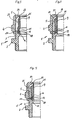
- Fig. 1 einen Teillängsschnitt einer Kabelverschraubung, bei welcher ein Schlauchring als Dichtung von einem Klemmeinsatz und einer Gegenhülse umfaßt und eine Haltehülse einer Schraubhülse stirnseitig übergriffen ist, wobei der Außenumfang der Haltehülse den Schlauchring radial auslenkt,
- Fig. 2 eine der Fig. 1 entsprechende Ausführungsform, bei welcher ein Schlauchring in axialer Richtung unverformt in einem Endbereich von der Haltehülse übergriffen ist,
- Fig. 3
- bis 5 Form-Dichtungen, die von unterschiedlich ausgebildeten Haltehülsen in einem Endbereich gehalten und übergriffen sind,
- Fig. 6
- und 7 weitere Beispiele von Form-Dichtungen mit jeweils verschieden gestalteten Haltehülsen und abgewandelten Endbereichen der Dichtungen, die von diesen Haltehülsen übergriffen sind,
- Fig. 8
- bis 10 Kabelverschraubungen, bei denen die Haltehülse nachträglich als separates Teil eingesetzt und an einem Absatz der Schraubhülse axial abgestützt ist,
- Fig.11
- bis 14 Kabelverschraubungen, bei denen Schlauchringdichtungen im Bereich der Haltehülse radial verformt sind und benachbart dazu an mehreren, wenigstens zwei Klemmstellen beaufschlagt werden.
- 1 is a partial longitudinal section of a cable gland, in which a hose ring as a seal comprises a clamping insert and a counter sleeve and a holding sleeve of a screw sleeve is overlapped on the end face, the outer circumference of the holding sleeve deflecting the hose ring radially,
- 2 shows an embodiment corresponding to FIG. 1, in which a tube ring in the axial direction is overlapped in an end region by the holding sleeve,
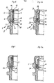
- Fig. 3
- up to 5 molded seals which are held and overlapped in one end area by differently designed holding sleeves,
- Fig. 6
- and 7 further examples of molded seals, each with differently shaped holding sleeves and modified end regions of the seals, which are overlapped by these holding sleeves,
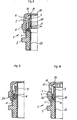
- Fig. 8
- up to 10 cable glands in which the holding sleeve is subsequently used as a separate part and is axially supported on a shoulder of the screw sleeve,
- Fig. 11
- up to 14 cable glands in which hose ring seals are radially deformed in the area of the holding sleeve and are acted upon at several, at least two clamping points adjacent thereto.
Eine in allen Ausführungsbeispielen mit 1 bezeichnete Kabelverschraubung weist jeweils eine Schraubhülse 2 und eine damit mittels Gewinde 3 verbindbare Gegenhülse 4 auf, in welcher ein durch die axiale Verschraubung der Schraubhülse 2 und Gegenhülse 4 gegen ein im Inneren angeordneten Kabel oder einen Schutzschlauch befindlicher Klemmeinsatz 5 vorzugsweise aus härterem Werkstoff als der Kabelmantel radial zusammenpreßbar ist. Die Gegenhülse 4 übergreift dabei den Klemmeinsatz 5 mit einer vorzugsweise als Konus ausgebildeten Ringfläche 6 an einer Stirnseite 7, so daß beim Anziehen des Gewindes 3 ein mit axialen, an der stirnseitigen Ringfläche 6 mündenden Schlitzen 8 versehene Bereich des Klemmeinsatzes 5 aufgrund der Wirkung der konischen Ausbildung der Ringfläche 6 und der Stirnseite 7 radial gegen das Kabel od.dgl. hin verformt wird. Dabei ist zwischen Klemmeinsatz 5 und Kabel eine Dichtung 9 in Form eines Dichtringes oder einer Dichtmanschette angeordnet und diese Dichtung 9 wird durch die erwähnte radiale Verformung des Klemmeinsatzes 5 an das Kabel angepreßt. Da bei der Verschraubung des Gewindes 3 eine in axialer Richtung wirksame Relativbewegung im Sinne einer Annäherung der Schraubhülse 2 und der Gegenhülse 4 erfolgt, wird die Dichtung 9 zusätzlich axial beaufschlagt und stützt sich deshalb mit ihrer der Gegenhülse 4 abgewandten Stirnseite 10 an einem Absatz bzw. einer Abstützung 11 der Schraubhülse 2 ab.A cable gland denoted by 1 in all exemplary embodiments has a
Um bei der erwähnten axialen Beanspruchung der Dichtung 9 und insbesondere bei hohen und starken radialen Druckkräften ein Abrutschen von der Abstützung 11 zu vermeiden, ist bei allen Ausführungsbeispielen vorgesehen, daß die Schraubhülse 2 in ihrem Inneren im Bereich der Abstützung 11 für die Dichtung 9 eine mit ihr verbundene, konzentrische, gegenüber der Abstützung 11 in axialer Richtung vorstehende Haltehülse 12 hat, die die Innenseite 13 des schraubhülsenseitigen Randbereiches 14 der Dichtung 9 übergreift und am Abrutschen von der Abstützung 11 hindert. Man erkennt deutlich in allen Ausführungsbeispielen die Haltehülse 11, die den Randbereich 14 der Dichtung 9 im Inneren über eine gewisse Länge übergreift und so bei axialer Druckbeaufschlagung an einer radialen Verformung nach innen hindert. Somit kann weder ein teilweises noch vollständiges Abrutschen von der Abstützung 11 erfolgen, was insbesondere dann der Fall wäre, wenn das Kabel mit seiner Außenabmessung an der untersten Grenze läge, die von der Kabelverschraubung 1 noch erfaßt werden kann und ein bestimmter Luft- oder Wasserdruck sich über die Schlitze des Klemmeinsatzes aufbauend in radialer Richtung wirksam wird. Der Dichteinsatz wird unter solchen Bedingungen auch dann vond er Abstützung 11 nach innen weggedrückt, wenn diese Abstützung 11 in ihrer Auflagefläche nicht plan sondern schräg ausgeführt ist, so daß ein Hohlraum entsteht. In den Ausführungsbeispielen nach den Figuren 1 bis 7 und 11 bis 14 ist die Haltehülse 12 mit der Schraubhülse 2 einstückig verbunden. Dies bietet sich sowohl bei einer Schraubhülse 2 aus Kunststoff als auch aus Metall an und erhöht deren Herstellungsaufwand praktisch nicht.In order to avoid slipping off of the
Bei den Ausführungsbeispielen nach Fig. 1,2,4,8 sowie 11 bis 13 entspricht der radiale Abstand zwischen der Außenseite der Haltehülse 12 und der Innenseite der Kabelverschraubung 1 zumindest bereichsweise der Dicke der Dichtung 9 in ihrem Endbereich 14. Dieser Endbereich 14 wird bei den erwähnten Ausführungsbeispielen somit gleichermaßen innen und außen umfaßt und entsprechend sicher gehalten. Dabei kann bei axialer Beaufschlagung eine zunächst lockere Steckverbindung durch die Stauchung der Dichtung 9 zu einer entsprechend festen Verbindung werden.In the exemplary embodiments according to FIGS. 1, 2, 4, 8 and 11 to 13, the radial distance between the outside of the holding
Während in den Ausführungsbeispielen gemäß Fig.1,2 sowie 11 bis 14 Schlauchringe als Dichtung 9 vorgesehen sind, deren Querschnitt über die gesamte axiale länge im wesentlichen gleich bleibt, zeigen die Figuren 3 bis 9 Ausführungsbeispiele, bei denen die Dichtung 9 im Bereich der Haltehülse 12 einen Absatz 15 aufweist, der gegen die Stirnseite 16 der Haltehülse 12 anliegen kann, und daß die von diesem Absatz 15 ausgehende Fortsetzung 17 der Dichtung 9 zwischen Haltehülse 12 und Schraubhülse 2 greift. Dadurch wird die Dichtung 9 noch besser in axialer Richtung abgestützt und kann insbesondere in ihrem nicht die Haltehülse 12 hintergreifenden Bereich eine größere Dicke haben, wenn dies für eine größere Toleranz beim Erfassen unterschiedlich"dicker Kabel erwünscht ist oder entsprechend hohe Dichtungsdrücke aufgebracht werden sollen.While in the exemplary embodiments according to FIGS. 1, 2 and 11 to 14, hose rings are provided as the
Fig. 10 ist ein Beispiel dafür, daß die Dichtung 9 über ihre gesamte Länge, wie auch bei dem Ausführungsbeispiel nach Fig. 2, im wesentlichen einen gleichbleibenden ringförmigen Querschnitt haben kann. Zusätzlich ist dabei in diesem Ausführungsbeispiel die Dichtung 9 im Bereich der Haltehülse 12 radial nach außen aufgeweitet. Sie erhält dann bei axialer Beaufschlagung in diesem Bereich sogar eine nach außen gerichtete Komponente, die also von dem inneren Ringspalt zwischen Haltehülse 12 und Kabel weggerichtet ist.FIG. 10 is an example of how the
Sowohl die vorerwähnte Fig. 10 als aber auch die Figuren 3,5,6,7,13 und 14 zeigen, daß der Außenmantel der Haltehülse 12 konisch sein kann.Both the aforementioned Fig. 10 and Figures 3,5,6,7,13 and 14 show that the outer jacket of the holding
Gemäß Fig. 3 und 5 bis 7 steigt dabei die radial äußere, die Dichtung 9 untergreifende Mantelfläche der Haltehülse 12 von ihrem Ansatz bzw. dem Abstützbereich 11 für die Dichtung 9 ausgehend von innen nach außen von einem kleineren zu einem größeren Durchmesser an. Bei den Figuren 3, 5 und 6 ist dabei zwischen der Schraubhülse 2 und der Haltehülse 12 eine sich zur Abstützung der Dichtung 9 erweiternde ringförmige Kammer 18 gebildet. In diese sich erweiternde Kammer 18 kann sich der Endbereich 14 der Dichtung 9 bei axialer Beaufschlagung hineinverformen, um eine noch bessere Verankerung zu ergeben.According to FIGS. 3 and 5 to 7, the radially outer circumferential surface of the holding
Bei den Figuren 9, 10 und 14 verkleinert sich der Außendurchmesser der Haltehülse 12 von der Abstützung 11 der Dichtung 9 ausgehend. Dies ergibt die schon erwähnte von dem Spalt zwischen Hülse 12 und Kabel wegführende Komponente bei axialer Beaufschlagung der Dichtung 9.In FIGS. 9, 10 and 14, the outer diameter of the holding
Es sei noch erwähnt, daß Fig. 7 ein Beispiel dafür ist, daß die Außenseite der Haltehülse 12 in beiden Richtungen konisch verlaufen kann, indem sie zunächst von der Abstützung 11 ausgehend ihren Durchmesser verkleinert und dann wieder vergrößert.It should also be mentioned that FIG. 7 is an example of the fact that the outside of the holding
Fig. 8 bis 10 zeigt Möglichkeiten, die Haltehülse 12 nachträglich in die Kabelverschraubung 1 einsetzbar vorzusehen und vorzugsweise an einem inneren Absatz 19 derFig. 8 to 10 shows ways to provide the holding
Schraubhülse 2 insbesondere in axialer Richtung formschlüssig festzulegen. Diese Lösung bietet sich an, wenn die Schraubhülse aus Metall besteht, zusätzlich aber die Haltehülse 12 zur inneren Isolierung der Schraubhülse dienen soll. Dies-ist bei allen drei Ausführungsbeispielen dadurch realisiert, daß die Haltehülse 12 eine von der Dichtung 9 abgewandte Fortsetzung als Isolierhülse 20 hat, die in axialer Richtung bis zu dem der Gegenhülse 3 abgewandten Ende der Schraubhülse 2 reicht.Specify
Diese nachträglich einsetzbare Haltehülse 2 erfüllt also eine Doppelfunktion, indem sie einerseits die Innenseite des stirnseitigen Randbereiches 14 der Dichtung 9 übergreift und sichert und andererseits die Innenseite der Schraubhülse 2 isoliert. Eine ganz spezielle Ausgestaltung zeigt dabei Fig. 8, bei welcher die Haltehülse 12 mit Schlitzen 8 versehen eine die Dichtung 9 auch an deren Außenseite umgreifende Fortsetzung 21 hat, die dabei gleichzeitig als Axialschlitz 8 aufweisender Klemmeinsatz 5 ausgebildet ist. Praktisch ist in diesem Falle die Haltehülse 12 als ein zusätzlicher Klemmeinsatz 5 einstükkig mit dem Klemmeinsatz 5 verbunden, was schon eine vorteilhafte Ausgestlatung der Erfindung sein kann. Zusätzlich ist dann noch die Isolierhülse 20 angeformt. Somit kann mit einem einzigen Einsatzteil die Kabelverschraubung 1 gemäß Fig. 8 mit zwei Klemmeinsätzen 5, Haltehülse 12 und Isolierhülse 20 versehen werden.This subsequently usable holding
Eine andere Möglichkeit ist beispielsweise in Fig. 6 bis 7a, 9 und 10 oder 14 angedeutet. In diesem Falle ragt der die Dichtung 9 übergreifende Randbereich der Haltehülse 12 teilweise unter den Klemmbereich des die Dichtung 9 auf seiner sich nach außen erstreckenden ringförmigen Erweiterung 26 beaufschlagenden Klemmeinsatzes 5, also in den Bereich des entsprechend zur ringförmigen Erweiterung 26 geformten Klemmeinsatzes 5, in den auch die Schlitze 8 ragen. Dadurch wird die Dichtung auch an der Außenseite der Haltehülse 12 angedrückt und dadurch besser gekammert und gehalten.Another possibility is indicated, for example, in FIGS. 6 to 7a, 9 and 10 or 14. In this case, the edge region of the holding
Die Form der Dichtung 9 im Bereich ihrer Abstützung 11 und Übergreifung durch die Haltehülse 12 kann dabei dem ringförmigen Hohlraum zwischen der Haltehülse 12 und der Schraubhülse 2 entsprechend, also als Formdichtung ausgebildet sein. Dies erkennt man deutlich in den Figuren 8 und 10 oder auch in den Figuren 11 bis 14 sowie in einfacher Form in Fig.1 oder 2 oder auch 4. Es wäre aber auch möglich, die entsprechenden Endbereiche der Dichtung 9 an die Form der Kammer 18 beispielsweise des Ausführungsbeispiels nach Fig. 3 anpassen und eine entsprechende Formdichtung zu schaffen, die beim Einsetzen in diese Kammer eingezwängt werden müßte.The shape of the
In den Figuren 1 und 3 bis 10 wird gezeigt, wie die Dichtigkeit der Kabelverschraubung zwischen Dichteinsatz 9 und Kabeloberfläche entsprechend gesteigert und erhalten werden kann. Dazu ist es notwendig, daß der Klemmeinsatz 5 den Dichteinsatz 9 stirnseitig maximal dreiviertel seiner Wandstärke übergreift, so daß der Dichteinsatz zwar durch die Übergreifung 24 am Davonkriechen gehindert, die Kabeloberfläche aber durch die Übergreifung 24 nicht beschädigt wird.FIGS. 1 and 3 to 10 show how the tightness of the cable gland between the sealing
Nach Fig. 3 bis 7 und 8 und 9 ergibt sich eine weitere Verbesserung dadurch, daß der Dichteinsatz 9 auf seiner der Gegenhülse 4 zugewandten Seite 22 einen Absatz 25 aufweist, welcher mit seinem Ansatz durch die Übergreifung 24 des Klemmeinsatzes 5 hindurchführt und auch beim Abbiegen des Kabels sich schützend zwischen die Klemmfinger 23 des Klemmeinsatzes 5 und der Kabeloberfläche legt, so daß das Kabel nicht beschädigt und der durch. die Absetzung gekammerte Dichtwerkstoff auch nicht bei Zugbelastung davonkriechen kann.According to FIGS. 3 to 7 and 8 and 9, there is a further improvement in that the sealing
Alle in der Beschreibung, der Zusammenfassung, den Ansprüchen und der Zeichnung dargestellten Merkmale und Konstruktionsdetails können sowohl einzeln als auch in beliebiger Kombination miteinander wesentliche Bedeutung haben.All features and construction details shown in the description, the summary, the claims and the drawing can have significant meaning both individually and in any combination with one another.
Claims (19)
Applications Claiming Priority (2)
| Application Number | Priority Date | Filing Date | Title |
|---|---|---|---|
| DE3519032 | 1985-05-25 | ||
| DE3519032A DE3519032C1 (en) | 1985-05-25 | 1985-05-25 | Cable gland with a clamping insert and a seal |
Publications (3)
| Publication Number | Publication Date |
|---|---|
| EP0203263A2 true EP0203263A2 (en) | 1986-12-03 |
| EP0203263A3 EP0203263A3 (en) | 1987-10-21 |
| EP0203263B1 EP0203263B1 (en) | 1992-04-15 |
Family
ID=6271771
Family Applications (1)
| Application Number | Title | Priority Date | Filing Date |
|---|---|---|---|
| EP86101943A Expired - Lifetime EP0203263B1 (en) | 1985-05-25 | 1986-02-15 | Screw-threaded cable fitting with clamping and sealing means |
Country Status (2)
| Country | Link |
|---|---|
| EP (1) | EP0203263B1 (en) |
| DE (2) | DE3519032C1 (en) |
Cited By (10)
| Publication number | Priority date | Publication date | Assignee | Title |
|---|---|---|---|---|
| FR2611322A1 (en) * | 1987-02-19 | 1988-08-26 | Conducto | Sealing and clamping device for cables |
| US5207602A (en) * | 1989-06-09 | 1993-05-04 | Raychem Corporation | Feedthrough coaxial cable connector |
| US5277598A (en) * | 1992-07-10 | 1994-01-11 | Raychem Corporation | Coaxial cable connection protection system with multiple chambered shroud |
| US5297972A (en) * | 1992-07-10 | 1994-03-29 | Raychem Corporation | Coaxial cable connection protection system |
| US5362250A (en) * | 1992-11-25 | 1994-11-08 | Raychem Corporation | Coaxial cable connection method and device using oxide inhibiting sealant |
| US5435736A (en) * | 1993-09-07 | 1995-07-25 | Raychem Corporation | Coaxial cable connection protection system for unused connection port |
| US5486120A (en) * | 1992-07-10 | 1996-01-23 | Raychem Corporation | Coaxial cable connection protection system with multiple chambered, flexible-webbed shroud |
| ITMI20130472A1 (en) * | 2013-03-28 | 2014-09-29 | Gewiss Spa | CABLE STRUCTURE, PARTICULARLY FOR INDUSTRIAL SOCKETS AND PLUGS |
| WO2018019325A1 (en) * | 2016-07-25 | 2018-02-01 | Pflitsch Gmbh & Co. Kg | Device for the sealed passing-through of an elongate part |
| EP3787123A1 (en) | 2019-08-28 | 2021-03-03 | Etel S. A.. | Cable shield connecting assembly for electrical device and method for securing and grounding a cable to a cylindrical housing of an electric rotary motor |
Families Citing this family (2)
| Publication number | Priority date | Publication date | Assignee | Title |
|---|---|---|---|---|
| DE202007003957U1 (en) | 2007-03-19 | 2008-07-31 | Anton Hummel Verwaltungs-Gmbh | Cable gland with threaded sleeve and union nut |
| DE102015006521A1 (en) | 2015-05-26 | 2016-12-01 | Jacob Gmbh Elektrotechnische Fabrik | Device for attaching a pipe |
Citations (3)
| Publication number | Priority date | Publication date | Assignee | Title |
|---|---|---|---|---|
| FR2358766A1 (en) * | 1976-07-16 | 1978-02-10 | Lapp Kg Ui | DEVICE FOR MAINTAINING CABLES, ELECTRICAL LINES, PIPES AND SIMILAR |
| DE3104974A1 (en) * | 1981-02-12 | 1982-09-16 | U.I. Lapp Kg, 7000 Stuttgart | Insert for screwed connections |
| US4544800A (en) * | 1982-12-25 | 1985-10-01 | Nikko Kogyo Kabushiki Kaisha | Cable holder |
Family Cites Families (1)
| Publication number | Priority date | Publication date | Assignee | Title |
|---|---|---|---|---|
| DE1750095A1 (en) * | 1968-03-29 | 1971-03-11 | Walter Roehl | Screw connection for cables, hoses, etc. |
-
1985
- 1985-05-25 DE DE3519032A patent/DE3519032C1/en not_active Expired
-
1986
- 1986-02-15 EP EP86101943A patent/EP0203263B1/en not_active Expired - Lifetime
- 1986-02-15 DE DE8686101943T patent/DE3684815D1/en not_active Expired - Lifetime
Patent Citations (3)
| Publication number | Priority date | Publication date | Assignee | Title |
|---|---|---|---|---|
| FR2358766A1 (en) * | 1976-07-16 | 1978-02-10 | Lapp Kg Ui | DEVICE FOR MAINTAINING CABLES, ELECTRICAL LINES, PIPES AND SIMILAR |
| DE3104974A1 (en) * | 1981-02-12 | 1982-09-16 | U.I. Lapp Kg, 7000 Stuttgart | Insert for screwed connections |
| US4544800A (en) * | 1982-12-25 | 1985-10-01 | Nikko Kogyo Kabushiki Kaisha | Cable holder |
Cited By (19)
| Publication number | Priority date | Publication date | Assignee | Title |
|---|---|---|---|---|
| FR2611322A1 (en) * | 1987-02-19 | 1988-08-26 | Conducto | Sealing and clamping device for cables |
| US5207602A (en) * | 1989-06-09 | 1993-05-04 | Raychem Corporation | Feedthrough coaxial cable connector |
| US5609501A (en) * | 1989-06-09 | 1997-03-11 | Raychem Corporation | Feed through coaxial cable connector |
| US5486120A (en) * | 1992-07-10 | 1996-01-23 | Raychem Corporation | Coaxial cable connection protection system with multiple chambered, flexible-webbed shroud |
| US5277598A (en) * | 1992-07-10 | 1994-01-11 | Raychem Corporation | Coaxial cable connection protection system with multiple chambered shroud |
| US5297972A (en) * | 1992-07-10 | 1994-03-29 | Raychem Corporation | Coaxial cable connection protection system |
| US5469613A (en) * | 1992-07-10 | 1995-11-28 | Raychem Corporation | Tool for connecting a coaxial cable terminus to a connection jack |
| US5490803A (en) * | 1992-11-25 | 1996-02-13 | Raychem Corporation | Coaxial cable connection method and device using oxide inhibiting sealant |
| US5362250A (en) * | 1992-11-25 | 1994-11-08 | Raychem Corporation | Coaxial cable connection method and device using oxide inhibiting sealant |
| US5435736A (en) * | 1993-09-07 | 1995-07-25 | Raychem Corporation | Coaxial cable connection protection system for unused connection port |
| US5655915A (en) * | 1993-09-07 | 1997-08-12 | Raychem Corporation | Coaxial cable connection protection system for unused connection port |
| ITMI20130472A1 (en) * | 2013-03-28 | 2014-09-29 | Gewiss Spa | CABLE STRUCTURE, PARTICULARLY FOR INDUSTRIAL SOCKETS AND PLUGS |
| EP2784887A1 (en) * | 2013-03-28 | 2014-10-01 | GEWISS S.p.A. | Cable gland assembly for electrical apparatus |
| CN104078792A (en) * | 2013-03-28 | 2014-10-01 | 哥维斯股份公司 | Cable gland assembly used for electrical appliance |
| CN104078792B (en) * | 2013-03-28 | 2018-05-15 | 哥维斯股份公司 | Cable connector assembly and the electrical equipment including cable connector assembly |
| WO2018019325A1 (en) * | 2016-07-25 | 2018-02-01 | Pflitsch Gmbh & Co. Kg | Device for the sealed passing-through of an elongate part |
| EA037566B1 (en) * | 2016-07-25 | 2021-04-14 | Пфлич Гмбх Унд Ко. Кг | Device for the sealed passing-through of an elongate part |
| US11598417B2 (en) | 2016-07-25 | 2023-03-07 | Pflitsch Gmbh & Co. Kg | Device for the sealed passing-through of an elongate part |
| EP3787123A1 (en) | 2019-08-28 | 2021-03-03 | Etel S. A.. | Cable shield connecting assembly for electrical device and method for securing and grounding a cable to a cylindrical housing of an electric rotary motor |
Also Published As
| Publication number | Publication date |
|---|---|
| EP0203263B1 (en) | 1992-04-15 |
| EP0203263A3 (en) | 1987-10-21 |
| DE3684815D1 (en) | 1992-05-21 |
| DE3519032C1 (en) | 1986-10-30 |
Similar Documents
| Publication | Publication Date | Title |
|---|---|---|
| DE2902174C2 (en) | Device for attaching cables or the like to a support part | |
| DE3216938C2 (en) | Pipe connection | |
| EP2054977B1 (en) | Plug connector for front plate or back plate assembly | |
| EP0203263B1 (en) | Screw-threaded cable fitting with clamping and sealing means | |
| DE2802937A1 (en) | ARRANGEMENT FOR RETRACTING A SLEEVE PIPE CONNECTION | |
| EP0203269B1 (en) | Screw-threaded cable fitting | |
| DE4238517A1 (en) | Cable gland for grounding or shielding cables | |
| DE1963299C3 (en) | Connection for at least one pressurized, tubular element having a smooth end | |
| EP0165414A2 (en) | Screw-threaded cable fitting | |
| DE102012102415B4 (en) | Mounting system for pipe fittings with cutting ring | |
| EP0159385A1 (en) | Sealing ring, sleeve with a sealing ring and its use | |
| DE20214631U1 (en) | Adapter intermediate ring for a screw-in part of a fluid connector system | |
| EP3726267B1 (en) | Single raw seal and plastic pipe | |
| DE102017212009A1 (en) | strain relief | |
| EP2716824A2 (en) | Hose, in particular a shower hose | |
| DE1943885B2 (en) | Connection element for two electromagnetic waveguides | |
| CH682175A5 (en) | Connection for domestic piping - has fitting to which cylindrical protective socket is releasably fixed, socket covering connection onto which one end of union pipe is pushed | |
| DE102012212023A1 (en) | Cable conduit fitting, has connecting piece inserted into housing opening, and clamping body arranged within sealing element and loaded with pressing forces, where pressing forces are transferred to additional sealing element over body | |
| DE2513982B2 (en) | PIPE SEAL | |
| DE3031687C2 (en) | Device for protecting the end areas of pipes against mechanical damage | |
| EP0640786B1 (en) | Combined threaded connection for cable and hose | |
| DE202011004544U1 (en) | Press connection for plastic pipes | |
| DE3731222C2 (en) | ||
| EP2650576B1 (en) | Double nipple for the sealed laying of long moulded parts | |
| DE19512464A1 (en) | Compression fitting with opening for pipe union with conduit |
Legal Events
| Date | Code | Title | Description |
|---|---|---|---|
| PUAI | Public reference made under article 153(3) epc to a published international application that has entered the european phase |
Free format text: ORIGINAL CODE: 0009012 |
|
| AK | Designated contracting states |
Kind code of ref document: A2 Designated state(s): CH DE FR GB IT LI |
|
| PUAL | Search report despatched |
Free format text: ORIGINAL CODE: 0009013 |
|
| AK | Designated contracting states |
Kind code of ref document: A3 Designated state(s): CH DE FR GB IT LI |
|
| 17P | Request for examination filed |
Effective date: 19880324 |
|
| 17Q | First examination report despatched |
Effective date: 19900925 |
|
| RAP1 | Party data changed (applicant data changed or rights of an application transferred) |
Owner name: ANTON HUMMEL VERWALTUNGS-GMBH |
|
| GRAA | (expected) grant |
Free format text: ORIGINAL CODE: 0009210 |
|
| AK | Designated contracting states |
Kind code of ref document: B1 Designated state(s): CH DE FR GB IT LI |
|
| REF | Corresponds to: |
Ref document number: 3684815 Country of ref document: DE Date of ref document: 19920521 |
|
| ITF | It: translation for a ep patent filed |
Owner name: ING. ZINI MARANESI & C. S.R.L. |
|
| ET | Fr: translation filed | ||
| GBT | Gb: translation of ep patent filed (gb section 77(6)(a)/1977) | ||
| PLBE | No opposition filed within time limit |
Free format text: ORIGINAL CODE: 0009261 |
|
| STAA | Information on the status of an ep patent application or granted ep patent |
Free format text: STATUS: NO OPPOSITION FILED WITHIN TIME LIMIT |
|
| 26N | No opposition filed | ||
| REG | Reference to a national code |
Ref country code: GB Ref legal event code: IF02 |
|
| PGFP | Annual fee paid to national office [announced via postgrant information from national office to epo] |
Ref country code: FR Payment date: 20041229 Year of fee payment: 20 |
|
| PGFP | Annual fee paid to national office [announced via postgrant information from national office to epo] |
Ref country code: DE Payment date: 20050201 Year of fee payment: 20 |
|
| PGFP | Annual fee paid to national office [announced via postgrant information from national office to epo] |
Ref country code: GB Payment date: 20050208 Year of fee payment: 20 |
|
| PGFP | Annual fee paid to national office [announced via postgrant information from national office to epo] |
Ref country code: CH Payment date: 20050218 Year of fee payment: 20 |
|
| PGFP | Annual fee paid to national office [announced via postgrant information from national office to epo] |
Ref country code: IT Payment date: 20050225 Year of fee payment: 20 |
|
| PG25 | Lapsed in a contracting state [announced via postgrant information from national office to epo] |
Ref country code: GB Free format text: LAPSE BECAUSE OF EXPIRATION OF PROTECTION Effective date: 20060214 |
|
| REG | Reference to a national code |
Ref country code: GB Ref legal event code: PE20 |
|
| REG | Reference to a national code |
Ref country code: CH Ref legal event code: PL |