EP0202105A2 - Scanning microscope - Google Patents
Scanning microscope Download PDFInfo
- Publication number
- EP0202105A2 EP0202105A2 EP86303622A EP86303622A EP0202105A2 EP 0202105 A2 EP0202105 A2 EP 0202105A2 EP 86303622 A EP86303622 A EP 86303622A EP 86303622 A EP86303622 A EP 86303622A EP 0202105 A2 EP0202105 A2 EP 0202105A2
- Authority
- EP
- European Patent Office
- Prior art keywords
- stage
- support frame
- springs
- plane
- scanning
- Prior art date
- Legal status (The legal status is an assumption and is not a legal conclusion. Google has not performed a legal analysis and makes no representation as to the accuracy of the status listed.)
- Withdrawn
Links
- 230000033001 locomotion Effects 0.000 claims abstract description 27
- 239000000463 material Substances 0.000 claims abstract description 8
- 230000008878 coupling Effects 0.000 claims 2
- 238000010168 coupling process Methods 0.000 claims 2
- 238000005859 coupling reaction Methods 0.000 claims 2
- 230000005540 biological transmission Effects 0.000 description 4
- 230000005855 radiation Effects 0.000 description 4
- 230000003287 optical effect Effects 0.000 description 3
- 238000005096 rolling process Methods 0.000 description 3
- 229910000906 Bronze Inorganic materials 0.000 description 1
- OAICVXFJPJFONN-UHFFFAOYSA-N Phosphorus Chemical compound [P] OAICVXFJPJFONN-UHFFFAOYSA-N 0.000 description 1
- DMFGNRRURHSENX-UHFFFAOYSA-N beryllium copper Chemical compound [Be].[Cu] DMFGNRRURHSENX-UHFFFAOYSA-N 0.000 description 1
- 239000010974 bronze Substances 0.000 description 1
- 230000006835 compression Effects 0.000 description 1
- 238000007906 compression Methods 0.000 description 1
- KUNSUQLRTQLHQQ-UHFFFAOYSA-N copper tin Chemical compound [Cu].[Sn] KUNSUQLRTQLHQQ-UHFFFAOYSA-N 0.000 description 1
- 230000000694 effects Effects 0.000 description 1
- 238000000034 method Methods 0.000 description 1
- 239000012780 transparent material Substances 0.000 description 1
Images


Classifications
-
- G—PHYSICS
- G02—OPTICS
- G02B—OPTICAL ELEMENTS, SYSTEMS OR APPARATUS
- G02B21/00—Microscopes
- G02B21/0004—Microscopes specially adapted for specific applications
- G02B21/002—Scanning microscopes
-
- B—PERFORMING OPERATIONS; TRANSPORTING
- B23—MACHINE TOOLS; METAL-WORKING NOT OTHERWISE PROVIDED FOR
- B23Q—DETAILS, COMPONENTS, OR ACCESSORIES FOR MACHINE TOOLS, e.g. ARRANGEMENTS FOR COPYING OR CONTROLLING; MACHINE TOOLS IN GENERAL CHARACTERISED BY THE CONSTRUCTION OF PARTICULAR DETAILS OR COMPONENTS; COMBINATIONS OR ASSOCIATIONS OF METAL-WORKING MACHINES, NOT DIRECTED TO A PARTICULAR RESULT
- B23Q1/00—Members which are comprised in the general build-up of a form of machine, particularly relatively large fixed members
- B23Q1/25—Movable or adjustable work or tool supports
- B23Q1/26—Movable or adjustable work or tool supports characterised by constructional features relating to the co-operation of relatively movable members; Means for preventing relative movement of such members
- B23Q1/34—Relative movement obtained by use of deformable elements, e.g. piezoelectric, magnetostrictive, elastic or thermally-dilatable elements
- B23Q1/36—Springs
Abstract
Description
- stage, which link member is caused by the motor to reciprocate backwards and forwards in order to cause corresponding movement of the stage with respect to the support frame. The exact form of this reciprocatory movement depends upon the desired pattern of scanning and is not of direct concern to the present invention.
- The link members may need to be jointed in order to allow movement in both the X and Y directions. However, in one embodiment, a further support frame is provided which itself mounts the first support frame by means of further leaf springs. In this latter arrangement the drive means, linear motors or whatever, for each of the X and Y directions can be mounted on a separate support frame which enable a rigid link member to be used and also, incidentally has the advantage that the X motion causes the minimum interference with the Y motion and vice versa.
- The teaching of the invention can be applied to microscopes both of the reflective and of the transmission type. In the latter case, where the radiation passes through the object, the stage is made from radiation-transparent material.
- In order that the invention may be better understood, several embodiments thereof will now be described by way of example only and with reference to the accompanying drawings in which:-
- Figure 1 is a diagrammatic view of an optical scanning microscope of the transmission type showing the layout of the various components; and
- Figures 2 to 5 are diagrammatic views, looking in the Z direction, of a vibratory stage for supporting and scanning the object in the microscope of Figure 1.
- Referring to Figure 1 the basic microscope comprises a
laser source 1 providing a collimatedbeam 2 of radiation. The radiation is brought to a focus at the plane of anobject 3 by means of anobjective lens 4. After transmission through the object, the beam is passed through a further lens 5 which brings it to a focus at a detector 6. The output signal from the detector 6 is amplified and displayed. - Although not shown in Figure 1 for clarity, the
object 3 is mounted on a platform which is moved in the object plane to effect scanning of the object relative to the incident beam, thus enabling a complete picture of the object or part thereof to be built up. Various methods of scanning may be employed, the most common being similar to raster scanning used in conventional TV cathode ray tubes. For correct focussing it is important that the object remains in the object plane during scanning, this being the plane which crosses the optical axis of the microscope at a right angle at the point at which the beam is brought to a focus. For convenience the optical axis is generally referred to as the Z axis with the two mutually orthogonal directions of scanning being the X axis and the Y axis, both in the object plane. It is to be noted, however, that the X and Y axes-do not have to be orthogonal, although orthogonal axes are assumed throughout the present discussion. - The stage and its associated scanning means are shown in more detail in Figures 2 to 5. Referring firstly to Figure 2 there is shown a simple form in which the stage, shown under
reference 7, is movably mounted within a support frame 8 by means of fourleaf springs first connection point 13 to thestage 7 and at a respectivesecond connection point 14, diametrically opposite to the first, to the inside surface of the frame 8. Being leaf springs, it is understood that the springs have depth in the Z-direction. The X and Y directions are shown on the drawing. For each of these directions a respective scanning means is provided. Each scanning means takes the form of a pair of linear motors, 15, 16 for the X direction and 17, 18 for the Y direction. The motors of each pair act oppositely to each other in order to cause scanning movement of thestage 7 in the X-Y plane. To this end each motor is connected to a respective edge of thestage 7 by arespective link member 19 to 22. Each link member comprises a rigidcentral portion 23 and outermostflexible portions 24, the latter comprising a piece of sheet flexible material attached in such a way as to transmit the backwards and forwards movement of the linear motors to thestage 7 and also to allow the link members to pivot in the X-Y plane but not in the Z plane. In order to achieve this the sheets making up theflexible portions 24 lie in a plane parallel to the Z axis. - Each leaf spring is formed from a sheet of flexible material such as beryllium copper or phosphor bronze which is bent into the shape shown and attached in the manner described above. The sheet is bent in such a way that its active part - i.e. the part forming the spring - is tangent to planes parallel to the Z axis. This ensures the minimum of movement of the stage in the Z direction. Clearly however the stage can be moved in any direction within the X-Y plane, this motion being accomplished by either compressing or rolling of the
leaf springs 9 to 12. - Scanning is effected by supplying suitable electrical signals to the linear motors whereupon appropriate movement of the link members and hence the
stage 7 occurs. - For a transmission microscope such as that shown in Figure 1, the
stage 7 is made transparent to the radiation being used. - Reference is now made to Figure 3 which shows a second embodiment of the
vibratory stage 7. In this case the stage ; RE meunted by means ofleaf springs 25 such as those described above on a first mounting frame 2b which is itself mounted within a second mountingframe 27 byfurther leaf springs 28. Attached to theinner frame 26 are thelinear motors outer frame 27 are thelinear motors Apertures 33 are formed in theouter frame 27 to accommodate thelinear motors 15 and lb and allow the full range of movement thereof relative to the outer frame. In the case of the X direction motion is transmitted from thelinear motors stage 7 vialink members stage 7 andinner frame 26 in the Y direction). In the case of the Y direction motion is transmitted from thelinear motors stage 7 vialink members inner frame 26 and thence viasprings 25 to the stage. - The advantage of this arrangement over that described in relation to Figure 2 is that the X motion does not interfere with the Y motion and vice versa. Also it should be noted that the rate of the leaf springs when compressed across their diameter is greater than when they are rolled. It is therefore possible to obtain greater control over the stage as in each case the X and Y motions are made against the rolling direction of the respective springs and not, as in Figure 2, against some springs in rolling mode and others in diametric compression. The arrangement of Figure 3 also dispenses with the need for flexible link members between the motors and the moving elements.
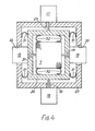
- Figure 4 illustrates an arrangement similar to that of Figure 3 but in which the circular leaf springs are replaced by C-shaped leaf springs.
Springs 31 mount the inner frame within the outer frame and are each attached at one end to the inner frame and at the other end to the outer frame;springs 32 mount thestage 7 within the inner frame and are each attached at one end to the stage and at the other end to the inner frame. - Figure 5 illustrates an arrangement similar to that of Figure 2 but in which the springs are placed at the corners of the support frame 8, the
stage 7 being conveniently of round shape. This arrangement provides a more even spring rate in the various possible directions of movement within the X-Y plane. - In all cases, some care needs to be taken in the design of the stage support springs. For example the greater the width of the springs - i.e. the greater their extent in the Z direction - the greater their resistance to twisting and therefore the greater the resistance of the stage to movement along the Z axis. Resistance to Z axis movement can also be increased by the simple expedient of making the sheet material from which the springs are made thicker. However this at the same time increases the rate of the springs and hence the power needed to move the stage. A compromise must therefore be reached between acceptable stiffness in the springs as against the power needed to be exerted by the linear motors to move the stage. To this end the use in all of the described embodiments of linear motors for each direction of scanning assists in that more power is available to move the stage.
Claims (7)
Applications Claiming Priority (2)
| Application Number | Priority Date | Filing Date | Title |
|---|---|---|---|
| GB858512045A GB8512045D0 (en) | 1985-05-13 | 1985-05-13 | Scanning microscope |
| GB8512045 | 1985-05-13 |
Publications (2)
| Publication Number | Publication Date |
|---|---|
| EP0202105A2 true EP0202105A2 (en) | 1986-11-20 |
| EP0202105A3 EP0202105A3 (en) | 1989-04-12 |
Family
ID=10579048
Family Applications (1)
| Application Number | Title | Priority Date | Filing Date |
|---|---|---|---|
| EP86303622A Withdrawn EP0202105A3 (en) | 1985-05-13 | 1986-05-13 | Scanning microscope |
Country Status (3)
| Country | Link |
|---|---|
| EP (1) | EP0202105A3 (en) |
| JP (1) | JPS6217723A (en) |
| GB (1) | GB8512045D0 (en) |
Cited By (4)
| Publication number | Priority date | Publication date | Assignee | Title |
|---|---|---|---|---|
| US6137627A (en) * | 1996-08-23 | 2000-10-24 | Leica Microsystems Heidelberg Gmbh | Fine focusing table |
| EP1113301A2 (en) * | 1999-11-24 | 2001-07-04 | Leica Microsystems Heidelberg GmbH | Device for beam deflection |
| US6467761B1 (en) * | 1999-06-21 | 2002-10-22 | The United States Of America As Represented By The Secretary Of Commerce | Positioning stage |
| DE19520606B4 (en) * | 1995-06-06 | 2004-04-08 | Roche Diagnostics Gmbh | Device for the optical examination of surfaces |
Families Citing this family (3)
| Publication number | Priority date | Publication date | Assignee | Title |
|---|---|---|---|---|
| JPH03168713A (en) * | 1989-11-29 | 1991-07-22 | Fuji Photo Film Co Ltd | Scanning type microscope |
| JPH0552811U (en) * | 1991-12-20 | 1993-07-13 | オリンパス光学工業株式会社 | Optical microscope |
| JP2007057256A (en) * | 2005-08-22 | 2007-03-08 | Jeol Ltd | Xy stage |
Citations (3)
| Publication number | Priority date | Publication date | Assignee | Title |
|---|---|---|---|---|
| DE3243890A1 (en) * | 1981-11-26 | 1983-06-09 | The Secretary of State for Defence in Her Britannic Majesty's Government of the United Kingdom of Great Britain and Northern Ireland Whitehall, London | IMAGE SYSTEM |
| JPS60107613A (en) * | 1983-11-16 | 1985-06-13 | Matsushita Electric Ind Co Ltd | Sample stage for microscope |
| EP0149017A2 (en) * | 1983-12-30 | 1985-07-24 | International Business Machines Corporation | Piezoelectric X-Y positioner |
-
1985
- 1985-05-13 GB GB858512045A patent/GB8512045D0/en active Pending
-
1986
- 1986-05-13 JP JP10935486A patent/JPS6217723A/en active Pending
- 1986-05-13 EP EP86303622A patent/EP0202105A3/en not_active Withdrawn
Patent Citations (3)
| Publication number | Priority date | Publication date | Assignee | Title |
|---|---|---|---|---|
| DE3243890A1 (en) * | 1981-11-26 | 1983-06-09 | The Secretary of State for Defence in Her Britannic Majesty's Government of the United Kingdom of Great Britain and Northern Ireland Whitehall, London | IMAGE SYSTEM |
| JPS60107613A (en) * | 1983-11-16 | 1985-06-13 | Matsushita Electric Ind Co Ltd | Sample stage for microscope |
| EP0149017A2 (en) * | 1983-12-30 | 1985-07-24 | International Business Machines Corporation | Piezoelectric X-Y positioner |
Non-Patent Citations (4)
| Title |
|---|
| ELECTRONICS & POWER, February 1980, pages 166-172, IEE, GB; C.J.R. SHEPPARD: "Scanning optical microscope" * |
| IBM TECHNICAL DISCLOSURE BULLETIN, vol. 22, no. 7, December 1979, pages 2930-2931, New York, US; W.B. PENNEBAKER: "Spatially linear motion device for printers and scanners" * |
| PATENT ABSTRACTS OF JAPAN, vol. 9, no. 257 (P-396)[1980], 15th October 1985; & JP-A-60 107 613 (MATSUSHITA DENKI SANGYO K.K.) 13-06-1985 * |
| ULTRASONICS SYMPOSIUM PROCEEDINGS, Atlanta, Georgia, 31st October - 2nd November 1983, vol. 2, pages 605-610, IEEE, New York, US; R.A. HARVEY et al.: "A miniature lens scanner for acoustic microscopy" * |
Cited By (5)
| Publication number | Priority date | Publication date | Assignee | Title |
|---|---|---|---|---|
| DE19520606B4 (en) * | 1995-06-06 | 2004-04-08 | Roche Diagnostics Gmbh | Device for the optical examination of surfaces |
| US6137627A (en) * | 1996-08-23 | 2000-10-24 | Leica Microsystems Heidelberg Gmbh | Fine focusing table |
| US6467761B1 (en) * | 1999-06-21 | 2002-10-22 | The United States Of America As Represented By The Secretary Of Commerce | Positioning stage |
| EP1113301A2 (en) * | 1999-11-24 | 2001-07-04 | Leica Microsystems Heidelberg GmbH | Device for beam deflection |
| EP1113301A3 (en) * | 1999-11-24 | 2001-11-21 | Leica Microsystems Heidelberg GmbH | Apparatus for light beam deflection |
Also Published As
| Publication number | Publication date |
|---|---|
| JPS6217723A (en) | 1987-01-26 |
| EP0202105A3 (en) | 1989-04-12 |
| GB8512045D0 (en) | 1985-06-19 |
Similar Documents
| Publication | Publication Date | Title |
|---|---|---|
| DE3103010C2 (en) | ||
| US20030174418A1 (en) | Linear guiding mechanism | |
| DE3942771C1 (en) | ||
| EP0174091A1 (en) | Stereo Camera | |
| DE112013006119T5 (en) | Optical scanner and projector | |
| EP0202105A2 (en) | Scanning microscope | |
| DE2849336A1 (en) | SYSTEM FOR DYNAMIC IMAGE IMPROVEMENT OF A FIBERSCOPE | |
| CN1886088A (en) | Variable view arthroscope with charge coupled device | |
| EP2491451B1 (en) | Device and method for deflecting a light beam in two different directions and scanning microscope | |
| KR20020023142A (en) | Gimbal mechanism | |
| US4615591A (en) | Mechanical positioning device for scientific instruments | |
| US4378952A (en) | Dynamic image enhancer for fiberscopes | |
| EP0699929A1 (en) | Positioning device for optical fiber splicer | |
| US4405950A (en) | Television display system handling and adjustment apparatus | |
| CN110850588A (en) | Optical fiber scanner | |
| US4641335A (en) | Primary-beam collimator for stereo radiographic x-ray diagnostic apparatus | |
| US3714423A (en) | Specimen stages for electron microscopes | |
| US4445498A (en) | Support arm for a sunlight concentrating and collecting apparatus | |
| JP2525152Y2 (en) | Optical distribution device for X-ray diagnostic equipment | |
| CN107003615B (en) | Projection optical system, exposure device and device making method | |
| JP2794923B2 (en) | Optical equipment having a lens moving device | |
| DE2802950C2 (en) | ||
| CN216526405U (en) | Micro-lens coupling optical path system and micro-lens coupling device | |
| US6853608B1 (en) | Optical pickup apparatus and method of manufacturing the same | |
| JP2946366B2 (en) | Zoom lens device |
Legal Events
| Date | Code | Title | Description |
|---|---|---|---|
| PUAI | Public reference made under article 153(3) epc to a published international application that has entered the european phase |
Free format text: ORIGINAL CODE: 0009012 |
|
| AK | Designated contracting states |
Kind code of ref document: A2 Designated state(s): AT BE CH DE FR GB IT LI LU NL SE |
|
| PUAL | Search report despatched |
Free format text: ORIGINAL CODE: 0009013 |
|
| STAA | Information on the status of an ep patent application or granted ep patent |
Free format text: STATUS: THE APPLICATION IS DEEMED TO BE WITHDRAWN |
|
| AK | Designated contracting states |
Kind code of ref document: A3 Designated state(s): AT BE CH DE FR GB IT LI LU NL SE |
|
| 18D | Application deemed to be withdrawn |
Effective date: 19880601 |
|
| RIN1 | Information on inventor provided before grant (corrected) |
Inventor name: SHEFFIELD, KENNETH JOHN WILLIAM |