EP0201737A2 - Sighting instrument - Google Patents
Sighting instrument Download PDFInfo
- Publication number
- EP0201737A2 EP0201737A2 EP86105110A EP86105110A EP0201737A2 EP 0201737 A2 EP0201737 A2 EP 0201737A2 EP 86105110 A EP86105110 A EP 86105110A EP 86105110 A EP86105110 A EP 86105110A EP 0201737 A2 EP0201737 A2 EP 0201737A2
- Authority
- EP
- European Patent Office
- Prior art keywords
- visor
- drill sleeve
- instrument
- radiation
- locking
- Prior art date
- Legal status (The legal status is an assumption and is not a legal conclusion. Google has not performed a legal analysis and makes no representation as to the accuracy of the status listed.)
- Withdrawn
Links
Images

Classifications
-
- A—HUMAN NECESSITIES
- A61—MEDICAL OR VETERINARY SCIENCE; HYGIENE
- A61B—DIAGNOSIS; SURGERY; IDENTIFICATION
- A61B17/00—Surgical instruments, devices or methods, e.g. tourniquets
- A61B17/16—Bone cutting, breaking or removal means other than saws, e.g. Osteoclasts; Drills or chisels for bones; Trepans
- A61B17/17—Guides or aligning means for drills, mills, pins or wires
- A61B17/1725—Guides or aligning means for drills, mills, pins or wires for applying transverse screws or pins through intramedullary nails or pins
-
- A—HUMAN NECESSITIES
- A61—MEDICAL OR VETERINARY SCIENCE; HYGIENE
- A61B—DIAGNOSIS; SURGERY; IDENTIFICATION
- A61B17/00—Surgical instruments, devices or methods, e.g. tourniquets
- A61B17/16—Bone cutting, breaking or removal means other than saws, e.g. Osteoclasts; Drills or chisels for bones; Trepans
- A61B17/17—Guides or aligning means for drills, mills, pins or wires
- A61B17/1703—Guides or aligning means for drills, mills, pins or wires using imaging means, e.g. by X-rays
-
- B—PERFORMING OPERATIONS; TRANSPORTING
- B23—MACHINE TOOLS; METAL-WORKING NOT OTHERWISE PROVIDED FOR
- B23Q—DETAILS, COMPONENTS, OR ACCESSORIES FOR MACHINE TOOLS, e.g. ARRANGEMENTS FOR COPYING OR CONTROLLING; MACHINE TOOLS IN GENERAL CHARACTERISED BY THE CONSTRUCTION OF PARTICULAR DETAILS OR COMPONENTS; COMBINATIONS OR ASSOCIATIONS OF METAL-WORKING MACHINES, NOT DIRECTED TO A PARTICULAR RESULT
- B23Q17/00—Arrangements for observing, indicating or measuring on machine tools
- B23Q17/24—Arrangements for observing, indicating or measuring on machine tools using optics or electromagnetic waves
-
- A—HUMAN NECESSITIES
- A61—MEDICAL OR VETERINARY SCIENCE; HYGIENE
- A61B—DIAGNOSIS; SURGERY; IDENTIFICATION
- A61B17/00—Surgical instruments, devices or methods, e.g. tourniquets
- A61B2017/00831—Material properties
- A61B2017/00902—Material properties transparent or translucent
-
- A—HUMAN NECESSITIES
- A61—MEDICAL OR VETERINARY SCIENCE; HYGIENE
- A61B—DIAGNOSIS; SURGERY; IDENTIFICATION
- A61B90/00—Instruments, implements or accessories specially adapted for surgery or diagnosis and not covered by any of the groups A61B1/00 - A61B50/00, e.g. for luxation treatment or for protecting wound edges
- A61B90/39—Markers, e.g. radio-opaque or breast lesions markers
Definitions
- the invention relates to a sighting instrument, in particular for surgical purposes, with a handle and a drill sleeve connected to it, its use, and to a method for the controlled penetration of a material in a desired direction by means of a tool.
- a drilling jig is adjusted by means of an X-ray image converter and then fixed in the desired position.
- a distal target device for locking nailing has become known from CH-A5 635 998, with a target head which has a bore for receiving a target sleeve.
- the target head holder is attached in a socket that is connected to the X-ray device and depends on it. Because of the cumbersome positioning and fixation this causes, the accuracy of the aim is unsatisfactory.
- the fixed arrangement also results in a restricted operating mode.
- the invention seeks to remedy this.
- the invention as characterized in the claims, solves the problem of creating a sighting instrument of the type described, with which a permanent control and correction of the relative position of the axis of the drill sleeve with respect to a desired direction is possible even during tool operation and ensures optimal tissue protection is.
- the advantages achieved by the invention are essentially to be seen in the fact that by means of a simple, space-saving sighting instrument the highest precision can be achieved when using tools, in particular of a surgical type, and that overall the aiming process can be significantly shortened, which is when working in one X-ray field is also important in terms of occupational safety.
- the X - ray radiation could be reduced from several minutes to about 10 seconds with a typical locking of the intramedullary nail.
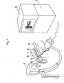
- FIG. 1 shows schematically the apparatus used for locking nailing, which consists of the x-ray source 3, the x-ray receiver 2 matched thereto and an image converter 4 with a monitor 5 connected to it.
- Located in the radiation field 9 of the X-ray apparatus is the patient's thigh 7 with the locking nail 6 already inserted into the medullary cavity of the femur 8, as well as the drill 1 with a sighting instrument 10 used to penetrate the outer corticalis.
- the relative position of the drill tip to the locking nail 6 and the alignment of the sighting instrument to the radiation field 9 can be tracked at any time on the monitor 5 of the image converter 4 and corrected if necessary.
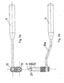
- the sighting instrument according to the invention shown in FIGS. 2a and b consists of a handle 11 to which a drill sleeve 12 is fastened, around which a crosshair sight 13 can be pivoted.
- the drill sleeve 12 essentially consists of a hollow cylinder having two teeth 21, which can receive a pin 16 made of plastic, at the tip of which a metal ball 17 is embedded.
- the actual visor 13 consists of two crosshairs which are rotated relative to one another in different planes or of two other suitable visor images, for example a circle and a point.
- the relative position of the intramedullary nail 6 with respect to the X-ray apparatus 2, 3 is aligned such that the locking holes 14, 15 are shown in a round manner on the monitor 5. This is the case when the axes of the locking holes 14, 15 are parallel to the radiation field 9.
- the hole to be locked should come to rest in the middle of the lower edge of the picture so that the crosshairs of the visor 13 come to rest in the center of the picture.
- the thigh 7 is then covered with a radiation protection mat which has an opening corresponding to the operating field.
- the sighting instrument 10 can be inserted through the skin incision with the pin 16 inserted (FIG. 3a).
- the pin 16 simplifies the insertion of the sighting instrument through the soft parts, thanks to its spherical tip. After insertion, the tip of the pin 16 with the spherical reference body 17 is placed over the center of the locking hole. This work step is shown in FIG. 3a and shows the reference body 17 lying exactly in the center of the drill sleeve 12.
- the visor 13 should not be considered at this time.
- the sighting instrument is pressed firmly onto the femur 8.
- the teeth 21 of the drill sleeve 12 prevent the sighting instrument 10 from slipping off the femur 8.
- the sighting instrument 10 is not rotated around the drill sleeve 12, since the drill sleeve 12 serving as tissue protection rests on the femur 8 with the two teeth and not with a central tip.
- the pin 16 is removed and a 4.5 mm drill sleeve is inserted into the drill sleeve 12.
- the 4.5mm drill is now inserted into this 4.5mm drill sleeve, the tip of which lies exactly above the center of the locking hole.
- the drilling direction is set under the image intensifier. This is done, as shown in Figure 3b, by aligning the visor 13 perpendicular to the radiation field 9.
- the first cortex can be drilled out with the 4.5mm drill.
- the drilling direction can be checked continuously with the image intensifier and corrected if necessary by adjusting the sighting image.
- the locking hole is covered by the drilling machine in this operation step.
- the 4.5mm drill is removed from the 4.5mm drill sleeve and a 3.2mm push-in sleeve is inserted down to the opposite cortex.
- the image intensifier can now be swiveled away and the counter cortex can be drilled out with the 3.2 mm drill.
- the screw length is measured, a thread is cut in the counter cortex and the locking screw is inserted.
- radiation sources 3 are other than mentioned in the application example X-ray apparatus ver - reversible, such as ultrasound or specifically for Training company also ordinary, visible light.
- the tool 1 guided with the aiming device according to the invention can, in addition to the drill mentioned in the example, also consist of a saw, syringe or other surgical instrument.
- the aiming device according to the invention is preferably suitable for surgical tools and instruments used in orthopedics, arthroscopy, spinal surgery and puncture, the method used here can also be used for other non-surgical purposes.
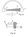
- the axis 18 of the drill sleeve 12 lying in a common plane enclose an angle with the optical sighting line 20 in order to take into account the divergence of the radiation field 9 (FIG. 4a) .
- This embodiment which increases precision can be implemented either in a fixed or adjustable manner.
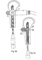
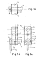
- FIGS. 5 a to c show the structure of this embodiment, which further simplifies the setting of the second locking screw, from three sides.
- the distance between the centers of the drill sleeve 23 and the drill sleeve 12 corresponds the exact distance between the centers of the two transverse bores 14, 15 of the locking nail 6.
- the visor 13 is arranged between the drill sleeve 23 and the drill sleeve 12 and is otherwise constructed in the same way as in the previously described embodiment of the invention.
- the block 22 in the radiation field 9 of the X-ray apparatus is made of a radiation-transmissive material, for example a plastic, and has two radiation-impermeable metal wires 24 running parallel to the plane of FIG. 5a.
- FIG. 6 shows the sighting instrument 10 after the first locking screw has been set in accordance with the surgical technique already described above.
- the associated monitor image typically shows an arrangement as shown in Figure 7a, i.e. the metal wires 24 embedded in the block 22 are not yet aligned parallel to the locking nail 6, but form an angle with it. Accordingly, the images of the drill sleeve 23 and the second locking hole 14 are not one above the other.
- the block 22, which is made of plastic, is essentially radiolucent, but in practice its contours can be recognized very weakly on the monitor image.
- Both the alignment and the fixing of the block 22 can be carried out by means of an ordinary hexagon screwdriver 28 which is inserted into the hexagon engagement of the locking screw 25, as shown in FIG. 6.
- both the drill sleeve 23 and the second Ver locking hole 14 is not circular, but is shown elliptically on the monitor. However, this does not matter for the alignment of the block 22, since only the parallelism of the reference metal wires 24 with the locking nail 6 is to be considered.
- a tissue protection sleeve is first inserted through the drill sleeve 23, into which the 4.5 mm drill sleeve can then be inserted.
- the rest of the procedure corresponds to that of setting the first locking screw.
- This time-saving and precision-increasing embodiment of the invention enables the already reduced x-ray dose to be reduced again to about half.
Abstract
Description
Die Erfindung bezieht sich auf ein Visierinstrument, insbesondere für chirurgische Zwecke, mit einem Handgriff und einer damit verbundenen Bohrhülse, dessen Verwendung, sowie auf ein Verfahren zur kontrollierten Durchdringung eines Materials in einer gewünschten Richtung mittels eines Werkzeugs.The invention relates to a sighting instrument, in particular for surgical purposes, with a handle and a drill sleeve connected to it, its use, and to a method for the controlled penetration of a material in a desired direction by means of a tool.
Es sind bereits Vorrichtungen bekannt, bei denen eine Bohrlehre mittels eines Röntgenbildwandlers justiert und anschliessend in der gewünschten Position fixiert wird. Beispielsweise ist aus der CH-A5 635 998 ein distales Zielgerät für die Verriegelungsnagelung bekannt geworden, mit einem Zielkopf, der eine Bohrung zur Aufnahme einer Zielhülse aufweist. Die Zielkopfhalterung ist in einer Fassung angebracht, die mit dem Röntgengerät verbunden ist und von diesem abhängig ist. Wegen der dadurch bewirkten schwerfälligen Positionierung und Fixierung ist die Zielgenauigkeit unbefriedigend. Durch die fixe Anordnung ergibt sich zudem eine eingeschränkte Betriebsweise.Devices are already known in which a drilling jig is adjusted by means of an X-ray image converter and then fixed in the desired position. For example, a distal target device for locking nailing has become known from CH-A5 635 998, with a target head which has a bore for receiving a target sleeve. The target head holder is attached in a socket that is connected to the X-ray device and depends on it. Because of the cumbersome positioning and fixation this causes, the accuracy of the aim is unsatisfactory. The fixed arrangement also results in a restricted operating mode.
Es ist daher auch bekanntgeworden, ein distales Zielgerät zu schaffen, das unabhängig vom Röntgengerät verwendet werden kann, beispielsweise aus dem DE-U1 84 17 428, mit einem in einer Halterung liegenden, röntgenstrahlendurchlässigen Aufnahmekopf zur Aufnahme eines Bohrers oder eines Bohrdrahtes. Auch bei dieser verbesserten Vorrichtung verbleiben aber gewichtige Nachteile, insbesondere die Tatsache, dass der Zielvorgang in der Querbohrung des Verriegelungsnagels stattfindet, was eine starke Abdunkelung des Arbeitsfeldes und eine niedrige Bildauflösung bewirkt.It has therefore also become known to create a distal target device which can be used independently of the X-ray device, for example from DE-U1 84 17 428, with a receiving head lying in a holder and permeable to X-rays for receiving a drill or a drill wire. This improved device also has major disadvantages, in particular the fact that the aiming process takes place in the transverse bore of the locking nail, which results in a strong darkening of the working area and a low image resolution.
Schliesslich führt das Fehlen einer das Gewebe schützenden Bonrhälse zu einer Schädigung der Weichteile bei jedem Auswechseln des zu verwendenden Werkzeuges oder Instrumentes.Finally, the lack of a bone neck protecting the tissue causes damage to the soft tissues each time the tool or instrument to be used is replaced.
Alle bekannten Vorrichtungen sind zudem mit dem schwerwiegenden Mangel behaftet, während der Operation keine Ueberprüfung des Zielvorganges und entsprechende Korrekturen zu ermöglichen.All known devices also suffer from the serious deficiency of not being able to check the target process and make corrections during the operation.
Hier will die Erfindung Abhilfe schaffen. Die Erfindung, wie sie in den Ansprüchen gekennzeichnet ist, löst die Aufgabe ein Visierinstrument der beschriebenen Art zu schaffen mit welchem auch während der Werkzeugbetätigung eine permanente Kontrolle und Korrektur der relativen Lage der Achse der Bohrhülse bezüglich einer gewünschten Richtung möglich ist und ein optimaler Gewebeschutz gewährleistet ist.The invention seeks to remedy this. The invention, as characterized in the claims, solves the problem of creating a sighting instrument of the type described, with which a permanent control and correction of the relative position of the axis of the drill sleeve with respect to a desired direction is possible even during tool operation and ensures optimal tissue protection is.
Die durch die Erfindung erreichten Vorteile sind im wesentlichen darin zu sehen, dass mittels eines einfachen, platzsparenden Visierinstruments höchste Präzision bei der Anwendung von Werkzeugen, insbesondere chirurgischer Art, erzielt werden kann und dass insgesamt der Zielvorgang wesentlich verkürzt werden kann, was beim Arbeiten in einem Röntgenstrahlfeld auch von der Arbeitssicherheit her bedeutsam ist. So konnte beispielsweise die Röntgenbestrahlung bei ei- ner typischen Verriegelung der Marknagelung von mehreren Minuten auf etwa 10 Sekunden reduziert werden.The advantages achieved by the invention are essentially to be seen in the fact that by means of a simple, space-saving sighting instrument the highest precision can be achieved when using tools, in particular of a surgical type, and that overall the aiming process can be significantly shortened, which is when working in one X-ray field is also important in terms of occupational safety. For example, the X - ray radiation could be reduced from several minutes to about 10 seconds with a typical locking of the intramedullary nail.
Durch Verlagerung des Visiervorgangs ausserhalb der Querbohrung des Verriegelungsnagels konnte zudem eine erheblich verbesserte Bildauflösung erreicht werden.By shifting the sighting process outside the cross hole of the locking nail, a significantly improved image resolution could also be achieved.
Im folgenden wird die Erfindung anhand einer lediglich einen Anwendungsfall darstellenden Zeichnung näher erläutert.The invention is explained in more detail below with reference to a drawing which represents only one application.
Es zeigt
- Figur 1 in perspektivischer Darstellung das Operationsfeld bei einer Verriegelungsnagelung mit dem erfindungsgemässen Visierinstrument und der für den Visiervorgang benötigten Röntgenapparatur;
- Figur 2a eine Aufsicht des erfindungsgemässen Visierinstruments;
- Figur 2b eine Seitenansicht des erfindungsgemässen Visierintrumentes mit einem in die Bohrhülse eingeführten Stift zur Setzung des Positionspunktes;
- Figur 3a eine perspektivische Ansicht der erfindungsgemässen Instrumentenkonfiguration gemäss Figur 2b im positionierten aber noch nicht ausgerichteten Zustand;
- Figur 3b eine perspektivische Ansicht des erfindungsgemässen Visierinstrumentes im positionierten und im Strahlenfeld ausgerichteten Zustand mit dem in die Bohrhülse eingeführten Bohrer;
- Figur 4a eine schematische Darstellung des Strahlenfeldes einer Röntgenapparatur;
- Figur 4b einen Schnitt durch die Bohrhülse und das Visier des erfindungsgemässen Visierinstrumentes;
- Figur 5a eine Aufsicht des erfindungsgemässen Visierinstrumentes mit einer zusätzlichen Bohrbüchse für das Setzen der zweiten Verriegelungsschraube;
- Figur 5b eine Seitenansicht von links der Figur 5a;
- Figur 5c eine Seitenansicht von oben der Figur 5a;
Figur 6 eine perspektivische Ansicht des Visierinstrumentes gemäss Fig. 5 mit eingesetzter erster Verriegelungsschraube;- Figur 7a ein Monitorbild des nicht ausgerichteten Visierinstrumentes gemäss
Figur 6; und - Figur 7b ein Monitorbild des ausgerichteten Visierinstru- mentes gemäss
Figur 6.
- FIG. 1 shows a perspective illustration of the operating field in the case of locking nailing with the sighting instrument according to the invention and the X-ray apparatus required for the sighting process;
- FIG. 2a shows a top view of the sighting instrument according to the invention;
- FIG. 2b shows a side view of the sighting instrument according to the invention with a pin inserted into the drill sleeve for setting the position point;
- FIG. 3a shows a perspective view of the instrument configuration according to the invention according to FIG. 2b in the positioned but not yet aligned state;
- FIG. 3b shows a perspective view of the sighting instrument according to the invention in the positioned and aligned state in the radiation field with the drill inserted into the drill sleeve;
- Figure 4a is a schematic representation of the radiation field of an X-ray apparatus;
- FIG. 4b shows a section through the drill sleeve and the sight of the sighting instrument according to the invention;
- FIG. 5a shows a top view of the sighting instrument according to the invention with an additional drill sleeve for setting the second locking screw;
- Figure 5b is a left side view of Figure 5a;
- Figure 5c is a side view from above of Figure 5a;
- FIG. 6 shows a perspective view of the sighting instrument according to FIG. 5 with the first locking screw inserted;
- 7a shows a monitor image of the non-aligned sighting instrument according to FIG. 6; and
- 7b shows a screen image of the aligned Visierinstru - mentes according to FIG. 6
In Figur 1 ist schematisch die bei einer Verriegelungsnagelung verwendete Apparatur dargestellt, welche aus der Röntgenquelle 3, dem darauf abgestimmten Röntgenstrahlenempfänger 2 und einen an diesen angeschlossenen Bildwandler 4 mit Monitor 5 besteht.FIG. 1 shows schematically the apparatus used for locking nailing, which consists of the
Im Strahlenfeld 9 der Röntgenapparatur befindet sich der Oberschenkel 7 des Patienten mit dem bereits in die Markhöhle des Femur 8 eingeführten Verriegelungsnagel 6, sowie der zur Durchbohrung der äusseren Corticalis angesetzte Bohrer 1 mit Visierinstrument 10.Located in the
Die relative Lage der Bohrerspitze zum Verriegelungsnagel 6 sowie die Ausrichtung des Visierinstruments zum Strahlenfeld 9 kann jederzeit auf dem Monitor 5 des Bildwandlers 4 verfolgt und nötigenfalls korrigiert werden.The relative position of the drill tip to the
Das in Figur 2a und b dargestellte erfindungsgemässe Visierinstrument besteht aus einem Handgriff 11 an dem eine Bohrhülse 12 befestigt ist um die ein Fadenkreuzvisier 13 verschwenkt werden kann.The sighting instrument according to the invention shown in FIGS. 2a and b consists of a
Die Bohrhülse 12 besteht im wesentlichen aus einem zwei Zähne 21 aufweisenden Hohlzylinder, der einen Stift 16 aus Kunststoff aufnehmen kann, an dessen Spitze eine Metallkugel 17 eingebettet ist. Das eigentliche Visier 13 besteht aus zwei in verschiedenen Ebenen liegenden gegeneinander verdrehten Fadenkreuzen oder aus zwei anderen geeigneten Visierbil- dern,beispielsweise einen Kreis und einen Punkt.The
Nun soll anhand der Figuren 1, 3a und 3b die Operationstechnik bei der Verriegelung der Marknagelung mit dem erfindungsgemässen Visierinstrument 10 beschrieben werden.The surgical technique for locking the intramedullary nailing with the
Bevor das erfindungsgemässe Visierinstrument 10 bei der distalen Verriegelung des Marknagels 6 zur Anwendung kommt wird die relative Lage des Marknagels 6 zur Röntgenapparatur 2,3 derart ausgerichtet, dass die Verriegelungslöcher 14,15 auf dem Monitor 5 rund abgebildet werden. Dies ist dann der Fall, wenn die Achsen der Verriegelungslöcher 14,15 parallel zum Strahlenfeld 9 liegen. Das zu verriegelnde Loch sollte dabei in der Mitte des unteren Bildrandes zu liegen kommen, damit das Fadenkreuz des Visiers 13 in die Bildmitte zu stehen kommt. Hierauf wird der Oberschenkel 7 mit einer Strahlenschutzmatte bedeckt, welche eine dem Operationsfeld entsprechende Oeffnung besitzt.Before the
Nachdem unter Bildverstärker-Kontrolle ein genau über dem Verriegelungsloch liegender Hautschnitt bis auf die Knochenoberfläche geführt-worden ist kann das Visierinstrument 10, mit eingeschobenem Stift 16, durch den Hautschnitt eingeführt werden (Fig.3a).After a skin incision lying exactly above the locking hole has been made up to the bone surface under image intensifier control, the
Der Stift 16 vereinfacht das Einführen des Visierinstrumentes durch die Weichteile, dank seiner kugelförmigen Spitze. Nach erfolgter Einführung wird die Spitze des Stiftes 16 mit dem kugelförmigen Referenzkörper 17 über das Zentrum des Verriegelungsloches gesetzt. Dieser Arbeitsschritt ist in Figur 3a dargestellt und zeigt den exakt im Zentrum der Bohrhülse 12 liegenden Referenzkörper 17.The
Das Visier 13 soll in diesem Zeitpunkt noch nicht beachtet werden. Wenn der Referenzkörper 17 genau im Zentrum des Verriegelungsloches liegt wird das Visierinstrument fest auf den Femur 8 gedrückt. Die Zähne 21 der Bohrhülse 12 verhindern ein Abrutschen des Visierinstrumentes 10 vom Femur 8.The
In diesem Stadium der Operation ist darauf zu achten, dass das Visierinstrument 10 nicht um die Bohrhülse 12 gedreht wird, da die als Gewebeschutz dienende Bohrhülse 12 mit den beiden Zähnen und nicht mit einer zentrischen Spitze auf dem Femur 8 aufliegt.At this stage of the operation, care must be taken that the
Nach erfogter Positionierung des Visierinstrumentes 10 wird der Stift 16 entfernt und eine 4,5mm Bohrbüchse in die Bohrhülse 12 eingesetzt. In diese 4,5mm Bohrbüchse wird nun der 4,5mm Bohrer eingeführt, dessen Spitze exakt über dem Zentrum des Verriegelungsloches zu liegen kommt. Nun wird die Bohrrichtung unter dem Bildverstärker eingestellt. Dies geschieht, wie in Figur 3b dargestellt, indem das Visier 13 senkrecht zum Strahlenfeld 9 ausgerichtet wird. Jetzt kann die erste Kortikalis mit dem 4,5mm Bohrer aufgebohrt werden. Die Bohrrichtung kann laufend mit dem Bildverstärker überprüft werden und nötigenfalls durch Anpassung des Visierbildes korrigiert werden.After the positioning of the
Wie in Figur 3b ersichtlich ist das Verriegelungsloch bei diesem Operationsschritt durch die Bohrmaschine verdeckt. Nach Durchbohrung der ersten Kortikalis wird der 4,5mm Bohrer aus der 4,5mm Bohrbüchse entfernt und eine 3,2mm Steckbohrbüchse bis auf die Gegenkortikalis eingeführt. Der Bildverstärker kann nun weggeschwenkt werden und die Gegenkortikalis mit dem 3,2mm Bohrer aufgebohrt werden. Nach Entfernung der 3,2mm Steckbohrbüchse wird die Schraubenlänge gemessen, ein Gewinde in die Gegenkortikalis geschnitten und die Verriegelungsschraube gesetzt.As can be seen in FIG. 3b, the locking hole is covered by the drilling machine in this operation step. After drilling through the first cortex, the 4.5mm drill is removed from the 4.5mm drill sleeve and a 3.2mm push-in sleeve is inserted down to the opposite cortex. The image intensifier can now be swiveled away and the counter cortex can be drilled out with the 3.2 mm drill. After removing the 3.2mm push-in sleeve, the screw length is measured, a thread is cut in the counter cortex and the locking screw is inserted.
Für das Setzen der zweiten Verriegelungsschraube wird die ganze beschriebene Prozedur grundsätzlich wiederholt.The entire procedure described is basically repeated for setting the second locking screw.
Je nach Anwendungsfall sind ausser der im Anwendungsbeispiel erwähnten Röntgenapparatur auch andere Strahlenquellen 3 ver- wendbar, beispielsweise Ultraschall oder speziell für den Ausbildungsbetrieb auch gewöhnliches, sichtbares Licht.Depending on the application,
Das mit der erfindungsgemässen Zielvorrichtung geführte Werkzeug 1 kann ausser dem im Beispiel erwähnten Bohrer auch aus einer Säge, Spritze oder einem anderen chirurgischen Instrument bestehen.The tool 1 guided with the aiming device according to the invention can, in addition to the drill mentioned in the example, also consist of a saw, syringe or other surgical instrument.
obwohl sich die erfindungsgemässe Zielvorrichtung vorzugsweise für in der Orthopädie, Arthroskopie, Wirbelsäulenchirurgie und Punktion verwendete chirurgische Werkzeuge und Instrumente eignet, kann das dabei angewendete Verfahren auch für andere nichtchirurgische Zwecke verwendet werden. Um die Präzision des Visierinstrumentes 10 weiter zu erhöhen kann, wie in Figur 4b dargestellt,die in einer gemeinsamen Ebene liegende Achse 18 der Bohrhülse 12 mit der optischen Visierlinie 20 einen Winkel einschliessen um der Divergenz des Strahlenfeldes 9 (Fig.4a) Rechnung zu tragen. Diese präzionserhöhende Ausführungsform kann entweder fix oder justierbar realisiert werden.Although the aiming device according to the invention is preferably suitable for surgical tools and instruments used in orthopedics, arthroscopy, spinal surgery and puncture, the method used here can also be used for other non-surgical purposes. In order to further increase the precision of the
Eine weitere verbesserte Ausführungsform des erfindungsgemässen Visierinstrumentes 10 ist in den Figuren 5 und 6 dargestellt. Die Figuren 5 a bis c zeigen von drei Seiten den Aufbau dieser das Setzen der zweiten Verriegelungsschraube weiter vereinfachenden Ausführungsform. Der mittels der Drehgelenkverbindung 26 schwenkbar um die Bohrhülse 12 angeordnete und mittels der Feststellschraube 25 fixierbare, quaderförmige Block 22 trägt neben dem Visier 13 eine für das Setzen der zweiten Verriegelungsschraube bestimmte Bohrbüchse 23. Der Abstand zwischen den Zentren der Bohrbüchse 23 und der Bohrhülse 12 entspricht dabei genau dem Abstand der Zentren der beiden Querbohrungen 14, 15 des Verriegelungsnagels 6.A further improved embodiment of the
Das Visier 13 ist zwischen der Bohrbüchse 23 und der Bohrhülse 12 angeordnet und im übrigen gleich aufgebaut wie in der bereits beschriebenen Ausführungsform der Erfindung.The
Um den Block 22 im Strahlenfeld 9 der Röntgenapparatur parallel ausrichten zu können ist dieser aus einem strahlendurchlässigen Material, beispielsweise einem Kunststoff gefertigt und weist zwei zur Zeichenebene der Figur 5a parallel verlaufende, strahlenundurchlässige Metalldrähte 24 auf.In order to be able to align the
Der technische Ablauf des Setzens der zweiten Verriegelungsschraube mit Hilfe dieser verbesserten Ausführungsform der Erfindung ist aus den Figuren 6 und 7 ersichtlich.The technical sequence of setting the second locking screw with the aid of this improved embodiment of the invention can be seen from FIGS. 6 and 7.
Figur 6 zeigt das Visierinstrument 10 nach erfolgtem Setzen der ersten Verriegelungsschraube gemäss der bereits oben beschriebenen Operationstechnik. Das dazugehörende Monitorbild zeigt typischerweise eine Anordnung wie in Figur 7a dargestellt, d.h. die im Block 22 eingelassenen Metalldrähte 24 sind noch nicht parallel zum Verriegelungsnagel 6 ausgerichtet, sondern schliessen einen Winkel mit diesem ein. Entsprechend liegen die Abbildungen der Bohrbüchse 23 und des zweiten Verriegelungsloches 14 nicht übereinander. Der aus Kunststoff bestehende Block 22 ist zwar im wesentlichen strahlendurchlässig, doch lassen sich in der Praxis seine Konturen ganz schwach auf dem Monitorbild erkennen.FIG. 6 shows the
Der Chirurg brauchtnun lediglich den Block 22 so lange um die starr mit dem Knochen 8 verbundene Bohrhülse 12 zu drehen, bis er im Monitorbild die Referenz-Metalldrähte 24 parallel zum Verriegelungsnagel 6 ausgerichtet hat und den Block 22 in dieser Position mittels der Feststellschraube 25 zu fixieren.The surgeon now only needs to rotate the
Sowohl das Ausrichten, als auch das Fixieren des Blockes 22 kann mittels eines gewöhnlichen Sechskantschraubenziehers 28 erfolgen, der in den Sechskanteingriff der Feststellschraube 25 eingeführt wird, wie dies in Figur 6 dargestellt ist.Both the alignment and the fixing of the
Bedingt durch die Divergenz des Strahlenfeldes 9 (Fig. 4a) werden sowohl die Bohrbüchse 23, als auch das zweite Verriegelungsloch 14 nicht kreisförmig, sondern elliptisch auf dem Monitor abgebildet. Für das Ausrichten des Blockes 22 spielt dies jedoch keine Rolle, da einzig der Parallelität der Referenzmetalldrähte 24 mit dem Verriegelungsnagel 6 Beachtung zu schenken ist.Due to the divergence of the radiation field 9 (Fig. 4a), both the
Nach Fixierung des Blockes 22 mittels der Feststellschraube 25 kann der Chirurg den Handgriff 11 des Visierinstruments 10 loslassen, so dass er beide Hände frei hat um die zweite Verriegelungsschraube zu setzen. Dazu wird zuerst eine in der Zeichnung nicht dargestellte Gewebeschutzhülse durch die Bohrbüchse 23 gesteckt, in welche dann die 4,5 mm Bohrbüchse eingeführt werden kann.After fixation of the
Der weitere Ablauf entspricht demjenigen des Setzens der ersten Verriegelungsschraube.The rest of the procedure corresponds to that of setting the first locking screw.
Durch diese zeitsparende und präzisionserhöhende Ausführungsform der Erfindung gelingt es die bereits reduzierte Röntgendosis nochmals auf etwa die Hälfte zu senken.This time-saving and precision-increasing embodiment of the invention enables the already reduced x-ray dose to be reduced again to about half.
Claims (13)
Applications Claiming Priority (4)
| Application Number | Priority Date | Filing Date | Title |
|---|---|---|---|
| CH1932/85 | 1985-05-07 | ||
| CH1932/85A CH664725A5 (en) | 1985-05-07 | 1985-05-07 | Eyepiece instrument for surgical alignment |
| CH4280/85 | 1985-10-03 | ||
| CH4280/85A CH671873A5 (en) | 1985-10-03 | 1985-10-03 |
Publications (2)
| Publication Number | Publication Date |
|---|---|
| EP0201737A2 true EP0201737A2 (en) | 1986-11-20 |
| EP0201737A3 EP0201737A3 (en) | 1988-11-17 |
Family
ID=25689033
Family Applications (1)
| Application Number | Title | Priority Date | Filing Date |
|---|---|---|---|
| EP86105110A Withdrawn EP0201737A3 (en) | 1985-05-07 | 1986-04-14 | Sighting instrument |
Country Status (2)
| Country | Link |
|---|---|
| EP (1) | EP0201737A3 (en) |
| BR (1) | BR8601918A (en) |
Cited By (7)
| Publication number | Priority date | Publication date | Assignee | Title |
|---|---|---|---|---|
| EP0281763A2 (en) * | 1987-03-07 | 1988-09-14 | Howmedica GmbH | Accessory instrument for positioning implantation holes of attachment nails |
| FR2634641A1 (en) * | 1988-07-28 | 1990-02-02 | Michel Jean Pierre | DEVICE FOR THE POSITIONING OF AT LEAST ONE FIXING MEMBER THROUGH AN IMPLANT, OF THE CENTRO-MEDULINAL NAIL TYPE |
| EP0354395A2 (en) * | 1988-08-10 | 1990-02-14 | Ace Medical Company | Intramedullary rod targetting device |
| US4917111A (en) * | 1987-10-15 | 1990-04-17 | Dietmar Pennig | Instrument for aiming and hole forming for implantation of locking nails of the like |
| FR2645428A1 (en) * | 1989-04-11 | 1990-10-12 | Hardy Jean Marie | FIXER FOR ORTHOPEDIC INTERVENTION |
| WO1991003982A1 (en) * | 1989-09-13 | 1991-04-04 | Isis Innovation Limited | Apparatus and method for aligning drilling apparatus in surgical procedures |
| EP0518071A1 (en) * | 1991-06-13 | 1992-12-16 | Howmedica GmbH | Device for making holes for the implantation of interlocking nails |
Citations (5)
| Publication number | Priority date | Publication date | Assignee | Title |
|---|---|---|---|---|
| US3704707A (en) * | 1971-04-06 | 1972-12-05 | William X Halloran | Orthopedic drill guide apparatus |
| FR2417970A1 (en) * | 1978-02-22 | 1979-09-21 | Howmedica | DISTAL SIGHTING DEVICE FOR LOCKING NAIL MOUNTING |
| SU848015A1 (en) * | 1978-10-02 | 1981-07-23 | Казанский Ордена Трудового Красногознамени Государственный Медицинскийинститут Им. C.B.Курашова | Device for aimed puncture |
| DE3205404A1 (en) * | 1982-02-16 | 1983-09-15 | Patrick Dr.med. 3590 Bad Wildungen Kluger | Device for checking the directionally accurate guidance of a surgical tool |
| DE8417428U1 (en) * | 1984-06-08 | 1984-09-13 | Howmedica International, Inc. Zweigniederlassung Kiel, 2300 Kiel | Target device |
-
1986
- 1986-04-14 EP EP86105110A patent/EP0201737A3/en not_active Withdrawn
- 1986-04-29 BR BR8601918A patent/BR8601918A/en unknown
Patent Citations (5)
| Publication number | Priority date | Publication date | Assignee | Title |
|---|---|---|---|---|
| US3704707A (en) * | 1971-04-06 | 1972-12-05 | William X Halloran | Orthopedic drill guide apparatus |
| FR2417970A1 (en) * | 1978-02-22 | 1979-09-21 | Howmedica | DISTAL SIGHTING DEVICE FOR LOCKING NAIL MOUNTING |
| SU848015A1 (en) * | 1978-10-02 | 1981-07-23 | Казанский Ордена Трудового Красногознамени Государственный Медицинскийинститут Им. C.B.Курашова | Device for aimed puncture |
| DE3205404A1 (en) * | 1982-02-16 | 1983-09-15 | Patrick Dr.med. 3590 Bad Wildungen Kluger | Device for checking the directionally accurate guidance of a surgical tool |
| DE8417428U1 (en) * | 1984-06-08 | 1984-09-13 | Howmedica International, Inc. Zweigniederlassung Kiel, 2300 Kiel | Target device |
Cited By (12)
| Publication number | Priority date | Publication date | Assignee | Title |
|---|---|---|---|---|
| EP0281763A2 (en) * | 1987-03-07 | 1988-09-14 | Howmedica GmbH | Accessory instrument for positioning implantation holes of attachment nails |
| EP0281763A3 (en) * | 1987-03-07 | 1989-08-09 | Howmedica Gmbh | Accessory instrument for positioning implantation holes of attachment nails |
| US4917111A (en) * | 1987-10-15 | 1990-04-17 | Dietmar Pennig | Instrument for aiming and hole forming for implantation of locking nails of the like |
| FR2634641A1 (en) * | 1988-07-28 | 1990-02-02 | Michel Jean Pierre | DEVICE FOR THE POSITIONING OF AT LEAST ONE FIXING MEMBER THROUGH AN IMPLANT, OF THE CENTRO-MEDULINAL NAIL TYPE |
| EP0358579A2 (en) * | 1988-07-28 | 1990-03-14 | ICP FRANCE, Société Anonyme | Aiming device for positioning of at least one fixation element through an implant in form of an intramedullary nail |
| EP0358579A3 (en) * | 1988-07-28 | 1990-07-18 | ICP FRANCE, Société Anonyme | Aiming device for positioning of at least one fixation element through an implant in form of an intramedullary nail |
| EP0354395A2 (en) * | 1988-08-10 | 1990-02-14 | Ace Medical Company | Intramedullary rod targetting device |
| EP0354395A3 (en) * | 1988-08-10 | 1990-12-05 | Ace Medical Company | Intramedullary rod targetting device |
| FR2645428A1 (en) * | 1989-04-11 | 1990-10-12 | Hardy Jean Marie | FIXER FOR ORTHOPEDIC INTERVENTION |
| WO1990011727A1 (en) * | 1989-04-11 | 1990-10-18 | Hardy Jean Marie | Fixing device for orthopedic use |
| WO1991003982A1 (en) * | 1989-09-13 | 1991-04-04 | Isis Innovation Limited | Apparatus and method for aligning drilling apparatus in surgical procedures |
| EP0518071A1 (en) * | 1991-06-13 | 1992-12-16 | Howmedica GmbH | Device for making holes for the implantation of interlocking nails |
Also Published As
| Publication number | Publication date |
|---|---|
| EP0201737A3 (en) | 1988-11-17 |
| BR8601918A (en) | 1986-12-30 |
Similar Documents
| Publication | Publication Date | Title |
|---|---|---|
| CH671873A5 (en) | ||
| DE69837781T2 (en) | Target device for implant devices | |
| DE69912600T2 (en) | Pen for temporary attachment of a bone plate | |
| DE4412604C2 (en) | Device for the ventral screwing of dens fractures with compression screws | |
| DE19713416B4 (en) | Guide device for an intervertebral implant | |
| DE60212852T2 (en) | TIBIAL RESEARCH MANAGEMENT | |
| EP0514662B1 (en) | Surgery device to position osteosynthesis fixation elements, particularly bone screws | |
| DE60101162T2 (en) | X-RAY TRANSFERABLE GUIDE QUIDE | |
| DE69531803T2 (en) | Guide system for milling bones | |
| DE102004058725B4 (en) | Surgical navigation tracking device adapter | |
| DE69630884T2 (en) | GUIDE TO CUT | |
| EP0135804A2 (en) | Device to locate through-holes in intramedullary implants | |
| DE3925488A1 (en) | MILLING ALIGNMENT GUIDE FOR OSTEOPLASTIC SURGERY | |
| DE202005015975U1 (en) | target device | |
| DE3842645A1 (en) | SAFE GAUGE SYSTEM | |
| DE10301444A1 (en) | Intramedullary nail, device for inserting a screw therein, and associated procedure | |
| EP0322363A1 (en) | Positioning device for total condylar knee prostheses | |
| EP1354562B1 (en) | Improved bone fixation | |
| CH668692A5 (en) | Bone pin alignment instrument - has lockable head pivoting in all directions | |
| DE2919935A1 (en) | DEVICE FOR GUIDING SURGICAL INSTRUMENTS IN CONVERSION OSTOTOMY ON HUMAN BONE | |
| EP0201737A2 (en) | Sighting instrument | |
| EP1455662B1 (en) | Targeting device for a fracture pin | |
| DE102014113658A1 (en) | Device for repositioning bone fracture fragments | |
| DE10335388A1 (en) | Surgical reference device, comprising bone plate attached to femur for safe joining of rigid body | |
| DE3245680C2 (en) | Distal aiming device for an interlocking nail |
Legal Events
| Date | Code | Title | Description |
|---|---|---|---|
| PUAI | Public reference made under article 153(3) epc to a published international application that has entered the european phase |
Free format text: ORIGINAL CODE: 0009012 |
|
| AK | Designated contracting states |
Kind code of ref document: A2 Designated state(s): AT BE CH DE FR GB LI LU NL SE |
|
| RIN1 | Information on inventor provided before grant (corrected) |
Inventor name: FRIGG, ROBERT Inventor name: GYSIN, PAUL Inventor name: RITTER, GEBHARD Inventor name: PERREN, STEPHEN M., PROF. DR. MED. Inventor name: JENNY, URS |
|
| PUAL | Search report despatched |
Free format text: ORIGINAL CODE: 0009013 |
|
| AK | Designated contracting states |
Kind code of ref document: A3 Designated state(s): AT BE CH DE FR GB LI LU NL SE |
|
| 17P | Request for examination filed |
Effective date: 19881128 |
|
| 17Q | First examination report despatched |
Effective date: 19910820 |
|
| STAA | Information on the status of an ep patent application or granted ep patent |
Free format text: STATUS: THE APPLICATION IS DEEMED TO BE WITHDRAWN |
|
| 18D | Application deemed to be withdrawn |
Effective date: 19920922 |
|
| RIN1 | Information on inventor provided before grant (corrected) |
Inventor name: PERREN, STEPHEN M., PROF. DR. MED. Inventor name: RITTER, GEBHARD Inventor name: FRIGG, ROBERT Inventor name: JENNY, URS Inventor name: GYSIN, PAUL |