EP0201271A2 - Improvements in, or relating to, the electrical stimulation of muscle - Google Patents
Improvements in, or relating to, the electrical stimulation of muscle Download PDFInfo
- Publication number
- EP0201271A2 EP0201271A2 EP86303262A EP86303262A EP0201271A2 EP 0201271 A2 EP0201271 A2 EP 0201271A2 EP 86303262 A EP86303262 A EP 86303262A EP 86303262 A EP86303262 A EP 86303262A EP 0201271 A2 EP0201271 A2 EP 0201271A2
- Authority
- EP
- European Patent Office
- Prior art keywords
- stimulator
- muscle
- system controller
- data
- pulses
- Prior art date
- Legal status (The legal status is an assumption and is not a legal conclusion. Google has not performed a legal analysis and makes no representation as to the accuracy of the status listed.)
- Granted
Links
Images


Classifications
-
- A—HUMAN NECESSITIES
- A61—MEDICAL OR VETERINARY SCIENCE; HYGIENE
- A61N—ELECTROTHERAPY; MAGNETOTHERAPY; RADIATION THERAPY; ULTRASOUND THERAPY
- A61N1/00—Electrotherapy; Circuits therefor
- A61N1/18—Applying electric currents by contact electrodes
- A61N1/32—Applying electric currents by contact electrodes alternating or intermittent currents
- A61N1/36—Applying electric currents by contact electrodes alternating or intermittent currents for stimulation
- A61N1/36003—Applying electric currents by contact electrodes alternating or intermittent currents for stimulation of motor muscles, e.g. for walking assistance
-
- A—HUMAN NECESSITIES
- A61—MEDICAL OR VETERINARY SCIENCE; HYGIENE
- A61N—ELECTROTHERAPY; MAGNETOTHERAPY; RADIATION THERAPY; ULTRASOUND THERAPY
- A61N1/00—Electrotherapy; Circuits therefor
- A61N1/18—Applying electric currents by contact electrodes
- A61N1/32—Applying electric currents by contact electrodes alternating or intermittent currents
- A61N1/36—Applying electric currents by contact electrodes alternating or intermittent currents for stimulation
- A61N1/36014—External stimulators, e.g. with patch electrodes
- A61N1/3603—Control systems
- A61N1/36034—Control systems specified by the stimulation parameters
-
- A—HUMAN NECESSITIES
- A61—MEDICAL OR VETERINARY SCIENCE; HYGIENE
- A61N—ELECTROTHERAPY; MAGNETOTHERAPY; RADIATION THERAPY; ULTRASOUND THERAPY
- A61N1/00—Electrotherapy; Circuits therefor
- A61N1/18—Applying electric currents by contact electrodes
- A61N1/32—Applying electric currents by contact electrodes alternating or intermittent currents
- A61N1/36—Applying electric currents by contact electrodes alternating or intermittent currents for stimulation
- A61N1/372—Arrangements in connection with the implantation of stimulators
- A61N1/37211—Means for communicating with stimulators
- A61N1/37235—Aspects of the external programmer
Definitions
- Muscle stimulators are known which provide for the electrical stimulation of muscles by application of pulses to an electrode arrangement applied to the skin overlying the muscle.
- a certain amount of adjustment of the characteristics of the pulse train has been possible by the operator.
- the present invention is, in part, concerned with providing an arrangement whereby the characteristics of a pulse series may be adjusted.
- the stimulator apparatus may preferably be of a shape and size such as to be personally portable, preferably carried about the person e.g. pocketa- ble.
- a stimulator of approximately the same size and possibly shape as the personal cassette players which have recently come on to the market and, as with such players, the stimulator may be housed in a casing which is adapted, for example by the provision of a clip, belt loop, carrying strap or other attachment means to facilitate the stimulator being carried or wom about the person.
- the muscle stimulator section of the system controller will provide a reasonably comprehensive set of controls for enabling the pulse characteristics of a pulse train to be determined, i.e. pulse repetition rate, interval, length, amplitude and so forth.
- a number of parallel output channels with independent amplitude controls may be provided.
- the stimulation pulse data is transferred in the form of predetermined binary words, e.g. ASCII characters used to represent particular parameters, and parameters values, of a stimulation pulse series.
- predetermined binary words e.g. ASCII characters used to represent particular parameters, and parameters values
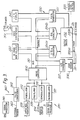
- Figures 1a, b and c show the three principal components of a system according to the present invention in three different operating configurations. These components are:-
- the characteristics of the stimulation pulses are controllable by its internal circuitry in accordance with a stored programme.
- This programme may be placed in the unit in any one of a number of ways, for example by having a replaceable memory module (such as 2B shown in Figure 2c) which fits into the unit but instead of or in addition to this, the unit preferably has a specially adapted interface arrangement whereby the desired pulse stimulation pattern(s) can be down-loaded to the unit from the system controller 1a.
- the programmable pulse generator is connected to the microcomputer 300 and memory 320 by means of the data bus 310. Also connected to the bus are an LCD display 340 and a voice synthesizer 350 which drives a loudspeaker 351.
- a manual level control 335 for the outputs to the electrodes and, a load sensing circuit 336 and analog to digital converter 337 which sense the loading on the electrodes connected to the output 33a and 333b and feed this information back in digital form to the microcomputer 300 via the data bus 310.
- the device may thus be arranged to be responsive to changes in the patient's skin resistance.
- this or other means e.g. separate electrodes applied to the skin
- the pulse generator 430 of the system controller is of similar structure to the pulse generator 330 of Figure 3 and is intended to operate in a similar manner. It has a pulse generator 431 which takes digital data from the data bus 410 and converts this to stimulating pulses which are distributed to the eight output channels by means of the output driving circuitry 432.
- the load sensor 436 is adapted to take information from each of the eight output channels rather than the two output channels of Figure 3.
- a course of treatment may comprise a mix of trophic stimulation and functional stimulation with more frequent use of trophic stimulation at the early stages of the treatment and or frequent use of functional stimulation towards the end.
- the start of treatment it may necessary for the start of treatment to consist wholly of trophic stimulation at the start.
- Both the personal unit 2 and the control unit 1 may be provided with a modem for exchanging data with one another or with a remote computer data base so as to enable stimulation pulse data and other useful data to be stored and or processed by the remote computer or exchanged between the personal unit 2 and the control 1 when it is not possible to bring them physically together.
- the personal unit 2 may have a microphone and loudspeaker arranged so that they can be held against the handset of a standard telephone, in which case as with conventional portable modems, these items may be surrounded by soundproofing material to shut out extraneous noise and, instead or as well, the personal units 2 and the control unit 1 may be provided with an internal modem directly connected to a standard telephone jack plug.
- the research unit 3 is adapted to be used in association with the system controller 1 to provide an 8 channel sophisticated computer driven neuromuscular stimulation controller for extensive research application; it may have inter alia RS232 and IEEE 488 interfaces for communication with the host computer which is to be used to control it, as well as a suitable e.g. parallel interface for communicating with the system controller 1.
- the instrument will be supplied with elaborate software control modules to run on its host computer and will be controlled by it over standard interfaces.
Abstract
Description
- The present invention relates to muscle stimulators and to the communication of stimulation data between a muscle stimulator and another device.
- Muscle stimulators are known which provide for the electrical stimulation of muscles by application of pulses to an electrode arrangement applied to the skin overlying the muscle. In the prior art, a certain amount of adjustment of the characteristics of the pulse train has been possible by the operator. The present invention is, in part, concerned with providing an arrangement whereby the characteristics of a pulse series may be adjusted.
- The present invention encompasses several different concepts which may be used either singly or in any desired combination with one another.
- According to the present invention there is provided a muscle stimulator system comprising a) at least one muscle stimulator apparatus, for the electrical stimulation of muscles by the application of electrical pulses to an electrode arrangement applied to the skin overlying the muscle, b) a system controller having means defining stimulating characteristics of electrical signals and means for transferring from the system controller to the or each stimulator apparatus data defining the characteristics of the electrical pulses, the stimulator apparatus being adapted to be operable remote from the system controller. The stimulator and remote device are preferably so adapted that data can be transferred between them without a direct electrical connection between them such as, for example, by means of an optical data link, an ultrasonic link, a radio link, etc. Data may instead or as well be transferred between them via a communication network, for example via a telephone network using modems or acoustic couplers.
- One of the reasons why it is desirable to provide for a transfer of data to enable the stimulation pulse characteristics to be changed is that although in the past the stimulation applied to the muscles has been essentially functional stimulation, i.e. simply causing a predetermined contract/relax cycle of the muscles, recently a new technique, known as "trophic" stimulation has been developed which, by suitable choice of the characteristics of the stimulation pulse series, can bring about a long term functional and/or structural change in the fibres of the muscle being stimulated. This is currently being developed with a view to providing therapeutic treatments for muscular disorders and dysfunctions and the particular trophic stimulation required for a particular muscle will vary. It is contemplated that the remote device will have access to a database of trophic code pulse series characteristics from which the appropriate data can be down loaded to the stimulator for application to the muscle in question. It is also contemplated that certain treatment regimes will require a combination of function and trophic stimulation with periods of trophic stimulation being interspersed with periods of functional stimulation. The data down loaded may thus comprise both functional and trophic stimulation data as well as data relating to how the two various patterns of stimulation are to be applied in sequence.
- The stimulator apparatus may preferably be of a shape and size such as to be personally portable, preferably carried about the person e.g. pocketa- ble. Thus one embodiment of this aspect of the present invention contemplates the provision of a stimulator of approximately the same size and possibly shape as the personal cassette players which have recently come on to the market and, as with such players, the stimulator may be housed in a casing which is adapted, for example by the provision of a clip, belt loop, carrying strap or other attachment means to facilitate the stimulator being carried or wom about the person.
- It will be appreciated from the above that the present invention allows "out patient" treatment of a patient at home, with the patient being provided with a personal muscle stimulator which is adapted so that it can be readily be carried around by him or her and which can be programmed by a trained operator from a clinic either by taking the stimulator to the clinic for reprogramming or by transmitting data to it e.g. over the telephone link.
- The personal stimulator, whose operation may be controlled by a suitably programmed microprocessor, can be arranged to record in a memory the history of use of the stimulator since the last updating of the pulse series data so that,. for example, this information can be transferred back to the remote device to give an indication of how much the stimulator has been used so that the appropriate next set of stimulation data to continue a particular course of treatment can be down-loaded.
- The muscle stimulator system controller may also include a muscle stimulator, as well as circuitry for enabling data defining a stimulation pulse series to be transferred to a remote muscle stimulator such as the personal stimulator mentioned above. This allows the system controller to be used as a stimulator in its own right and to control and manage stimulation provided by one or more remote stimulators. Thus one application of this controller which is currently contemplated is that a clinician would have the system controller for his or her use in treatment and/or research, with the facility being provided to down-load data to individual personal stimulators carried by patients or research subjects. The system controller may also have an interface to enable it to exchange data with a computer database held, for example, on a personal computer. Thus the clinician could built up or access a database of stimulation pulse data from which appropriate data could be selected for a particular treatment and then downloaded to a suitable personal muscle stimulator.
- For this purpose, it is contemplated that the muscle stimulator section of the system controller will provide a reasonably comprehensive set of controls for enabling the pulse characteristics of a pulse train to be determined, i.e. pulse repetition rate, interval, length, amplitude and so forth. A number of parallel output channels with independent amplitude controls may be provided.
- Preferably the system controller may be used in association with a muscle stimulation control device which is provided with circuitry which interacts with the circuitry of the system controller so as to place the functions and controls of the system controller under the control of a separate computer, e.g. a personal computer, so that the system controller can be operated by the keyboard (or other input device) of this computer.
- Conveniently the system controller may also be fitted with a printer by which the operator can generate for instance a summary of an individual patients treatment regime, data relating to the measured electrode impedance.
- Preferably the stimulation pulse data is transferred in the form of predetermined binary words, e.g. ASCII characters used to represent particular parameters, and parameters values, of a stimulation pulse series. The details of one such coding arrangement will be described below.
- The stimulator may further be provided with a radio receiver, and the system controller with a radio transmitter, the stimulator outputting the electrical pulses in response to trigger signals transmitted from the system controller. Altenatively the stimulator may be provided with a timer to generate trigger signals which cause electrical pulses to be supplied to the electrodes.
- The invention will be further described by way of example with reference to the accompanying drawings in which:-
- Figures 1a, 1 and 1 show the individual units of one embodiment of system according to the present invention in three different operating configurations;
- Figures 2a, 2b and 2c are views showing a personal stimulator unit in the embodiment of Figure 1;
- Figure 3 is a block diagram of the circuitry in the personal stimulator unit of Figure 2;
- Figure 4 is a block diagram of the system controller unit of Figure 1;
- Figure 5 is a block diagram of the circuitry of the research unit.
- Figures 1a, b and c show the three principal components of a system according to the present invention in three different operating configurations. These components are:-
- A system control unit 1. This is an 8-channel, programmable muscle stimulator unit with additional facilities for interfacing the unit with the other unit of the system and also with computers such as the personal computer PC shown in Figure Ib;
- One or more
personal stimulators units 2 which are preferably of a shape size and weight enabling them to be personally portable, .preferably poc- ketable. The stimulation pulses produced by this unit may be changed as desired and conveniently may be so changed by reprogramming by the system unit 1 as shown in Figure 1a. - A "research" unit 3, shown in Figure 1c, and so called because it is intended, at least initially to facilitate research and development on muscle stimulation and to enable courses of treatment involving a regime of stimulation patterns to be evolved.
- Referring first to Figure 1 a, the
personal unit 2 is conveniently similar in shape and size to the personal cassette players which have recently become available and has associated with it one or more pairs of electrodes 2a by means of which the stimulating pulses can be applied to the skin overlying the muscle to be stimulated. This pair of electrodes may plug into the stimulator for use and be stored in with a carrying pouch for when not in use. - The characteristics of the stimulation pulses, such as their length, interval between them, modulation into bursts and so forth are controllable by its internal circuitry in accordance with a stored programme. This programme may be placed in the unit in any one of a number of ways, for example by having a replaceable memory module (such as 2B shown in Figure 2c) which fits into the unit but instead of or in addition to this, the unit preferably has a specially adapted interface arrangement whereby the desired pulse stimulation pattern(s) can be down-loaded to the unit from the system controller 1a.
- Conveniently the above mentioned down-loading of the stimulation pulse characteristics is achieved by means of a physical and electronic interface which does not involve direct electrical connection between the
unit 2 and the system controller 1. It will be apparent that any one of a number of means could be used to achieve this, for example an optical (including infra-red) link, an ultrasonic link or magaetic induction link, the opticalfinfra-red link currently being preferred. For this purpose, the top, sloping panel of the system controller 4 is provided with a receptacle 4 in which aunit 2 may be stood. Inside the receptacle is an infra-red transducer which is directly aligned with an infra-red transducer 5 on the back surface of theunit 2. Whatever form the link takes, it is preferred that it allows for data transfers in both directions between theunit 2 and the controller 1. In addition to the principal intention of down-loading data to theunit 2, this is partly to facilitate establishing a communication protocol between them (e.g. to handle transmit and break transmit requests and so forth) and partly to enable theunit 2 to transfer information back to the system controller 1 for purposes to be described below. - The internal circuitry of the
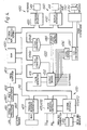
unit 2 is shown in block form in Figure 3. It comprises amicrocomputer 300 which may be implemented by means of a microprocessor and controls and co-ordinate the operation of the other parts of the circuitry. Connected to themicrocomputer 300 via adata bus 310 is amemory 320 in which data can be stored defining the desired characteristics of the stimulating pulses. This memory may be wholly read-only, part read/write and part read-only or wholly read/write (note that this is referring to memory in which the stimulating pulse data is stored; such memory is required for operation of the microprocessor, if such is used as themicrocomputer 300 may be provided separately, if desired and be, for example mask programmed). In the present case, where it is intended that the data is down-loaded from the system controller 1 to theunit 2, at least part of thememory 320 will require to be read/write memory and preferably, also, non-volatile so that the unit can be used remotely from the system controller 1, without requiring reprogramming between uses. For this purpose thememory 320 may be the nature such that it is inherently non-volatile, such as magnetic bubble memory or, for example, a low consumption CMOS memory with battery back-up or electrically alterable memory the latter being preferred. - Reading and writing operations to and from the
memory 320 are carried out by themicrocomputer 300 which carries out the function of loading the data into the memory and outputting it to aprogrammable pulse generator 330 which, in response to the data read out from thememory 320 generates a train of pulses as defined by the data, this in turn being connected to an output interface which drives the electrodes 2a. - It will be seen that the programmable pulse generator is connected to the
microcomputer 300 andmemory 320 by means of thedata bus 310. Also connected to the bus are anLCD display 340 and avoice synthesizer 350 which drives aloudspeaker 351. - The
programmable pulse generator 330 comprises apulse generator 331 which converts data onbus 310 to pulse characteristics and delivers the pulses so formed to outputdrive circuitry 332 which can provide twochannels 333a and 333b of output signals for theelectrodes 2. Two digital toanalog converters pulse generator 331 may be modulated to provide a particular envelope waveform at the associated outputs 333. - There are also provided a
manual level control 335 for the outputs to the electrodes and, aload sensing circuit 336 and analog todigital converter 337 which sense the loading on the electrodes connected to the output 33a and 333b and feed this information back in digital form to themicrocomputer 300 via thedata bus 310. - The device may thus be arranged to be responsive to changes in the patient's skin resistance. By this or other means [e.g. separate electrodes applied to the skin] it may also be possible to feed back information relating to muscle firming so as to optimise the manner of pulse generation vis-a-vis the intended purpose of stimulation.
- Thus the stimulus signal may be altered dynamically depending on the muscle response.
- The microcomputer may be programmed to be responsive from electromyographic signals from the patient by means of an electromyographic section 360 comprising a
signal processor 361 andpulse conditioning circuit 362. Thispulse conditioner 361 may also respond to an external trigger applied to aninput 363. - The
LCD display 340 and thevoice synthesizer 350 may be used by suitable programming of themicrocomputer 300 to output information such as instructions on the use of the stimulator, usage data and so forth to the user, programmer or patient. - Data, in particular defining the characteristics of the stimulating pulses which are to be generated, may be loaded into the memory from the system controller or other remote host via a
data transfer section 370. This includes the infra-red detector 5 and a demodulator/serial-to-parallel converter 371. A complementary arrangement of amodulator 372 and an infra-red transmitter 373 are provided so that data, e.g. statistical data relating to stimulation applied via theelectrode 2 may be returned to the system controller or host. Data may also be passed to and from the system controller or a remote host via the telephone lines e.g. by means of an acoustic coupler 374 (this being preferable from the portability point of view to a hard-wired modem) with associatedmodulator 375 anddemodulator 376. - Any suitable modulation scheme e.g. frequency shift keying may be used for both the infra-red and acoustic links.
- Figure 4 shows in block diagram form the system control unit 1 of the system. It will be seen that it is generally similar to the circuitry of Figure 3 but with extra and more flexible features. Those elements that perform functions equivalent to counterparts in Figure 3 have counterpart reference numerals but with the leading "3" changed to "4".
- As in the personal unit, with the system controller has
timing control circuitry 400 which, as with thepersonal unit 2, may be a specially-programmed microprocessor, a memory 420 for programme and data storage, a programmablestimulation pulse generator 430 and adata transfer section 470 exchanging data between the memory 420 and other devices. - The control unit is also provided with a number of user-
operable controls 480, suitably provided bykeyboard 481 andkeyboard interface 482 to programme themicrocomputer 400 and to preset the characteristics of the pulse trains to be generated by each channel of theprogrammable generator 430. These characteristics may include the intervals pulses, the lengths of the pulses, the mean repetition rate of the pulses, envelope modulation of the pulses into bursts. Various other controls may be provided to control the operation of the unit and to provide, for example, that the characteristics of a particular pulse stimulation pattern, once established, can be stored in the memory 1 and later be retrieved to set theprogrammable pulse generator 430. This generator, in this example, has 8 parallel output channels, all fed with the same pulse train (although the generator may provide for separate pulse trains for each channel) and may have an independent level control for each channel. These level controls may be digitally controllable. - The
microcomputer 400 may be suitably programmed so as to be responsive to user input from the keyboard 45 to carry out a number of tasks, including:- - 1. The definition/setting up of the characteristics of stimulating pulse sequences, these characteristics being stored in the microcomputer memory 420 and, according to the users, requirements either used to generate a stimulating pulse train by the
pulse generator 430 or to be transferred via thedata transfer section 470 to a remote device such as a remote host or one of thepersonal units 2, to a remote or to a data file in a mass storage unit such as disc drive (not shown). - 2. To initiate the storage/retrieval of data to/from a remote host via the
section 470, or to thepersonal unit 2 or a data file in a mass storage unit. - 3. To instruct the
microcomputer 400 to display ondisplay 441 pulse stimulation train data or treatment data, file directories and so forth. - It will be seen that the
pulse generator 430 of the system controller is of similar structure to thepulse generator 330 of Figure 3 and is intended to operate in a similar manner. It has apulse generator 431 which takes digital data from thedata bus 410 and converts this to stimulating pulses which are distributed to the eight output channels by means of theoutput driving circuitry 432. Theload sensor 436 is adapted to take information from each of the eight output channels rather than the two output channels of Figure 3. - The system controller 1 also includes an EMG
responsive section 460 corresponding to that of Figure 3 and a voice synthesizer and associatedloudspeaker 450 corresponding to that of Figure 3. - It will be seen that the data transfer section includes a
parallel interface 477 for rapid, parallel transfer of data to and from e.g. a computer, a mass storage device such as a disc-or tape-store, or any other appropriate data logging, storage or processing system. - The stimulation pulse trains which are produced by the
personal unit 2 and by the unit 1 (in . the latter case, whether for immediate use using theprogrammable pulse generator 430 or to be down-loaded as data to one of the personal units 2), may be such as to provide both functional stimulation, that is stimulation which causes muscle fibres to contract and relax in a predetermined way, or may be the "trophic" stimulation mentioned above, that is stimulation with pulses whose characteristics are chosen such that they effect a long term structural or functional change in the muscle fibres. - In order to treat certain types of muscular disorder, it may be necessary to bring about long term changes In-the structure and/or function of the muscle fibre as well as to provide for functional stimulation and it is therefore envisaged that a course of treatment may comprise a mix of trophic stimulation and functional stimulation with more frequent use of trophic stimulation at the early stages of the treatment and or frequent use of functional stimulation towards the end. In some cases it may necessary for the start of treatment to consist wholly of trophic stimulation at the start.
- It is envisaged that such a course of treatment comprising data defining sets of pulse series, some of which provide functional stimulation, and some of which provide trophic stimulation may be programmed into the
personal unit 2 by the control unit 1 so that the patient may take the personal unit away and use it for treatment at home. The data defining the stimulation to be applied may be up-dated from time to time by taking theunit 2 back to the unit 1 and down-loading the up-dated information. Preferably, therefore, thepersonal unit 2 is so programmed as to store in its memory 420 an indication of the characteristics of the current stimulation pattern(s) and a record of the number of times that the patient has applied them so that these items of information may be transmitted via the data link to the control unit 1 and thereby enabled the correct data for the next phase of treatment to be identified and down-loaded to thepersonal unit 2. - As mentioned above, the control unit 1 has an interface 4 interfacing with a computer such as a personal, desktop or personal computer, preferably of the type which has disc drives or other non-volatile storage so that a database of stimulation pulse data can be stored and specific files retrieved and loaded into the memory 41 of the unit 1 so as to be available for the direct generation of pulses by the
pulse generator 430 or for down-loading to thepersonal units 2. The computer to which the control unit 1 is linked, preferably by a industry-standard parallel or serial link such as the RS232 (serial) or Centronics interface (parallel) may be programmed to accept data files of pulse stimulation data from the control unit 1 and of any other data which can be selected by the operator of the unit via the section 380 and which it would be convenient to store in a mass storage device and retrieve at a later date, for example patient data, treatment details and so forth. - Both the
personal unit 2 and the control unit 1 may be provided with a modem for exchanging data with one another or with a remote computer data base so as to enable stimulation pulse data and other useful data to be stored and or processed by the remote computer or exchanged between thepersonal unit 2 and the control 1 when it is not possible to bring them physically together. To assist in achieving this, thepersonal unit 2 may have a microphone and loudspeaker arranged so that they can be held against the handset of a standard telephone, in which case as with conventional portable modems, these items may be surrounded by soundproofing material to shut out extraneous noise and, instead or as well, thepersonal units 2 and the control unit 1 may be provided with an internal modem directly connected to a standard telephone jack plug. - It will be apparent from the above that once suitable treatment regimes have been established, the pulse data and other relevant information relating to these may be transferred direct to the
personal units 2 from a remote or on-site computer without the intervention of the controller 1. - The overall specification of the facilities of the controller 1 is as follows:-
- The overall specification of the facilities of the controller 1 is as follows:-
- Controls 8 independent amplitude slide controls 1 Rise/Fall time control Full numeric keypad and parameter selection and display controls.
- Power Rechargeable NiCd Batteries or Power Supply.

- Interfaces 1. Optical link for
personal stimulator 2 - 2. Parallel link with research unit 3.
- 3. External independent trigger for evaluation of functional stimulation.
- 4. Parallel link with Personal Computer to allow infinite selection of user program files.
- Interfaces 1. Optical link for
- The following points should be noted :
- (a) As a stand-alone instrument the system controller may be used in Hospitals and Clinics with direct therapeutic application.
- (b) A successful treatment regime may be easily down-loaded to a personal unit instrument for continued treatment of patients at home.
- (c) When connected to the research unit 3 the instrument's eight outputs are under full control of the unit 3 and its associated computer.
- (d) When connected direct to a computer the instrument may have an infinite number of patient specific programs or trophic codes down loaded to it or via its optic link to a
personal stimulator 2. - (e) The optical link could be further expanded to interface with a modem to allow remote programming.
- The overall specifications of the
personal units 2 are as follows:- - 2 channel portable microcomputer controlled electronic neuromuscular stimulator.

- All parameters optically programmable on infra-red link with host machine/system controller. Failure to program or subsequent accidental program loss will trigger an error detection indicator.
- Ootion : trophic code and/or functional code replaceable memory cartridges.
- The research unit 3 is adapted to be used in association with the system controller 1 to provide an 8 channel sophisticated computer driven neuromuscular stimulation controller for extensive research application; it may have inter alia RS232 and IEEE 488 interfaces for communication with the host computer which is to be used to control it, as well as a suitable e.g. parallel interface for communicating with the system controller 1.
- The instrument will be supplied with elaborate software control modules to run on its host computer and will be controlled by it over standard interfaces.
- The research unit instrument interfaces directly to the controller 1 and captures full control over its eight stimulation outputs.
- Each channel is totally independent and may be controlled in frequency pulse width, contraction time, relaxation time, rise time, fall time and amplitude. sophisticated envelope waveforms for the stimulation amplitude may be generated graphically on the host computer. Precision timing between stimulation channels may be set-up thus allowing elaborate functional stimulation and gait control experiments.
- Alternately the research unit may be used to generate and emulate exceedingly complex trophic code stimulation patterns used in experimental research into the fundamentals of neurophysiology.

- Interface operates in half-duplex mode.
- A communication protocol for use by this link and for other data transfers between the units may be based on the standard ASCII codes and comprise a series of control codes and parameter codes as follows:-

Claims (13)


Applications Claiming Priority (2)
| Application Number | Priority Date | Filing Date | Title |
|---|---|---|---|
| GB8510832 | 1985-04-29 | ||
| GB858510832A GB8510832D0 (en) | 1985-04-29 | 1985-04-29 | Electrical stimulation of muscle |
Publications (3)
| Publication Number | Publication Date |
|---|---|
| EP0201271A2 true EP0201271A2 (en) | 1986-11-12 |
| EP0201271A3 EP0201271A3 (en) | 1987-11-04 |
| EP0201271B1 EP0201271B1 (en) | 1996-05-08 |
Family
ID=10578365
Family Applications (1)
| Application Number | Title | Priority Date | Filing Date |
|---|---|---|---|
| EP86303262A Expired - Lifetime EP0201271B1 (en) | 1985-04-29 | 1986-04-29 | Improvements in, or relating to, the electrical stimulation of muscle |
Country Status (5)
| Country | Link |
|---|---|
| US (1) | US4832033A (en) |
| EP (1) | EP0201271B1 (en) |
| AT (1) | ATE137679T1 (en) |
| DE (1) | DE3650521T2 (en) |
| GB (2) | GB8510832D0 (en) |
Cited By (6)
| Publication number | Priority date | Publication date | Assignee | Title |
|---|---|---|---|---|
| EP0316280A1 (en) * | 1987-11-12 | 1989-05-17 | Medicompex S.A. | Installation for electrical neuromuscular stimulation |
| DE3833168A1 (en) * | 1988-09-27 | 1990-03-29 | Steindorf Susanne Ruth | Method for the function monitoring and/or parameter setting of an electromedical therapy apparatus |
| EP0391428A2 (en) * | 1989-04-07 | 1990-10-10 | Omron Corporation | Transcutaneous electric nerve stimulater |
| WO1993024176A1 (en) * | 1992-05-23 | 1993-12-09 | Keith Edward Tippey | Electrical stimulation for treatment of incontinence and other neuro-muscular disorders |
| ES2304272A1 (en) * | 2005-10-06 | 2008-10-01 | Hiperthermia Medical Group, S.R.L. | Molecular bio-resonance device (Machine-translation by Google Translate, not legally binding) |
| WO2018178488A1 (en) * | 2017-03-31 | 2018-10-04 | Medical Fitness Technology, Sl | Portable electrostimulator |
Families Citing this family (147)
| Publication number | Priority date | Publication date | Assignee | Title |
|---|---|---|---|---|
| US5935099A (en) | 1992-09-09 | 1999-08-10 | Sims Deltec, Inc. | Drug pump systems and methods |
| US6241704B1 (en) | 1901-11-22 | 2001-06-05 | Sims Deltec, Inc. | Drug pump systems and methods |
| US5338157B1 (en) * | 1992-09-09 | 1999-11-02 | Sims Deltec Inc | Systems and methods for communicating with ambulat |
| DE3671377D1 (en) * | 1985-04-03 | 1990-06-28 | Medicompex S A | DEVICE FOR ELECTROSTIMULATING NERVES AND MUSCLES. |
| CA1278045C (en) * | 1985-05-15 | 1990-12-18 | Wu Dumin | Apparatus and method for generating vital information signals |
| US5041974A (en) * | 1988-10-26 | 1991-08-20 | Walker Judith B | Multichannel stimulator for tuned stimulation |
| US4976264A (en) * | 1989-05-10 | 1990-12-11 | Therapeutic Technologies Inc. | Power muscle stimulator |
| DE3924214A1 (en) * | 1989-07-21 | 1991-01-24 | Mueller & Sebastiani Elek Gmbh | METHOD AND SYSTEM FOR THE DATA EVALUATION OF LONG-TERM ECG DEVICES |
| IT1240362B (en) * | 1990-03-30 | 1993-12-10 | Medisan S.L.R. | PROCEDURE FOR THE ELECTROSTIMULATION OF A MUSCLE MASS IN ORDER TO IMPROVE THE AESTHETIC ASPECT, AND APPARATUS FOR IMPLEMENTING THE PROCEDURE |
| US5350414A (en) * | 1991-12-10 | 1994-09-27 | Electro Science Technologies, Inc. | Local application microprocessor based nerve and muscle stimulator |
| US5300096A (en) * | 1992-06-03 | 1994-04-05 | Hall H Eugene | Electromyographic treatment device |
| US5233987A (en) * | 1992-07-09 | 1993-08-10 | Empi, Inc. | System and method for monitoring patient's compliance |
| US5590648A (en) * | 1992-11-30 | 1997-01-07 | Tremont Medical | Personal health care system |
| US5719761A (en) † | 1993-01-15 | 1998-02-17 | Alaris Medical Systems, Inc. | Configuration control system for configuring multiple biomedical devices |
| US5487759A (en) * | 1993-06-14 | 1996-01-30 | Bastyr; Charles A. | Nerve stimulating device and associated support device |
| AU7323994A (en) * | 1993-07-13 | 1995-02-13 | Sims Deltec, Inc. | Medical pump and method of programming |
| US5368562A (en) * | 1993-07-30 | 1994-11-29 | Pharmacia Deltec, Inc. | Systems and methods for operating ambulatory medical devices such as drug delivery devices |
| US5836993A (en) * | 1996-05-16 | 1998-11-17 | Heartstream, Inc. | Electrotherapy device control system and method |
| JP4113585B2 (en) | 1996-06-13 | 2008-07-09 | ザ・ユニバーシティ・オブ・マンチェスター | Muscle stimulation |
| US6865423B2 (en) | 1996-06-13 | 2005-03-08 | The Victoria University Of Manchester | Stimulation of muscles |
| IT1285754B1 (en) * | 1996-07-12 | 1998-06-18 | Piana Cosmetici Spa | EQUIPMENT FOR THE AESTHETIC TREATMENT OF PARTS OF THE HUMAN BODY |
| US5687717A (en) * | 1996-08-06 | 1997-11-18 | Tremont Medical, Inc. | Patient monitoring system with chassis mounted or remotely operable modules and portable computer |
| US5810747A (en) * | 1996-08-21 | 1998-09-22 | Interactive Remote Site Technology, Inc. | Remote site medical intervention system |
| GB2324965B (en) * | 1997-05-09 | 2001-05-23 | Mediwave Res Ltd | Muscle restructuring system |
| US6070102A (en) | 1998-04-29 | 2000-05-30 | Medtronic, Inc. | Audible sound confirmation of programming an implantable medical device |
| US6370433B1 (en) | 1998-04-29 | 2002-04-09 | Medtronic, Inc. | Interrogation of an implantable medical device using broadcast audible sound communication |
| US6082367A (en) * | 1998-04-29 | 2000-07-04 | Medtronic, Inc. | Audible sound communication from an implantable medical device |
| US6450172B1 (en) | 1998-04-29 | 2002-09-17 | Medtronic, Inc. | Broadcast audible sound communication from an implantable medical device |
| US6216038B1 (en) | 1998-04-29 | 2001-04-10 | Medtronic, Inc. | Broadcast audible sound communication of programming change in an implantable medical device |
| US5891180A (en) * | 1998-04-29 | 1999-04-06 | Medtronic Inc. | Interrogation of an implantable medical device using audible sound communication |
| US6594527B2 (en) * | 1998-09-18 | 2003-07-15 | Nexmed Holdings, Inc. | Electrical stimulation apparatus and method |
| EP1022034A1 (en) * | 1999-01-19 | 2000-07-26 | Manfred Dr. Leubner | Method and device for stimulating muscles or nervous tissue |
| US7270274B2 (en) * | 1999-10-04 | 2007-09-18 | Hand Held Products, Inc. | Imaging module comprising support post for optical reader |
| US6692430B2 (en) * | 2000-04-10 | 2004-02-17 | C2Cure Inc. | Intra vascular imaging apparatus |
| IL135571A0 (en) * | 2000-04-10 | 2001-05-20 | Doron Adler | Minimal invasive surgery imaging system |
| US6393328B1 (en) * | 2000-05-08 | 2002-05-21 | International Rehabilitative Sciences, Inc. | Multi-functional portable electro-medical device |
| US6514200B1 (en) | 2000-05-17 | 2003-02-04 | Brava, Llc | Patient compliance monitor |
| US6730024B2 (en) * | 2000-05-17 | 2004-05-04 | Brava, Llc | Method and apparatus for collecting patient compliance data including processing and display thereof over a computer network |
| SE516707C2 (en) * | 2000-05-30 | 2002-02-19 | Volvo Lastvagnar Ab | Power units for motor vehicles |
| US7047338B1 (en) * | 2000-07-18 | 2006-05-16 | Igt | Configurable hot-swap communication |
| US20050251061A1 (en) * | 2000-11-20 | 2005-11-10 | Schuler Eleanor L | Method and system to record, store and transmit waveform signals to regulate body organ function |
| US6633779B1 (en) * | 2000-11-27 | 2003-10-14 | Science Medicus, Inc. | Treatment of asthma and respiratory disease by means of electrical neuro-receptive waveforms |
| US6564103B2 (en) * | 2000-12-01 | 2003-05-13 | Visionquest Industries, Inc. | Electrical stimulator and method of use |
| GB2370507B (en) * | 2000-12-23 | 2003-07-30 | Nuron Ltd | Apparatus for the diagnosis and therapy of neuro-muscular and other tissue disorders |
| ITRN20010004A1 (en) * | 2001-01-25 | 2001-04-26 | Vupiesse Italia S R L | PORTABLE ELECTROSTIMULATOR DEVICE AND RELATED APPARATUS |
| US6775573B2 (en) * | 2001-03-01 | 2004-08-10 | Science Medicus Inc. | Electrical method to control autonomic nerve stimulation of gastrointestinal tract |
| WO2002073503A2 (en) * | 2001-03-14 | 2002-09-19 | Baxter International Inc. | Internet based therapy management system |
| US20020184369A1 (en) * | 2001-05-31 | 2002-12-05 | Parkinson Steven William | Appointment scheme for redistributing service access |
| KR100456038B1 (en) * | 2001-06-04 | 2004-11-09 | 임재중 | The bio-feedback system |
| CA2469773A1 (en) | 2001-12-11 | 2003-07-03 | C2Cure Inc. | Apparatus, method and system for intravascular photographic imaging |
| US8775196B2 (en) | 2002-01-29 | 2014-07-08 | Baxter International Inc. | System and method for notification and escalation of medical data |
| US10173008B2 (en) | 2002-01-29 | 2019-01-08 | Baxter International Inc. | System and method for communicating with a dialysis machine through a network |
| US20040010425A1 (en) * | 2002-01-29 | 2004-01-15 | Wilkes Gordon J. | System and method for integrating clinical documentation with the point of care treatment of a patient |
| US8250483B2 (en) | 2002-02-28 | 2012-08-21 | Smiths Medical Asd, Inc. | Programmable medical infusion pump displaying a banner |
| US8504179B2 (en) | 2002-02-28 | 2013-08-06 | Smiths Medical Asd, Inc. | Programmable medical infusion pump |
| US20030222548A1 (en) * | 2002-05-31 | 2003-12-04 | Richardson William R. | Storage device for health care facility |
| US8234128B2 (en) | 2002-04-30 | 2012-07-31 | Baxter International, Inc. | System and method for verifying medical device operational parameters |
| US20080077192A1 (en) * | 2002-05-03 | 2008-03-27 | Afferent Corporation | System and method for neuro-stimulation |
| WO2003098913A2 (en) * | 2002-05-16 | 2003-11-27 | Cbyond Inc. | Miniature camera head |
| US20040098065A1 (en) * | 2002-11-19 | 2004-05-20 | Alliance Health Products, Llc | Transcutaneous nerve and muscle stimulator and method of using the same |
| US6856837B2 (en) * | 2002-11-20 | 2005-02-15 | O'kelly Gregory C. | Method and device for electrochemically building of muscle |
| JP2007500576A (en) * | 2003-05-16 | 2007-01-18 | サイエンス・メディカス・インコーポレイテッド | Respiration control using neuro-electrically encoded signals |
| US20060064137A1 (en) * | 2003-05-16 | 2006-03-23 | Stone Robert T | Method and system to control respiration by means of simulated action potential signals |
| US20050261747A1 (en) * | 2003-05-16 | 2005-11-24 | Schuler Eleanor L | Method and system to control respiration by means of neuro-electrical coded signals |
| US20060111755A1 (en) * | 2003-05-16 | 2006-05-25 | Stone Robert T | Method and system to control respiration by means of neuro-electrical coded signals |
| AU2004251722A1 (en) * | 2003-06-18 | 2005-01-06 | Neurosignal Technologies, Inc. | Skeletal muscle control by means of neuro-electrical signals |
| US20050137652A1 (en) * | 2003-12-19 | 2005-06-23 | The Board of Regents of the University of Texas at Dallas | System and method for interfacing cellular matter with a machine |
| US20090198293A1 (en) * | 2003-12-19 | 2009-08-06 | Lawrence Cauller | Microtransponder Array for Implant |
| US8954336B2 (en) | 2004-02-23 | 2015-02-10 | Smiths Medical Asd, Inc. | Server for medical device |
| GB2411594A (en) * | 2004-03-05 | 2005-09-07 | Thi Ngoc Phuong Nguyen | Microprocessor controlled electro-stimulation of facial muscles via skin electrodes |
| US8936560B2 (en) * | 2004-03-10 | 2015-01-20 | Vision Quest Industries Incorporated | Bracing and electrostimulation for arthritis |
| KR100630058B1 (en) * | 2004-06-01 | 2006-09-27 | 삼성전자주식회사 | Low frequency electrical stimulus device built-in mobile phone and the control method |
| US7300397B2 (en) * | 2004-07-29 | 2007-11-27 | C2C Cure, Inc. | Endoscope electronics assembly |
| US20060164510A1 (en) * | 2005-01-24 | 2006-07-27 | Doron Adler | Sensor with narrow mounting profile |
| US20070185409A1 (en) * | 2005-04-20 | 2007-08-09 | Jianping Wu | Method and system for determining an operable stimulus intensity for nerve conduction testing |
| CA2544331A1 (en) * | 2005-04-20 | 2006-10-20 | Excel-Tech Ltd. | Device, method and stimulus unit for testing neuromuscular function |
| US7319902B2 (en) * | 2005-05-09 | 2008-01-15 | O'kelly Gregory | Method and device for electrochemical rejuvenation of skin and underlying tissue, and muscle building |
| WO2007032786A2 (en) * | 2005-05-11 | 2007-03-22 | Medical Technologies Unlimited, Inc. | Apparatus for converting electromyographic (emg) signals for transference to a personal computer |
| US8972017B2 (en) | 2005-11-16 | 2015-03-03 | Bioness Neuromodulation Ltd. | Gait modulation system and method |
| US7899556B2 (en) | 2005-11-16 | 2011-03-01 | Bioness Neuromodulation Ltd. | Orthosis for a gait modulation system |
| US8209022B2 (en) * | 2005-11-16 | 2012-06-26 | Bioness Neuromodulation Ltd. | Gait modulation system and method |
| US20070191912A1 (en) * | 2006-02-10 | 2007-08-16 | Vision Quest Industries, Inc. | Interactive electrical stimulator device and server-based support system |
| US8788049B2 (en) | 2006-05-01 | 2014-07-22 | Bioness Neuromodulation Ltd. | Functional electrical stimulation systems |
| US7844070B2 (en) * | 2006-05-30 | 2010-11-30 | Sonitus Medical, Inc. | Methods and apparatus for processing audio signals |
| US20120243714A9 (en) * | 2006-05-30 | 2012-09-27 | Sonitus Medical, Inc. | Microphone placement for oral applications |
| US8149131B2 (en) | 2006-08-03 | 2012-04-03 | Smiths Medical Asd, Inc. | Interface for medical infusion pump |
| US8965707B2 (en) | 2006-08-03 | 2015-02-24 | Smiths Medical Asd, Inc. | Interface for medical infusion pump |
| US8435206B2 (en) | 2006-08-03 | 2013-05-07 | Smiths Medical Asd, Inc. | Interface for medical infusion pump |
| US8858526B2 (en) | 2006-08-03 | 2014-10-14 | Smiths Medical Asd, Inc. | Interface for medical infusion pump |
| US8291912B2 (en) * | 2006-08-22 | 2012-10-23 | Sonitus Medical, Inc. | Systems for manufacturing oral-based hearing aid appliances |
| CA2663017C (en) * | 2006-09-08 | 2014-03-25 | Sonitus Medical, Inc. | Methods and apparatus for treating tinnitus |
| US20080129517A1 (en) * | 2006-11-24 | 2008-06-05 | Ventrassist Pty Ltd | Control System With Alarm |
| US8270638B2 (en) * | 2007-05-29 | 2012-09-18 | Sonitus Medical, Inc. | Systems and methods to provide communication, positioning and monitoring of user status |
| US20080304677A1 (en) * | 2007-06-08 | 2008-12-11 | Sonitus Medical Inc. | System and method for noise cancellation with motion tracking capability |
| US7630771B2 (en) * | 2007-06-25 | 2009-12-08 | Microtransponder, Inc. | Grooved electrode and wireless microtransponder system |
| US20090028352A1 (en) * | 2007-07-24 | 2009-01-29 | Petroff Michael L | Signal process for the derivation of improved dtm dynamic tinnitus mitigation sound |
| US20120235632A9 (en) * | 2007-08-20 | 2012-09-20 | Sonitus Medical, Inc. | Intra-oral charging systems and methods |
| US8433080B2 (en) * | 2007-08-22 | 2013-04-30 | Sonitus Medical, Inc. | Bone conduction hearing device with open-ear microphone |
| US8224013B2 (en) | 2007-08-27 | 2012-07-17 | Sonitus Medical, Inc. | Headset systems and methods |
| US7682303B2 (en) | 2007-10-02 | 2010-03-23 | Sonitus Medical, Inc. | Methods and apparatus for transmitting vibrations |
| US8457757B2 (en) | 2007-11-26 | 2013-06-04 | Micro Transponder, Inc. | Implantable transponder systems and methods |
| US9089707B2 (en) | 2008-07-02 | 2015-07-28 | The Board Of Regents, The University Of Texas System | Systems, methods and devices for paired plasticity |
| WO2009070705A2 (en) * | 2007-11-26 | 2009-06-04 | Microtransponder Inc. | Transfer coil architecture |
| AU2008329652B2 (en) * | 2007-11-26 | 2011-08-04 | Micro Transponder Inc. | Implanted driver with resistive charge balancing |
| US8795172B2 (en) * | 2007-12-07 | 2014-08-05 | Sonitus Medical, Inc. | Systems and methods to provide two-way communications |
| US7974845B2 (en) | 2008-02-15 | 2011-07-05 | Sonitus Medical, Inc. | Stuttering treatment methods and apparatus |
| US8270637B2 (en) * | 2008-02-15 | 2012-09-18 | Sonitus Medical, Inc. | Headset systems and methods |
| US8023676B2 (en) | 2008-03-03 | 2011-09-20 | Sonitus Medical, Inc. | Systems and methods to provide communication and monitoring of user status |
| US8150075B2 (en) | 2008-03-04 | 2012-04-03 | Sonitus Medical, Inc. | Dental bone conduction hearing appliance |
| US20090226020A1 (en) * | 2008-03-04 | 2009-09-10 | Sonitus Medical, Inc. | Dental bone conduction hearing appliance |
| US20090270673A1 (en) * | 2008-04-25 | 2009-10-29 | Sonitus Medical, Inc. | Methods and systems for tinnitus treatment |
| US8133197B2 (en) | 2008-05-02 | 2012-03-13 | Smiths Medical Asd, Inc. | Display for pump |
| US10089443B2 (en) | 2012-05-15 | 2018-10-02 | Baxter International Inc. | Home medical device systems and methods for therapy prescription and tracking, servicing and inventory |
| US8057679B2 (en) | 2008-07-09 | 2011-11-15 | Baxter International Inc. | Dialysis system having trending and alert generation |
| US8554579B2 (en) | 2008-10-13 | 2013-10-08 | Fht, Inc. | Management, reporting and benchmarking of medication preparation |
| US8204601B2 (en) * | 2008-10-20 | 2012-06-19 | Seaboard Assets Corp. | Cranial electrostimulation device for treatment of polysubstance addiction and method of use |
| US8876696B2 (en) | 2009-03-04 | 2014-11-04 | Eugene Mikhailenok | Device, system and method for improving erectile functions in males |
| US20100273614A1 (en) * | 2009-04-22 | 2010-10-28 | Joseph Lastik | Method for Passive Abdominal Exercise Using Elastic Exercise Band |
| CN102470246B (en) * | 2009-07-10 | 2015-08-05 | 都柏林大学,爱尔兰都柏林国立大学 | Stimulate the method and apparatus of psoas muscle and abdominal muscle |
| AU2010301027B2 (en) | 2009-10-02 | 2014-11-06 | Soundmed, Llc | Intraoral appliance for sound transmission via bone conduction |
| US8938303B1 (en) | 2010-06-01 | 2015-01-20 | Brandie Matsen | Restless leg therapeutic device |
| US9669226B2 (en) | 2010-09-07 | 2017-06-06 | Empi, Inc. | Methods and systems for reducing interference in stimulation treatment |
| EP2446865A1 (en) * | 2010-10-28 | 2012-05-02 | Louise Mohn | Thermostimulation apparatus |
| US8868217B2 (en) | 2011-06-27 | 2014-10-21 | Bioness Neuromodulation Ltd. | Electrode for muscle stimulation |
| EP2736588A4 (en) | 2011-07-27 | 2015-06-10 | Vision Quest Ind Inc Dba Vq Orthocare | Electrostimulation system |
| DE102011115906A1 (en) * | 2011-10-14 | 2013-04-18 | Wellcomet Gmbh | System for generating ultrasonic waves and method for configuring an ultrasound system |
| NZ739406A (en) | 2012-08-31 | 2019-07-26 | Baxter Corp Englewood | Medication requisition fulfillment system and method |
| KR102078768B1 (en) | 2012-10-26 | 2020-02-19 | 백스터 코포레이션 잉글우드 | Improved image acquisition for medical dose preparation system |
| EP3453377A1 (en) | 2012-10-26 | 2019-03-13 | Baxter Corporation Englewood | Improved work station for medical dose preparation system |
| WO2014089331A1 (en) | 2012-12-06 | 2014-06-12 | Ossur Hf | Electrical stimulation for orthopedic devices |
| SG10201609076XA (en) | 2013-01-28 | 2016-12-29 | Smiths Medical Asd Inc | Medication safety devices and methods |
| US9072898B2 (en) | 2013-03-14 | 2015-07-07 | CyMedica, Inc. | System and methods for treating or supporting human joints or a portion of the human body |
| US8870798B2 (en) | 2013-03-14 | 2014-10-28 | CyMedica, Inc. | Systems and methods for treating human joints |
| US9257763B2 (en) | 2013-07-02 | 2016-02-09 | Gyrus Acmi, Inc. | Hybrid interconnect |
| US9510739B2 (en) | 2013-07-12 | 2016-12-06 | Gyrus Acmi, Inc. | Endoscope small imaging system |
| US9867985B2 (en) | 2014-03-24 | 2018-01-16 | Bioness Inc. | Systems and apparatus for gait modulation and methods of use |
| NZ727697A (en) | 2014-06-30 | 2022-05-27 | Baxter Corp Englewood | Managed medical information exchange |
| EP3164188B1 (en) * | 2014-07-03 | 2023-10-18 | Boston Scientific Neuromodulation Corporation | Neurostimulation system with flexible patterning |
| US11107574B2 (en) | 2014-09-30 | 2021-08-31 | Baxter Corporation Englewood | Management of medication preparation with formulary management |
| US11575673B2 (en) | 2014-09-30 | 2023-02-07 | Baxter Corporation Englewood | Central user management in a distributed healthcare information management system |
| WO2016090091A1 (en) | 2014-12-05 | 2016-06-09 | Baxter Corporation Englewood | Dose preparation data analytics |
| AU2016226164A1 (en) | 2015-03-03 | 2017-10-19 | Baxter Corporation Englewood | Pharmacy workflow management with integrated alerts |
| WO2016207206A1 (en) | 2015-06-25 | 2016-12-29 | Gambro Lundia Ab | Medical device system and method having a distributed database |
| CA3010880A1 (en) | 2016-01-11 | 2017-07-20 | Bioness Inc. | Systems and apparatus for gait modulation and methods of use |
| UY36937A (en) | 2016-03-31 | 2017-11-30 | Medecell S A | PROCESS TO ESTABLISH A MUSCLE ELECTRO-STIMULATION PROTOCOL, AND THE RESPECTIVE MUSCLE ELECTRO-STIMULATION PORTABLE EQUIPMENT USING THE REFERRED PROTOCOL |
| KR102476516B1 (en) | 2016-12-21 | 2022-12-09 | 감브로 룬디아 아베 | A medical device system that includes an information technology infrastructure with secure cluster domains supporting external domains. |
| US20200323461A1 (en) | 2017-10-20 | 2020-10-15 | Indian Institute Of Technology, Guwahati | Point-of-care system for detection of the physical stress at different parts of body |
Citations (9)
| Publication number | Priority date | Publication date | Assignee | Title |
|---|---|---|---|---|
| DE2908365A1 (en) * | 1979-03-03 | 1980-09-11 | Pichl & Schulte Datron Elect | Diagnostic and therapeutic stimulating appts. for paralysed muscles - has pulse generating circuit with changeover switch, generating periodical pulse trains of opposite sign with DC zero compensation |
| DE3207050A1 (en) * | 1982-02-26 | 1983-09-08 | Siemens AG, 1000 Berlin und 8000 München | MEDICAL DEVICE FOR PHYSICAL THERAPY, ESPECIALLY ELECTROMEDICAL STIMULATING DEVICE |
| US4505275A (en) * | 1977-09-15 | 1985-03-19 | Wu Chen | Treatment method and instrumentation system |
| US4532938A (en) * | 1983-05-04 | 1985-08-06 | Theratronics, Inc. | Electrotherapy apparatus |
| EP0155815A2 (en) * | 1984-03-13 | 1985-09-25 | Bio Medical Research Limited | Electrical stimulation of muscle |
| US4543955A (en) * | 1983-08-01 | 1985-10-01 | Cordis Corporation | System for controlling body implantable action device |
| EP0165049A2 (en) * | 1984-06-15 | 1985-12-18 | Empi, Inc. | Programmable functional electrical stimulation system |
| US4593955A (en) * | 1983-06-14 | 1986-06-10 | Robert Bosch Gmbh | Yaw-compensated vehicle anti-skid system |
| EP0197889A1 (en) * | 1985-04-03 | 1986-10-15 | Medicompex S.A. | Electrical neuro-muscular stimulation apparatus |
Family Cites Families (16)
| Publication number | Priority date | Publication date | Assignee | Title |
|---|---|---|---|---|
| US4232679A (en) * | 1977-01-26 | 1980-11-11 | Pacesetter Systems, Inc. | Programmable human tissue stimulator |
| US4165750A (en) * | 1978-03-18 | 1979-08-28 | Aleev Leonid S | Bioelectrically controlled electric stimulator of human muscles |
| DE2944542A1 (en) * | 1978-11-06 | 1980-05-14 | Medtronic Inc | DEVICE FOR PROGRAMMING IMPLANTED ELECTRONIC DEVICES, IN PARTICULAR PACER GENERATORS |
| AU536883B2 (en) * | 1979-03-12 | 1984-05-31 | Medtronic, Inc. | Computer system power control |
| US4503863A (en) * | 1979-06-29 | 1985-03-12 | Katims Jefferson J | Method and apparatus for transcutaneous electrical stimulation |
| US4365633A (en) * | 1980-02-22 | 1982-12-28 | Telectronics Pty. Ltd. | Patient-operated pacemaker programmer |
| US4361153A (en) * | 1980-05-27 | 1982-11-30 | Cordis Corporation | Implant telemetry system |
| US4485818A (en) * | 1980-11-14 | 1984-12-04 | Cordis Corporation | Multi-mode microprocessor-based programmable cardiac pacer |
| CA1175493A (en) * | 1981-04-30 | 1984-10-02 | Dennis G. Hepp | Keyboard-controlled microprocessor-based nerve stimulator |
| US4690144A (en) * | 1982-04-02 | 1987-09-01 | Medtronic, Inc. | Wireless transcutaneous electrical tissue stimulator |
| EP0107483B1 (en) * | 1982-10-29 | 1987-03-18 | Medtronic, Inc. | Pacemaker programmer with telemetric functions |
| CA1215128A (en) * | 1982-12-08 | 1986-12-09 | Pedro Molina-Negro | Electric nerve stimulator device |
| US4561443A (en) * | 1983-03-08 | 1985-12-31 | The Johns Hopkins University | Coherent inductive communications link for biomedical applications |
| US4569352A (en) * | 1983-05-13 | 1986-02-11 | Wright State University | Feedback control system for walking |
| US4502275A (en) * | 1983-10-13 | 1985-03-05 | Avco Corporation | Compressor air bleed override control system |
| US4558704A (en) * | 1983-12-15 | 1985-12-17 | Wright State University | Hand control system |
-
1985
- 1985-04-29 GB GB858510832A patent/GB8510832D0/en active Pending
-
1986
- 1986-04-28 US US06/856,235 patent/US4832033A/en not_active Expired - Lifetime
- 1986-04-29 EP EP86303262A patent/EP0201271B1/en not_active Expired - Lifetime
- 1986-04-29 AT AT86303262T patent/ATE137679T1/en active
- 1986-04-29 DE DE3650521T patent/DE3650521T2/en not_active Expired - Fee Related
- 1986-04-29 GB GB08610501A patent/GB2175806B/en not_active Expired
Patent Citations (9)
| Publication number | Priority date | Publication date | Assignee | Title |
|---|---|---|---|---|
| US4505275A (en) * | 1977-09-15 | 1985-03-19 | Wu Chen | Treatment method and instrumentation system |
| DE2908365A1 (en) * | 1979-03-03 | 1980-09-11 | Pichl & Schulte Datron Elect | Diagnostic and therapeutic stimulating appts. for paralysed muscles - has pulse generating circuit with changeover switch, generating periodical pulse trains of opposite sign with DC zero compensation |
| DE3207050A1 (en) * | 1982-02-26 | 1983-09-08 | Siemens AG, 1000 Berlin und 8000 München | MEDICAL DEVICE FOR PHYSICAL THERAPY, ESPECIALLY ELECTROMEDICAL STIMULATING DEVICE |
| US4532938A (en) * | 1983-05-04 | 1985-08-06 | Theratronics, Inc. | Electrotherapy apparatus |
| US4593955A (en) * | 1983-06-14 | 1986-06-10 | Robert Bosch Gmbh | Yaw-compensated vehicle anti-skid system |
| US4543955A (en) * | 1983-08-01 | 1985-10-01 | Cordis Corporation | System for controlling body implantable action device |
| EP0155815A2 (en) * | 1984-03-13 | 1985-09-25 | Bio Medical Research Limited | Electrical stimulation of muscle |
| EP0165049A2 (en) * | 1984-06-15 | 1985-12-18 | Empi, Inc. | Programmable functional electrical stimulation system |
| EP0197889A1 (en) * | 1985-04-03 | 1986-10-15 | Medicompex S.A. | Electrical neuro-muscular stimulation apparatus |
Non-Patent Citations (2)
| Title |
|---|
| BIOMEDIZINISCHE TECHNIK, vol. 30, no. 5, May 1985, pages 115-122, Berlin, DE; W. SCHUBERT: "Funktionelles Training schlaff gelähmter Muskulatur" * |
| G.C.Bitter:"Computer in today's world"; 1984, J.Wiley &Sons, Inc.;p.218 * |
Cited By (8)
| Publication number | Priority date | Publication date | Assignee | Title |
|---|---|---|---|---|
| EP0316280A1 (en) * | 1987-11-12 | 1989-05-17 | Medicompex S.A. | Installation for electrical neuromuscular stimulation |
| DE3833168A1 (en) * | 1988-09-27 | 1990-03-29 | Steindorf Susanne Ruth | Method for the function monitoring and/or parameter setting of an electromedical therapy apparatus |
| EP0391428A2 (en) * | 1989-04-07 | 1990-10-10 | Omron Corporation | Transcutaneous electric nerve stimulater |
| EP0391428A3 (en) * | 1989-04-07 | 1991-12-11 | Omron Corporation | Transcutaneous electric nerve stimulater |
| WO1993024176A1 (en) * | 1992-05-23 | 1993-12-09 | Keith Edward Tippey | Electrical stimulation for treatment of incontinence and other neuro-muscular disorders |
| AU674678B2 (en) * | 1992-05-23 | 1997-01-09 | Axelgaard Manufacturing Company, Ltd. | Electrical stimulation for treatment of incontinence and other neuro-muscular disorders |
| ES2304272A1 (en) * | 2005-10-06 | 2008-10-01 | Hiperthermia Medical Group, S.R.L. | Molecular bio-resonance device (Machine-translation by Google Translate, not legally binding) |
| WO2018178488A1 (en) * | 2017-03-31 | 2018-10-04 | Medical Fitness Technology, Sl | Portable electrostimulator |
Also Published As
| Publication number | Publication date |
|---|---|
| GB2175806A (en) | 1986-12-10 |
| DE3650521D1 (en) | 1996-06-13 |
| ATE137679T1 (en) | 1996-05-15 |
| GB8510832D0 (en) | 1985-06-05 |
| GB8610501D0 (en) | 1986-06-04 |
| GB2175806B (en) | 1988-09-07 |
| DE3650521T2 (en) | 1996-12-19 |
| EP0201271A3 (en) | 1987-11-04 |
| EP0201271B1 (en) | 1996-05-08 |
| US4832033A (en) | 1989-05-23 |
Similar Documents
| Publication | Publication Date | Title |
|---|---|---|
| EP0201271A2 (en) | Improvements in, or relating to, the electrical stimulation of muscle | |
| EP1513585B1 (en) | Optimizing implanted medical device performance | |
| EP1487335B1 (en) | Vaginal sensing and stimulating using 2-way wireless communications | |
| US6988005B2 (en) | Multi-functional portable electro-medical device | |
| JP7181593B2 (en) | compact muscle stimulator | |
| US4838272A (en) | Method and apparatus for adaptive closed loop electrical stimulation of muscles | |
| CA1209001A (en) | Method and apparatus for exercising | |
| US4642769A (en) | Method and apparatus for providing stimulated exercise of paralyzed limbs | |
| JPS62502383A (en) | electrical neuromuscular stimulator | |
| US20140330342A1 (en) | Smart phone application for providing neuro/muscular electro stimulation | |
| US7463930B2 (en) | Implantable medical device programmer module for use with existing clinical instrumentation | |
| EP0103491A1 (en) | Method and apparatus for providing feedback-controlled muscle stimulation | |
| US20060089683A1 (en) | Transcutaneous nerve and muscle stimulator and method of using the same | |
| DE60036379D1 (en) | DEVICE FOR THE TRANSCUTANEOUS WIRELESS ELECTRICAL STIMULATION OF NERVES OR MUSCLES IN MINIATURE VERSION | |
| EP0202258A1 (en) | Apparatus for delivering a prescriptive electricalsignal | |
| Robin et al. | A new implantable microstimulator dedicated to selective stimulation of the bladder | |
| Robin et al. | Implantable stimulation system dedicated for neural selective stimulation | |
| CN111803351A (en) | Affected limb local sensation triggering type cerebral apoplexy hindhand function rehabilitation therapeutic apparatus | |
| CN101161305A (en) | Healthcare device | |
| CN213130701U (en) | Affected limb local sensation triggering type cerebral apoplexy hindhand function rehabilitation therapeutic apparatus | |
| EP3988158A1 (en) | System for planning and/or controlling neuromodulation | |
| US9579504B2 (en) | Personalized patient controlled neurostimulation system | |
| CN117752946A (en) | Wireless pulse electric needle therapeutic instrument | |
| Cameron et al. | A bedside controller for use with micromodular electronic devices |
Legal Events
| Date | Code | Title | Description |
|---|---|---|---|
| PUAI | Public reference made under article 153(3) epc to a published international application that has entered the european phase |
Free format text: ORIGINAL CODE: 0009012 |
|
| AK | Designated contracting states |
Kind code of ref document: A2 Designated state(s): AT BE CH DE FR GB IT LI LU NL SE |
|
| PUAB | Information related to the publication of an a document modified or deleted |
Free format text: ORIGINAL CODE: 0009199EPPU |
|
| RA1 | Application published (corrected) |
Date of ref document: 19861217 Kind code of ref document: A2 |
|
| PUAL | Search report despatched |
Free format text: ORIGINAL CODE: 0009013 |
|
| RHK1 | Main classification (correction) |
Ipc: A61N 1/36 |
|
| AK | Designated contracting states |
Kind code of ref document: A3 Designated state(s): AT BE CH DE FR GB IT LI LU NL SE |
|
| 17P | Request for examination filed |
Effective date: 19880428 |
|
| 17Q | First examination report despatched |
Effective date: 19910419 |
|
| GRAA | (expected) grant |
Free format text: ORIGINAL CODE: 0009210 |
|
| RAP1 | Party data changed (applicant data changed or rights of an application transferred) |
Owner name: B.M.R. RESEARCH AND DEVELOPMENT LIMITED |
|
| AK | Designated contracting states |
Kind code of ref document: B1 Designated state(s): AT BE CH DE FR GB IT LI LU NL SE |
|
| PG25 | Lapsed in a contracting state [announced via postgrant information from national office to epo] |
Ref country code: IT Free format text: LAPSE BECAUSE OF FAILURE TO SUBMIT A TRANSLATION OF THE DESCRIPTION OR TO PAY THE FEE WITHIN THE PRE;WARNING: LAPSES OF ITALIAN PATENTS WITH EFFECTIVE DATE BEFORE 2007 MAY HAVE OCCURRED AT ANY TIME BEFORE 2007. THE CORRECT EFFECTIVE DATE MAY BE DIFFERENT FROM THE ONE RECORDED.SCRIBED TIME-LIMIT Effective date: 19960508 Ref country code: LI Effective date: 19960508 Ref country code: AT Effective date: 19960508 Ref country code: CH Effective date: 19960508 Ref country code: BE Effective date: 19960508 Ref country code: NL Free format text: LAPSE BECAUSE OF FAILURE TO SUBMIT A TRANSLATION OF THE DESCRIPTION OR TO PAY THE FEE WITHIN THE PRESCRIBED TIME-LIMIT Effective date: 19960508 Ref country code: FR Effective date: 19960508 |
|
| REF | Corresponds to: |
Ref document number: 137679 Country of ref document: AT Date of ref document: 19960515 Kind code of ref document: T |
|
| REF | Corresponds to: |
Ref document number: 3650521 Country of ref document: DE Date of ref document: 19960613 |
|
| PG25 | Lapsed in a contracting state [announced via postgrant information from national office to epo] |
Ref country code: SE Effective date: 19960808 |
|
| NLV1 | Nl: lapsed or annulled due to failure to fulfill the requirements of art. 29p and 29m of the patents act | ||
| EN | Fr: translation not filed | ||
| REG | Reference to a national code |
Ref country code: CH Ref legal event code: PL |
|
| PLBE | No opposition filed within time limit |
Free format text: ORIGINAL CODE: 0009261 |
|
| STAA | Information on the status of an ep patent application or granted ep patent |
Free format text: STATUS: NO OPPOSITION FILED WITHIN TIME LIMIT |
|
| PG25 | Lapsed in a contracting state [announced via postgrant information from national office to epo] |
Ref country code: LU Free format text: LAPSE BECAUSE OF NON-PAYMENT OF DUE FEES Effective date: 19970430 |
|
| 26N | No opposition filed | ||
| REG | Reference to a national code |
Ref country code: GB Ref legal event code: IF02 |
|
| PGFP | Annual fee paid to national office [announced via postgrant information from national office to epo] |
Ref country code: GB Payment date: 20020424 Year of fee payment: 17 |
|
| PGFP | Annual fee paid to national office [announced via postgrant information from national office to epo] |
Ref country code: DE Payment date: 20020628 Year of fee payment: 17 |
|
| PG25 | Lapsed in a contracting state [announced via postgrant information from national office to epo] |
Ref country code: GB Free format text: LAPSE BECAUSE OF NON-PAYMENT OF DUE FEES Effective date: 20030429 |
|
| PG25 | Lapsed in a contracting state [announced via postgrant information from national office to epo] |
Ref country code: DE Free format text: LAPSE BECAUSE OF NON-PAYMENT OF DUE FEES Effective date: 20031101 |
|
| GBPC | Gb: european patent ceased through non-payment of renewal fee | ||
| APAH | Appeal reference modified |
Free format text: ORIGINAL CODE: EPIDOSCREFNO |