EP0201023A1 - Osteosynthetic plate for compression stabilisation - Google Patents
Osteosynthetic plate for compression stabilisation Download PDFInfo
- Publication number
- EP0201023A1 EP0201023A1 EP86105850A EP86105850A EP0201023A1 EP 0201023 A1 EP0201023 A1 EP 0201023A1 EP 86105850 A EP86105850 A EP 86105850A EP 86105850 A EP86105850 A EP 86105850A EP 0201023 A1 EP0201023 A1 EP 0201023A1
- Authority
- EP
- European Patent Office
- Prior art keywords
- ramp
- bone
- compression
- screw
- plate
- Prior art date
- Legal status (The legal status is an assumption and is not a legal conclusion. Google has not performed a legal analysis and makes no representation as to the accuracy of the status listed.)
- Granted
Links
Images
Classifications
-
- A—HUMAN NECESSITIES
- A61—MEDICAL OR VETERINARY SCIENCE; HYGIENE
- A61B—DIAGNOSIS; SURGERY; IDENTIFICATION
- A61B17/00—Surgical instruments, devices or methods, e.g. tourniquets
- A61B17/56—Surgical instruments or methods for treatment of bones or joints; Devices specially adapted therefor
- A61B17/58—Surgical instruments or methods for treatment of bones or joints; Devices specially adapted therefor for osteosynthesis, e.g. bone plates, screws, setting implements or the like
- A61B17/68—Internal fixation devices, including fasteners and spinal fixators, even if a part thereof projects from the skin
- A61B17/80—Cortical plates, i.e. bone plates; Instruments for holding or positioning cortical plates, or for compressing bones attached to cortical plates
- A61B17/8004—Cortical plates, i.e. bone plates; Instruments for holding or positioning cortical plates, or for compressing bones attached to cortical plates with means for distracting or compressing the bone or bones
- A61B17/8014—Cortical plates, i.e. bone plates; Instruments for holding or positioning cortical plates, or for compressing bones attached to cortical plates with means for distracting or compressing the bone or bones the extension or compression force being caused by interaction of the plate hole and the screws
Definitions
- the invention relates to an osteosynthesis plate for the pressure stabilization of bone fragments.
- Clamping devices which, in conjunction with osteosynthesis plates, enable the pressure stabilization of the bone fragments.
- These include osteosynthesis plates; whose screw holes have inclined hole walls in the manner of an inclined plane, hereinafter referred to as ramps, so that when a bone screw is screwed in, the screw head slides on the ramp and thus a displacement of the plate in relation to the bone receiving the bone screw fragment causes.
- the largest possible compression path which is determined by the hole geometry and the thickness of the plate, is very short. - Larger compression stretches can be achieved with the help of a special clamping device, which is attached to the osteosynthesis plate.
- this device When this device is screwed to a bone fragment outside the bone plate, it has the disadvantage of a larger wound, greater surgical effort and a longer operating time. If it is attached in the area of the osteosynthesis plate in connection with an elongated hole provided in it (DE-OS 31 34 120), depending on the type of fracture and the position of the elongated hole, there may be a restricted supply option.
- the invention has for its object to provide an osteosynthesis plate that uses the simplicity and proven effectiveness of the ramp holes for pressure stabilization and still allows a larger compression distance.
- the solution according to the invention is that a plurality of elongated holes assigned to the same bone fragment are provided, each having a plurality of ramp hole sections, the spacing between the ramp hole sections belonging to the same elongated hole being no greater than the number of elongated holes assigned to the same bone fragment multiplied by the usable ramp length.
- the pitch distances of the ramp hole sections are expediently less than twice the usable ramp length.
- the osteosynthesis plate according to the invention is used in such a way that bone screws are alternately screwed in and loosened in the different elongated holes. will. After a first bone screw has been screwed into a ramp hole section close to the fracture within a first slot, whereby a first compression step has been carried out, a second bone screw is inserted in another slot so that it engages in the beginning of a ramp. Then the first screw is loosened and a second compression step is carried out by screwing in the second screw.
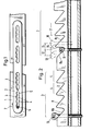
- the osteosynthesis plate 2 lying on a bone 1 with a transverse fracture in FIG. 1 contains in its sections assigned to each of the two bone fragments two elongated holes 3, each with four hole sections 4, which are each recognizable as a pair of opposing boundary arches 5 and each with one Ramp are equipped and therefore are referred to here as ramp hole sections.
- the ramps on the left in FIG. 1 are arranged falling to the right, while the ramps on the right side are arranged falling to the left, so that when the bone screw arranged at 6 in FIG. 1 is screwed in, the associated bone fragments move in the direction of the arrow 7, that is, in the compression direction. Details of this Function will now be illustrated with reference to FIG. 2, which represents the left section of the osteosynthesis plate in FIG. 1 - greatly enlarged compared to bone 1.
- the areas in which the elongated holes 3 are located are indicated in FIG. 2 by corresponding brackets.
- In the respective ramp hole sections 4 are zugeord - Neten ramps 8 as inclined planes recognizable.
- a first bone screw is inserted into the right-hand elongated hole in FIG. 2 in the end distal to the fracture in position 10.
- it slides with its screw head down the inclined plane 8a and thereby takes the underlying bone 1 with it, which thereby causes the Route 12 is moved in the direction of the arrow.
- the second bone screw is inserted over the elongated hole on the left in the drawing at its end distal to the fracture in item 13 and screwed in until it strikes the associated inclined plane 8b and thereby secures the bone 1 in the position reached against the osteosynthesis plate.
- the first screw is loosened up to item 14, in which it is located freely above the plate.
- the usable ramp length is in each case approximately equal to sections 12 or 15 or a little larger. It is the distance that the bone is displaced from the osteosynthesis plate when a screw moves from the extreme end of a ramp to the extreme other end of the same ramp.
- the spacing between two ramp hole sections is denoted by 17 in FIG. 2.
Abstract
Description
Die Erfindung bezieht sich auf eine Osteosyntheseplatte für die Druckstabilisierung von Knochenfragmenten.The invention relates to an osteosynthesis plate for the pressure stabilization of bone fragments.
In der Osteosynthese ist es bekannt, daß die Knochenheilung durch Stabilität und Druck im Knochenspalt gefördert wird. Es sind daher Spannvorrichtungen entwickelt worden, die in Verbindung mit Osteosyntheseplatten die Druckstabilisierung der Knochenfragmente ermöglichen. - Dazu gehören Osteosyntheseplatten; deren Schraubenlöcher in der Art einer schiefen Ebene geneigte LOchwände, im folgenden als Rampen bezeichnet, aufweisen, so daß beim Einschrauben einer Knochenschraube der Schraubenkopf auf der Rampe gleitet und damit eine Verschiebung der Platte im Verhältnis zu dem die Knochenschraube aufnehmenden Knochenfragment bewirkt. Der größtmögliche Kompressionsweg, der durch die Lochgeometrie und die Dicke der Platte bestimmt ist, ist dabei sehr kurz. - Größere Kompressionsstrecken lassen sich mit Hilfe einer besonderen Spannvorrichtung erreichen, die zusätzlich zur Osteosyntheseplatte angesetzt wird. Wenn diese Vorrichtung außerhalb der Knochenplatte an einem Knochenfragment festgeschraubt wird, hat sie den Nachteil einer größeren Wunde, größeren operativen Aufwands und längerer Operatiönszeit. Wenn sie im Bereich der Osteosyntheseplatte in Verbindung mit einem in dieser vorgesehenen Langloch angebracht wird (DE-OS 31 34 120), kann je nach Art der Bruchform und Lage des Langlochs eine eingeschränkte Versorgungsmöglichkeit gegeben sein.It is known in osteosynthesis that bone healing is promoted by stability and pressure in the bone gap. Clamping devices have therefore been developed which, in conjunction with osteosynthesis plates, enable the pressure stabilization of the bone fragments. - These include osteosynthesis plates; whose screw holes have inclined hole walls in the manner of an inclined plane, hereinafter referred to as ramps, so that when a bone screw is screwed in, the screw head slides on the ramp and thus a displacement of the plate in relation to the bone receiving the bone screw fragment causes. The largest possible compression path, which is determined by the hole geometry and the thickness of the plate, is very short. - Larger compression stretches can be achieved with the help of a special clamping device, which is attached to the osteosynthesis plate. When this device is screwed to a bone fragment outside the bone plate, it has the disadvantage of a larger wound, greater surgical effort and a longer operating time. If it is attached in the area of the osteosynthesis plate in connection with an elongated hole provided in it (DE-OS 31 34 120), depending on the type of fracture and the position of the elongated hole, there may be a restricted supply option.
Der Erfindung liegt die Aufgabe zugrunde, eine Osteosyntheseplatte zu schaffen, die für die Druckstabilisierung die Einfachheit und bewährte Wirksamkeit der Rampenlöcher nutzt und dennoch eine größere Kompressionsstrecke ermöglicht.The invention has for its object to provide an osteosynthesis plate that uses the simplicity and proven effectiveness of the ramp holes for pressure stabilization and still allows a larger compression distance.
Die erfindungsgemäße Lösung besteht darin, daß mehrere demselben Knochenfragment zugeordnete Langlöcher mit jeweils mehreren Rampenlochabschnitten vorgesehen sind, wobei die Teilungsabstände der demselben Langloch angehörenden Rampenlochabschnitte nicht größer sind als die Zahl der demselben Knochenfragment zugeordneten Langlöcher multipliziert mit der nutzbaren Rampenlänge. Um mit lediglich zwei Langlöchern auskommen zu können, sind die Teilungsabstände der Rampenlochabschnitte zweckmäßigerweise geringer als die doppelte nutzbare Rampenlänge.The solution according to the invention is that a plurality of elongated holes assigned to the same bone fragment are provided, each having a plurality of ramp hole sections, the spacing between the ramp hole sections belonging to the same elongated hole being no greater than the number of elongated holes assigned to the same bone fragment multiplied by the usable ramp length. In order to be able to make do with only two elongated holes, the pitch distances of the ramp hole sections are expediently less than twice the usable ramp length.
Die erfindungsgemäße Osteosyntheseplatte wird in der Weise genutzt, daß Knochenschrauben in den unterschiedlichen Langlöchern alternierend eingedreht und wieder gelöst. werden. Nachdem eine erste Knochenschraube innerhalb eines ersten Langlochs in einem darin der Fraktur nahegelegenen Rampenlochabschnitt eingedreht worden ist, wodurch ein erster Kompressionsschritt durchgeführt wurde, wird eine zweite Knochenschraube in einem anderen Langloch so angesetzt, daß sie in den Anfang einer Rampe eingreift. Danach wird die erste Schraube gelöst und durch Eindrehen der zweiten Schraube ein zweiter Kompressionsschritt durchgeführt. Wenn die Teilungsabstände der Rampenlochabschnitte geringer sind als die doppelte nutzbare Rampenlänge, hat in diesem zweiten Kompressionsschritt die erste Schraube den Beginn eines weiteren Rampenlochabschnitts erreicht, wird mit diesem in Eingriff gebracht, worauf die zweite Schraube gelöst werden kann und die erste Schraube wieder eingedreht wird, was einen dritten Kompressionsschritt ergibt usw. Wenn drei Langlöcher vorhanden sind und die nutzbare Rampenlänge einem Drittel der Teilungsabstände entspricht, werden in entsprechender Weise drei Schrauben alternierend eingedreht und gelöst.The osteosynthesis plate according to the invention is used in such a way that bone screws are alternately screwed in and loosened in the different elongated holes. will. After a first bone screw has been screwed into a ramp hole section close to the fracture within a first slot, whereby a first compression step has been carried out, a second bone screw is inserted in another slot so that it engages in the beginning of a ramp. Then the first screw is loosened and a second compression step is carried out by screwing in the second screw. If the pitch of the ramp hole sections is less than twice the usable ramp length, in this second compression step the first screw has reached the start of another ramp hole section, is brought into engagement with it, whereupon the second screw can be loosened and the first screw is screwed in again, which results in a third compression step, etc. If there are three elongated holes and the usable ramp length corresponds to a third of the spacing, three screws are alternately screwed in and loosened.
Auf diese Weise lassen sich beliebig lange Kompressionsstrecken überwinden. Dies ist insbesondere bei Osteotomien, beispielsweise im Bereich des Hüftgelenks, wichtig, weil es dabei notwendig werden kann, zur Kompression der Schnittflächen Wege von mehrere Millimetern bis in die Größenordnung von 1 cm zu überwinden.In this way, compression lengths of any length can be overcome. This is particularly important in the case of osteotomies, for example in the area of the hip joint, because it may be necessary to cover distances of several millimeters to the order of magnitude of 1 cm in order to compress the cut surfaces.
Selbstverständlich ist dieses Prinzip auch für die gegenüber der Kompression umgekehrte Bewegungsrichtung zum Zwecke der Dekompression einsetzbar. Diese Möglichkeit, bei der die Rampenanordnung in den den beiden Knochenfragmenten zugeordneten Plattenabschnitten umgekehrt ist, soll daher von dem Schutzrecht gleichfalls umfaßt sein.Of course, this principle can also be used for the direction of movement opposite to compression for the purpose of decompression. This possibility, in which the ramp arrangement in the plate sections assigned to the two bone fragments is reversed, should therefore also be covered by the property right.
Die Erfindung wird im folgenden näher unter Bezugnahme auf die Zeichnung erläutert. Darin zeigen:
- Fig. 1 eine schematische Draufsicht auf die erfindungsgemäße Platte und
- Fig. 2 in vergrößerter, schematischer Darstellung das Funktionsprinzip.
- Fig. 1 is a schematic plan view of the plate according to the invention and
- Fig. 2 in an enlarged, schematic representation of the principle of operation.
Die in Fig. 1 auf einem Knochen 1 mit einer Querfraktur liegende Osteosyntheseplatte 2 enthält in ihrer jedem der beiden Knochenfragmente zugeordneten Abschnitte zwei Langlöcher 3, die jeweils vier Lochabschnitte 4, die jeweils als ein Paar von einander gegenüberliegenden Begrenzungsbögen 5 erkennbar sind und jeweils mit einer Rampe ausgerüstet sind und deshalb hier als Rampenlochabschnitte bezeichnet werden, aufweisen. Die Rampen auf der linken Seite in Fig. 1 sind fallend nach rechts angeordnet, während die Rampen auf der rechten Seite fallend nach links angeordnet sind, so daß sich beim Eindrehen der bei 6 in Fig. 1 angeordneten Knochenschraube eine Bewegung des zugehörigen Knochenfragmente in Pfeilrichtung 7, also in Kompressionsrichtung, ergibt. Einzelheiten dieser Funktion werden nun anhand von Fig. 2 dargestellt, die den in Fig. 1 linken Abschnitt der Osteosyntheseplatte - stark vergrößert gegenüber dem Knochen 1 - darstellt. Die Bereiche, in denen sich die Langlöcher 3 befinden, sind in Fig. 2 durch entsprechende Klammern angegeben. Darin sind die den jeweiligen Rampenlochabschnitten 4 zugeord- neten Rampen 8 als schiefe Ebenen erkennbar.The
Zunächst wird eine erste Knochenschraube in dem in Fig. 2 rechten Langloch in deren der Fraktur fernen Ende eingesetzt in Position 10. Beim Eindrehen gleitet sie mit ihrem Schraubenkopf die schiefe Ebene 8a hinab und nimmt dabei den darunter liegenden Knochen 1 mit, der dadurch um die Strecke 12 in Pfeilrichtung verschoben wird. Nun wird die zweite Knochenschraube über dem in der Zeichnung linken Langloch an dessen der Fraktur fernen Ende eingesetzt in Pos. 13 und eingedreht, bis sie an der zugehörigen schiefen Ebene 8b anschlägt und dadurch den Knochen 1 in der erreichten Position gegenüber der Osteosyntheseplatte sichert. Dann wird die erste Schraube gelockert bis zur Pos. 14, in der sie sich frei über der Platte befindet. Durch das Eindrehen der zweiten Schraube verschiebt sich der Knochen um den Abschnitt 15 in Pfeilrichtung, wobei die erste Schraube aus der Position 14 in Pos. 16 wandert, in der sie sich über der Rampe 8c des nächsten Rampenlochabschnitts befindet. Sie kann nun mit dieser Rampe in Eingriff gebracht werden, worauf die zweite Schraube gelockert wird, usw. Durch das alternierende Eindrehen und Lösen der Schraube kommt es auf diese Weise zu einer beliebig langen Kompressionsstrecke.First of all, a first bone screw is inserted into the right-hand elongated hole in FIG. 2 in the end distal to the fracture in position 10. When screwed in, it slides with its screw head down the inclined plane 8a and thereby takes the
In dem dargestellten Beispiel ist die nutzbare Rampenlänge jeweils etwa gleich den Abschnitten 12 bzw. 15 oder ein wenig größer. Es handelt sich dabei um diejenige Strecke, um die der Knochen gegenüber der Osteosyntheseplatte verschoben wird, wenn eine Schraube sich vom äußersten einen Ende einer Rampe bis zum äußersten anderen Ende derselben Rampe bewegt. Der Teilungsabstand zwischen zwei Rampenlochabschnitten ist in Fig. 2 mit 17 bezeichnet.In the example shown, the usable ramp length is in each case approximately equal to
Claims (2)
Priority Applications (1)
| Application Number | Priority Date | Filing Date | Title |
|---|---|---|---|
| AT86105850T ATE40036T1 (en) | 1985-05-06 | 1986-04-28 | OSTEOSYNTHESIS PLATE FOR PRESSURE STABILIZATION. |
Applications Claiming Priority (2)
| Application Number | Priority Date | Filing Date | Title |
|---|---|---|---|
| DE8513286U | 1985-05-06 | ||
| DE8513286U DE8513286U1 (en) | 1985-05-06 | 1985-05-06 | Osteosynthesis plate for pressure stabilization |
Publications (2)
| Publication Number | Publication Date |
|---|---|
| EP0201023A1 true EP0201023A1 (en) | 1986-11-12 |
| EP0201023B1 EP0201023B1 (en) | 1989-01-18 |
Family
ID=6780723
Family Applications (1)
| Application Number | Title | Priority Date | Filing Date |
|---|---|---|---|
| EP86105850A Expired EP0201023B1 (en) | 1985-05-06 | 1986-04-28 | Osteosynthetic plate for compression stabilisation |
Country Status (4)
| Country | Link |
|---|---|
| US (1) | US4705031A (en) |
| EP (1) | EP0201023B1 (en) |
| AT (1) | ATE40036T1 (en) |
| DE (2) | DE8513286U1 (en) |
Cited By (2)
| Publication number | Priority date | Publication date | Assignee | Title |
|---|---|---|---|---|
| EP0374084A1 (en) * | 1988-11-11 | 1990-06-20 | Joachim Dr.-Med. Schmidt | Sliding hole plate for osteosynthesis |
| US9855082B2 (en) | 2009-05-12 | 2018-01-02 | DePuy Synthes Products, Inc. | Readjustable locking plate hole |
Families Citing this family (14)
| Publication number | Priority date | Publication date | Assignee | Title |
|---|---|---|---|---|
| US5015248A (en) * | 1990-06-11 | 1991-05-14 | New York Society For The Relief Of The Ruptured & Crippled, Maintaining The Hospital For Special Surgery | Bone fracture fixation device |
| US5611354A (en) * | 1992-11-12 | 1997-03-18 | Alleyne; Neville | Cardiac protection device |
| EP1149560A3 (en) * | 1992-11-12 | 2002-03-06 | ALLEYNE, Neville | Spinal protection device |
| US5951557A (en) * | 1997-12-30 | 1999-09-14 | Luter; Dennis W. | Bone plate |
| US7717945B2 (en) | 2002-07-22 | 2010-05-18 | Acumed Llc | Orthopedic systems |
| AUPR546601A0 (en) * | 2001-06-05 | 2001-06-28 | Australian Surgical Design And Manufacture Pty Limited | High tibial osteotomy device |
| AU2003268480A1 (en) * | 2002-09-06 | 2004-03-29 | Neville D. Alleyne | Seal for posterior lateral vertebral disk cavity |
| EP1643923A4 (en) * | 2003-06-20 | 2010-10-06 | Acumed Llc | Bone plates with intraoperatively tapped apertures |
| US20050177155A1 (en) * | 2003-10-28 | 2005-08-11 | Neville Alleyne | Anterior adhesion resistant barrier for spine |
| US20070198016A1 (en) * | 2006-02-21 | 2007-08-23 | Osteomed, L.P. | Compression stabilizing spacers |
| EP2273936A4 (en) * | 2008-04-04 | 2012-09-05 | Skeletal Dynamics Llc | Compression/distraction osteotomy system, plate, method, drill guide and saw guide |
| US20100057133A1 (en) * | 2008-08-26 | 2010-03-04 | Simon William H | Tibia-talus-calcaneus (T-T-C) locking plate |
| US10869702B2 (en) | 2017-05-12 | 2020-12-22 | Nextremity Solutions, Inc. | Compression force magnifier |
| US11202664B2 (en) | 2018-12-17 | 2021-12-21 | Nextremity Solutions, Inc. | Compression force magnifier |
Citations (4)
| Publication number | Priority date | Publication date | Assignee | Title |
|---|---|---|---|---|
| US3528085A (en) * | 1968-03-22 | 1970-09-08 | Walker Reynolds Jr | Bone compression plate |
| US3547114A (en) * | 1967-07-07 | 1970-12-15 | Edward J Haboush | Compensating plate means for bone fractures |
| US3604414A (en) * | 1968-08-29 | 1971-09-14 | Nicomedes Borges | Bone setting device |
| DE8309326U1 (en) * | 1983-03-29 | 1984-10-25 | Waldemar Link (Gmbh & Co), 2000 Hamburg | Spinal fusion plate |
Family Cites Families (4)
| Publication number | Priority date | Publication date | Assignee | Title |
|---|---|---|---|---|
| FR1505513A (en) * | 1966-11-02 | 1967-12-15 | Benoist & Girard Reunis | Osteosynthesis plate |
| GB1571713A (en) * | 1976-04-21 | 1980-07-16 | Gil J L | Apparatus for use in the treatment of bone fractures |
| ZA80327B (en) * | 1979-08-23 | 1981-09-30 | U Mennen | Internal fixation device for bone fractures |
| IT1132843B (en) * | 1980-09-15 | 1986-07-09 | Cise Spa | PLATE FOR JOINTS OF SEPARATE BONE PORTIONS FROM FRACTURE |
-
1985
- 1985-05-06 DE DE8513286U patent/DE8513286U1/en not_active Expired
-
1986
- 1986-04-28 EP EP86105850A patent/EP0201023B1/en not_active Expired
- 1986-04-28 DE DE8686105850T patent/DE3661793D1/en not_active Expired
- 1986-04-28 AT AT86105850T patent/ATE40036T1/en not_active IP Right Cessation
- 1986-05-05 US US06/859,650 patent/US4705031A/en not_active Expired - Lifetime
Patent Citations (4)
| Publication number | Priority date | Publication date | Assignee | Title |
|---|---|---|---|---|
| US3547114A (en) * | 1967-07-07 | 1970-12-15 | Edward J Haboush | Compensating plate means for bone fractures |
| US3528085A (en) * | 1968-03-22 | 1970-09-08 | Walker Reynolds Jr | Bone compression plate |
| US3604414A (en) * | 1968-08-29 | 1971-09-14 | Nicomedes Borges | Bone setting device |
| DE8309326U1 (en) * | 1983-03-29 | 1984-10-25 | Waldemar Link (Gmbh & Co), 2000 Hamburg | Spinal fusion plate |
Cited By (4)
| Publication number | Priority date | Publication date | Assignee | Title |
|---|---|---|---|---|
| EP0374084A1 (en) * | 1988-11-11 | 1990-06-20 | Joachim Dr.-Med. Schmidt | Sliding hole plate for osteosynthesis |
| US4957496A (en) * | 1988-11-11 | 1990-09-18 | Mecron Medizinische Produkte Gmbh | Slotted slide plate assembly for osteosynthesis |
| US9855082B2 (en) | 2009-05-12 | 2018-01-02 | DePuy Synthes Products, Inc. | Readjustable locking plate hole |
| US10799275B2 (en) | 2009-05-12 | 2020-10-13 | DePuy Synthes Products, Inc. | Readjustable locking plate hole |
Also Published As
| Publication number | Publication date |
|---|---|
| EP0201023B1 (en) | 1989-01-18 |
| ATE40036T1 (en) | 1989-02-15 |
| US4705031A (en) | 1987-11-10 |
| DE8513286U1 (en) | 1986-09-04 |
| DE3661793D1 (en) | 1989-02-23 |
Similar Documents
| Publication | Publication Date | Title |
|---|---|---|
| EP0201023B1 (en) | Osteosynthetic plate for compression stabilisation | |
| EP0374084B1 (en) | Sliding hole plate for osteosynthesis | |
| DE3713351C2 (en) | ||
| EP0920284B1 (en) | Calcaneal bone plate | |
| DE8519854U1 (en) | Self-tightening straight bone plate | |
| DE2712696C3 (en) | Jaw expansion screw | |
| DE1566153B1 (en) | Osteosynthetic pressure plate | |
| EP0410309A1 (en) | Stabilising element for bones | |
| WO1997013255A2 (en) | Contour collimator for radiotherapy | |
| DE2413219A1 (en) | BOARD FOR ELECTRICAL CONNECTIONS | |
| EP0154813A1 (en) | Clamping device for machine tools | |
| DD218274A5 (en) | OUTSIDE ORTHOPEDIC MOUNTING DEVICE | |
| AT411094B (en) | CONNECTOR | |
| EP0659644A1 (en) | Apparatus for forming groups of cigarettes | |
| DE60202051T2 (en) | SENSOR CARRIER | |
| EP0423474A1 (en) | Device for the releasable fastening of two profiled rods | |
| DE2360260A1 (en) | TOUCH PROTECTION FOR BUSBARS IN ELECTRICAL DISTRIBUTION SYSTEMS AND THE LIKE | |
| DE3038121C2 (en) | Fastening device for a clearing strip | |
| DE3809037C2 (en) | ||
| DE102018007133B4 (en) | Strip-shaped component carrier | |
| DE3433105C2 (en) | ||
| DE3139575C2 (en) | ||
| EP0724112A1 (en) | Profiled bar and use thereof | |
| DE2802090A1 (en) | COMPRESSION / DISTRACTION DEVICE FOR OSTEOSYNTHESIS | |
| DE2649149A1 (en) | Stop for fastening element in curtain tracks - has threaded pin and nut with wider collar to adapt to any sized curtain track |
Legal Events
| Date | Code | Title | Description |
|---|---|---|---|
| PUAI | Public reference made under article 153(3) epc to a published international application that has entered the european phase |
Free format text: ORIGINAL CODE: 0009012 |
|
| AK | Designated contracting states |
Kind code of ref document: A1 Designated state(s): AT BE CH DE FR GB IT LI NL SE |
|
| 17P | Request for examination filed |
Effective date: 19870205 |
|
| 17Q | First examination report despatched |
Effective date: 19880510 |
|
| GRAA | (expected) grant |
Free format text: ORIGINAL CODE: 0009210 |
|
| AK | Designated contracting states |
Kind code of ref document: B1 Designated state(s): AT BE CH DE FR GB IT LI NL SE |
|
| PG25 | Lapsed in a contracting state [announced via postgrant information from national office to epo] |
Ref country code: SE Effective date: 19890118 |
|
| REF | Corresponds to: |
Ref document number: 40036 Country of ref document: AT Date of ref document: 19890215 Kind code of ref document: T |
|
| REF | Corresponds to: |
Ref document number: 3661793 Country of ref document: DE Date of ref document: 19890223 |
|
| ITF | It: translation for a ep patent filed |
Owner name: UFFICIO TECNICO ING. A. MANNUCCI |
|
| GBT | Gb: translation of ep patent filed (gb section 77(6)(a)/1977) | ||
| ET | Fr: translation filed | ||
| PLBE | No opposition filed within time limit |
Free format text: ORIGINAL CODE: 0009261 |
|
| STAA | Information on the status of an ep patent application or granted ep patent |
Free format text: STATUS: NO OPPOSITION FILED WITHIN TIME LIMIT |
|
| 26N | No opposition filed | ||
| ITTA | It: last paid annual fee | ||
| PGFP | Annual fee paid to national office [announced via postgrant information from national office to epo] |
Ref country code: NL Payment date: 19920430 Year of fee payment: 7 |
|
| PGFP | Annual fee paid to national office [announced via postgrant information from national office to epo] |
Ref country code: BE Payment date: 19920604 Year of fee payment: 7 |
|
| PG25 | Lapsed in a contracting state [announced via postgrant information from national office to epo] |
Ref country code: BE Effective date: 19930430 |
|
| PGFP | Annual fee paid to national office [announced via postgrant information from national office to epo] |
Ref country code: GB Payment date: 19931015 Year of fee payment: 8 |
|
| PGFP | Annual fee paid to national office [announced via postgrant information from national office to epo] |
Ref country code: FR Payment date: 19931029 Year of fee payment: 8 |
|
| BERE | Be: lapsed |
Owner name: WOLTER DIETMAR Effective date: 19930430 |
|
| PG25 | Lapsed in a contracting state [announced via postgrant information from national office to epo] |
Ref country code: NL Effective date: 19931101 |
|
| NLV4 | Nl: lapsed or anulled due to non-payment of the annual fee | ||
| PG25 | Lapsed in a contracting state [announced via postgrant information from national office to epo] |
Ref country code: GB Effective date: 19940428 |
|
| PG25 | Lapsed in a contracting state [announced via postgrant information from national office to epo] |
Ref country code: FR Effective date: 19941229 |
|
| GBPC | Gb: european patent ceased through non-payment of renewal fee |
Effective date: 19940428 |
|
| REG | Reference to a national code |
Ref country code: FR Ref legal event code: ST |
|
| PGFP | Annual fee paid to national office [announced via postgrant information from national office to epo] |
Ref country code: AT Payment date: 19980623 Year of fee payment: 13 |
|
| PG25 | Lapsed in a contracting state [announced via postgrant information from national office to epo] |
Ref country code: AT Free format text: LAPSE BECAUSE OF NON-PAYMENT OF DUE FEES Effective date: 19990428 |
|
| PGFP | Annual fee paid to national office [announced via postgrant information from national office to epo] |
Ref country code: CH Payment date: 20000523 Year of fee payment: 15 |
|
| PG25 | Lapsed in a contracting state [announced via postgrant information from national office to epo] |
Ref country code: LI Free format text: LAPSE BECAUSE OF NON-PAYMENT OF DUE FEES Effective date: 20010527 Ref country code: CH Free format text: LAPSE BECAUSE OF NON-PAYMENT OF DUE FEES Effective date: 20010527 |
|
| PGFP | Annual fee paid to national office [announced via postgrant information from national office to epo] |
Ref country code: DE Payment date: 20010619 Year of fee payment: 16 |
|
| REG | Reference to a national code |
Ref country code: CH Ref legal event code: PL |
|
| PG25 | Lapsed in a contracting state [announced via postgrant information from national office to epo] |
Ref country code: DE Free format text: LAPSE BECAUSE OF NON-PAYMENT OF DUE FEES Effective date: 20021101 |
|
| PG25 | Lapsed in a contracting state [announced via postgrant information from national office to epo] |
Ref country code: IT Free format text: LAPSE BECAUSE OF NON-PAYMENT OF DUE FEES;WARNING: LAPSES OF ITALIAN PATENTS WITH EFFECTIVE DATE BEFORE 2007 MAY HAVE OCCURRED AT ANY TIME BEFORE 2007. THE CORRECT EFFECTIVE DATE MAY BE DIFFERENT FROM THE ONE RECORDED. Effective date: 20050428 |