EP0200356A2 - Electrical jumper - Google Patents
Electrical jumper Download PDFInfo
- Publication number
- EP0200356A2 EP0200356A2 EP86302234A EP86302234A EP0200356A2 EP 0200356 A2 EP0200356 A2 EP 0200356A2 EP 86302234 A EP86302234 A EP 86302234A EP 86302234 A EP86302234 A EP 86302234A EP 0200356 A2 EP0200356 A2 EP 0200356A2
- Authority
- EP
- European Patent Office
- Prior art keywords
- apertures
- pair
- entry
- long side
- terminal member
- Prior art date
- Legal status (The legal status is an assumption and is not a legal conclusion. Google has not performed a legal analysis and makes no representation as to the accuracy of the status listed.)
- Granted
Links
Images

Classifications
-
- H—ELECTRICITY
- H01—ELECTRIC ELEMENTS
- H01R—ELECTRICALLY-CONDUCTIVE CONNECTIONS; STRUCTURAL ASSOCIATIONS OF A PLURALITY OF MUTUALLY-INSULATED ELECTRICAL CONNECTING ELEMENTS; COUPLING DEVICES; CURRENT COLLECTORS
- H01R9/00—Structural associations of a plurality of mutually-insulated electrical connecting elements, e.g. terminal strips or terminal blocks; Terminals or binding posts mounted upon a base or in a case; Bases therefor
-
- H—ELECTRICITY
- H01—ELECTRIC ELEMENTS
- H01R—ELECTRICALLY-CONDUCTIVE CONNECTIONS; STRUCTURAL ASSOCIATIONS OF A PLURALITY OF MUTUALLY-INSULATED ELECTRICAL CONNECTING ELEMENTS; COUPLING DEVICES; CURRENT COLLECTORS
- H01R31/00—Coupling parts supported only by co-operation with counterpart
- H01R31/08—Short-circuiting members for bridging contacts in a counterpart
-
- H—ELECTRICITY
- H01—ELECTRIC ELEMENTS
- H01R—ELECTRICALLY-CONDUCTIVE CONNECTIONS; STRUCTURAL ASSOCIATIONS OF A PLURALITY OF MUTUALLY-INSULATED ELECTRICAL CONNECTING ELEMENTS; COUPLING DEVICES; CURRENT COLLECTORS
- H01R11/00—Individual connecting elements providing two or more spaced connecting locations for conductive members which are, or may be, thereby interconnected, e.g. end pieces for wires or cables supported by the wire or cable and having means for facilitating electrical connection to some other wire, terminal, or conductive member, blocks of binding posts
- H01R11/01—Individual connecting elements providing two or more spaced connecting locations for conductive members which are, or may be, thereby interconnected, e.g. end pieces for wires or cables supported by the wire or cable and having means for facilitating electrical connection to some other wire, terminal, or conductive member, blocks of binding posts characterised by the form or arrangement of the conductive interconnection between the connecting locations
Definitions
- This invention relates to electrical connectors, and particularly to an electrical jumper for electrically connecting two or more adjacent pins which extend from electronic devices.
- Printed circuit boards are typically provided with a row or array of pins (a "pin field") to facilitate making connections between the electronic components on the board and external devices including other printed circuit boards.
- Electronic equipment including digital computers, may also be provided with such pin fields for connecting the equipment to peripheral devices or data communication lines.
- a printed circuit board is capable of several uses, the devices which can be connected to its pin field may vary. This is almost certainly the case with a pin field of a general purpose device such as a digital computer. For some applications, it may be necessary to "jump", or electrically interconnect, two or more pins in the pin field. The jumped'pins may or may not have further connections made to them.
- jumpers which can interconnect two or more pins in a pin field.
- the jumpers are generally rectangular and of such dimensions that there is sufficient space to connect additional jumpers on adjacent pins.
- the jumpers have an entry end with apertures for the entry of the pins, and are generally shorter than the pins so that the pins protrude from the opposite, exit end of the jumper to allow additional connections to be made to them. Because of their small dimensions, these jumpers are sometimes called "low profile" jumpers.
- Such jumpers have a housing made of a nonconductive, dielectric material, having electrically interconnected terminals for receiving the pins to be jumped. It is known to provide electrically interconnected terminals by forming the entire terminal member from one piece of conductive material, by stamping or otherwise.
- a conductive material commonly used is a metal, such as hard phosphor bronze, plated with nickel, then overplated with gold or a tin/lead alloy.
- the terminal member has four arms, two for engaging each pin. Each pair of arms engages its respective pin from two sides. Each arm is provided with a dimple for better contact with its respective pin.
- the arms extend from a central spine, which is received in a slot in the housing, across to the sides of the housing. The free ends of the arms are supported in slots in the sides of the housing.
- the terminal members of the known jumper are plated after they are formed.
- Such post-plating is a more diffi - cult and expensive step than pre-plating.
- Jumpers of the types generally described above can be provided in multiple units which allow discrete pairs of pins to be electrically connected by a number of electrically isolated terminal members in a common housing.
- jumpers can be provided which interconnect a multiplicity of pins in a bus bar configuration.
- a general object of the present invention u s to provide an improved form of electrical connector or jumper.
- a jumper for electrically connecting terminal pins including a housing of dielectric material having a solid rectangular shape, an entry end having at least one pair of apertures for receiving said pins, an open exit end opposite said entry end, first and second long side walls parallel to each other and perpendicular to said entry and exit ends, first and second short side walls parallel to each other and perpendicular to said entry and exit ends and to said long side walls, a latch associated with each said pair of apertures comprising a ramp having a latch width and extending from said first long side wall toward said entry end and toward said second long side wall between the two apertures of said pair of apertures, and further having a lip adjacent said entry end and said second long side wall, said lip being a first preselected distance from said second long side wall and a second preselected distance from said entry end and having a lip height, the sum of said lip height and said first preselected distance defining a third preselected distance, and a respective rail member extending along said second long side wall from said
- a terminal member associated with each said pair of apertures comprising a pair of twin-beam terminals of electrically conductive material for alignment with said apertures, each of said terminals having an entry end and an exit end, the entry and exit ends of each said terminals connected to the entry and exit ends, respectively, of the other of said terminals by a respective electrically conductive cross-piece, each of said cross-pieces having a thickness greater than the difference between said first preselected distance and said fourth preselected distance, no greater than the difference between said third preselected distance and said fourth preselected distance, and no greater than said first preselected distance, and a width approximately equal to and no greater than said second preselected distance.
- the terminal member has a rectangular opening formed by said pair of terminals and said cross-pieces.
- the opening has a width no less than said latch width.
- the terminal member further has four tabs extending laterally outwardly from the corners thereof, the tabs being formed by extensions of the cross-pieces.
- the terminal member is supported in the housing on the rail members, spaced from the second long side wall, by the tabs.
- the lip of the latch engages the cross-piece that connects the entry ends of the terminals, with the latch extending into the rectangular opening, thereby retaining the terminal member in the housing.
- Jumpers constructed in accordance with the invention can be assembled automatically at high speed can have a low profile and can utilise a terminal member of pre-plated metal which is relatively simple to manufacture.
- a jumper in accordance with the invention comprises a carton-like rectangular housing with at least, two apertures for receiving separate electrical terminal pins, one-piece pre-plated terminal means disposed in the housing and composed of respective interconnected twin-beam terminals with pin-receiving entry zones aligned with the apertures.
- the terminal means is introduced into the housing opposite the apertures and guided with guide rails onto latch means.
- the latch means locks the terminal means in the housing as a snap-fitting.
- the jumper of this invention can be made as a single jumper, as multiple, physically connected but electrically separate jumpers, or as multiple, physically and electrically connected jumpers.
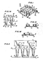
- FIGS. 1-6A The preferred embodiment of a single jumper according to this invention is shown in FIGS. 1-6A.
- the jumper includes the terminal member shown in FIGS. 1-2 and the housing shown in FIGS. 3-6A.
- the terminal member 10 includes two terminals 11, 12 of the twin-beam type.
- Each terminal 11, 12 includes two strips, or "beams", 13, 14 and 15, 16 respectively, connected at their proximal ends 17 to the terminal and held in fixed, spaced-apart relationship.
- the beams 13, 14 and 15, 16 converge as they extend along their respective terminals 11, 12 reaching a point of closest proximity adjacent their distal ends 18 and then flaring slightly at ends 18.
- Ends 18 are the entry ends of terminals 11, 12, through which contact pins (not shown) are inserted into the terminals.
- Ends 17 are the exit ends of terminals 11, 12 through which the contact pins protrude if they are longer than terminals 11, 12.
- the convergence of the beams 13, 14 and 15, 16 and the resiliency of the metal from which they are made give rise to positive frictional and electrical contact between each terminal 11, 12 and the pin inserted therein.
- Terminals 11, 12 of terminal member 10 are interconnected by entry end cross-piece 19 and exit end cross-piece 101.
- Terminals 11, 12 and cross-pieces 19, 101 together form rectangular opening 102 in terminal member 10.
- Entry end cross-piece 19 is extended beyond terminals 11, 12 to form tabs 103, 104.
- Exit end cross-piece 101 is similarly extended to form tabs 105, 106.
- FIG. 2 shows a strip 20 of terminal members 10.
- Terminal members 10 are manufactured as a unit, attached to carrier 21, by stamping from a single piece of electrically conductive metal.
- Strip 20 is fed into the machine which assembles terminal members 10 into the housings to be described below.
- the individual terminal members 10 are broken off strip 20 as they are assembled by severing score lines 22, 23, 24. Holes 25 in carrier 21 are provided for proper indexing of strip 20 during assembly.
- Terminal members 10 are preferably plated for improved conductivity.
- a preferred composition for terminal members 10 is a substrate of hard phosphor bronze with a plating of nickel and an overplating of substantially pure gold or an overplating of a 93/7 tin/lead alloy.
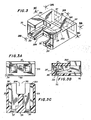
- Single jumper housing 30 is made of a dielectric material, preferably a plastic.
- a particularly preferred plastic is glass-filled polyester.
- Housing 30 has first and second long side walls 31, 32, first and second short side walls 33, 34, an entry end 35, and an open exit end 36. Entry end 35 has two apertures 37 for receiving contact pins. Apertures 37 are aligned with terminals 11, 12.
- a commonly used pin spacing in the type of electronc devices for use with which this invention is intended is 0.100 inch (2.54 mm), and therefore the preferred separation distance for apertures 37 (and for terminals 11, 12) is 0.100 inch (2.54 mm).
- other spacings can be provided and, in fact, the jumper of the invention can be used for applications that do not involve printed circuit boards.
- Latch 38 Projecting into housing 30 from first long side wall 31, and centered between the two apertures 37, is a latch 38 for retaining terminal member 10 in housing 30.
- Latch 38 includes a ramp 39 extending from first long side wall 31 toward second long side wall 32 and toward entry end 35. At the end of ramp 39 is a lip 300. Latch 38 cooperates with rail members 301, which extend along second long side wall 32 from entry end 35 to exit end 36 of housing 30 on either side of the pair of apertures 37, as explained below.
- FIGS. 4-6A show the sequence of events in inserting terminal member 10 into housing 30.
- terminal member 10 has been inserted into exit end 36 of housing 30, with tabs 103, 104 riding on rails 301. Entry end cross-piece 19 has not yet reached ramp 39.
- cross-piece 19 has reached ramp 39 and has begun to bow (exaggerated in FIG. 5A) into the space between ramp 39 and second long side wall 32.
- Cross-piece 19 is free to bow because it is held away from second long side wall 32 by tabs 103, 104 riding on rails 301.
- cross-piece 19 has cleared lip 300 of ramp 39 and has snapped back to its normal configuration.
- Tabs 105 and 106 are now also riding on rails 301.
- lip 300 engages cross-piece 19 to prevent the withdrawal of terminal member 10 from housing 30.
- the body of terminal member 10 could be made to extend laterally far enough to ride rails 301. However, that would increase both the frictional contact between terminal member 10 and rails 301, and the amount of material needed to fabricate terminal member 10.
- ramp 39 can be no wider than opening 102 in terminal member 10 so that it can fit between terminals 11, 12.
- lip 300 can be no closer to entry end 35 of housing 30 than the width of cross-piece 19 so that cross-piece 19 can fit into the position shown in FIG. 6.
- the tip of lip 300 can be no closer to second long side wall 32 than the thickness of cross-piece 19, so that cross-piece 19 can fit between lip 300 and second long side wall 32 as shown in Fig. 5A.
- the difference between the distance from lip 300 to second long side wall 32 and the distance that rail members 301 project from second long side wall 32 must be less than the thickness of cross-piece 19, otherwise cross-piece 19 will not be retained by lip 300.
- the distance between the surfaces of rail members 301 and the plane of surface 302 (the distance between the tip of lip 300 and surface 302 defining the "lip height" of lip 300) must be at least the thickness of cross-piece 19, so that cross-piece 19 can fit into the position shown in FIG. 6A. However, the distance can be greater, as it is in FIG. 6A, allowing terminal number 10 to have a small degree of "float" within the housing.
- housing 30 is provided with raised portion 303 on the exterior of first long side wall 31 which provides a gripping surface for a jumper removal tool.
- cutouts 304 are provided in long side walls 31, 32 to expose exit end cross-piece 101 for gripping by a jumper removal tool.
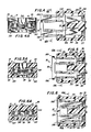
- FIG. 7 shows the exterior of the entry end of two different types 80, 81 of multiple jumpers, the cross sections of which are shown in FIGS. 8A and 8B, respectively.
- Both types can have any even multiple of apertures 37, each pair of apertures separated from adjacent pairs of apertures by partitions 70, or, in the case of a pair of apertures at the end of the jumper, separated on one side from an adjacent pair by a partition 70, and bounded on the other side by a short side wall 71.
- a latch 38 extends from first long side wall 72 between each pair of apertures 37, and rail members 301 project from second long side wall 73 adjacent short side walls 71 or partitions 70. Latches 38 and rail members 301 cooperate in the same manner as in the single jumper of FIGS. 1-6A to retain a terminal member associated with each pair of apertures within the jumper.
- Multiple jumper 80 is essentially a plurality of the single jumpers shown in FIGS. 1-6A arranged with their short sides adjacent one another.
- One terminal member 10 is associated with each pair of apertures 37, and the separate terminal members are electrically isolated from one another.
- Multiple jumper 81 is similar to jumper 80, but the partitions 70 do not extend all the way to the exit end of the jumper.
- the ends of partitions 70 in jumper 81 are spaced from the exit end by a distance equal to the width of exit end cross-piece 101 of terminal member 10.
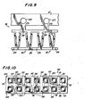
- a strip 90 of the terminal members 91 used in jumper 81 is shown in FIG. 9. It is identical to strip 20 of terminal members 10, except that score lines 23 are missing.
- exit end cross-pieces 101 form a continuous bar electrically interconnecting the terminal members 91.
- the continuous bar fits into the gaps between the ends of partitions 70 and the exit end of jumper 81.
- Jumper 81 is therefore a bus bar configuration, used to electrically interconnect many pins in one row.
- FIG. 10 shows the exterior of the entry end of another type of multiple jumper 100.
- Jumper 100 is essentially a plurality of the jumpers of FIGS. 1-6A with their long sides adjacent one another. Where the partitions 70 in jumpers 80, 81 replaced short side walls 33, 34, partitions 110 in jumper 100 replace long side walls 31, 32. Latches 38 extend from either first short side wall 111 or a partition 110 toward another partition 110 or second short side wall 113. Rails 301 extend from entry end to exit end along partitions 110 and second short side wall 113 where they meet long side walls 112. Each terminal member 10 of jumper 100 is electrically isolated from the other terminal members 10.
Abstract
Description
- This invention relates to electrical connectors, and particularly to an electrical jumper for electrically connecting two or more adjacent pins which extend from electronic devices.
- Printed circuit boards are typically provided with a row or array of pins (a "pin field") to facilitate making connections between the electronic components on the board and external devices including other printed circuit boards. Electronic equipment, including digital computers, may also be provided with such pin fields for connecting the equipment to peripheral devices or data communication lines.
- If a printed circuit board is capable of several uses, the devices which can be connected to its pin field may vary. This is almost certainly the case with a pin field of a general purpose device such as a digital computer. For some applications, it may be necessary to "jump", or electrically interconnect, two or more pins in the pin field. The jumped'pins may or may not have further connections made to them.
- It is therefore known to provide jumpers which can interconnect two or more pins in a pin field. The jumpers are generally rectangular and of such dimensions that there is sufficient space to connect additional jumpers on adjacent pins. The jumpers have an entry end with apertures for the entry of the pins, and are generally shorter than the pins so that the pins protrude from the opposite, exit end of the jumper to allow additional connections to be made to them. Because of their small dimensions, these jumpers are sometimes called "low profile" jumpers.
- Such jumpers have a housing made of a nonconductive, dielectric material, having electrically interconnected terminals for receiving the pins to be jumped. It is known to provide electrically interconnected terminals by forming the entire terminal member from one piece of conductive material, by stamping or otherwise. A conductive material commonly used is a metal, such as hard phosphor bronze, plated with nickel, then overplated with gold or a tin/lead alloy.
- In one particular known type of jumper for interconnecting two pins, the terminal member has four arms, two for engaging each pin. Each pair of arms engages its respective pin from two sides. Each arm is provided with a dimple for better contact with its respective pin. The arms extend from a central spine, which is received in a slot in the housing, across to the sides of the housing. The free ends of the arms are supported in slots in the sides of the housing.
- This known type of jumper functions well, but is not easily assembled automatically at high speeds. The free ends of the arms of the terminal member are sometimes bent out of place before the terminal member is inserted into the housing, so that they do not align properly with the slots intended to receive them. Alternatively, the arms may bend in the slots if accumulated tolerances are such that a maximum width arm is mated to a minimum width slot. As a result, the arms bend instead of seating properly in the slots. Such a jumper must then be discarded. Therefore, this type of jumper is assembled by hand.
- In addition, when forming the dimples in the arms of the known jumper, if the metal which is used for the terminal member has been plated before the dimples are formed ("pre-plated"), there is a tendency for the base metal to break through the plating when the dimple is formed. Therefore, the terminal members of the known jumper are plated after they are formed. Such post-plating is a more diffi- cult and expensive step than pre-plating.
- Jumpers of the types generally described above can be provided in multiple units which allow discrete pairs of pins to be electrically connected by a number of electrically isolated terminal members in a common housing. In addition, jumpers can be provided which interconnect a multiplicity of pins in a bus bar configuration.
- - A general object of the present invention u s to provide an improved form of electrical connector or jumper.
- In accordance with this invention, a jumper for electrically connecting terminal pins is provided including a housing of dielectric material having a solid rectangular shape, an entry end having at least one pair of apertures for receiving said pins, an open exit end opposite said entry end, first and second long side walls parallel to each other and perpendicular to said entry and exit ends, first and second short side walls parallel to each other and perpendicular to said entry and exit ends and to said long side walls, a latch associated with each said pair of apertures comprising a ramp having a latch width and extending from said first long side wall toward said entry end and toward said second long side wall between the two apertures of said pair of apertures, and further having a lip adjacent said entry end and said second long side wall, said lip being a first preselected distance from said second long side wall and a second preselected distance from said entry end and having a lip height, the sum of said lip height and said first preselected distance defining a third preselected distance, and a respective rail member extending along said second long side wall from said entry and to said exit end on either side of each said pair of apertures, each of said rail members projecting a fourth preselected distance from said second long side wall. In the housing is a terminal member associated with each said pair of apertures comprising a pair of twin-beam terminals of electrically conductive material for alignment with said apertures, each of said terminals having an entry end and an exit end, the entry and exit ends of each said terminals connected to the entry and exit ends, respectively, of the other of said terminals by a respective electrically conductive cross-piece, each of said cross-pieces having a thickness greater than the difference between said first preselected distance and said fourth preselected distance, no greater than the difference between said third preselected distance and said fourth preselected distance, and no greater than said first preselected distance, and a width approximately equal to and no greater than said second preselected distance. The terminal member has a rectangular opening formed by said pair of terminals and said cross-pieces. The opening has a width no less than said latch width. The terminal member further has four tabs extending laterally outwardly from the corners thereof, the tabs being formed by extensions of the cross-pieces. The terminal member is supported in the housing on the rail members, spaced from the second long side wall, by the tabs. The lip of the latch engages the cross-piece that connects the entry ends of the terminals, with the latch extending into the rectangular opening, thereby retaining the terminal member in the housing.
- Jumpers constructed in accordance with the invention can be assembled automatically at high speed can have a low profile and can utilise a terminal member of pre-plated metal which is relatively simple to manufacture.
- A jumper in accordance with the invention comprises a carton-like rectangular housing with at least, two apertures for receiving separate electrical terminal pins, one-piece pre-plated terminal means disposed in the housing and composed of respective interconnected twin-beam terminals with pin-receiving entry zones aligned with the apertures. During assembly the terminal means is introduced into the housing opposite the apertures and guided with guide rails onto latch means. The latch means locks the terminal means in the housing as a snap-fitting.
- The invention may be understood more readily and other features and advantages of the invention may become apparent upon consideration of the following description.
- Embodiments of the invention will now be described, by way of examples only with reference to the accompanying drawings in which like reference characters refer to like parts throughout, and in which:
- FIG. 1 is a perspective view of a terminal member of an electrical connector according to the invention;
- FIG. lA is a plan view of the terminal member of FIG. 1, the view being taken from line lA-lA of FIG. 1;
- FIG 1B is a side elevational view of the terminal member of FIG. 1, the view being taken from
line 1B-1B of FIG. lA; - FIG 1C is an end view of the terminal member of FIG. 1, the view being taken from
line 1C-1C of FIG. lA; - FIG. 2 is a plan view of a number of terminal members attached to a carrier strip;
- FIG. 3 is a perspective view of a housing of an electrical connector according to the invention;
- FIG 3A is an entry end elevational view of the housing FIG. 3 the view being taken from line 3A-3A of FIG. 3;
- FIG. 3B is a cross-sectional view of the housing of FIG. 3, the view being taken from
line 3B-3B of FIG. 3; - FIG. 3C is a cross-sectional view of the housing of FIG. 3, the view being taken from
line 3C-3C of FIG. 3; - FIGS. 4, 5 and 6 are cross-sectional views corresponding to FIG. 3C showing successive steps in the insertion of the terminal member of FIG. 1 into the housing of FIG. 3;
- FIGS. 4A, 5A and 6A are cross-sectional views of FIGS. 4, 5 and 6, respectively the views being taken from
lines 4A-4A, 5A-5A and 6A-6A, respectively; - FIG. 7 is an entry end elevational view of another housing of an electrical connector according to the invention;
- FIG. 8A is a cross-sectional view of one form of interior arrangement of the housing of FIG. 7, the view being taken along line 8-8 of FIG. 7;
- FIG. 8B is a cross-sectional view of another form of interior arrangement of the housing of FIG. 7 the view being taken along line 8-8 of FIG. 7;
- FIG. 9 is a plan view of a strip of terminal members for use with the housing of FIG. 8B; and
- FIG. 10 is an entry end elevational view of a further embodiment of a housing for an electrical connector according to the invention.
- The jumper of this invention can be made as a single jumper, as multiple, physically connected but electrically separate jumpers, or as multiple, physically and electrically connected jumpers.
- The preferred embodiment of a single jumper according to this invention is shown in FIGS. 1-6A. The jumper includes the terminal member shown in FIGS. 1-2 and the housing shown in FIGS. 3-6A.
- The
terminal member 10 includes twoterminals beams respective terminals distal ends 18 and then flaring slightly at ends 18. - Ends 18 are the entry ends of
terminals terminals terminals beams -
Terminals terminal member 10 are interconnected byentry end cross-piece 19 andexit end cross-piece 101.Terminals cross-pieces rectangular opening 102 interminal member 10.Entry end cross-piece 19 is extended beyondterminals tabs Exit end cross-piece 101 is similarly extended to formtabs - FIG. 2 shows a
strip 20 ofterminal members 10.Terminal members 10 are manufactured as a unit, attached tocarrier 21, by stamping from a single piece of electrically conductive metal.Strip 20 is fed into the machine which assemblesterminal members 10 into the housings to be described below. Theindividual terminal members 10 are broken offstrip 20 as they are assembled by severingscore lines Holes 25 incarrier 21 are provided for proper indexing ofstrip 20 during assembly. -
Terminal members 10 are preferably plated for improved conductivity. A preferred composition forterminal members 10 is a substrate of hard phosphor bronze with a plating of nickel and an overplating of substantially pure gold or an overplating of a 93/7 tin/lead alloy. -
Single jumper housing 30 is made of a dielectric material, preferably a plastic. A particularly preferred plastic is glass-filled polyester.Housing 30 has first and secondlong side walls short side walls entry end 35, and anopen exit end 36.Entry end 35 has twoapertures 37 for receiving contact pins.Apertures 37 are aligned withterminals terminals 11, 12) is 0.100 inch (2.54 mm). However, other spacings can be provided and, in fact, the jumper of the invention can be used for applications that do not involve printed circuit boards. - Projecting into
housing 30 from firstlong side wall 31, and centered between the twoapertures 37, is alatch 38 for retainingterminal member 10 inhousing 30.Latch 38 includes aramp 39 extending from firstlong side wall 31 toward secondlong side wall 32 and towardentry end 35. At the end oframp 39 is alip 300.Latch 38 cooperates withrail members 301, which extend along secondlong side wall 32 fromentry end 35 to exitend 36 ofhousing 30 on either side of the pair ofapertures 37, as explained below. - FIGS. 4-6A show the sequence of events in inserting
terminal member 10 intohousing 30. In FIGS. 4 and 4A,terminal member 10 has been inserted intoexit end 36 ofhousing 30, withtabs rails 301.Entry end cross-piece 19 has not yet reachedramp 39. In FIGS. 5 and 5A,cross-piece 19 has reachedramp 39 and has begun to bow (exaggerated in FIG. 5A) into the space betweenramp 39 and secondlong side wall 32.Cross-piece 19 is free to bow because it is held away from secondlong side wall 32 bytabs rails 301. In FIGS. 6 and 6A,cross-piece 19 has clearedlip 300 oframp 39 and has snapped back to its normal configuration.Tabs rails 301. As best seen in FIG. 6A,lip 300 engagescross-piece 19 to prevent the withdrawal ofterminal member 10 fromhousing 30. - Instead of providing
tabs rails 301, the body ofterminal member 10 could be made to extend laterally far enough to ride rails 301. However, that would increase both the frictional contact betweenterminal member 10 andrails 301, and the amount of material needed to fabricateterminal member 10. - The dimensions of
ramp 39,lip 300 andrails 301 must be within certain limits in order forlatch 38 to function as intended. First, ramp 39 can be no wider than opening 102 interminal member 10 so that it can fit betweenterminals lip 300 can be no closer to entry end 35 ofhousing 30 than the width ofcross-piece 19 so thatcross-piece 19 can fit into the position shown in FIG. 6. Third, the tip oflip 300 can be no closer to secondlong side wall 32 than the thickness ofcross-piece 19, so thatcross-piece 19 can fit betweenlip 300 and secondlong side wall 32 as shown in Fig. 5A. Fourth, the difference between the distance fromlip 300 to secondlong side wall 32 and the distance that railmembers 301 project from secondlong side wall 32 must be less than the thickness ofcross-piece 19, otherwise cross-piece 19 will not be retained bylip 300. Fifth, the distance between the surfaces ofrail members 301 and the plane of surface 302 (the distance between the tip oflip 300 andsurface 302 defining the "lip height" of lip 300) must be at least the thickness ofcross-piece 19, so thatcross-piece 19 can fit into the position shown in FIG. 6A. However, the distance can be greater, as it is in FIG. 6A, allowingterminal number 10 to have a small degree of "float" within the housing. - When
terminal member 10 andhousing 30 have been assembled to form a jumper, the jumper can then be pressed onto the pins which are desired to be connected. For removal of the jumper from the pins,housing 30 is provided with raisedportion 303 on the exterior of firstlong side wall 31 which provides a gripping surface for a jumper removal tool. In addition,cutouts 304 are provided inlong side walls exit end cross-piece 101 for gripping by a jumper removal tool. - In addition to the single jumper described above, this invention also includes several types of multiple jumpers. FIG. 7 shows the exterior of the entry end of two
different types 80, 81 of multiple jumpers, the cross sections of which are shown in FIGS. 8A and 8B, respectively. Both types can have any even multiple ofapertures 37, each pair of apertures separated from adjacent pairs of apertures bypartitions 70, or, in the case of a pair of apertures at the end of the jumper, separated on one side from an adjacent pair by apartition 70, and bounded on the other side by ashort side wall 71. In bothtypes 80, 81, alatch 38 extends from firstlong side wall 72 between each pair ofapertures 37, andrail members 301 project from secondlong side wall 73 adjacentshort side walls 71 orpartitions 70.Latches 38 andrail members 301 cooperate in the same manner as in the single jumper of FIGS. 1-6A to retain a terminal member associated with each pair of apertures within the jumper. -
Multiple jumper 80 is essentially a plurality of the single jumpers shown in FIGS. 1-6A arranged with their short sides adjacent one another. Oneterminal member 10 is associated with each pair ofapertures 37, and the separate terminal members are electrically isolated from one another. - Multiple jumper 81 is similar to
jumper 80, but thepartitions 70 do not extend all the way to the exit end of the jumper. The ends ofpartitions 70 in jumper 81 are spaced from the exit end by a distance equal to the width ofexit end cross-piece 101 ofterminal member 10. Astrip 90 of the terminal members 91 used in jumper 81 is shown in FIG. 9. It is identical to strip 20 ofterminal members 10, except that score lines 23 are missing. When terminal members 91 are separated fromstrip 90,exit end cross-pieces 101 form a continuous bar electrically interconnecting the terminal members 91. The continuous bar fits into the gaps between the ends ofpartitions 70 and the exit end of jumper 81. Jumper 81 is therefore a bus bar configuration, used to electrically interconnect many pins in one row. - FIG. 10 shows the exterior of the entry end of another type of
multiple jumper 100.Jumper 100 is essentially a plurality of the jumpers of FIGS. 1-6A with their long sides adjacent one another. Where thepartitions 70 injumpers 80, 81 replacedshort side walls partitions 110 injumper 100 replacelong side walls Latches 38 extend from either firstshort side wall 111 or apartition 110 toward anotherpartition 110 or secondshort side wall 113.Rails 301 extend from entry end to exit end alongpartitions 110 and secondshort side wall 113 where they meetlong side walls 112. Eachterminal member 10 ofjumper 100 is electrically isolated from the otherterminal members 10. - Thus, an electrical jumper has been described which can be easily assembled without the need to align terminal arms with slots in a housing, and whose terminal member is easily fabricated from a single piece of metal. Because no part of the terminal member is bent more than 90° during fabrication, there is no obstacle to using metal which has been plated before fabrication of the terminal because there is little danger that the base metal will break through the plating. One skilled on the art will recognize that the invention disclosed herein can be practiced by other than the embodiments described, which are presented for purposes of illustration and not of limitation, and the present invention is limited only by the claims which follow.
Claims (10)
Priority Applications (1)
| Application Number | Priority Date | Filing Date | Title |
|---|---|---|---|
| AT86302234T ATE79701T1 (en) | 1985-04-15 | 1986-03-26 | ELECTRICAL SHORT CIRCUIT. |
Applications Claiming Priority (2)
| Application Number | Priority Date | Filing Date | Title |
|---|---|---|---|
| US06/723,524 US4602834A (en) | 1985-04-15 | 1985-04-15 | Electrical jumper |
| US723524 | 1985-04-15 |
Publications (3)
| Publication Number | Publication Date |
|---|---|
| EP0200356A2 true EP0200356A2 (en) | 1986-11-05 |
| EP0200356A3 EP0200356A3 (en) | 1988-01-07 |
| EP0200356B1 EP0200356B1 (en) | 1992-08-19 |
Family
ID=24906632
Family Applications (1)
| Application Number | Title | Priority Date | Filing Date |
|---|---|---|---|
| EP86302234A Expired - Lifetime EP0200356B1 (en) | 1985-04-15 | 1986-03-26 | Electrical jumper |
Country Status (12)
| Country | Link |
|---|---|
| US (1) | US4602834A (en) |
| EP (1) | EP0200356B1 (en) |
| JP (1) | JPS61253777A (en) |
| KR (1) | KR900002888B1 (en) |
| AT (1) | ATE79701T1 (en) |
| AU (1) | AU588760B2 (en) |
| BR (1) | BR8601657A (en) |
| CA (1) | CA1235196A (en) |
| DE (1) | DE3686437T2 (en) |
| HK (1) | HK6493A (en) |
| MX (1) | MX161631A (en) |
| SG (1) | SG110492G (en) |
Cited By (1)
| Publication number | Priority date | Publication date | Assignee | Title |
|---|---|---|---|---|
| EP0348881A2 (en) * | 1988-06-30 | 1990-01-03 | Grote & Hartmann GmbH & Co. KG | Potential connector |
Families Citing this family (19)
| Publication number | Priority date | Publication date | Assignee | Title |
|---|---|---|---|---|
| FR2587142B1 (en) * | 1985-09-09 | 1987-12-11 | Lb Air | ELECTRICAL CONNECTION MODULE |
| US4726787A (en) * | 1986-12-22 | 1988-02-23 | Amp Incorporated | Miniature electrical shunt connector |
| US4820194A (en) * | 1987-09-30 | 1989-04-11 | Amp Incorporated | Minature electrical shunt connector |
| US4924345A (en) * | 1988-05-04 | 1990-05-08 | The Siemon Company | Combined transient voltage and sneak current protector |
| US4883430A (en) * | 1988-06-06 | 1989-11-28 | The Siemon Company | Bridge clip carrier |
| US5785532A (en) * | 1993-06-09 | 1998-07-28 | United Technologies Automotive, Inc. | Power distribution box and system |
| US5805402A (en) * | 1993-06-09 | 1998-09-08 | Ut Automotive Dearborn, Inc. | Integrated interior trim and electrical assembly for an automotive vehicle |
| ES2106530T3 (en) * | 1993-06-09 | 1997-11-01 | United Technologies Automotive | HYBRID JUNCTION BOX. |
| US5449301A (en) * | 1993-11-17 | 1995-09-12 | Berg Technology, Inc. | Shunt connector |
| DE69411596T2 (en) * | 1994-07-27 | 1998-12-10 | United Technologies Automotive | ELECTRICAL CONNECTOR |
| US5609493A (en) * | 1995-03-16 | 1997-03-11 | Hon Hai Precision Ind. Co., Ltd. | Device for short-circuiting for use with connector |
| US5782655A (en) * | 1996-09-16 | 1998-07-21 | Stefaniu; Michael V. | Miniature shunt connector with anti-overstress contact element and method of commoning a pair of adjacent terminal posts |
| US6036534A (en) * | 1997-02-26 | 2000-03-14 | 3M Innovative Properties Company | Low profile shunt connector |
| JPH118006A (en) * | 1997-06-16 | 1999-01-12 | Yazaki Corp | Connector |
| JP5612831B2 (en) * | 2009-05-20 | 2014-10-22 | モレックス インコーポレイテドMolex Incorporated | Loop connector and closed circuit forming connector |
| CN201576863U (en) | 2009-11-19 | 2010-09-08 | 富士康(昆山)电脑接插件有限公司 | Electric connector |
| CN102315577A (en) * | 2010-07-02 | 2012-01-11 | 鸿富锦精密工业(深圳)有限公司 | Jumping cap |
| CN105990778B (en) * | 2015-02-10 | 2018-06-29 | 鸿富锦精密工业(武汉)有限公司 | Connector |
| MX2019003036A (en) * | 2016-09-23 | 2019-07-18 | Hubbell Inc | Electrical connector for cables containing both power and control conductors. |
Citations (7)
| Publication number | Priority date | Publication date | Assignee | Title |
|---|---|---|---|---|
| US3932013A (en) * | 1974-04-08 | 1976-01-13 | Amp Incorporated | Shunt assembly |
| US4013331A (en) * | 1966-08-15 | 1977-03-22 | Amp Incorporated | Electrical housing member |
| US4206959A (en) * | 1978-03-27 | 1980-06-10 | Emerson Electric Co. | Terminal board with integral insulated pocket |
| US4283100A (en) * | 1979-12-27 | 1981-08-11 | Western Electric Company, Inc. | Jumper plug |
| EP0041308A1 (en) * | 1980-06-03 | 1981-12-09 | E.I. Du Pont De Nemours And Company | Bridge connector for electrically connecting parallel pins |
| EP0099246A2 (en) * | 1982-07-08 | 1984-01-25 | E.I. Du Pont De Nemours And Company | Process for producing dual beam electrical contact |
| US4482198A (en) * | 1982-11-08 | 1984-11-13 | Amp Incorporated | Shunt |
Family Cites Families (7)
| Publication number | Priority date | Publication date | Assignee | Title |
|---|---|---|---|---|
| US3145067A (en) * | 1962-05-25 | 1964-08-18 | North Electric Co | Position-and-lock jack |
| US3256510A (en) * | 1963-11-26 | 1966-06-14 | United Carr Inc | Plural socket contact |
| FR92979E (en) * | 1966-05-27 | 1969-01-24 | Proner Sa Ets | Insulating protector for electrical connection clips. |
| US3697925A (en) * | 1970-07-22 | 1972-10-10 | Amp Inc | Termination means for flat cable |
| US4046450A (en) * | 1976-11-03 | 1977-09-06 | General Motors Corporation | Electrical terminal with retracted latch and electrical connector having same |
| US4295698A (en) * | 1978-10-10 | 1981-10-20 | Bunker Ramo Corporation | Electrical connector housing |
| US4186987A (en) * | 1978-10-23 | 1980-02-05 | General Motors Corporation | Electrical socket connector and terminal therefor |
-
1985
- 1985-04-15 US US06/723,524 patent/US4602834A/en not_active Expired - Lifetime
-
1986
- 1986-03-26 EP EP86302234A patent/EP0200356B1/en not_active Expired - Lifetime
- 1986-03-26 AT AT86302234T patent/ATE79701T1/en not_active IP Right Cessation
- 1986-03-26 DE DE8686302234T patent/DE3686437T2/en not_active Expired - Fee Related
- 1986-04-11 AU AU56020/86A patent/AU588760B2/en not_active Ceased
- 1986-04-11 BR BR8601657A patent/BR8601657A/en not_active IP Right Cessation
- 1986-04-14 JP JP61085822A patent/JPS61253777A/en active Granted
- 1986-04-14 KR KR1019860002832A patent/KR900002888B1/en not_active IP Right Cessation
- 1986-04-14 MX MX2166A patent/MX161631A/en unknown
- 1986-04-15 CA CA000506733A patent/CA1235196A/en not_active Expired
-
1992
- 1992-10-20 SG SG1104/92A patent/SG110492G/en unknown
-
1993
- 1993-01-28 HK HK64/93A patent/HK6493A/en not_active IP Right Cessation
Patent Citations (7)
| Publication number | Priority date | Publication date | Assignee | Title |
|---|---|---|---|---|
| US4013331A (en) * | 1966-08-15 | 1977-03-22 | Amp Incorporated | Electrical housing member |
| US3932013A (en) * | 1974-04-08 | 1976-01-13 | Amp Incorporated | Shunt assembly |
| US4206959A (en) * | 1978-03-27 | 1980-06-10 | Emerson Electric Co. | Terminal board with integral insulated pocket |
| US4283100A (en) * | 1979-12-27 | 1981-08-11 | Western Electric Company, Inc. | Jumper plug |
| EP0041308A1 (en) * | 1980-06-03 | 1981-12-09 | E.I. Du Pont De Nemours And Company | Bridge connector for electrically connecting parallel pins |
| EP0099246A2 (en) * | 1982-07-08 | 1984-01-25 | E.I. Du Pont De Nemours And Company | Process for producing dual beam electrical contact |
| US4482198A (en) * | 1982-11-08 | 1984-11-13 | Amp Incorporated | Shunt |
Cited By (2)
| Publication number | Priority date | Publication date | Assignee | Title |
|---|---|---|---|---|
| EP0348881A2 (en) * | 1988-06-30 | 1990-01-03 | Grote & Hartmann GmbH & Co. KG | Potential connector |
| EP0348881A3 (en) * | 1988-06-30 | 1991-08-21 | Grote & Hartmann GmbH & Co. KG | Potential connector |
Also Published As
| Publication number | Publication date |
|---|---|
| US4602834A (en) | 1986-07-29 |
| BR8601657A (en) | 1986-12-16 |
| JPS6323628B2 (en) | 1988-05-17 |
| EP0200356A3 (en) | 1988-01-07 |
| DE3686437D1 (en) | 1992-09-24 |
| CA1235196A (en) | 1988-04-12 |
| MX161631A (en) | 1990-11-27 |
| SG110492G (en) | 1992-12-24 |
| DE3686437T2 (en) | 1993-02-11 |
| ATE79701T1 (en) | 1992-09-15 |
| EP0200356B1 (en) | 1992-08-19 |
| KR860008629A (en) | 1986-11-17 |
| JPS61253777A (en) | 1986-11-11 |
| HK6493A (en) | 1993-02-05 |
| KR900002888B1 (en) | 1990-05-01 |
| AU588760B2 (en) | 1989-09-21 |
| AU5602086A (en) | 1986-10-23 |
Similar Documents
| Publication | Publication Date | Title |
|---|---|---|
| EP0200356B1 (en) | Electrical jumper | |
| JP3067780B2 (en) | Electrical connector and manufacturing method thereof | |
| EP1190469B1 (en) | Modular electrical connector and connector system | |
| US5980321A (en) | High speed, high density electrical connector | |
| EP0569893B1 (en) | Low profile electrical connector | |
| US6729890B2 (en) | Reduced-size board-to-board connector | |
| US6488549B1 (en) | Electrical connector assembly with separate arcing zones | |
| EP0492944B1 (en) | A high density connector system | |
| US6129592A (en) | Connector assembly having terminal modules | |
| US6095872A (en) | Connector having terminals with improved soldier tails | |
| USRE38736E1 (en) | Card edge connector with symmetrical board contacts | |
| JPH04272676A (en) | Electric connector | |
| EP1490929A1 (en) | Matrix connector with integrated power contacts | |
| JPH0797507B2 (en) | Jack for modular plug | |
| US6524130B1 (en) | Electrical connector assembly | |
| EP0242019A2 (en) | Communications connector | |
| WO1985005006A1 (en) | Dual in-line package carrier assembly | |
| US5308248A (en) | High density interconnection system | |
| EP0109297B1 (en) | Improvements in electrical contact members and electrical connector assemblies | |
| US6116957A (en) | Electrical connector for interconnecting two circuit boards | |
| EP0130696A1 (en) | Packaging arrangement for electrical connectors | |
| CA1282131C (en) | Plug and socket connector of the miniature type | |
| US6273751B1 (en) | Electrical shorting assembly for electrical jacks and the like | |
| WO2002054540A1 (en) | Reduced-size board-to-board connector | |
| WO2004004072A2 (en) | Board connecting connector and method of producing the same |
Legal Events
| Date | Code | Title | Description |
|---|---|---|---|
| PUAI | Public reference made under article 153(3) epc to a published international application that has entered the european phase |
Free format text: ORIGINAL CODE: 0009012 |
|
| AK | Designated contracting states |
Kind code of ref document: A2 Designated state(s): AT BE CH DE FR GB IT LI LU NL SE |
|
| PUAL | Search report despatched |
Free format text: ORIGINAL CODE: 0009013 |
|
| AK | Designated contracting states |
Kind code of ref document: A3 Designated state(s): AT BE CH DE FR GB IT LI LU NL SE |
|
| RHK1 | Main classification (correction) |
Ipc: H01R 31/08 |
|
| 17P | Request for examination filed |
Effective date: 19880115 |
|
| 17Q | First examination report despatched |
Effective date: 19901019 |
|
| GRAA | (expected) grant |
Free format text: ORIGINAL CODE: 0009210 |
|
| AK | Designated contracting states |
Kind code of ref document: B1 Designated state(s): AT BE CH DE FR GB IT LI LU NL SE |
|
| PG25 | Lapsed in a contracting state [announced via postgrant information from national office to epo] |
Ref country code: IT Free format text: LAPSE BECAUSE OF FAILURE TO SUBMIT A TRANSLATION OF THE DESCRIPTION OR TO PAY THE FEE WITHIN THE PRE;WARNING: LAPSES OF ITALIAN PATENTS WITH EFFECTIVE DATE BEFORE 2007 MAY HAVE OCCURRED AT ANY TIME BEFORE 2007. THE CORRECT EFFECTIVE DATE MAY BE DIFFERENT FROM THE ONE RECORDED.SCRIBED TIME-LIMIT Effective date: 19920819 Ref country code: LI Effective date: 19920819 Ref country code: CH Effective date: 19920819 Ref country code: AT Effective date: 19920819 Ref country code: SE Free format text: THE PATENT HAS BEEN ANNULLED BY A DECISION OF A NATIONAL AUTHORITY Effective date: 19920819 Ref country code: NL Effective date: 19920819 Ref country code: BE Effective date: 19920819 |
|
| REF | Corresponds to: |
Ref document number: 79701 Country of ref document: AT Date of ref document: 19920915 Kind code of ref document: T |
|
| ET | Fr: translation filed | ||
| REF | Corresponds to: |
Ref document number: 3686437 Country of ref document: DE Date of ref document: 19920924 |
|
| REG | Reference to a national code |
Ref country code: CH Ref legal event code: PL |
|
| NLV1 | Nl: lapsed or annulled due to failure to fulfill the requirements of art. 29p and 29m of the patents act | ||
| PG25 | Lapsed in a contracting state [announced via postgrant information from national office to epo] |
Ref country code: LU Free format text: LAPSE BECAUSE OF NON-PAYMENT OF DUE FEES Effective date: 19930331 |
|
| PLBE | No opposition filed within time limit |
Free format text: ORIGINAL CODE: 0009261 |
|
| STAA | Information on the status of an ep patent application or granted ep patent |
Free format text: STATUS: NO OPPOSITION FILED WITHIN TIME LIMIT |
|
| 26N | No opposition filed | ||
| REG | Reference to a national code |
Ref country code: GB Ref legal event code: 732E |
|
| REG | Reference to a national code |
Ref country code: FR Ref legal event code: TP |
|
| REG | Reference to a national code |
Ref country code: GB Ref legal event code: IF02 |
|
| PGFP | Annual fee paid to national office [announced via postgrant information from national office to epo] |
Ref country code: GB Payment date: 20030204 Year of fee payment: 18 |
|
| PGFP | Annual fee paid to national office [announced via postgrant information from national office to epo] |
Ref country code: FR Payment date: 20030303 Year of fee payment: 18 |
|
| PGFP | Annual fee paid to national office [announced via postgrant information from national office to epo] |
Ref country code: DE Payment date: 20030331 Year of fee payment: 18 |
|
| PG25 | Lapsed in a contracting state [announced via postgrant information from national office to epo] |
Ref country code: GB Free format text: LAPSE BECAUSE OF NON-PAYMENT OF DUE FEES Effective date: 20040326 |
|
| PG25 | Lapsed in a contracting state [announced via postgrant information from national office to epo] |
Ref country code: DE Free format text: LAPSE BECAUSE OF NON-PAYMENT OF DUE FEES Effective date: 20041001 |
|
| GBPC | Gb: european patent ceased through non-payment of renewal fee |
Effective date: 20040326 |
|
| PG25 | Lapsed in a contracting state [announced via postgrant information from national office to epo] |
Ref country code: FR Free format text: LAPSE BECAUSE OF NON-PAYMENT OF DUE FEES Effective date: 20041130 |
|
| REG | Reference to a national code |
Ref country code: FR Ref legal event code: ST |