EP0200302B1 - Blocker device for eliminating specular reflectance from a diffuse reflection spectrum - Google Patents
Blocker device for eliminating specular reflectance from a diffuse reflection spectrum Download PDFInfo
- Publication number
- EP0200302B1 EP0200302B1 EP86301307A EP86301307A EP0200302B1 EP 0200302 B1 EP0200302 B1 EP 0200302B1 EP 86301307 A EP86301307 A EP 86301307A EP 86301307 A EP86301307 A EP 86301307A EP 0200302 B1 EP0200302 B1 EP 0200302B1
- Authority
- EP
- European Patent Office
- Prior art keywords
- sample
- energy
- reflected
- blocking
- blocker
- Prior art date
- Legal status (The legal status is an assumption and is not a legal conclusion. Google has not performed a legal analysis and makes no representation as to the accuracy of the status listed.)
- Expired
Links
- 238000001228 spectrum Methods 0.000 title claims description 40
- 238000000985 reflectance spectrum Methods 0.000 claims description 32
- 230000000903 blocking effect Effects 0.000 claims description 23
- 238000000034 method Methods 0.000 claims description 19
- 238000010521 absorption reaction Methods 0.000 claims description 5
- 239000000203 mixture Substances 0.000 claims description 4
- 230000035515 penetration Effects 0.000 claims description 2
- 230000005855 radiation Effects 0.000 claims description 2
- 230000008030 elimination Effects 0.000 claims 2
- 238000003379 elimination reaction Methods 0.000 claims 2
- 239000000126 substance Substances 0.000 claims 1
- 239000000523 sample Substances 0.000 description 92
- 230000003595 spectral effect Effects 0.000 description 17
- 239000000843 powder Substances 0.000 description 12
- 150000001875 compounds Chemical class 0.000 description 11
- 230000000694 effects Effects 0.000 description 10
- 239000000463 material Substances 0.000 description 9
- 239000013078 crystal Substances 0.000 description 7
- 239000008187 granular material Substances 0.000 description 7
- 239000011159 matrix material Substances 0.000 description 7
- VYPSYNLAJGMNEJ-UHFFFAOYSA-N Silicium dioxide Chemical compound O=[Si]=O VYPSYNLAJGMNEJ-UHFFFAOYSA-N 0.000 description 6
- 238000007788 roughening Methods 0.000 description 5
- 238000000411 transmission spectrum Methods 0.000 description 5
- 230000003287 optical effect Effects 0.000 description 4
- 238000001055 reflectance spectroscopy Methods 0.000 description 4
- 238000002474 experimental method Methods 0.000 description 3
- 238000002329 infrared spectrum Methods 0.000 description 3
- 150000002484 inorganic compounds Chemical class 0.000 description 3
- 229910010272 inorganic material Inorganic materials 0.000 description 3
- 230000000149 penetrating effect Effects 0.000 description 3
- 229910021532 Calcite Inorganic materials 0.000 description 2
- 238000005033 Fourier transform infrared spectroscopy Methods 0.000 description 2
- 238000004566 IR spectroscopy Methods 0.000 description 2
- PNEYBMLMFCGWSK-UHFFFAOYSA-N aluminium oxide Inorganic materials [O-2].[O-2].[O-2].[Al+3].[Al+3] PNEYBMLMFCGWSK-UHFFFAOYSA-N 0.000 description 2
- 238000004458 analytical method Methods 0.000 description 2
- 238000005516 engineering process Methods 0.000 description 2
- PCHJSUWPFVWCPO-UHFFFAOYSA-N gold Chemical compound [Au] PCHJSUWPFVWCPO-UHFFFAOYSA-N 0.000 description 2
- 239000010931 gold Substances 0.000 description 2
- 229910052737 gold Inorganic materials 0.000 description 2
- 238000005259 measurement Methods 0.000 description 2
- 239000002184 metal Substances 0.000 description 2
- 229910052751 metal Inorganic materials 0.000 description 2
- 239000002245 particle Substances 0.000 description 2
- 239000004576 sand Substances 0.000 description 2
- 239000000377 silicon dioxide Substances 0.000 description 2
- 238000004611 spectroscopical analysis Methods 0.000 description 2
- 235000013619 trace mineral Nutrition 0.000 description 2
- 239000011573 trace mineral Substances 0.000 description 2
- 238000002235 transmission spectroscopy Methods 0.000 description 2
- 241000282836 Camelus dromedarius Species 0.000 description 1
- 238000001069 Raman spectroscopy Methods 0.000 description 1
- 230000002745 absorbent Effects 0.000 description 1
- 239000002250 absorbent Substances 0.000 description 1
- 238000004847 absorption spectroscopy Methods 0.000 description 1
- 239000002390 adhesive tape Substances 0.000 description 1
- 230000001680 brushing effect Effects 0.000 description 1
- 230000001419 dependent effect Effects 0.000 description 1
- 238000007865 diluting Methods 0.000 description 1
- 230000009365 direct transmission Effects 0.000 description 1
- 238000009499 grossing Methods 0.000 description 1
- 230000000873 masking effect Effects 0.000 description 1
- 150000002894 organic compounds Chemical class 0.000 description 1
- 238000007747 plating Methods 0.000 description 1
- 238000002360 preparation method Methods 0.000 description 1
- 230000001902 propagating effect Effects 0.000 description 1
- 238000003908 quality control method Methods 0.000 description 1
- 238000004445 quantitative analysis Methods 0.000 description 1
- 230000005639 quantum mechanical wave Effects 0.000 description 1
- 239000013074 reference sample Substances 0.000 description 1
Images


Classifications
-
- G—PHYSICS
- G01—MEASURING; TESTING
- G01N—INVESTIGATING OR ANALYSING MATERIALS BY DETERMINING THEIR CHEMICAL OR PHYSICAL PROPERTIES
- G01N21/00—Investigating or analysing materials by the use of optical means, i.e. using sub-millimetre waves, infrared, visible or ultraviolet light
- G01N21/17—Systems in which incident light is modified in accordance with the properties of the material investigated
- G01N21/47—Scattering, i.e. diffuse reflection
- G01N21/4738—Diffuse reflection, e.g. also for testing fluids, fibrous materials
- G01N21/474—Details of optical heads therefor, e.g. using optical fibres
-
- G—PHYSICS
- G01—MEASURING; TESTING
- G01N—INVESTIGATING OR ANALYSING MATERIALS BY DETERMINING THEIR CHEMICAL OR PHYSICAL PROPERTIES
- G01N21/00—Investigating or analysing materials by the use of optical means, i.e. using sub-millimetre waves, infrared, visible or ultraviolet light
- G01N21/17—Systems in which incident light is modified in accordance with the properties of the material investigated
- G01N21/25—Colour; Spectral properties, i.e. comparison of effect of material on the light at two or more different wavelengths or wavelength bands
- G01N21/31—Investigating relative effect of material at wavelengths characteristic of specific elements or molecules, e.g. atomic absorption spectrometry
- G01N21/35—Investigating relative effect of material at wavelengths characteristic of specific elements or molecules, e.g. atomic absorption spectrometry using infrared light
- G01N2021/3595—Investigating relative effect of material at wavelengths characteristic of specific elements or molecules, e.g. atomic absorption spectrometry using infrared light using FTIR
-
- G—PHYSICS
- G01—MEASURING; TESTING
- G01N—INVESTIGATING OR ANALYSING MATERIALS BY DETERMINING THEIR CHEMICAL OR PHYSICAL PROPERTIES
- G01N21/00—Investigating or analysing materials by the use of optical means, i.e. using sub-millimetre waves, infrared, visible or ultraviolet light
- G01N21/17—Systems in which incident light is modified in accordance with the properties of the material investigated
- G01N21/47—Scattering, i.e. diffuse reflection
- G01N21/4738—Diffuse reflection, e.g. also for testing fluids, fibrous materials
- G01N2021/4764—Special kinds of physical applications
- G01N2021/4769—Fluid samples, e.g. slurries, granulates; Compressible powdery of fibrous samples
Definitions
- This invention deals with a method and apparatus for obtaining diffuse reflectance spectra, wherein the specular component of the diffuse spectra is substantially eliminated. Distortions in the diffuse reflectance spectra caused by the specular component are thus eliminated.
- a transmission spectrum can be obtained by transmitting an energy beam of known intensity and frequency through an at least partially transmissive sample and recording the intensity of the energy transmitted through the sample at various incident wavelengths. This method works quite well for a wide range of compounds having known transmission spectra. More recent technology for obtaining infrared spectra uses interferometers and computers in what is commonly called Fourier Transform Infrared (FTIR) spectroscopy. This technology has proved to have significant advantages over prior art methods of obtaining infrared spectra.
- FTIR Fourier Transform Infrared
- a transmission spectrum cannot, generally, be obtained for a compound composed of powder grains or small size granules, particularly when the powder is substantially opaque to the frequencies of the incident energy at common granule thickness.
- One solution in such an instance is to embed the powder or granules in a matrix not having spectral features in the frequency range of the incident energy beam. This method only works so long as a suitable matrix compound can be found and the powder or granules are not so opaque as to absorb all input energy when the matrix contains a sufficient density of the sample to produce a meaningful spectrum from the sample.
- a diffuse reflectance spectrum is obtained by directing an input energy beam onto the surface of the sample, collecting the diffusely reflected energy from the sample and directing that energy to a detector.
- Diffusely reflected energy is energy which is defined to be reflected from below the surface of the sample.
- the energy diffusely reflected from a sample does not have a preferred direction of reflection, i.e., the diffusely reflected energy leaves the sample surface in a hemispherical pattern.
- the diffusely reflected energy has spectral characteristics that uniquely identify the sample compounds and correspond to the spectrum obtained by transmissive means.
- Specular reflection is defined to be incident energy that is reflected from a surface of a sample as opposed to diffusely reflected energy which is energy reflected from below the sample surface. Specular reflectance obeys Snell's Law which states that the angle of incidence of the input energy beam equals the angle of reflectance. In other words, energy that is specularly reflected behaves as light reflected from a mirror. Thus, if all the crystals on the surface of a powder sample were oriented so as to present a homogenous reflective face to the incident energy that was parallel to the plane of the sample, the incident energy would reflect off the surface of the sample according to Snell's Law.
- the Kubelka-Munk function states that the strength of an absorption feature in a diffuse reflectance spectrum is linearly related to the concentration of the compound producing the spectral feature.
- the function involves a relationship between an absorption coefficient, a scattering coefficient and the ratio of the diffuse reflectance from a sample and that of a non-absorbing powder reference.
- the function assumes that the sample extends to an infinite optical depth, i.e., that depth at which the addition of more sample material to the bottom of the sample does not change the amount of energy diffusely reflected.
- the Kubelka-Munk function should enable a spectrum obtained by diffuse reflectance to be compared to a spectrum obtained by transmissive means.
- the transmission spectrum for many compounds is known.
- the ability to identify a compound from its diffuse reflectance spectrum given a known transmission spectrum enables diffuse reflectance spectroscopy to accurately identify trace elements present in powdered samples that do not lend themselves to direct transmission spectroscopy.
- a specific example of the application of diffuse reflection spectroscopy is in quality control of pharmaceutical tablets to eliminate the need to grind up the tablets and embed them in a non-absorbtive matrix.
- the linearity of the Kubelka-Munk relationship for the strength of an absorption feature with concentration breaks down for experimental conditions involving specular reflection.
- Specular reflection alters a diffuse spectrum in a complex manner which is not well understood.
- the spectrum produced from specular reflection is a complex, nonlinear function dependent on wavelength, particle size, index of refraction of the particular materials present in the sample, the presence or absence of an absorption band in the surface material and the strength of the band.
- the spectrum obtained from a diffusely reflecting sample may change by simply changing the orientation of the sample or by merely brushing the surface of the sample.
- specular reflectance convolves the Kubelka-Munk relationship with another slightly nonlinear function.
- the effect of specular reflectance is more severe, producing complete inversion of spectral bands, referred to as reststrahlen bands, or derivative shaped spectral peaks.
- the effect of specular reflectance is to make quantitative analysis of the diffuse spectrum an extremely complicated and error prone undertaking.
- qualitative interpretation of the diffuse reflectance spectrum convolved with specular reflection produces erroneous information as to the composition or concentration of a sample. Therefore, to obtain accurate and useful information, it is highly desirable to eliminate the specular reflectance component from the diffuse reflectance spectra.
- specular reflection behaves like a mirror with incident energy reflected from a powder surface according to Snell's Law without penetrating into the sample. Any specular component should ideally leave the sample with a smaller angular spread than the diffuse component.
- powdered or granular surfaces adhere to Snell's Law for individual granules, the reflection properties of the aggregate surface can be quite different.
- surface preparation techniques could be used to orient the surface granules so that Snell's Law reasonably approximates the reflectance off the surface. Therefore, certain collection angles could, in principle, contain a pure diffuse reflection spectrum, and rotation of the collection mirror away from a symmetrical collection angle would eliminate the specular component of the energy reflected back from the sample.
- specular reflection may indeed have a preferential orientation along the direction predicated by Snell's Law.
- some specularly reflected energy has been found at all angles of reflection.
- the magnitude of the specular component over a given angle is a function of the manner in which the sample cup is filled and prepared. Standard practice in examining a powder sample has included drawing a straight edge across the powder surface prior to taking a spectrum. This manner of preparing the surface appears to be highly effective at orienting individual crystals and increases the likelihood that a comparable diffuse reflectance spectrum may be obtained from samples that are identical in composition.
- orienting the surface crystals increases the magnitude of energy that is specularly reflected towards the detector without confining the specular reflection to a particular angle. Thus, while this method might improve repeatability inherent distortions are also repeated.
- Roughening the surface of the sample reduces the total amount of specular reflectance directed towards the collector.
- the roughening may take the form of drawing a camel hair brush over the sample or placing a piece of adhesive tape in light contact with the top of the sample and subsequently removing the tape.
- roughening the surface to the same degree is difficult and does not completely eliminate the specular component. Indeed, a completely roughened surface having crystals randomly oriented produces specular reflection over all angles of reflection without a known preferred orientation.
- Another method of attempting to eliminate the specular component from a diffuse reflectance spectrum involves diluting the specularly reflective sample in a matrix having no spectral features at the wavelength of the incident energy and no distorted specular reflectance properties.
- This method is subject to the limitation of being able to find an inert matrix material that does not have absorptive or reflective properties in the given range of energy. The method often requires destroying the sample so that it can be mixed with the matrix material.
- a reflectance apparatus for obtaining measurement of nonspecular reflected light in which one or more light sources and one or more detectors are mounted together on the same plane surface in close proximity to each other at an angle ( ⁇ ) from the normal to the surface of the specimen.
- the angle ( ⁇ ) is selected such that specular reflection at the surface of the specimen is insignificant compared to the minimum diffused reflection expected from the specimen.
- the invention is directed to a method and apparatus for eliminating specular reflectance from the diffuse reflectance spectrum of a reflecting sample.
- the method comprises directing energy onto a surface of a sample, positioning a blocking element at or closely adjacent the surface of the sample to separate specularly reflected energy from diffusely reflected energy so that the diffusely reflected energy can be separately collected.
- the apparatus of the invention preferably includes means for providing an input beam of energy, means for focusing and collecting energy onto and from a reference sample and means for eliminating substantially all specularly reflected energy from the energy collected from the sample.
- the invention preferably utilizes a thin blade as the blocking element (also referred to as the blocker) placed in substantial contact with the surface of the sample at the intersection of the surface with the incident energy beam to substantially eliminate the specular reflection from the diffusely reflected energy beam.
- the blocking element also referred to as the blocker
- Figure 1 shows the effect of diffuse scattering from a sample.
- An input beam 1 emitted from source 2 reflects off a focusing ellipsoid mirror 3 onto a sample 5. While infrared light is the most common energy for use in the method, energy of other wavelengths may be suitable. Reflected energy bounces off sample 5 onto an output half of the ellipsoid mirror 6 to focus 7 where it is targeted on the detector 8. At most, one-half the input energy reaches the output half of the ellipsoid mirror because the diffusely reflected light from the sample is reflected over all angles.
- blocker 20 is positioned over the sample 5 which is contained in cup 9.
- the blocker is a straight edged piece of metal, although any material that is opaque to the incident energy may suffice.
- the blocker should be made from material that does not have reflective spectral features in the energy range of the input beam. This requirement is satisfied for the infrared region by gold plating the blocker because gold is completely reflective in the infrared region.
- a blocker coated with a material that is completely absorbent of the incident energy could also be employed.
- Blocker 20 is positioned relative to sample 5 and the focus of input beam 1 reflected off focusing ellipsoid mirror 3 to eliminate the specular component of reflected energy from sample 5 by physically blocking the energy reflected from the surface of the sample. Any means for holding the blocker in position can be employed. A preferred means is achieved by mounting the blocker on a pivoting arm which allows it to be moved into position during operation and pivotally out of position to facilitate replacement of the sample. It is important that the blocker contacts the surface of the sample so as to prevent specularly reflected input radiation from leaking under the blocker and reaching the output half of the ellipsoid 6. The blocker must be separated from the surface by less than a wavelength of the incident energy.
- the blocker is to prevent specularly reflected input energy from leaking under a bottom edge of the blocker
- the physical contact of a metal blocker with the surface of the sample may also advantageously eliminate light waves propagating along the surface of the sample that may form a component of the specularly reflected light.
- the intersection of the blocker and the surface of the sample should be located on the sample at the focus of the input energy being reflected off focusing ellipsoid mirror 3. As shown in Figure 3B, the blocker splits the image focal plane of the input beam on the surface of sample 5.
- a blocker should have an edge of a thickness that is a fraction of the optical depth of the sample. Such a blade may be considered a thin blocker.
- a thicker blocker by removing energy that penetrates only a short distance into the sample before reflecting, may have a catastrophic effect on efficiency when used with a sample having a shallow optical depth because input energy that penetrates to only a shallow depth may contain the majority of the energy diffused into the sample. This effect is as shown in Figure 4A. Lines 15 represent energy rays from focused input beam 1 which penetrate the sample 5 and are diffusely reflected. As shown by this figure, only a small fraction of the energy escapes from the far side of the blocker.
- a thick blocker may also introduce spectral distortions caused by energy that is once reflected by the sample to the lower surface of the blocker and again reflected from the blocker to the sample before the energy escapes from the far side of the blocker as shown by line 16 in Figure 4A.
- Energy thus reflected from the surface of the blocker will acquire any reflectance spectral features of the blocker itself and, thus, distort the output spectrum. Therefore, the blade edge of the blocker device should be made as thin as possible to maximize the efficiency of the device as is shown in Figure 4B minimizing surface spectra of the blocker and permitting a great portion of the diffusively reflected energy 15 to escape from the far side of the blocker.
- Efficiency also dictates that the blocker not penetrate the surface of the sample. As shown in Figure 5A, penetration of the blocker into the sample blocks energy 17 that is reflected from a shallow depth and has an effect that is comparable to employing a thick blocker. In practice, however, it is sometimes necessary to break the surface of the sample with the blocker to ensure that specularly reflected energy will not leak underneath the blocker at some point along the edge of the blocker as shown by ray 18 in Figure 5B.
- a flattening window is made of transmissive material 25 having two flattened edges 26 and 27 positioned on either side adjacent to blocker 20.
- the window is positioned on the sample so that face 27 lightly presses or touches the surface of the sample 5 so as to smooth any surface irregularities and eliminate any leaking of specularly reflected energy under the blocker.
- Figures 7A and 7B show a further embodiment of the invention.
- An input beam 30 is directed downward by a focusing paraboloid mirror 32 onto the sample at a substantially vertical angle.
- Energy penetrating the surface which is diffusively reflected exits the sample and is collected by collection mirror 33.
- the blocker 40 assumes the shape of a cone.
- the tip of the cone contains an exit hole having a diameter equal to the diameter of the input beam. Specularly reflected light reflects back off the surface of the sample and exits the system by either directly reflecting back off input paraboloid mirror 32 or by multiple reflections 41 off the blocker thus removing all specularly reflected light from output beam 45.
- This embodiment has the advantage of collecting diffusely reflected light from a much greater portion of a hemisphere.
- FIGS 8A and 8B show a further embodiment of the invention.
- Blocker 50 has three surfaces. Surfaces 52 and 54 have straight edges. Surface 56 is arcuate-shaped to match the shape of the edge of the input beam focused on the surface of the sample. The advantages to the arcuate shap will lie in potentially obtaining greater efficiency of use from the input beam in that the entire beam reaches the surface of the sample rather than having half of the beam reflected off the blocker as is the case for the blocker shown in Figure 3.
- the ideal optical arrangement for the blocker device has a symmetrical design where no attempt is made to otherwise optically exclude specular energy. Therefore, all energy received by the output half of the ellipsoid mirror 6 in Figure 1 should be directed to focus 7.
- the blocker has proven so effective at removing the specular component of reflected energy that no need exists to discriminate between light received by areas 10 and 12 in Figure 2.
- efficiency is a major consideration in obtaining diffuse reflectance spectra using the blocker device. Some samples, particularly finely powdered samples, do not permit the input energy beam to penetrate more than a few wavelengths into the sample. A high percentage of the energy reflected from such a sample is specular. Therefore, obtaining a spectrum within a reasonable time period requires a collector to operate at maximum efficiency, and efficiency is enhanced by utilizing all energy diffusely reflected from the sample. It is also suggested that high efficiency detectors be employed to measure the resultant output.
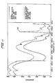
- Figures 9 - 14 are comparisons of infrared diffuse reflectance spectra for various materials obtained with and without the blocker of Figure 3.
- Figure 9 is a comparison of an infrared spectrum of neat, ground sand obtained by diffuse reflectance.
- Curve a is a measure of the spectrum obtained without a blocker device using the entire output half of the ellipsoid mirror 6 of Figure 2.
- Curve b is a spectrum obtained by masking region 10 of the ellipsoid mirror 6.
- Curve c is the spectrum produced when region 12 is masked. Specular distortion of the diffuse reflectance spectrum is present in all three cases.
- Curve d shows that a dramatic reduction in the specular reflectance can be obtained by roughening the surface of the sample.
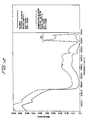
- Figure 10 shows a comparison between curve a of Figure 9, i.e., the diffuse spectrum employing the full output half of the ellipsoid mirror 6, and a diffuse spectrum e obtained using the blocker device.
- Curve d in Figure 9 obtained by roughening the surface produces markedly less specular distortion.
- spectrum e of Figure 10 contains substantially less specular distortion than even curve d.
- This effect is most noticeable by comparing the peak value of the spectral feature labelled generally 100.
- Spectral feature 100 is pronounced in curve a containing the highest specutar component. Even curve d contains some element of this distortion.
- Spectral feature 100 is completely absent in curve e.
- spectral feature 100 is an example of the nature of the distortion introduced into a diffuse reflectance spectrum by specular reflection.
- spectral feature 101 appears to be an example of a band inversion or reststrahlen band.
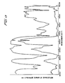
- Figure 11 shows another infrared comparison spectrum of silica.
- the upper line shows the spectrum having a specular component.
- the lower spectrum shows the spectrum obtained with the use of the blocker. Note again how spectrum feature 105 totally disappears with the use of the blocker device.
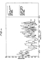
- Figure 12 shows comparison spectra for alumina. Note how specular reflectance feature 110 disappears in the diffuse reflectance spectra obtained with the blocker device.
- Figure 13 shows comparison diffuse reflectance spectra without and with a blocker for finely powdered calcite. The energy distribution across wavelengths between the two spectra is clearly different.
- Figure 14 is a comparison spectrum of aqueous ethylanthroquinone. This solution, as is true for most organic compounds, does not exhibit spectral distortions caused by specular reflection due to the absence of strong resonance bands at infrared frequencies. Thus, the blocker does not significantly change the spectrum obtained through unblocked diffuse reflectance spectroscopy.
Description
- This invention deals with a method and apparatus for obtaining diffuse reflectance spectra, wherein the specular component of the diffuse spectra is substantially eliminated. Distortions in the diffuse reflectance spectra caused by the specular component are thus eliminated.
- It is known that particular compounds possess unique spectral signatures. One method to obtain a spectrum indicative of a particular compound is transmission spectroscopy. A transmission spectrum can be obtained by transmitting an energy beam of known intensity and frequency through an at least partially transmissive sample and recording the intensity of the energy transmitted through the sample at various incident wavelengths. This method works quite well for a wide range of compounds having known transmission spectra. More recent technology for obtaining infrared spectra uses interferometers and computers in what is commonly called Fourier Transform Infrared (FTIR) spectroscopy. This technology has proved to have significant advantages over prior art methods of obtaining infrared spectra. A transmission spectrum cannot, generally, be obtained for a compound composed of powder grains or small size granules, particularly when the powder is substantially opaque to the frequencies of the incident energy at common granule thickness. One solution in such an instance is to embed the powder or granules in a matrix not having spectral features in the frequency range of the incident energy beam. This method only works so long as a suitable matrix compound can be found and the powder or granules are not so opaque as to absorb all input energy when the matrix contains a sufficient density of the sample to produce a meaningful spectrum from the sample.
- Another solution to the problem associated with powders or granular samples is to obtain a diffuse reflectance spectrum of the sample. A diffuse reflectance spectrum is obtained by directing an input energy beam onto the surface of the sample, collecting the diffusely reflected energy from the sample and directing that energy to a detector. Diffusely reflected energy is energy which is defined to be reflected from below the surface of the sample. The energy diffusely reflected from a sample does not have a preferred direction of reflection, i.e., the diffusely reflected energy leaves the sample surface in a hemispherical pattern. The diffusely reflected energy has spectral characteristics that uniquely identify the sample compounds and correspond to the spectrum obtained by transmissive means.
- In addition to diffuse reflection, however, an energy beam directed against the surface of a sample produces specular reflection. Specular reflection is defined to be incident energy that is reflected from a surface of a sample as opposed to diffusely reflected energy which is energy reflected from below the sample surface. Specular reflectance obeys Snell's Law which states that the angle of incidence of the input energy beam equals the angle of reflectance. In other words, energy that is specularly reflected behaves as light reflected from a mirror. Thus, if all the crystals on the surface of a powder sample were oriented so as to present a homogenous reflective face to the incident energy that was parallel to the plane of the sample, the incident energy would reflect off the surface of the sample according to Snell's Law. However, the reflecting surfaces of individual crystals on the surface of a powder sample are somewhat randomly oriented and, therefore, scatter the incident energy over an entire hemisphere as is the case for diffuse reflection. Our experiments and those of others have shown that the crystals on the surface of a sample may often be oriented so as to produce a preferred direction of reflection. Nevertheless, some of the incident energy beam is nearly always specularly reflected over all angles of reflection. A detailed discussion of the spectrometry of powdered samples is found in Griffiths et al, Advances in Infrared and Raman Spectroscopy, Vol. 9,
Chapter 2, (Heyden, London 1981). - Conventional analysis of diffuse reflectance spectra employs the Kubelka-Munk function. The Kubelka-Munk function states that the strength of an absorption feature in a diffuse reflectance spectrum is linearly related to the concentration of the compound producing the spectral feature. The function involves a relationship between an absorption coefficient, a scattering coefficient and the ratio of the diffuse reflectance from a sample and that of a non-absorbing powder reference. The function assumes that the sample extends to an infinite optical depth, i.e., that depth at which the addition of more sample material to the bottom of the sample does not change the amount of energy diffusely reflected. In theory, the Kubelka-Munk function should enable a spectrum obtained by diffuse reflectance to be compared to a spectrum obtained by transmissive means. The transmission spectrum for many compounds is known. Hence, the ability to identify a compound from its diffuse reflectance spectrum given a known transmission spectrum enables diffuse reflectance spectroscopy to accurately identify trace elements present in powdered samples that do not lend themselves to direct transmission spectroscopy. A specific example of the application of diffuse reflection spectroscopy is in quality control of pharmaceutical tablets to eliminate the need to grind up the tablets and embed them in a non-absorbtive matrix. Moreover, it is believed that it will be possible to apply spectral substraction routines commonly used in absorption spectroscopy to diffuse reflectance measurements to identify trace elements in the sample and to accurately establish their concentration in the sample.
- The linearity of the Kubelka-Munk relationship for the strength of an absorption feature with concentration, however, breaks down for experimental conditions involving specular reflection. Specular reflection alters a diffuse spectrum in a complex manner which is not well understood. The spectrum produced from specular reflection is a complex, nonlinear function dependent on wavelength, particle size, index of refraction of the particular materials present in the sample, the presence or absence of an absorption band in the surface material and the strength of the band. Moreover, the spectrum obtained from a diffusely reflecting sample may change by simply changing the orientation of the sample or by merely brushing the surface of the sample. At best, specular reflectance convolves the Kubelka-Munk relationship with another slightly nonlinear function. In certain instances, such as for inorganic samples at infrared energies, the effect of specular reflectance is more severe, producing complete inversion of spectral bands, referred to as reststrahlen bands, or derivative shaped spectral peaks. The effect of specular reflectance is to make quantitative analysis of the diffuse spectrum an extremely complicated and error prone undertaking. In many cases, qualitative interpretation of the diffuse reflectance spectrum convolved with specular reflection produces erroneous information as to the composition or concentration of a sample. Therefore, to obtain accurate and useful information, it is highly desirable to eliminate the specular reflectance component from the diffuse reflectance spectra.
- As noted above, specular reflection behaves like a mirror with incident energy reflected from a powder surface according to Snell's Law without penetrating into the sample. Any specular component should ideally leave the sample with a smaller angular spread than the diffuse component. Although powdered or granular surfaces adhere to Snell's Law for individual granules, the reflection properties of the aggregate surface can be quite different. However, surface preparation techniques could be used to orient the surface granules so that Snell's Law reasonably approximates the reflectance off the surface. Therefore, certain collection angles could, in principle, contain a pure diffuse reflection spectrum, and rotation of the collection mirror away from a symmetrical collection angle would eliminate the specular component of the energy reflected back from the sample.
- Our experiments have shown that specular reflection may indeed have a preferential orientation along the direction predicated by Snell's Law. However, some specularly reflected energy has been found at all angles of reflection. The magnitude of the specular component over a given angle is a function of the manner in which the sample cup is filled and prepared. Standard practice in examining a powder sample has included drawing a straight edge across the powder surface prior to taking a spectrum. This manner of preparing the surface appears to be highly effective at orienting individual crystals and increases the likelihood that a comparable diffuse reflectance spectrum may be obtained from samples that are identical in composition. However, orienting the surface crystals increases the magnitude of energy that is specularly reflected towards the detector without confining the specular reflection to a particular angle. Thus, while this method might improve repeatability inherent distortions are also repeated.
- Roughening the surface of the sample reduces the total amount of specular reflectance directed towards the collector. The roughening may take the form of drawing a camel hair brush over the sample or placing a piece of adhesive tape in light contact with the top of the sample and subsequently removing the tape. However, roughening the surface to the same degree is difficult and does not completely eliminate the specular component. Indeed, a completely roughened surface having crystals randomly oriented produces specular reflection over all angles of reflection without a known preferred orientation.
- Another method of attempting to eliminate the specular component from a diffuse reflectance spectrum involves diluting the specularly reflective sample in a matrix having no spectral features at the wavelength of the incident energy and no distorted specular reflectance properties. This method is subject to the limitation of being able to find an inert matrix material that does not have absorptive or reflective properties in the given range of energy. The method often requires destroying the sample so that it can be mixed with the matrix material.
- The foregoing discussion demonstrates an acknowledged need for some means by which to eliminate specular reflection from diffuse reflectance spectra. We have found a particular need for eliminating the distortion caused by specular reflectance in obtaining diffuse reflectance spectra of inorganic compounds. This is because certain inorganic compounds are not suited for infrared analysis by transmissive means and may not be analyzed with any of the foregoing methods due to the extreme distortion of their diffuse reflectance spectrum caused by their inherent specular properties. More generally, there has not hitherto been a simple means for quickly and economically obtaining an undistorted diffuse reflectance spectrum of any sample having specular reflective properties that is not subject to random distortions caused by the orientation of granules on the surface of the sample.
- From EP-A-0 125 340 a reflectance apparatus for obtaining measurement of nonspecular reflected light is known in which one or more light sources and one or more detectors are mounted together on the same plane surface in close proximity to each other at an angle (Φ) from the normal to the surface of the specimen. The angle (Φ) is selected such that specular reflection at the surface of the specimen is insignificant compared to the minimum diffused reflection expected from the specimen.
- The invention is directed to a method and apparatus for eliminating specular reflectance from the diffuse reflectance spectrum of a reflecting sample. In most general terms, the method comprises directing energy onto a surface of a sample, positioning a blocking element at or closely adjacent the surface of the sample to separate specularly reflected energy from diffusely reflected energy so that the diffusely reflected energy can be separately collected. The apparatus of the invention preferably includes means for providing an input beam of energy, means for focusing and collecting energy onto and from a reference sample and means for eliminating substantially all specularly reflected energy from the energy collected from the sample. More specifically, the invention preferably utilizes a thin blade as the blocking element (also referred to as the blocker) placed in substantial contact with the surface of the sample at the intersection of the surface with the incident energy beam to substantially eliminate the specular reflection from the diffusely reflected energy beam.
- Certain embodiments of the invention will now be described by way of example and with reference to the accompanying drawings.
-
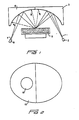
- Fig. 1 is a schematic side view illustrating the light path taken by light impinging upon a diffusely and specularly reflecting sample.
- Fig. 2 is a bottom view of the focusing ellipsoid in Fig. 1.
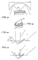
- Figs. 3A and 3B schematically show in side and perspective views a specular blocker device according to the present invention in use in conjunction with the apparatus shown in Fig. 1.
- Figs. 4A and B show a cross section of an edge of a blocking element contacting the surface of the sample for use in the arrangement shown in Fig. 3.
- Figs. 5A and 5B show in cross section the effect of a blocker blade inserted below the surface of a sample.
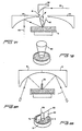
- Figs. 6A and B show an alternative embodiment of the invention.
- Figs. 7A and 7B represent an alternative embodiment of the blocker shown in Fig. 3.
- Figs. 8A and B show a further alternative embodiment of a blocker for use in an arrangement as depicted in Fig. 3.
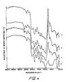
- Figs. 9 and 10 show comparison spectra from ground sand showing how the distortions caused by specular reflection are eliminated through using the blocker of the invention.
- Fig. 11 provides a comparison of diffusive spectra obtained from silica demonstrating the effect of the blocker according to the present invention at reducing the specular component of diffusive spectra.
- Fig. 12 shows a similar comparison to Fig. 11 for alumina powder.
- Fig. 13 shows a spectrum similar to Fig. 11 for finely powdered calcite.
- Fig. 14 shows comparison spectra with and without the blocker of the present invention for ethylanthroquinone showing how the blocker does not have a substantial effect on the spectrum of a compound lacking a large degree of specular reflectance.
- Figure 1 shows the effect of diffuse scattering from a sample. An
input beam 1 emitted fromsource 2 reflects off a focusingellipsoid mirror 3 onto asample 5. While infrared light is the most common energy for use in the method, energy of other wavelengths may be suitable. Reflected energy bounces offsample 5 onto an output half of theellipsoid mirror 6 to focus 7 where it is targeted on the detector 8. At most, one-half the input energy reaches the output half of the ellipsoid mirror because the diffusely reflected light from the sample is reflected over all angles. - If
sample 5 is replaced with a mirror, all the reflective energy will fall onregion 10 as shown in Figure 2. Thus, specularly reflected energy from a sample would, under ideal conditions, obey Snell's Law and fall only onregion 10. However, in practice, specularly reflected energy falls on bothregions ellipsoid mirror 6 due to random orientation of the crystals on the surface of the sample. - In
Figure 3A blocker 20 according to the present invention is positioned over thesample 5 which is contained incup 9. In a preferred embodiment of the invention, the blocker is a straight edged piece of metal, although any material that is opaque to the incident energy may suffice. The blocker should be made from material that does not have reflective spectral features in the energy range of the input beam. This requirement is satisfied for the infrared region by gold plating the blocker because gold is completely reflective in the infrared region. A blocker coated with a material that is completely absorbent of the incident energy could also be employed. -
Blocker 20 is positioned relative to sample 5 and the focus ofinput beam 1 reflected off focusingellipsoid mirror 3 to eliminate the specular component of reflected energy fromsample 5 by physically blocking the energy reflected from the surface of the sample. Any means for holding the blocker in position can be employed. A preferred means is achieved by mounting the blocker on a pivoting arm which allows it to be moved into position during operation and pivotally out of position to facilitate replacement of the sample. It is important that the blocker contacts the surface of the sample so as to prevent specularly reflected input radiation from leaking under the blocker and reaching the output half of theellipsoid 6. The blocker must be separated from the surface by less than a wavelength of the incident energy. If the blocker is to prevent specularly reflected input energy from leaking under a bottom edge of the blocker the physical contact of a metal blocker with the surface of the sample may also advantageously eliminate light waves propagating along the surface of the sample that may form a component of the specularly reflected light. - The intersection of the blocker and the surface of the sample should be located on the sample at the focus of the input energy being reflected off focusing
ellipsoid mirror 3. As shown in Figure 3B, the blocker splits the image focal plane of the input beam on the surface ofsample 5. - To obtain maximum efficiency and the closest approximation to the Kubelka-Munk relationship, a blocker should have an edge of a thickness that is a fraction of the optical depth of the sample. Such a blade may be considered a thin blocker. A thicker blocker, by removing energy that penetrates only a short distance into the sample before reflecting, may have a catastrophic effect on efficiency when used with a sample having a shallow optical depth because input energy that penetrates to only a shallow depth may contain the majority of the energy diffused into the sample. This effect is as shown in Figure 4A.
Lines 15 represent energy rays fromfocused input beam 1 which penetrate thesample 5 and are diffusely reflected. As shown by this figure, only a small fraction of the energy escapes from the far side of the blocker. A thick blocker may also introduce spectral distortions caused by energy that is once reflected by the sample to the lower surface of the blocker and again reflected from the blocker to the sample before the energy escapes from the far side of the blocker as shown byline 16 in Figure 4A. Energy thus reflected from the surface of the blocker will acquire any reflectance spectral features of the blocker itself and, thus, distort the output spectrum. Therefore, the blade edge of the blocker device should be made as thin as possible to maximize the efficiency of the device as is shown in Figure 4B minimizing surface spectra of the blocker and permitting a great portion of the diffusively reflectedenergy 15 to escape from the far side of the blocker. - Efficiency also dictates that the blocker not penetrate the surface of the sample. As shown in Figure 5A, penetration of the blocker into the sample blocks energy 17 that is reflected from a shallow depth and has an effect that is comparable to employing a thick blocker. In practice, however, it is sometimes necessary to break the surface of the sample with the blocker to ensure that specularly reflected energy will not leak underneath the blocker at some point along the edge of the blocker as shown by
ray 18 in Figure 5B. - The need for penetrating the surface of a sample may be eliminated by smoothing the sample prior to moving the blocker and sample into position. One means of accomplishing this is shown in Figures 6A and B. A flattening window is made of
transmissive material 25 having two flattenededges blocker 20. The window is positioned on the sample so thatface 27 lightly presses or touches the surface of thesample 5 so as to smooth any surface irregularities and eliminate any leaking of specularly reflected energy under the blocker. - Figures 7A and 7B show a further embodiment of the invention. An input beam 30 is directed downward by a focusing
paraboloid mirror 32 onto the sample at a substantially vertical angle. Energy penetrating the surface which is diffusively reflected exits the sample and is collected bycollection mirror 33. In this embodiment, theblocker 40 assumes the shape of a cone. The tip of the cone contains an exit hole having a diameter equal to the diameter of the input beam. Specularly reflected light reflects back off the surface of the sample and exits the system by either directly reflecting back offinput paraboloid mirror 32 or bymultiple reflections 41 off the blocker thus removing all specularly reflected light fromoutput beam 45. This embodiment has the advantage of collecting diffusely reflected light from a much greater portion of a hemisphere. - Figures 8A and 8B show a further embodiment of the invention.
Blocker 50 has three surfaces.Surfaces Surface 56 is arcuate-shaped to match the shape of the edge of the input beam focused on the surface of the sample. The advantages to the arcuate shap will lie in potentially obtaining greater efficiency of use from the input beam in that the entire beam reaches the surface of the sample rather than having half of the beam reflected off the blocker as is the case for the blocker shown in Figure 3. - In general, the ideal optical arrangement for the blocker device has a symmetrical design where no attempt is made to otherwise optically exclude specular energy. Therefore, all energy received by the output half of the
ellipsoid mirror 6 in Figure 1 should be directed to focus 7. The blocker has proven so effective at removing the specular component of reflected energy that no need exists to discriminate between light received byareas - It is believed that the blocker will result in the linearization of the output spectrum according to the Kubelka-Munk formula since present theory maintains that deviations of diffuse reflectance spectra from the Kubelka-Munk relationship are produced solely or primarily by specular reflection.
- Figures 9 - 14 are comparisons of infrared diffuse reflectance spectra for various materials obtained with and without the blocker of Figure 3. Figure 9 is a comparison of an infrared spectrum of neat, ground sand obtained by diffuse reflectance. Curve a is a measure of the spectrum obtained without a blocker device using the entire output half of the
ellipsoid mirror 6 of Figure 2. Curve b is a spectrum obtained by maskingregion 10 of theellipsoid mirror 6. Curve c is the spectrum produced whenregion 12 is masked. Specular distortion of the diffuse reflectance spectrum is present in all three cases. Curve d shows that a dramatic reduction in the specular reflectance can be obtained by roughening the surface of the sample. - Figure 10 shows a comparison between curve a of Figure 9, i.e., the diffuse spectrum employing the full output half of the
ellipsoid mirror 6, and a diffuse spectrum e obtained using the blocker device. Curve d in Figure 9 obtained by roughening the surface produces markedly less specular distortion. However, spectrum e of Figure 10 contains substantially less specular distortion than even curve d. This effect is most noticeable by comparing the peak value of the spectral feature labelled generally 100.Spectral feature 100 is pronounced in curve a containing the highest specutar component. Even curve d contains some element of this distortion.Spectral feature 100 is completely absent in curve e. Thus,spectral feature 100 is an example of the nature of the distortion introduced into a diffuse reflectance spectrum by specular reflection. Note that in Figure 10spectral feature 101 appears to be an example of a band inversion or reststrahlen band. - Figure 11 shows another infrared comparison spectrum of silica. The upper line shows the spectrum having a specular component. The lower spectrum shows the spectrum obtained with the use of the blocker. Note again how spectrum feature 105 totally disappears with the use of the blocker device.
- Similarly, Figure 12 shows comparison spectra for alumina. Note how
specular reflectance feature 110 disappears in the diffuse reflectance spectra obtained with the blocker device. - Figure 13 shows comparison diffuse reflectance spectra without and with a blocker for finely powdered calcite. The energy distribution across wavelengths between the two spectra is clearly different.
- The foregoing figures illustrate the common presence of specular reflection distortion in infrared diffuse reflectance spectroscopy and how this distortion can be eliminated through use of the blocker device.
- Not all diffusely reflecting compounds produce specular distortion. Figure 14 is a comparison spectrum of aqueous ethylanthroquinone. This solution, as is true for most organic compounds, does not exhibit spectral distortions caused by specular reflection due to the absence of strong resonance bands at infrared frequencies. Thus, the blocker does not significantly change the spectrum obtained through unblocked diffuse reflectance spectroscopy.
- Operation of the blocker device according to the present invention has been descibed by way of example as applied to infrared spectroscopy. As noted, the blocker has particular utility in the field of infrared diffuse spectroscopy of inorganic compounds. However, the foregoing specification enables one of ordinary skill in the art to apply the principles of the blocker device to any instance where an energy beam consisting of a particle demonstrating significant quantum mechanical wave properties is incident on the surface of a material that reflects the incident beam at both the surface of the material and from below the surface. Therefore, the invention which is intended to be protected herein should not be construed as limited to the particular forms described, as these are to be regarded as illustrative rather than restrictive. Variations and changes may be made by those skilled in the art without departing from the scope of the present invention. Accordingly, the foregoing detailed description should be considered exemplary in nature and not as limiting to the scope of the invention as set forth in the appended claims.
Claims (21)
Applications Claiming Priority (2)
| Application Number | Priority Date | Filing Date | Title |
|---|---|---|---|
| US06/705,201 US4661706A (en) | 1985-02-25 | 1985-02-25 | Blocker device for eliminating specular reflectance from a diffuse reflection spectrum |
| US705201 | 1985-02-25 |
Publications (2)
| Publication Number | Publication Date |
|---|---|
| EP0200302A1 EP0200302A1 (en) | 1986-11-05 |
| EP0200302B1 true EP0200302B1 (en) | 1989-05-10 |
Family
ID=24832473
Family Applications (1)
| Application Number | Title | Priority Date | Filing Date |
|---|---|---|---|
| EP86301307A Expired EP0200302B1 (en) | 1985-02-25 | 1986-02-24 | Blocker device for eliminating specular reflectance from a diffuse reflection spectrum |
Country Status (6)
| Country | Link |
|---|---|
| US (1) | US4661706A (en) |
| EP (1) | EP0200302B1 (en) |
| JP (1) | JPS61196138A (en) |
| CN (1) | CN86101254A (en) |
| CA (1) | CA1255946A (en) |
| DE (1) | DE3663307D1 (en) |
Families Citing this family (75)
| Publication number | Priority date | Publication date | Assignee | Title |
|---|---|---|---|---|
| US4764676A (en) * | 1986-10-20 | 1988-08-16 | Laser Precision Corporation | Apparatus for spectral analysis of chromatographic fractions |
| US4853542A (en) * | 1987-06-08 | 1989-08-01 | Nicolas J. Harrick | Collecting hemispherical attachment for spectrophotometry |
| US4965454A (en) * | 1988-01-21 | 1990-10-23 | Hitachi, Ltd. | Method and apparatus for detecting foreign particle |
| US4859064A (en) * | 1988-05-09 | 1989-08-22 | Spectra-Tech, Inc. | Diffuse reflectance spectroscopy system and method |
| US5058982A (en) * | 1989-06-21 | 1991-10-22 | Orbot Systems Ltd. | Illumination system and inspection apparatus including same |
| JPH064841B2 (en) * | 1989-06-28 | 1994-01-19 | 日本鋼管株式会社 | Method of manufacturing infrared scattering agent |
| GB9016587D0 (en) * | 1990-07-27 | 1990-09-12 | Isis Innovation | Infra-red scanning microscopy |
| DE4331596A1 (en) * | 1993-09-17 | 1995-03-23 | Boehringer Mannheim Gmbh | Method for the quantitative analysis of sample liquids |
| US6982794B1 (en) | 1995-06-07 | 2006-01-03 | The Boeing Company | Directional reflectometer |
| US6152876A (en) * | 1997-04-18 | 2000-11-28 | Rio Grande Medical Technologies, Inc. | Method for non-invasive blood analyte measurement with improved optical interface |
| US5655530A (en) * | 1995-08-09 | 1997-08-12 | Rio Grande Medical Technologies, Inc. | Method for non-invasive blood analyte measurement with improved optical interface |
| US5636633A (en) * | 1995-08-09 | 1997-06-10 | Rio Grande Medical Technologies, Inc. | Diffuse reflectance monitoring apparatus |
| US6240306B1 (en) | 1995-08-09 | 2001-05-29 | Rio Grande Medical Technologies, Inc. | Method and apparatus for non-invasive blood analyte measurement with fluid compartment equilibration |
| US6212424B1 (en) | 1998-10-29 | 2001-04-03 | Rio Grande Medical Technologies, Inc. | Apparatus and method for determination of the adequacy of dialysis by non-invasive near-infrared spectroscopy |
| US6628809B1 (en) | 1999-10-08 | 2003-09-30 | Lumidigm, Inc. | Apparatus and method for identification of individuals by near-infrared spectrum |
| US7890158B2 (en) | 2001-06-05 | 2011-02-15 | Lumidigm, Inc. | Apparatus and method of biometric determination using specialized optical spectroscopy systems |
| US6560352B2 (en) | 1999-10-08 | 2003-05-06 | Lumidigm, Inc. | Apparatus and method of biometric identification or verification of individuals using optical spectroscopy |
| CN1314997A (en) * | 1998-06-16 | 2001-09-26 | 奥宝科技有限公司 | Illuminator for inspecting substantially flat surfaces |
| US6157041A (en) * | 1998-10-13 | 2000-12-05 | Rio Grande Medical Technologies, Inc. | Methods and apparatus for tailoring spectroscopic calibration models |
| US7098037B2 (en) * | 1998-10-13 | 2006-08-29 | Inlight Solutions, Inc. | Accommodating subject and instrument variations in spectroscopic determinations |
| US6441388B1 (en) | 1998-10-13 | 2002-08-27 | Rio Grande Medical Technologies, Inc. | Methods and apparatus for spectroscopic calibration model transfer |
| IL131284A (en) | 1999-08-05 | 2003-05-29 | Orbotech Ltd | Illumination for inspecting surfaces of articles |
| US6816605B2 (en) | 1999-10-08 | 2004-11-09 | Lumidigm, Inc. | Methods and systems for biometric identification of individuals using linear optical spectroscopy |
| DE19962428A1 (en) * | 1999-12-22 | 2001-06-28 | Siemens Ag | Process for optical and spectroscopic measurement of the properties of solid materials and associated equipment |
| US6483590B1 (en) | 2000-12-18 | 2002-11-19 | The Boeing Company | Instrument for rapidly characterizing material reflectance properties |
| US20070276199A1 (en) * | 2002-04-04 | 2007-11-29 | Ediger Marwood N | Determination of a Measure of a Glycation End-Product or Disease State Using Tissue Fluorescence |
| US7126682B2 (en) * | 2001-04-11 | 2006-10-24 | Rio Grande Medical Technologies, Inc. | Encoded variable filter spectrometer |
| US6865408B1 (en) | 2001-04-11 | 2005-03-08 | Inlight Solutions, Inc. | System for non-invasive measurement of glucose in humans |
| US6862091B2 (en) | 2001-04-11 | 2005-03-01 | Inlight Solutions, Inc. | Illumination device and method for spectroscopic analysis |
| US7043288B2 (en) | 2002-04-04 | 2006-05-09 | Inlight Solutions, Inc. | Apparatus and method for spectroscopic analysis of tissue to detect diabetes in an individual |
| US6983176B2 (en) | 2001-04-11 | 2006-01-03 | Rio Grande Medical Technologies, Inc. | Optically similar reference samples and related methods for multivariate calibration models used in optical spectroscopy |
| US7139598B2 (en) * | 2002-04-04 | 2006-11-21 | Veralight, Inc. | Determination of a measure of a glycation end-product or disease state using tissue fluorescence |
| US6574490B2 (en) | 2001-04-11 | 2003-06-03 | Rio Grande Medical Technologies, Inc. | System for non-invasive measurement of glucose in humans |
| US7027848B2 (en) | 2002-04-04 | 2006-04-11 | Inlight Solutions, Inc. | Apparatus and method for non-invasive spectroscopic measurement of analytes in tissue using a matched reference analyte |
| US6654125B2 (en) | 2002-04-04 | 2003-11-25 | Inlight Solutions, Inc | Method and apparatus for optical spectroscopy incorporating a vertical cavity surface emitting laser (VCSEL) as an interferometer reference |
| US8131332B2 (en) * | 2002-04-04 | 2012-03-06 | Veralight, Inc. | Determination of a measure of a glycation end-product or disease state using tissue fluorescence of various sites |
| US8140147B2 (en) * | 2002-04-04 | 2012-03-20 | Veralight, Inc. | Determination of a measure of a glycation end-product or disease state using a flexible probe to determine tissue fluorescence of various sites |
| US7620212B1 (en) | 2002-08-13 | 2009-11-17 | Lumidigm, Inc. | Electro-optical sensor |
| US7623906B2 (en) * | 2002-11-12 | 2009-11-24 | Inlight Solutions, Inc | Diffuse reflectance spectroscopy |
| US7751594B2 (en) | 2003-04-04 | 2010-07-06 | Lumidigm, Inc. | White-light spectral biometric sensors |
| US7394919B2 (en) | 2004-06-01 | 2008-07-01 | Lumidigm, Inc. | Multispectral biometric imaging |
| US7347365B2 (en) * | 2003-04-04 | 2008-03-25 | Lumidigm, Inc. | Combined total-internal-reflectance and tissue imaging systems and methods |
| US7627151B2 (en) * | 2003-04-04 | 2009-12-01 | Lumidigm, Inc. | Systems and methods for improved biometric feature definition |
| US7545963B2 (en) | 2003-04-04 | 2009-06-09 | Lumidigm, Inc. | Texture-biometrics sensor |
| US7668350B2 (en) * | 2003-04-04 | 2010-02-23 | Lumidigm, Inc. | Comparative texture analysis of tissue for biometric spoof detection |
| US7539330B2 (en) * | 2004-06-01 | 2009-05-26 | Lumidigm, Inc. | Multispectral liveness determination |
| US7460696B2 (en) | 2004-06-01 | 2008-12-02 | Lumidigm, Inc. | Multispectral imaging biometrics |
| KR20060002923A (en) * | 2003-04-04 | 2006-01-09 | 루미다임 인크. | Multispectral biometric sensor |
| US20050007582A1 (en) * | 2003-07-07 | 2005-01-13 | Lumidigm, Inc. | Methods and apparatus for collection of optical reference measurements for monolithic sensors |
| US20050073690A1 (en) * | 2003-10-03 | 2005-04-07 | Abbink Russell E. | Optical spectroscopy incorporating a vertical cavity surface emitting laser (VCSEL) |
| US7263213B2 (en) | 2003-12-11 | 2007-08-28 | Lumidigm, Inc. | Methods and systems for estimation of personal characteristics from biometric measurements |
| US20110163163A1 (en) * | 2004-06-01 | 2011-07-07 | Lumidigm, Inc. | Multispectral barcode imaging |
| US8229185B2 (en) * | 2004-06-01 | 2012-07-24 | Lumidigm, Inc. | Hygienic biometric sensors |
| US7508965B2 (en) * | 2004-06-01 | 2009-03-24 | Lumidigm, Inc. | System and method for robust fingerprint acquisition |
| US8787630B2 (en) | 2004-08-11 | 2014-07-22 | Lumidigm, Inc. | Multispectral barcode imaging |
| WO2006076810A1 (en) * | 2005-01-21 | 2006-07-27 | Perceptronix Medical Inc. | Method And Apparatus For Measuring Cancerous Changes From Reflectance Spectral Measurements Obtained During Endoscopic Imaging |
| US7801338B2 (en) * | 2005-04-27 | 2010-09-21 | Lumidigm, Inc. | Multispectral biometric sensors |
| US7978332B2 (en) * | 2006-04-18 | 2011-07-12 | Koninklijke Philips Electronics N.V. | Optical measurement device |
| US7995808B2 (en) * | 2006-07-19 | 2011-08-09 | Lumidigm, Inc. | Contactless multispectral biometric capture |
| US8355545B2 (en) * | 2007-04-10 | 2013-01-15 | Lumidigm, Inc. | Biometric detection using spatial, temporal, and/or spectral techniques |
| US8175346B2 (en) * | 2006-07-19 | 2012-05-08 | Lumidigm, Inc. | Whole-hand multispectral biometric imaging |
| CN103336941A (en) * | 2006-07-19 | 2013-10-02 | 光谱辨识公司 | Multibiometric multispectral imager |
| US7801339B2 (en) | 2006-07-31 | 2010-09-21 | Lumidigm, Inc. | Biometrics with spatiospectral spoof detection |
| US7804984B2 (en) | 2006-07-31 | 2010-09-28 | Lumidigm, Inc. | Spatial-spectral fingerprint spoof detection |
| WO2008134135A2 (en) * | 2007-03-21 | 2008-11-06 | Lumidigm, Inc. | Biometrics based on locally consistent features |
| US20100246902A1 (en) * | 2009-02-26 | 2010-09-30 | Lumidigm, Inc. | Method and apparatus to combine biometric sensing and other functionality |
| WO2010148458A1 (en) * | 2009-06-25 | 2010-12-29 | Commonwealth Scientific And Industrial Research Organisation | Method of detecting contaminants |
| EP2471023A1 (en) * | 2009-08-26 | 2012-07-04 | Lumidigm, Inc. | Multiplexed biometric imaging and dual-imager biometric sensor |
| US8570149B2 (en) | 2010-03-16 | 2013-10-29 | Lumidigm, Inc. | Biometric imaging using an optical adaptive interface |
| CN102401796B (en) * | 2010-09-09 | 2017-02-01 | 艾博生物医药(杭州)有限公司 | Device for reading assay result from assay carrier |
| CA2859249A1 (en) * | 2011-12-16 | 2013-06-20 | Glaxo Group Limited | Apparatus for testing samples using raman radiation |
| CN103884734B (en) * | 2014-04-01 | 2016-01-20 | 河南师范大学 | The apparatus and method of a kind of continuous coverage material direction spectral emittance |
| IL240872A (en) * | 2015-08-27 | 2016-11-30 | Elbit Systems Land & C4I Ltd | System and method for object authenticity detection |
| EP3830553B1 (en) | 2018-07-30 | 2023-09-06 | Thermo Electron Scientific Instruments LLC | Diffuse reflectance apparatus |
| CN114295558B (en) * | 2021-12-31 | 2023-08-22 | 四川启睿克科技有限公司 | Portable Spectrometer |
Family Cites Families (11)
| Publication number | Priority date | Publication date | Assignee | Title |
|---|---|---|---|---|
| US3177757A (en) * | 1960-03-29 | 1965-04-13 | American Optical Corp | Method of performing reflective oximetry |
| US3564262A (en) * | 1968-02-07 | 1971-02-16 | Hach Chemical Co | Turbidimeter using a pressurized fluid container |
| US3854045A (en) * | 1970-10-21 | 1974-12-10 | Bergwerksverband Gmbh | Measuring the dust concentration in air |
| US4029391A (en) * | 1974-08-22 | 1977-06-14 | Sterndent Corporation | Light probe and interface therefor |
| US3947088A (en) * | 1974-08-22 | 1976-03-30 | Weber Dental Manufacturing Co. | Interface for light probe |
| US3962581A (en) * | 1975-10-06 | 1976-06-08 | Westvaco Corporation | Infra-red consistency meter |
| US4022534A (en) * | 1976-03-23 | 1977-05-10 | Kollmorgen Corporation | Reflectometer optical system |
| DE2848590A1 (en) * | 1978-11-09 | 1980-05-22 | Leitz Ernst Gmbh | OPTICAL ARRANGEMENT FOR REFLECTION MICROSCOPIC EXAMINATION OF BIOLOGICAL TISSUES AND ORGAN SURFACES |
| US4473295A (en) * | 1981-08-31 | 1984-09-25 | Laser Precision Corporation | Parabolic focusing apparatus for optical spectroscopy |
| DE3226370A1 (en) * | 1982-07-14 | 1984-01-19 | Compur-Electronic GmbH, 8000 München | REMISSION MEASURING HEAD |
| CA1201300A (en) * | 1982-11-01 | 1986-03-04 | Albert Brunsting | Optical readhead |
-
1985
- 1985-02-25 US US06/705,201 patent/US4661706A/en not_active Expired - Lifetime
-
1986
- 1986-02-10 CA CA000501488A patent/CA1255946A/en not_active Expired
- 1986-02-24 EP EP86301307A patent/EP0200302B1/en not_active Expired
- 1986-02-24 DE DE8686301307T patent/DE3663307D1/en not_active Expired
- 1986-02-25 JP JP61040151A patent/JPS61196138A/en active Pending
- 1986-02-25 CN CN198686101254A patent/CN86101254A/en active Pending
Also Published As
| Publication number | Publication date |
|---|---|
| DE3663307D1 (en) | 1989-06-15 |
| CA1255946A (en) | 1989-06-20 |
| EP0200302A1 (en) | 1986-11-05 |
| JPS61196138A (en) | 1986-08-30 |
| CN86101254A (en) | 1986-10-22 |
| US4661706A (en) | 1987-04-28 |
Similar Documents
| Publication | Publication Date | Title |
|---|---|---|
| EP0200302B1 (en) | Blocker device for eliminating specular reflectance from a diffuse reflection spectrum | |
| Khoshhesab | Reflectance IR spectroscopy | |
| US4859064A (en) | Diffuse reflectance spectroscopy system and method | |
| US6798503B2 (en) | Edge flaw inspection device | |
| WO1997020192A1 (en) | Methods and apparatus for characterizing a surface | |
| US7274445B1 (en) | Confocal scatterometer and method for single-sided detection of particles and defects on a transparent wafer or disk | |
| US20040027659A1 (en) | Sample holder | |
| KR100270009B1 (en) | Method and apparatus for imaging surface topography of a wafer | |
| CA2200337A1 (en) | Attenuated total reflectance sensing | |
| EP0396409A3 (en) | High resolution ellipsometric apparatus | |
| US3591287A (en) | Absorption spectrophotometry | |
| KR930703594A (en) | Simultaneous Multi-Angle / Multi-wavelength Elliptical Polarimeter and Measurement Method | |
| US5210418A (en) | Ultra-small sample analyzer for internal reflection spectroscopy | |
| US4972092A (en) | Apparatus for determining the effective surface roughness of polished optical samples by measuring the integral scattered radiation | |
| US5965889A (en) | Imaging stage for fourier transform infrared spectrometer | |
| Harrick et al. | Advances in optical spectroscopy: The ultra-small sample analyzer | |
| JPH1114561A (en) | Apparatus and method for measurement of x-rays | |
| US6128075A (en) | Diamond anvil spectroscope | |
| Lang et al. | The versatile sampling methods of infrared microspectroscopy | |
| US4886357A (en) | Internal reflection element with insensitive edges | |
| GB2056056A (en) | Detection or particles containing predominantly low atomic number nuclei | |
| US4303859A (en) | Infra-red analysis apparatus and method | |
| JP2000155102A (en) | X-ray measuring apparatus and method therefor | |
| Papini | Study of the relationship between particle sizes of polymer powders and their radiative properties | |
| JPH10160570A (en) | Powder atr measuring method, device therefor, and infrared spectrophotometer |
Legal Events
| Date | Code | Title | Description |
|---|---|---|---|
| PUAI | Public reference made under article 153(3) epc to a published international application that has entered the european phase |
Free format text: ORIGINAL CODE: 0009012 |
|
| AK | Designated contracting states |
Kind code of ref document: A1 Designated state(s): BE CH DE FR GB IT LI NL SE |
|
| 17P | Request for examination filed |
Effective date: 19870415 |
|
| 17Q | First examination report despatched |
Effective date: 19880811 |
|
| GRAA | (expected) grant |
Free format text: ORIGINAL CODE: 0009210 |
|
| AK | Designated contracting states |
Kind code of ref document: B1 Designated state(s): BE CH DE FR GB IT LI NL SE |
|
| PG25 | Lapsed in a contracting state [announced via postgrant information from national office to epo] |
Ref country code: IT Free format text: LAPSE BECAUSE OF FAILURE TO SUBMIT A TRANSLATION OF THE DESCRIPTION OR TO PAY THE FEE WITHIN THE PRE;WARNING: LAPSES OF ITALIAN PATENTS WITH EFFECTIVE DATE BEFORE 2007 MAY HAVE OCCURRED AT ANY TIME BEFORE 2007. THE CORRECT EFFECTIVE DATE MAY BE DIFFERENT FROM THE ONE RECORDED.SCRIBED TIME-LIMIT Effective date: 19890510 Ref country code: BE Effective date: 19890510 Ref country code: CH Effective date: 19890510 Ref country code: NL Effective date: 19890510 Ref country code: LI Effective date: 19890510 Ref country code: SE Effective date: 19890510 |
|
| REF | Corresponds to: |
Ref document number: 3663307 Country of ref document: DE Date of ref document: 19890615 |
|
| REG | Reference to a national code |
Ref country code: CH Ref legal event code: PL |
|
| EN | Fr: translation not filed | ||
| NLV1 | Nl: lapsed or annulled due to failure to fulfill the requirements of art. 29p and 29m of the patents act | ||
| PLBE | No opposition filed within time limit |
Free format text: ORIGINAL CODE: 0009261 |
|
| STAA | Information on the status of an ep patent application or granted ep patent |
Free format text: STATUS: NO OPPOSITION FILED WITHIN TIME LIMIT |
|
| 26N | No opposition filed | ||
| PGFP | Annual fee paid to national office [announced via postgrant information from national office to epo] |
Ref country code: FR Payment date: 19910114 Year of fee payment: 6 |
|
| PGFP | Annual fee paid to national office [announced via postgrant information from national office to epo] |
Ref country code: GB Payment date: 19910116 Year of fee payment: 6 |
|
| PGFP | Annual fee paid to national office [announced via postgrant information from national office to epo] |
Ref country code: DE Payment date: 19910129 Year of fee payment: 6 |
|
| ITTA | It: last paid annual fee | ||
| PG25 | Lapsed in a contracting state [announced via postgrant information from national office to epo] |
Ref country code: GB Effective date: 19920224 |
|
| GBPC | Gb: european patent ceased through non-payment of renewal fee | ||
| PG25 | Lapsed in a contracting state [announced via postgrant information from national office to epo] |
Ref country code: DE Effective date: 19921103 |
|
| PG25 | Lapsed in a contracting state [announced via postgrant information from national office to epo] |
Ref country code: FR Free format text: LAPSE BECAUSE OF FAILURE TO SUBMIT A TRANSLATION OF THE DESCRIPTION OR TO PAY THE FEE WITHIN THE PRESCRIBED TIME-LIMIT Effective date: 20000229 |
|
| PG25 | Lapsed in a contracting state [announced via postgrant information from national office to epo] |
Ref country code: FR Free format text: LAPSE BECAUSE OF FAILURE TO SUBMIT A TRANSLATION OF THE DESCRIPTION OR TO PAY THE FEE WITHIN THE PRESCRIBED TIME-LIMIT Effective date: 19920229 |