EP0199664A2 - Well pipe handling machine - Google Patents
Well pipe handling machine Download PDFInfo
- Publication number
- EP0199664A2 EP0199664A2 EP86630040A EP86630040A EP0199664A2 EP 0199664 A2 EP0199664 A2 EP 0199664A2 EP 86630040 A EP86630040 A EP 86630040A EP 86630040 A EP86630040 A EP 86630040A EP 0199664 A2 EP0199664 A2 EP 0199664A2
- Authority
- EP
- European Patent Office
- Prior art keywords
- pipe
- column structure
- well
- holding means
- support
- Prior art date
- Legal status (The legal status is an assumption and is not a legal conclusion. Google has not performed a legal analysis and makes no representation as to the accuracy of the status listed.)
- Granted
Links
Images


Classifications
-
- E—FIXED CONSTRUCTIONS
- E21—EARTH DRILLING; MINING
- E21B—EARTH DRILLING, e.g. DEEP DRILLING; OBTAINING OIL, GAS, WATER, SOLUBLE OR MELTABLE MATERIALS OR A SLURRY OF MINERALS FROM WELLS
- E21B19/00—Handling rods, casings, tubes or the like outside the borehole, e.g. in the derrick; Apparatus for feeding the rods or cables
- E21B19/02—Rod or cable suspensions
-
- E—FIXED CONSTRUCTIONS
- E21—EARTH DRILLING; MINING
- E21B—EARTH DRILLING, e.g. DEEP DRILLING; OBTAINING OIL, GAS, WATER, SOLUBLE OR MELTABLE MATERIALS OR A SLURRY OF MINERALS FROM WELLS
- E21B19/00—Handling rods, casings, tubes or the like outside the borehole, e.g. in the derrick; Apparatus for feeding the rods or cables
- E21B19/20—Combined feeding from rack and connecting, e.g. automatically
-
- E—FIXED CONSTRUCTIONS
- E21—EARTH DRILLING; MINING
- E21B—EARTH DRILLING, e.g. DEEP DRILLING; OBTAINING OIL, GAS, WATER, SOLUBLE OR MELTABLE MATERIALS OR A SLURRY OF MINERALS FROM WELLS
- E21B19/00—Handling rods, casings, tubes or the like outside the borehole, e.g. in the derrick; Apparatus for feeding the rods or cables
- E21B19/14—Racks, ramps, troughs or bins, for holding the lengths of rod singly or connected; Handling between storage place and borehole
-
- Y—GENERAL TAGGING OF NEW TECHNOLOGICAL DEVELOPMENTS; GENERAL TAGGING OF CROSS-SECTIONAL TECHNOLOGIES SPANNING OVER SEVERAL SECTIONS OF THE IPC; TECHNICAL SUBJECTS COVERED BY FORMER USPC CROSS-REFERENCE ART COLLECTIONS [XRACs] AND DIGESTS
- Y10—TECHNICAL SUBJECTS COVERED BY FORMER USPC
- Y10S—TECHNICAL SUBJECTS COVERED BY FORMER USPC CROSS-REFERENCE ART COLLECTIONS [XRACs] AND DIGESTS
- Y10S414/00—Material or article handling
- Y10S414/13—Handlers utilizing parallel links
Definitions
- This invention relates to machines for assisting in connecting a series of pipe stands to or disconnecting then from the upper end of a string of well pipe.
- the general purpose of the present invention is to provide an improved pipe handling machine which can be utilized in a conventional drilling rig with a standard derrick structure and which can perform all of the pipe handling and racking operations during a round trip with fewer persons on the rig, preferably a single operator, and desirably with no manual pipe handling steps.
- the machine can function under the control of a single operator to make and break threaded connections and move each stand very positively between a position of alignment with the well axis and a storage location.
- The, machine can handle stands of both drill pipe and drill collars, and can also be utilized for handling casing.
- a machine embodying the invention includes a support which preferably takes the form of a vertically extending column and which carries means for holding a pipe in vertically extending condition, and which is bodily shiftable to move the pipe from the location of the well axis to a laterally offset position near a storage rack.
- the pipe holding means desirably include two pipe holding units at vertically spaced locations for engaging and gripping the pipe at those spaced locations to very positively locate and control the movements of the pipe.
- Two synchronized drive mechanisms may engage the column at vertically spaced locations, preferably at the upper and lower ends of that structure,and be operable to move those portions in unison with one another in a manner effecting the desired horizontal bodily shifting movement of the column and carried parts while continuously maintaining the supported pipe in vertical condition.
- the pipe holding units and carried pipe stand may be shiftable laterally relative to the column structure to move the pipe to a racked position.
- the synchronized drive mechanisms desirably include pivotal connections mounting the column to pivot about a vertical axis in order to face in a proper direction for movement of the pipe stand into a racking board.
- the pipe holding units may be moved horizontally in correspondence with one another relative to the column to perform the racking and unracking function. This generally horizontal movement of the pipe holding units and carried pipe may be attained by connecting the units to the column through a parallelogram machanism having swinging arms mounting the two units respectively and swinging together toward and away from the column and relative to the racking board.
- the pipe holding means may be mounted to a carriage structure which is shiftable upwardly and downwardly relative to the main column structure or support of the apparatus.
- the machine may also include a spinner and torque wrench for making and breaking connections between the pipe string and a stand being connected to or detached from the string. These elements are preferably shiftable upwardly and downwardly with the carriage and pipe holding units, and the torque wrench may also be movable upwardly and downwardly relative to the spinner and other parts of the apparatus.
- the machine may include a control station in the form of a cab adapted to contain or support an operator and having control equipment for actuating the various movable parts of the apparatus.
- This control station may be mounted for movement upwardly and downwardly relative to the supporting column and with the pipe holding units and other elements, and preferably also for pivotal movement with the various pipe supporting parts and other related elements to properly face the racking board during movement of a pipe into or out of the rack.
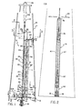
- a well pipe handling machine constructed in accordance with the invention and shown positioned within a somewhat diagrammatically represented drilling rig 11 including a derrick 12 having a rig floor 13 containing an opening 14 within which a slip assembly 15 is receivable for releasably supporting a drill string 16 extending along a vertical axis 17 and downwardly into a well 18.
- the rig is typically illustrated as a conventional arrangement in which the slip supporting opening 14 is contained within a rotary table 19 which turns the string during a drilling operation.
- the machine may also be utilized in a top drive system in which a motor connected to the upper end of the string drives it rotatively and is movable upwardly and downwardly with the string during drilling.
- the drill string is formed in conventional manner of a series of pipe sections 20 each having a lower externally threaded pin end 21 connected to an upper internally threaded box end 22 of the next successive section.
- the string is broken into a series of stands 23 each including three of the interconnected pipe sections 20, with these stands being moved by the machine 10 from the center line position of stand 23 in Fig. 1 to storage positions within a racking board assembly 24.
- the pipe string is raised and lowered by a remotely controlled elevator 25 suspended by links 26 from a traveling block 27, which in turn is suspended on a line 28 from a crown block 29 attached to the top of the derrick, with the line being actuable by draw works 30 to move the elevator upwardly and downwardly.
- the moving parts of machine 10 are carried principally by a vertical column structure 31 to which three carriages 32, 33 and 34 are mounted for upward and downward movement.
- the upper two carriages in turn support a parallelogram mechanism 35 having upper and lower arms 36 and 37 movably supporting an upper pipe holding or clamping unit 38 and a lower pipe holding or clamping unit 39.
- Carriage 33 also mounts a spinner 40 for turning the pipe rapidly, and the lower carriage 34 supports a torque wrench 41 and a control cab or station 42 within which the single operator of the machine is located.
- the column structure 31 is movably supported at its lower end on a base 42'connected to rig floor 13, and is connected movably at its upper end to racking board 24.
- Two synchronized drives 43 (Fig. 7) and 44 (Fig.
- Column structure 31 is a rigid vertical framework including two similar spaced parallel vertical column elements 47 joined together at their upper ends by a horizontal connector member 48 welded or otherwise secured to elements 47, and secured together at their lower ends by a horizontal connector member 49 also appropriately rigidly secured to elements 47.
- Elements 47 may have the hollow rectangular configuration illustrated in Fig. 10 along the entire vertical extent of elements 47.
- elements 47 rigidly carry an upper pair of vertical track or rail elements 50, and a similar lower pair of track or rail elements 50a, to guide the various carriages 32, 33 and 34 for upward and downward movement. All of these track members 50 and 50a may have the rectangular horizontal configuration illustrated in Fi g . 10.
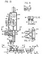
- the base 42'on which column structure 31 is mounted (Figs. 12 and 13) is a rigid structure appropriately bolted or otherwise secured in fixed position on the rig floor 13, and typically including two parallel side beams 51 acting as load support beams and carrying a horizontal top plate 52 extending across the upper side of base 42', with two parallel horizontal tracks 53 being welded, bolted or otherwise secured to plate 52 and beams 51.
- Tracks 53 are located at opposite sides of and equidistant from, and extend parallel to, a vertical plane 54 (Fig. 14) which contains the main vertical axis 17 of the well and extends radially with respect thereto.
- a carriage 55 is movable horizontally along tracks 53 and radially with respect to well axis 17, and may include upper and lower rigid plates 56 and 57 and vertical connectors 58 extending between and securing together the plates 56 and 57, with wheels 59 mounted rotatably to the body of the carriage at its underside. These wheels engage the two tracks 53 and roll along it, and have annular flanges 60 at their opposite sides engageable with opposite sides of the tracks to effectively retain the wheels on the tracks and thus guide the carriage for only straight line horizontal movement along an axis 61 extending perpendicular to and intersectina well axis 17.
- the carriage is power actuable along this axis and further guided by a lead screw 62 connected rotatably to base 42 at its upper side to turn about axis 61.
- a motor 63 drives screw 62 in opposite directions through a worm gear transmission 64, and inherently brakes the screw in any setting to which it may be turned and so long as the motor is not energized.
- a nut 65 engages the screw and is actuated axially thereby upon powered rotation of the screw, and is attached to carriage 55 at 65, to thus move the carriage horizontally along axis 61 when the motor is energized.
- column structure 31 is connected pivotally to carriage 55 by reception of a downwardly projecting pivot pin 66 carried by a lower horizontal element 49 of the column structure within a central openina 167 in a pinion gear 67 mounted on the carraige for rotation relative thereto about vertical axis 46.
- This pinion gear is journalled for such rotation by bearings represented at 68, and is retained against rotation relative to pin 66 by a key 166 to positively turn column structure 31 about axis 46 upon rotation of the pinion gear.
- a toothed rack 69 engages pinion 67 and is actuable along a horizontal axis 70 by one or more piston and cylinder mechanisms represented at 71 to turn the pinion gear and connected column structure 31 about axis 46 in response to the delivery of pressure fluid to the piston and cylinder mechanisms 71.
- the column structure can thus be moved pivotally about axis 46 by the hydraulic rotary rack and pinion actuator 67-69, and be moved toward and away from the main axis of the well by motor 63.
- the weight of the column structure is supported on carriage 55 by a thrust bearing represented at 72, and is transmitted from the carriage to base 42' by wheels 59 and tracks 53.
- the carriage structure and carried parts may be locked in the position of Fig. 1 by insertion of a cylindrical locking pin 73 (Fig.
- the upper end of the column structure 31 is mounted by a powered straight line drive mechanism which is synchronized to the straight line drive at the lower end cf the column, to move the upper and lower ends in unison at all times, and thus maintain the column structure and a pipe held thereby continuously in directly vertical condition.
- the drive structure at the upper end of the column may be mounted to the underside of a central portion 76 of racking board 24 and include a lead screw 77 mounted to portion 76 by bearings 78 for rotation about a horizontal axis 79 extending parallel to the axis 61 of lower screw 62 and intersecting axes 17 and 46.
- a motor 80 drives screw 77 about axis 79 through a self-braking worm gear transmission 81, to actuate a nut 82 axially upon rotation of the motor in either of two opposite directions.
- Nut 82 is in turn connected rigidly to the upper side of a structure 83 which carries a vertical pivot pin 84 centered about axis 46 and aligned vertically with lower pivot pin 66.
- This pin 84 is closely received and journalled within openings in a pair of bearing plates 85 attached to the upper end of the column structure, to thus locate the upper end of the column structure for pivotal movement about the same axis as the lower end of that structure.
- the structure 83 which carries pivot pin 84 may include a horizontal plate 86 carrying two pairs of rollers 87 at its upper side mounted for rotation about spaced vertical axes 187 and engaging two parallel horizontally extending guide tubes 88 attached rigidly to member 76 of the racking board assembly.
- Tubes 88 may have the square vertical cross-sectional configuration illustrated in Fig. 11, to project into annular grooves in the rollers 87, in a manner effectively guiding structure 83 and pivot pin 84 and the upper end of the column structure for movement only along axis 79 of screw 77.
- Motors 80 and 63 are connected to a common source of power to be energized precisely in unison and always actuate the upper and lower screws and the upper and lower ends of the column structure in exact correspondence with one another.
- the upper vertically movable carriage 32 has an upper pair of rollers 89 (rig. 6) engaging the back sides of the two track elements 50, and has a second pair of rollers 90 engaging the front sides of tracks 50 to effectively guide the carriage for only up and down movement relative to and along column structure 31, and parallel to the vertical pivotal axis 46.
- Carriage 32 may be fabricated of a number of parts welded to- g ether, typically including a plate 91, and two members 92 which carry rollers 89 rotatably and converge toward one another for pivotal connection at 93 to the piston of a piston and cylinder mechanism 94 whose cylinder is pivoted to arm 36 at 95.
- the axes of the pivotal connections 93 and 95 are desirably horizontal and parallel to one another to enable the piston and cylinder mechanism to swing the arm between its Fig. 1 and Fig. 5 positions relative to the column structure.
- Arm 36 is an elongated rigid structure which may taper to a reduced width as shown and may be formed of metal plates welded together in the configuration illustrated.
- the inner end of the arm includes a pair of generally parallel side plates 96 (Fig. 6) rigidly secured together by a cross member 97 which is typically of rectangular configuration as illustrated in Fig. 7.
- the pivotal connections 95 between the cylinder of piston and cylinder mechanism 94 and arm 36 may be attached to side plates 96 of the inner portion of the arn.
- a bearing lug 98 may project from cross piece 97 of the arm and be connected pivotally at 193 to lower portions of the members 92 of carriage 32, with the axis 99 of that pivotal connection being horizontal and parallel to the axes of rollers 89 and 90 and pivotal connections 93 and 95.
- Rollers 90 may be mounted to the inner end of arm 36, by rotary attachment of the lower extremities of side plates 96 of the arm. Rollers 90 thus serve a dual purpose of coacting with upper rollers 89 in guiding the carriage and arm for upward and downward movement and also mounting arm 36 for pivotal movement about the horizontal axis 100 of rollers 90.
- the second vertically movable carriage 33 may include a vertical plate 101 (Figs. 6 and 7) carrying two parallel side plates 102 to which there are rotatably mounted an upper pair of rollers 103 turning about a horizontal axis 104 and engaging the rear sides of tracks 50a and a lower pair of rollers 105 turning about a parallel horizontal axis 106 and engaging front sides of the tracks 50a.
- Arm 37 may be fabricated of metal plates as discussed in connection with arm 36 and include two spaced plates 108 at the inner end of the arm connected pivotally by bearings 109 to side plates 102 of the carriage, to mount arm 37 for swinging movement about a horizontal axis 110 extending parallel to and spaced beneath and vertically aligned with the horizontal axis 100 about which upper arm 36 swings.
- the two arms 36 and 37 have identical effective lengths and form parts of the parallelogram mechanism 35 which functions to cause the arms to swing exactly in unison with one another and at all times be positioned at exactly the same angle to the vertical.
- Carriages 32 and 33 are attached together for movement upwardly and downwardly in unison by a rigid vertical rod 111 (Fig. 6) connected at its upper end to the lower extremities of members 92 of carriage 32 by a bolt 112 and at its lower end to plate 101 of carriage 33 by a bolt 113.
- This arm thus forms a third side of the parallelogram mechanism, with the fourth side being formed by another rigid vertical rod 114 attached at its lower end by a connection 115 to pipe holding unit 39, and attached at its upper end by a pivotal connection 116 to the extremity of arm 36.
- the body 117 of pipe holding unit 39 may be rigidly attached to the lower end of rod 114 so that the rod will always maintain unit 39 in directly horizontal condition, with the axis of the gripping jaws 118 of unit 39 in vertical condition, and similarly the upper end of rod 114 may be connected rigidly to a body 118' of upper pipe holding unit 38 to maintain that unit in directly horizontal condition and parallel to lower unit 39, with the gripping axis 119 of unit 33 extending vertically and aligned with the gripping aixs 120 of lower unit 39.
- Unit 39 is pivotally connected at its underside to the extremity of arm 37 by a connection represented at 121.
- the distance between axes 110 and 121 at the opposite ends of the lower arm 37 is exactly equal to the distance between the pivotal axes 100 and 116 at the opposite ends of arms 36, and the effective length of the structure extending vertically between pivotal connections 116 and 121 and consisting of rod 114 and the body of lower gripping unit 39 is exactly equal to the effective length of the structure connecting carriages 32 and 33 and including rod 111.
- carriage 33 In addition to functioning as the pivotal mounting for lower arm 37, carriage 33 also acts as the support for spinning wrench 40.
- This wrench may be of essentially conventional construction, including a body 121 rigidly but preferably removably attached to carriage 33, and typically illustrated as supported on a bottom plate 202 of the carriage and secured thereto by fasteners represented at 228.
- Body 121 of the spinner carries two inner rollers 122 and two outer rollers 123 turning about four parallel vertical axes 222 and driven about those axes by individual motors 240 operating in unison with one another.
- the two inner rollers 122 may be fixed at locations to engage the inner side of a well pipe stand 23 and the two outer rollers 123 may be mounted to arms 224 connected pivotally at 125 to body 121 of the spinner for swinging movement toward and away from one another between the open full line positions of Fig. 10 and the closed broken line positions of that figure.
- those rollers are spaced apart a distance greater than the diameter of the pipe to be held, and can thus be moved onto and off of the pipe, while in the closed broken line positions of Fig. 10 all four of the rollers engage the pipe to effectively rotate it about the vertical axis of the pipe upon energization of the driving motors.
- Arms 124 and the carried rollers 123 are actuable between their full line and broken line positions of Fig. 10 by piston and cylinder mechanisms 126 having their cylinders attached to body 121 of the spinner and their pistons attached to the arms or levers 224.
- the axis of the spinner and of a pipe held and driven by the spinner is exactly aligned vertically with the axes of pipe holding units 38 and 39 in their Fig. 1 positions, to thus spin a pipe held by these units 38 and 39.
- motors 240 can drive the rollers in opposite directions, to turn the pipe in a direction to either screw two pipe sections together or threadedly detach them.
- the two carriages 32 and 33 are power actuated upwardly and downwardly together by a single vertically extending piston and cylinder mechanism 127, whose cylinder may be attached at its upper end to the top of column structure 31, and whose piston may be attached at 128 to plate 91 of the upper carriage.
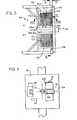
- the control cab or control station 42 takes the form of a hollow compartment or chamber 129 (Fig. 12) within which an operator may sit on a seat 130 at a location to actuate controls 131.
- the operator can view torque wrench 41 and a pipe engaged thereby through a transparent window 132 located in the lower front portion of the cab. He'also can view other portions of the mechanism through windows 133 in the upper portion of the cab, and can view video monitors 134 located within the cab and receiving signals from three video cameras 135, 136 and 137.
- Cameras 135 and 137 are carried by and nove with the upper and lower pipe holding units 38 and 39 respectively and are aimed toward units 38 and 39 and any pipe held thereby in all positions of units 38 and 39, and produce pictures of the units and pipe on the corresponding monitors.
- Camera 136 is carried by and moves with column 31 and aimed to view the underside of the racking board and pipes held in one of the sides thereof when the column and cab are turned to face laterally toward that side of the racking board as represented in Fig. 5.
- Cab 42 is rigidly attached to and located above the third vertically movable carriage 34, which has rollers 138 engaging the rear sides of tracks 50a and rollers 139 engaging the front sides of those tracks to guide the lower carriage 34 and cab for only upward and downward movement along the tracks.
- Torque wrench 41 is also attached to carriage 34, at a location beneath the cab, for movement upwardly and downwardly with the carriage and cab.
- This torque wrench may be of essentially conventional construction, including an upper section 140 for engaging an upper one of two interconnected pipe joint ends, and a lower section 141 for engaging the lower of the two connected joint ends.
- the upper section 140 includes two gripping jaws 142 which are connected pivotally together at 143 for actuation of their left ends as viewed in Fig. 17 toward and away from one another and between the broken line pipe gripping position of that figure and the full line open position.
- a piston and cylinder mechanism 144 received between the right ends of the jaw levers power actuates the jaws between their gripping and released conditions.
- the lower section 141 of the torque wrench is essentially the same as upper section 140, as discussed above, including two jaws similar to jaws 142 of Fi g . 7 and actuable between gripping and released conditions by a second piston and cylinder mechanism 145.
- the upper section 140 of the torque wrench grips the lower end of one pipe section and the lower section 141 of the torque wrench engages the upper end of a second pipe section.
- the torque wrench includes two additional piston and cylinder mechanisms 146 and 147, one of which has its cylinder connected to upper section 140 of the torque wrench and its piston connected to the lower section 141 of the torque wrench, and the other of which has its cylinder and piston connected in reverse to the two sections of the torque wrench, so that the piston and cylinder mechanisms 146 and 147 can power rotate the two sections of the torque wrench in either direction relative to one another and about the axis of the gripped pipe.
- the two sections 140 and 141 of the torque wrench are of course appropriately connected to the body of carriage 34 in a manner retaining them against vertical movement relative to the carriage and against horizontal displacement relative thereto from positions in which their gripping jaws are properly aligned with the vertical axis of spinner 40.
- Carriage 34, cab 42 and torque wrench 41 are connected to the upper two carriages 32 and 33 by a vertically extending piston and cylinder mechanism 148 whose cylinder is rigidly attached to carriage 33 and whose piston rod 149 is connected at 150 to the upper end of the cab.
- This attachment allows the cab and torque wrench to move upwardly and downwardly with the upper parallelogram mechanism and related parts, and to also be actuable upwardly and downwardly by piston and cylinder mechanism 148 relative to carriage 33, carriage 32 and the paralleogram mechanism.
- the purpose of this relative vertical movement of the cab and torque wrench is to allow the torque wrench to be adjusted easily to a proper position for effective engagement with two connected joint ends to make or break a connection therebetween.
- the lower pipe holding unit 39 is adapted to tightly grip pipe stand 23 in a manner both retaining it against rotation and supporting the pipe unit for lifting movement by unit 39.
- jaws 118 of unit 39 have gripping dies 218 with shoulders extending both vertically and horizontally to restrain rotary movement of the pipe and also support the weight of the entire pipe stand from unit 39.
- the two jaws 118 of the unit 39 are elongated and have their inner ends connected at 149 and 150 to the body 117 of unit 39 for swinging movement about two parallel vertical axes 153 between the full line gripping positions of Fig. 9 and the broken line open positions of that figure.
- the piston of a piston and cylinder mechanism 152 whose cylinder is rigidly attached to body 117 actuates a member 154 along a horizontal axis 155, with that member 154 being pivotally connected at 156 and 157 to two links 158, which are in turn pivotally connected at 159 and 160 to arms or jaws 118, in a relation swinging the jaws toward and away from one another in response to axial movement of the piston within unit 152.
- Rod 114 and the connected parts hold body 117 in a position in which the axes of pivotal connections 153 of jaws 118 extend directly vertically, and the axis 120 of gripping jaws 118 and of a pipe held thereby is directly vertical and aligned with axis 119 of the upper pipe holding unit and the axes of spinner 40 and torque wrench 41 in the Figs. 1 and 7 inner position of arms 36 and 37.
- the upper pipe holding unit 38 (Fig. 8) is in some respects similar to the lower unit 39, but serves only to locate or center the engaged portion of the pipe while not preventing rotation thereof.
- Unit 38 has two arms 161 connected pivotally at 162 to the body 118' of the unit 38 and to the cylinder of a piston and cylinder mechanism 163, to mount the arms for openino and closing movement between the full line and broken line positions of Fig. E.
- a member 164 actuated by the piston of cylinder 163 is pivotally connected at 165 to a pair of links 166 whose opposite ends are pivoted at 167 to arms 161 to open and close the arms upon axial movement of the piston.
- jaw arms 161 carry rollers 168 which engage the pipe and turn about vertical axes parallel to the axis of the pipe to enable free rotation of the pipe about axis 119.
- rollers 168 engage and closely confine the pipe to maintain it in centered directly vertically extending condition with respect to axis 119, while in the open position of arms 161 the rollers are far enough apart to allow the pipe holding unit to move onto and off of the pipe.
- the racking board 24 is in some respects of conventional construction, including two structures 169 and 170 at opposite sides of the central portion 76 of the racking board, with each of those structures 169 and 170 having a series of parallel horizontal fingers 171 spaced apart far enough to receive within the guideway 172 formed between each pair of successive fingers the upper ends of a row of pipe stands.
- the passages or guideways 172 between the various fingers have their longitudinal axes 173 extending directly perpendicular to the previously mentioned radial plane 54 which contains the axes 61 and 79 of the synchronized lower and upper lead screw actuating mechanisms defining the direction of retracting movement of the column structure and a carried pipe.
- the pipes are retained within the guideways or passaaes 172 by two series of segmentally formed bars 174 (Figs. 3 and 20), with these bars being actuated by two motors 175 and 176 under the control of the operator.
- motor 175 drives a horizontal shaft 177 through a reduction gear assembly 178, and about that shaft there are located a series of sprocket like wheels 179 each having four projections 180 at evenly circularly spaced locations as seen in Fi g . 20.
- Each bar 174 includes an articulated series of links 181 connected pivotally together at 182, with each link containing an opening adapted to receive one of the projections 180 of a corresponding one of the sprocket wheels 179 so that rotation of the sprocket wheels acts to advance the articulated bar longitudinally across the various pipe receiving guideway recesses or passages 172 of a corresponding one of the racking board sections 169 or 170.
- all but an end one or two of the links of that bar hang downwardly as represented at 183 in Fig. 20.
- the links move successively to the left in the upper portion of Fig.
- Each of the sprocket wheels 179 is rotatable about shaft 177, and can be releasably keyed to the shaft for rotation therewith by actuation of an individual clutch 184 associated with the sprocket wheel, and be retained against rotation by a brake 185.
- An operator in the control cab can actuate any one of the clutches to cause advancement of any of the bars for retaining a corresponding one of the stored pipes in the rack, and upon release of the clutch the associated brake 185 acts to automatically lock the bar in that setting until subsequently actuated again for retention of another pipe in a next successive one of the pipe racking recesses 172.
- the pipe receiving guideways 172a at the left ends of the two sections 169 and 170 of the racking board assembly as viewed in Fig. 3 are wider than the other guideways, to receive drill collars which are of greater diameter than the other pipe sections of a drill string.
- only alternate ones of the bars 174 are utilized to extend across guideways 172a, with these bars being engageable at the end of their travel with gate members 186 pivoted at 187 for swinging movement between the full line inactive position of Fig. 20 and the broken line active position of extension across the guideway.
- the end segment of the bar engages the right side of element 186 as viewed in Fig. 20, and deflects that element to its broken line position.
- Intermediate ones of the bars do not have a gate element 186 associated therewith, to thus leave spaces wide enough for reception of the increased diameter drill collar sections.
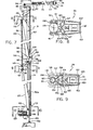
- the remotely controlled elevator 25 (Figs. 18 and 19) includes a rigid body 188 adapted to extend entirely about a pipe stand and having loops 189 at diammetrically opposite locations for engagement with the suspending links 26 in a manner holding the body of the device with its axis 190 in a directly vertical condition.
- Four slips 191 are contained within the body at circularly spaced locations, and are actuable vertically between the broken line retracted position of Fig. 19 and the full line active position of that figure.
- the slips are retracted upwardly and radially outwardly far enough to allow the tool joints of a pipe string to move upwardly and downwardly through the elevator, while in the active full line position of the slips, their inclined upwardly facing inner surfaces 192 are engageable with the downwardly facing inclined shoulder surfaces 193 on the tool joints to support a stand of the pipe string from the elevator.
- a lower throat 194 in the body of the elevator assists in stabbing the elevator relative to the upper end of a section of pipe.
- each piston and cylinder mechanism 195 at diammetrically opposite sides of the elevator body 188 actuate the slips upwardly and downwardly between their gripping and released positions.
- the cylinder 196 of each piston and cylinder mechanism 195 is formed as a portion of a member 197 containing two latch elements 198 which connect the associated slips to member 197 for movement upwardly and downwardly therewith.
- Each element 198 has a cylindrical shank 199 received slidably within a radially extending passageway 200 in member 197 and guided thereby for movement radially inwardly and outwardly with respect to the vertical axis 190 of the elevator.
- each piston and cylinder mechanism 195 may be double-ended and connect at both its upper and lower ends to ears 207 of body 188.
- the axis 208 of the piston and cylinder mechanism extends vertically and parallel to axis 190 to attain the desired upward and downward actuation of the slips.
- Figs. 22 through 24 show the machine 10 as it appears when utilized for assisting in the lowering of a string of casing 220 into a well 18.
- the machine functions to hold a section of casing 220a in vertical alignment with the upper ends 221 of the casing string already in the hole, and rotates section 220a to screw its lower externally threaded end 222 into the upper internally threaded box end 223 of the string.
- the column structure 31 and carried parts are retracted a short distance to the right of their Fig. 1 position, so that the upper drill pipe holding unit 38 and torque wrench 41 are retracted far enough to the right to avoid contact with the casing.
- two jaws 224 are rigidly attached to the jaws 118 of unit 39 of the machine, and project leftwardly therebeyond as viewed in Figs. 22 and 23. These jaws 224 may be attached to jaws 118 in any convenient manner, as by fasteners represented diagrammatically at 225, to be actuable with the jaws 118 by piston and cylinder mechanism 152 between the full line casing gripping condition of Fig. 23 and the broken line open condition of that figure.
- Jaws 224 have inner cylindrically curved complementary surfaces 226 which are curved in correspondence with the outer surface of casing section 220a and are adapted to grip the casing in a manner locating it against horizontal movement while at the same time permitting rotation of the casing relative to jaws 224, and also permitting vertical movement of the casing relative to those jaws.
- Tong 227 may be of known conventional construction including a body 230 formed of a main section 231 and two outer jaws 232 connected to body 231 pivotally at 331 for swinging movement relative thereto between the closed full line positions of Fig.
- gripping elements 234 of the tong engage and arip the casing and rotate it about the vertical axis 17 of the casinq to make or break a threaded connection at its lower end when the gripping elements are driven rotatively about axis 17 by a remotely controlled motor represented at 235.
- Jaws 231 may be opened and closed by piston and cylinder mechanisms 233, and may be releasably locked in closed condition by a latch mechanism 236 operated by a piston and cylinder mechanism 336.
- the casing stand is suspended and lowered into engagement with the upper box end 221 of the casing string by an elevator 237 suspended from the traveling block 27.
- the pipe holding units 38 and 39 have their axes directly vertically aligned with the axes of spinner 40 and torque wrench 41, so that all of these units are located for simultaneous engagement with a stand of pipe when the column structure is actuated inwardly to the full line position of Fig. 1.
- elevator 25 is lowered downwardly about the upper end of the upper stand of pipe, and the slips of the elevator are actuated downwardly under the remote control of the drawworks operator actuating a valve 209 for delivering pressurized fluid to the cylinders of the elevator to move their slips downwardly.
- the slips are then in condition to grip the drill pipe and enable the elevator to lift the string to tie Fig. 1 position.
- slip assembly 15 can be set to engage the string just beneath the upper three section stand and support the string in the well.
- the elevator may then be remotely released and pulled upwardly away from the string, after which the operator actuates a switch 210 in cab 42 to energize motors 63 and 80 simultaneously and in unison to move the upper and lower ends of the column structure 31 leftwardly in precisely synchronized relation, and to the full line position of Fig. 1, in which the column structure remains directly vertical and the various vertically aligned units 38, 39, 40 and 41 are all received about the pipe stand.
- the jaws are of course all fully opened during such leftward movement of the column structure and carried parts to enable the different units 38, 39, 40 and 41 to thus move about the pipe.
- the leftward end of the horizontal stroke of the column structure is precisely determined to accurately locate units 38, 39, 40 and 41 at exactly at the well center line, with a stop limiting leftward movement in that position and thus avoiding any requirement for precise control of the positioning of the column by the operator.
- the operator By actuation of another switch or valve 211 in the control cab, the operator actuates piston and cylinder mechanism 148 to move the cab and torque wrench upwardly or downwardly as necessary to bring the upper and lower sections of the torque wrench into proper engagement with the lower end of one pipe section and the upper end of another pipe section. If necessary, this movement may be supplemented by actuation of piston and cylinder mechanism the column structure.
- the operator then actuates an additional control valve or switch 212 in the cab to close the jaws of the torque wrench 41 and cause the torque wrench to forcibly rotate the joint end engaged by its upper section in a counterclockwise direction relative to the connected joint end engaged by its lower section in order to break the threaded connection at that location.
- the torque wrench may then be opened after which the jaws of spinner 48 may be closed and the motors of that spinner actuated by operation of another switch or switches 213 in the cab to cause the spinner to grip and rapidly rotate stand 23 relative to the remainder of the string to complete the disconnection of that stand from the string.
- the operator actuates another switch or valve 214 in the cab to close the jaws of upper pipe holding unit 38 in a manner enabling that unit to locate the upper portion of the stand and hold it in proper position while the spinner unscrews it from the upper end of the string.
- the operator actuates another valve or switch 215 in the cab to close the jaws of the lower pipe holding unit 39 tightly enough on the stand to lift the stand, with vertical movement thereof being attained by actuating piston and cylinder mechanism 127 to pull the various carriages 32, 33 and 34 and connected parts upwardly far enough to move the lower end of the stand completely out of the upper box end of the remainder of the drill string.
- the operator actuates a switch or valve 216 in the cab to energize rotary drive 45 at the bottom the column structure, and pivot the column and the carried parts including the suspended stand 23 through 90° about axis 46, to thus swing the stand to one side of the central portion 76 of the racking board assembly 24, as from the position represented at 23a in Fig. 3 to the position represented at 23b in that figure.
- the rightward travel of the column structure and carried parts is continued beyond the position 23b of the stand and until the stand reaches a position opposite a particular one of the pipe receiving guideways 172 in the racking board assembly within which that particular stand is to be located.
- a first stand would normally be moved to a location opposite the guideway 172 which is located to the extreme right in Fi g . 3, as to the position represented at 23c in that figure.
- the operator then releases the spinner and actuates a switch or valve 217 in the cab causing delivery of pressure fluid to piston and cylinder mechanism 94 acting to swing arms 36 and 37 and the two pipe holding units 38 and 39 and the stand supported thereby from the broken line position of Fig. 5 to a position such as that represented in full lines in that figure.
- the pipe moves downwardly as it moves laterally, and this movement continues until the stand reaches the end of the guideway 172 or contacts a previously inserted stand in that same guideway.
- the operator actuates a control 218 in the cab to actuate one of the motors 175 or 176 and one of the clutch and brake assemblies 184-1S5 to move one of the bars 174 far enough to cross that particular guideway 172 and lock the stand in position in that guideway.
- the operator actuates piston and cylinder mechanism 127 to lower carriages 32, 33 and 34 and the stand until the stand engages the rig floor.
- the pipe holding units 38 and 39 are then opened remotely by the operator, piston and cylinder mechanism 94 is actuated to swing the arms to their retracted positions in which the movement is limited by the locating stops, and the machine is brought back to the stand-by position by shifting the column leftwardly and pivoting the column structure about axis 46. The procedure can then be repeated for each succeeding stand until all of them have been stored in the racking board assembly.
- the procedure for returning the string back into the well is in mcst respects the reverse of that discussed above.
- the machine is first lined up with a selected one of the guideways 172 of the racking board assembly, and the arms 36 and 37 are then extended until pipe holding units 38 and 39 contact the stand and stop. These holding units are then closed and clamped about the stand, and the stand is raised off of the floor by elevation of the carriaaes and connected mechanism relative to the column structure.
- the arms and carried pipe stand are then swung to the fully retracted position, the torque wrench is vertically adjusted to a position in which its upper section engages the lower pin end of the stand, and the spinner is clamped on the stand.
- the am- chine is shifted horizontally as far as the stand-by position and rotated through 90° toward the well center line, where it may wait if the string is not yet in proper position for reception of the stand.
- the operator can move column structure 31 and the supported stand to the well center line above the upper end of the drill string, after which the carriages 32, 33 and 34 can be lowered to move the stand downwardly into engagement with the upper end of the string, so that the spinner 40 can advance the stand rotatably into the upper box end of the string, and torque wrench 41 can be actuated to make up the connection tightly.
- An automatic interlock represented diagrammatically at 219 between the lower pipe holding unit 39 and spinner 49 acts to automatically release unit 39 from its clamped condition of engagement with the pipe stand when the spinner is energized, to thus allow the spinner to turn the pipe.
- the upper pipe holding unit 38 assists in locating the pipe during the spinning and torqueing operation.
- the operator can engage elevator 25 with the upper end of the added stand, and with all of the jaws of units 38, 39, 40 and 41 opened, column structure 31 and the carried parts can be retracted to the stand-by position and then shifted pivotally and horizontally to a position for picking up the next successive stand from the racking board assembly.
- jaws 224 are connected to pipe holding unit 39 in the relation illustrated in Figs. 22 and 23, spinner 40 is removed from carriage 33, and the power driven casing tong 227 is attached to carriage 33.
- the column structure 31 is retracted rightwardly a short distance from the Fig. 1 position and to the position of Fig. 22 in which the casing gripping portions of jaws 224 and casing tong 227 are centered about and aligned with vertical axis 17 of the well.
- Jaws 224 may be opened to their broken line position of Fig.
- gripping elements 234 of casing tonq 227 may be retracted radially outwardly to their open positions in which elevator 237 and a suspended stand 220a of casing may be lowered along axis 236 and downwardly into the casing tong 227 to a position such as that represented in Fig. 22. Jaws 224 may then be closed to grip the casing sufficiently tightly to effectively and positively locate it against horizontal movement while at the same time allowing rotary and vertical movement of the casing in that centered position.
- the actuating motor or mechanism 235 of the casing tong is then energized by the operator in cab 42 to tightly grip the casing section 220a and rotate it for connection of its lower threaded end 222 to box end 221 of the casing string.
- the tong may be adapted to allow downward movement of the casing section during completion of this threaded connection, to allow the threads 222 to advance into box 221. It is also contemplated that if desirable the carriage 33 may be lowered with the casino stand during completion of the threaded connection.
Abstract
Description
- This invention relates to machines for assisting in connecting a series of pipe stands to or disconnecting then from the upper end of a string of well pipe.
- When it becomes necessary during the drilling of a well to remove the entire drill string from the well, in order to replace a bit at the lower end of the string or for other reasons, the various stands which make up the string are sequentially detached from the upper end of the string and temporarily stored in a rack in a side of the derrick. After the bit has been replaced or another desired operation has been performed, the stands are sequentially removed from the rack and returned into the hole. This round trip procedure requires the presence of several men on the rig floor for making and breaking connections and moving the pipe stands, and also requires a derrickman at an elevated location in the rig for controlling the pipe at that location and moving the upper ends of the pipe stands into and out of the racking board. In addition to the expense involved, the round tripping procedure is dangerous to all of the men on the rig, and very time consuming. There have been attempts in the past to mechanize some of the steps involved in handling the pipe during a round trip, but none of these prior expedients has to my knowledge proven effective or practical enough for any wide scale adoption in the actual drilling of wells.
- The general purpose of the present invention is to provide an improved pipe handling machine which can be utilized in a conventional drilling rig with a standard derrick structure and which can perform all of the pipe handling and racking operations during a round trip with fewer persons on the rig, preferably a single operator, and desirably with no manual pipe handling steps. The machine can function under the control of a single operator to make and break threaded connections and move each stand very positively between a position of alignment with the well axis and a storage location. The, machine can handle stands of both drill pipe and drill collars, and can also be utilized for handling casing.
- A machine embodying the invention includes a support which preferably takes the form of a vertically extending column and which carries means for holding a pipe in vertically extending condition, and which is bodily shiftable to move the pipe from the location of the well axis to a laterally offset position near a storage rack. The pipe holding means desirably include two pipe holding units at vertically spaced locations for engaging and gripping the pipe at those spaced locations to very positively locate and control the movements of the pipe. Two synchronized drive mechanisms may engage the column at vertically spaced locations, preferably at the upper and lower ends of that structure,and be operable to move those portions in unison with one another in a manner effecting the desired horizontal bodily shifting movement of the column and carried parts while continuously maintaining the supported pipe in vertical condition.
- In the retracted position offset to a side of the well axis, the pipe holding units and carried pipe stand may be shiftable laterally relative to the column structure to move the pipe to a racked position. For this purpose, the synchronized drive mechanisms desirably include pivotal connections mounting the column to pivot about a vertical axis in order to face in a proper direction for movement of the pipe stand into a racking board. The pipe holding units may be moved horizontally in correspondence with one another relative to the column to perform the racking and unracking function. This generally horizontal movement of the pipe holding units and carried pipe may be attained by connecting the units to the column through a parallelogram machanism having swinging arms mounting the two units respectively and swinging together toward and away from the column and relative to the racking board.
- In order to allow the pipe to be raised and lowered relative to the string and the rig floor and other portions of the rig, the pipe holding means may be mounted to a carriage structure which is shiftable upwardly and downwardly relative to the main column structure or support of the apparatus. The machine may also include a spinner and torque wrench for making and breaking connections between the pipe string and a stand being connected to or detached from the string. These elements are preferably shiftable upwardly and downwardly with the carriage and pipe holding units, and the torque wrench may also be movable upwardly and downwardly relative to the spinner and other parts of the apparatus. In order to facilitate control of the apparatus, the machine may include a control station in the form of a cab adapted to contain or support an operator and having control equipment for actuating the various movable parts of the apparatus. This control station may be mounted for movement upwardly and downwardly relative to the supporting column and with the pipe holding units and other elements, and preferably also for pivotal movement with the various pipe supporting parts and other related elements to properly face the racking board during movement of a pipe into or out of the rack.
- The above and other features and objects of the invention will be better understood from the following detailed description of the typical embodiment illustrated in the accompanying drawings, in which:
- Fig. 1 is a side view of a well pipe handling machine embodying the invention shown in a position of engagement with the upper end of a drill string in a drilling rig;
- Fig. 2 is a front view of the machine taken on line 2-2 of Fig. 1;
- Fig. 3 is an enlarged fragmentary plan view of the pipe racking board area taken on line 3-3 of Fig. 1;
- Fig. 4 is a somewhat diagrammatic representation of the rig floor, taken on line 4-4 of Fig. 1;
- Fig. 5 is a view which may be considered as taken essentially on line 5-5 of Fig. 3, and showing the machine in a position for racking a pipe in that plane;
- Fig. 6 is an enlarged fragmentary rear elevational view of the machine taken on line 6-6 of Fig. 1;
- Fig. 7 is a fragmentary vertical sectional view taken primarily on line 7-7 of Fig. 6;
- Figs. 8, 9 and 10 are plan views of the upper and lower pipe holding units and the spinning wrench taken on lines 8-8, 9-9 and 10-10 respectively of Fig. 7;
- Fig. 11 is a vertical section taken on line 11-11 of Fig. 7;
- Fig. 12 is an enlarged fragmentary exploded view of the lower portion of the machine taken on line 12-12 of Fig. 1;
- Fig. 13 is a fragmentary vertical section taken primarily on line 13-13 of Fig. 12;
- Fig. 14 is a view taken on line 14-14 of Fig. 13;
- Fig. 15 is a fragmentary rear elevational view taken on line 15-15 of Fig. 13;
- Fig. 16 is a fragmentary vertical section taken on line 16-16 of Fig. 14;
- Fig. 17 is a horizontal section taken on line 17-17 of Fig. 13;
- Fig. 18 is an enlarged top plan view of the remotely controlled elevator taken on line 18-18 of Fig. 1;
- Fig. 19 is a partially elevational and partially sectional view of the elevator taken on line 19-19 of Fig. 18;
- Figs. 20 and 21 are enlarged fragmentary vertical sections taken on lines 20-20 and 21-21 respectively of Fig. 3;
- Fig. 22 is a fragmentary view similar to Fig. 1, but showing the machine as utilized for running a string of casing into the well; and
- Figs. 23 and 24 are enlarged horizontal sectional views taken on lines 23-23 and 24-24 respectively of Fig. 22.
- There is illustrated at 10 in Fig. 1 a well pipe handling machine constructed in accordance with the invention and shown positioned within a somewhat diagrammatically represented drilling rig 11 including a
derrick 12 having arig floor 13 containing anopening 14 within which aslip assembly 15 is receivable for releasably supporting adrill string 16 extending along avertical axis 17 and downwardly into awell 18. The rig is typically illustrated as a conventional arrangement in which theslip supporting opening 14 is contained within a rotary table 19 which turns the string during a drilling operation. It will be understood, however, that the machine may also be utilized in a top drive system in which a motor connected to the upper end of the string drives it rotatively and is movable upwardly and downwardly with the string during drilling. The drill string is formed in conventional manner of a series ofpipe sections 20 each having a lower externally threadedpin end 21 connected to an upper internally threadedbox end 22 of the next successive section. During a round trip of the string out of and then back into the well, the string is broken into a series ofstands 23 each including three of theinterconnected pipe sections 20, with these stands being moved by themachine 10 from the center line position ofstand 23 in Fig. 1 to storage positions within aracking board assembly 24. The pipe string is raised and lowered by a remotely controlledelevator 25 suspended bylinks 26 from atraveling block 27, which in turn is suspended on aline 28 from acrown block 29 attached to the top of the derrick, with the line being actuable by drawworks 30 to move the elevator upwardly and downwardly. - The moving parts of
machine 10 are carried principally by avertical column structure 31 to which threecarriages parallelogram mechanism 35 having upper andlower arms clamping unit 38 and a lower pipe holding orclamping unit 39. Carriage 33 also mounts aspinner 40 for turning the pipe rapidly, and thelower carriage 34 supports atorque wrench 41 and a control cab orstation 42 within which the single operator of the machine is located. Thecolumn structure 31 is movably supported at its lower end on a base 42'connected torig floor 13, and is connected movably at its upper end to rackingboard 24. Two synchronized drives 43 (Fig. 7) and 44 (Fig. 13) move the upper and lower ends of the column structure leftwardly and rightwardly in unison as viewed in Fig. 1, and a rotary drive 45 (Fig. 13) at the lower end of the column structure control- lably pivots it about avertical axis 46. -
Column structure 31 is a rigid vertical framework including two similar spaced parallelvertical column elements 47 joined together at their upper ends by ahorizontal connector member 48 welded or otherwise secured toelements 47, and secured together at their lower ends by ahorizontal connector member 49 also appropriately rigidly secured toelements 47.Elements 47 may have the hollow rectangular configuration illustrated in Fig. 10 along the entire vertical extent ofelements 47. At their inner sides,elements 47 rigidly carry an upper pair of vertical track orrail elements 50, and a similar lower pair of track orrail elements 50a, to guide thevarious carriages track members - The base 42'on which
column structure 31 is mounted (Figs. 12 and 13) is a rigid structure appropriately bolted or otherwise secured in fixed position on therig floor 13, and typically including twoparallel side beams 51 acting as load support beams and carrying ahorizontal top plate 52 extending across the upper side of base 42', with two parallelhorizontal tracks 53 being welded, bolted or otherwise secured toplate 52 andbeams 51.Tracks 53 are located at opposite sides of and equidistant from, and extend parallel to, a vertical plane 54 (Fig. 14) which contains the mainvertical axis 17 of the well and extends radially with respect thereto. Acarriage 55 is movable horizontally alongtracks 53 and radially with respect towell axis 17, and may include upper and lowerrigid plates vertical connectors 58 extending between and securing together theplates wheels 59 mounted rotatably to the body of the carriage at its underside. These wheels engage the twotracks 53 and roll along it, and haveannular flanges 60 at their opposite sides engageable with opposite sides of the tracks to effectively retain the wheels on the tracks and thus guide the carriage for only straight line horizontal movement along an axis 61 extending perpendicular to and intersectinawell axis 17. The carriage is power actuable along this axis and further guided by alead screw 62 connected rotatably to base 42 at its upper side to turn about axis 61. Amotor 63 drives screw 62 in opposite directions through aworm gear transmission 64, and inherently brakes the screw in any setting to which it may be turned and so long as the motor is not energized. Anut 65 engages the screw and is actuated axially thereby upon powered rotation of the screw, and is attached tocarriage 55 at 65, to thus move the carriage horizontally along axis 61 when the motor is energized. - The lower end of
column structure 31 is connected pivotally tocarriage 55 by reception of a downwardly projectingpivot pin 66 carried by a lowerhorizontal element 49 of the column structure within acentral openina 167 in apinion gear 67 mounted on the carraige for rotation relative thereto aboutvertical axis 46. This pinion gear is journalled for such rotation by bearings represented at 68, and is retained against rotation relative to pin 66 by a key 166 to positively turncolumn structure 31 aboutaxis 46 upon rotation of the pinion gear. Atoothed rack 69 engagespinion 67 and is actuable along ahorizontal axis 70 by one or more piston and cylinder mechanisms represented at 71 to turn the pinion gear andconnected column structure 31 aboutaxis 46 in response to the delivery of pressure fluid to the piston andcylinder mechanisms 71. The column structure can thus be moved pivotally aboutaxis 46 by the hydraulic rotary rack and pinion actuator 67-69, and be moved toward and away from the main axis of the well bymotor 63. The weight of the column structure is supported oncarriage 55 by a thrust bearing represented at 72, and is transmitted from the carriage to base 42' bywheels 59 and tracks 53. The carriage structure and carried parts may be locked in the position of Fig. 1 by insertion of a cylindrical locking pin 73 (Fig. 12) downwardly through avertical passage 74 inhorizontal bottom member 49 of the column structure and through a registeringopening 75 formed incarriage 55. In this Fig. 1 position, the various pipe holding and actuatingelements vertical axis 17 of the well, to hold and drive a pipe extending vertically along that axis.Rotary actuator 45 consisting ofpinion 67,rack 69 andpower cylinders 71 can turn the column structure through exactly 90° in either direction from the Fig. 1 position, with the pivotal motion being positively limited by engagement of appropriate stop shoulders on the pivotally connected parts in those extreme 90° positions, to properly locate the pipe holding units for movement of a carried pipe into and out of storage locations in the racking board, as will be discussed in greater detail at a later point. - The upper end of the
column structure 31 is mounted by a powered straight line drive mechanism which is synchronized to the straight line drive at the lower end cf the column, to move the upper and lower ends in unison at all times, and thus maintain the column structure and a pipe held thereby continuously in directly vertical condition. More specifically, the drive structure at the upper end of the column may be mounted to the underside of acentral portion 76 of rackingboard 24 and include alead screw 77 mounted toportion 76 bybearings 78 for rotation about ahorizontal axis 79 extending parallel to the axis 61 oflower screw 62 and intersectingaxes motor 80 drives screw 77 aboutaxis 79 through a self-brakingworm gear transmission 81, to actuate a nut 82 axially upon rotation of the motor in either of two opposite directions. Nut 82 is in turn connected rigidly to the upper side of a structure 83 which carries avertical pivot pin 84 centered aboutaxis 46 and aligned vertically withlower pivot pin 66. Thispin 84 is closely received and journalled within openings in a pair of bearingplates 85 attached to the upper end of the column structure, to thus locate the upper end of the column structure for pivotal movement about the same axis as the lower end of that structure. The structure 83 which carriespivot pin 84 may include ahorizontal plate 86 carrying two pairs ofrollers 87 at its upper side mounted for rotation about spacedvertical axes 187 and engaging two parallel horizontally extendingguide tubes 88 attached rigidly tomember 76 of the racking board assembly.Tubes 88 may have the square vertical cross-sectional configuration illustrated in Fig. 11, to project into annular grooves in therollers 87, in a manner effectively guiding structure 83 andpivot pin 84 and the upper end of the column structure for movement only alongaxis 79 ofscrew 77.Motors - The upper vertically
movable carriage 32 has an upper pair of rollers 89 (rig. 6) engaging the back sides of the twotrack elements 50, and has a second pair ofrollers 90 engaging the front sides oftracks 50 to effectively guide the carriage for only up and down movement relative to and alongcolumn structure 31, and parallel to the verticalpivotal axis 46.Carriage 32 may be fabricated of a number of parts welded to- gether, typically including aplate 91, and twomembers 92 which carryrollers 89 rotatably and converge toward one another for pivotal connection at 93 to the piston of a piston andcylinder mechanism 94 whose cylinder is pivoted toarm 36 at 95. The axes of thepivotal connections -
Arm 36 is an elongated rigid structure which may taper to a reduced width as shown and may be formed of metal plates welded together in the configuration illustrated. The inner end of the arm includes a pair of generally parallel side plates 96 (Fig. 6) rigidly secured together by across member 97 which is typically of rectangular configuration as illustrated in Fig. 7. Thepivotal connections 95 between the cylinder of piston andcylinder mechanism 94 andarm 36 may be attached toside plates 96 of the inner portion of the arn. A bearinglug 98 may project fromcross piece 97 of the arm and be connected pivotally at 193 to lower portions of themembers 92 ofcarriage 32, with the axis 99 of that pivotal connection being horizontal and parallel to the axes ofrollers pivotal connections Rollers 90 may be mounted to the inner end ofarm 36, by rotary attachment of the lower extremities ofside plates 96 of the arm.Rollers 90 thus serve a dual purpose of coacting withupper rollers 89 in guiding the carriage and arm for upward and downward movement and also mountingarm 36 for pivotal movement about the horizontal axis 100 ofrollers 90. - The second vertically
movable carriage 33 may include a vertical plate 101 (Figs. 6 and 7) carrying twoparallel side plates 102 to which there are rotatably mounted an upper pair ofrollers 103 turning about a horizontal axis 104 and engaging the rear sides oftracks 50a and a lower pair ofrollers 105 turning about a parallelhorizontal axis 106 and engaging front sides of thetracks 50a.Arm 37 may be fabricated of metal plates as discussed in connection witharm 36 and include two spacedplates 108 at the inner end of the arm connected pivotally bybearings 109 toside plates 102 of the carriage, to mountarm 37 for swinging movement about ahorizontal axis 110 extending parallel to and spaced beneath and vertically aligned with the horizontal axis 100 about whichupper arm 36 swings. The twoarms parallelogram mechanism 35 which functions to cause the arms to swing exactly in unison with one another and at all times be positioned at exactly the same angle to the vertical.Carriages members 92 ofcarriage 32 by abolt 112 and at its lower end to plate 101 ofcarriage 33 by abolt 113. This arm thus forms a third side of the parallelogram mechanism, with the fourth side being formed by another rigidvertical rod 114 attached at its lower end by aconnection 115 topipe holding unit 39, and attached at its upper end by apivotal connection 116 to the extremity ofarm 36. Thebody 117 ofpipe holding unit 39 may be rigidly attached to the lower end ofrod 114 so that the rod will always maintainunit 39 in directly horizontal condition, with the axis of the grippingjaws 118 ofunit 39 in vertical condition, and similarly the upper end ofrod 114 may be connected rigidly to a body 118' of upperpipe holding unit 38 to maintain that unit in directly horizontal condition and parallel to lowerunit 39, with thegripping axis 119 ofunit 33 extending vertically and aligned with thegripping aixs 120 oflower unit 39.Unit 39 is pivotally connected at its underside to the extremity ofarm 37 by a connection represented at 121. The distance betweenaxes lower arm 37 is exactly equal to the distance between thepivotal axes 100 and 116 at the opposite ends ofarms 36, and the effective length of the structure extending vertically betweenpivotal connections rod 114 and the body of lowergripping unit 39 is exactly equal to the effective length of thestructure connecting carriages - In addition to functioning as the pivotal mounting for
lower arm 37,carriage 33 also acts as the support for spinningwrench 40. This wrench may be of essentially conventional construction, including abody 121 rigidly but preferably removably attached tocarriage 33, and typically illustrated as supported on abottom plate 202 of the carriage and secured thereto by fasteners represented at 228.Body 121 of the spinner carries twoinner rollers 122 and twoouter rollers 123 turning about four parallelvertical axes 222 and driven about those axes byindividual motors 240 operating in unison with one another. The twoinner rollers 122 may be fixed at locations to engage the inner side of a well pipe stand 23 and the twoouter rollers 123 may be mounted toarms 224 connected pivotally at 125 tobody 121 of the spinner for swinging movement toward and away from one another between the open full line positions of Fig. 10 and the closed broken line positions of that figure. In the open positions ofrollers 123, those rollers are spaced apart a distance greater than the diameter of the pipe to be held, and can thus be moved onto and off of the pipe, while in the closed broken line positions of Fig. 10 all four of the rollers engage the pipe to effectively rotate it about the vertical axis of the pipe upon energization of the driving motors. Arms 124 and the carriedrollers 123 are actuable between their full line and broken line positions of Fig. 10 by piston andcylinder mechanisms 126 having their cylinders attached tobody 121 of the spinner and their pistons attached to the arms or levers 224. In the closed condition of the rollers, the axis of the spinner and of a pipe held and driven by the spinner is exactly aligned vertically with the axes ofpipe holding units units motors 240 can drive the rollers in opposite directions, to turn the pipe in a direction to either screw two pipe sections together or threadedly detach them. - The two
carriages cylinder mechanism 127, whose cylinder may be attached at its upper end to the top ofcolumn structure 31, and whose piston may be attached at 128 to plate 91 of the upper carriage. - The control cab or
control station 42 takes the form of a hollow compartment or chamber 129 (Fig. 12) within which an operator may sit on aseat 130 at a location to actuatecontrols 131. The operator can viewtorque wrench 41 and a pipe engaged thereby through atransparent window 132 located in the lower front portion of the cab. He'also can view other portions of the mechanism throughwindows 133 in the upper portion of the cab, and can view video monitors 134 located within the cab and receiving signals from threevideo cameras Cameras pipe holding units units units Camera 136 is carried by and moves withcolumn 31 and aimed to view the underside of the racking board and pipes held in one of the sides thereof when the column and cab are turned to face laterally toward that side of the racking board as represented in Fig. 5.Cab 42 is rigidly attached to and located above the third verticallymovable carriage 34, which hasrollers 138 engaging the rear sides oftracks 50a androllers 139 engaging the front sides of those tracks to guide thelower carriage 34 and cab for only upward and downward movement along the tracks.Torque wrench 41 is also attached tocarriage 34, at a location beneath the cab, for movement upwardly and downwardly with the carriage and cab. This torque wrench may be of essentially conventional construction, including anupper section 140 for engaging an upper one of two interconnected pipe joint ends, and alower section 141 for engaging the lower of the two connected joint ends. As seen in Fig. 17 theupper section 140 includes twogripping jaws 142 which are connected pivotally together at 143 for actuation of their left ends as viewed in Fig. 17 toward and away from one another and between the broken line pipe gripping position of that figure and the full line open position. A piston andcylinder mechanism 144 received between the right ends of the jaw levers power actuates the jaws between their gripping and released conditions. In their open conditions, the jaws are far enough apart to allow the torque wrench to move between a position about the pipe and a position laterally offset therefrom. Thelower section 141 of the torque wrench is essentially the same asupper section 140, as discussed above, including two jaws similar tojaws 142 of Fig. 7 and actuable between gripping and released conditions by a second piston andcylinder mechanism 145. After the torque wrench has been positioned at one of the joints of the pipe string, theupper section 140 of the torque wrench grips the lower end of one pipe section and thelower section 141 of the torque wrench engages the upper end of a second pipe section. The two sections of the torque wrench can then be turned relative to one another aboutaxis 17 of the pipes to either break or make a threaded connection between the pipes. To attain this relative rotation, the torque wrench includes two additional piston andcylinder mechanisms 146 and 147, one of which has its cylinder connected toupper section 140 of the torque wrench and its piston connected to thelower section 141 of the torque wrench, and the other of which has its cylinder and piston connected in reverse to the two sections of the torque wrench, so that the piston andcylinder mechanisms 146 and 147 can power rotate the two sections of the torque wrench in either direction relative to one another and about the axis of the gripped pipe. The twosections carriage 34 in a manner retaining them against vertical movement relative to the carriage and against horizontal displacement relative thereto from positions in which their gripping jaws are properly aligned with the vertical axis ofspinner 40. -
Carriage 34,cab 42 andtorque wrench 41 are connected to the upper twocarriages cylinder mechanism 148 whose cylinder is rigidly attached tocarriage 33 and whosepiston rod 149 is connected at 150 to the upper end of the cab. This attachment allows the cab and torque wrench to move upwardly and downwardly with the upper parallelogram mechanism and related parts, and to also be actuable upwardly and downwardly by piston andcylinder mechanism 148 relative tocarriage 33,carriage 32 and the paralleogram mechanism. The purpose of this relative vertical movement of the cab and torque wrench is to allow the torque wrench to be adjusted easily to a proper position for effective engagement with two connected joint ends to make or break a connection therebetween. - The lower
pipe holding unit 39 is adapted to tightly grip pipe stand 23 in a manner both retaining it against rotation and supporting the pipe unit for lifting movement byunit 39. For this purpose,jaws 118 ofunit 39 have gripping dies 218 with shoulders extending both vertically and horizontally to restrain rotary movement of the pipe and also support the weight of the entire pipe stand fromunit 39. The twojaws 118 of theunit 39 are elongated and have their inner ends connected at 149 and 150 to thebody 117 ofunit 39 for swinging movement about two parallelvertical axes 153 between the full line gripping positions of Fig. 9 and the broken line open positions of that figure. The piston of a piston andcylinder mechanism 152 whose cylinder is rigidly attached tobody 117 actuates amember 154 along ahorizontal axis 155, with thatmember 154 being pivotally connected at 156 and 157 to twolinks 158, which are in turn pivotally connected at 159 and 160 to arms orjaws 118, in a relation swinging the jaws toward and away from one another in response to axial movement of the piston withinunit 152.Rod 114 and the connected parts holdbody 117 in a position in which the axes ofpivotal connections 153 ofjaws 118 extend directly vertically, and theaxis 120 ofgripping jaws 118 and of a pipe held thereby is directly vertical and aligned withaxis 119 of the upper pipe holding unit and the axes ofspinner 40 andtorque wrench 41 in the Figs. 1 and 7 inner position ofarms - The upper pipe holding unit 38 (Fig. 8) is in some respects similar to the
lower unit 39, but serves only to locate or center the engaged portion of the pipe while not preventing rotation thereof.Unit 38 has twoarms 161 connected pivotally at 162 to the body 118' of theunit 38 and to the cylinder of a piston andcylinder mechanism 163, to mount the arms for openino and closing movement between the full line and broken line positions of Fig. E. A member 164 actuated by the piston ofcylinder 163 is pivotally connected at 165 to a pair oflinks 166 whose opposite ends are pivoted at 167 toarms 161 to open and close the arms upon axial movement of the piston. Instead of gripping dies,jaw arms 161 carryrollers 168 which engage the pipe and turn about vertical axes parallel to the axis of the pipe to enable free rotation of the pipe aboutaxis 119. In the closed position,rollers 168 engage and closely confine the pipe to maintain it in centered directly vertically extending condition with respect toaxis 119, while in the open position ofarms 161 the rollers are far enough apart to allow the pipe holding unit to move onto and off of the pipe. It will of course be understood that all of the pivotal and rotary axes in the linkages of Figs. 8 and 9 extend directly vertically and parallel to one another to attain the discussed type of operation. - The racking
board 24 is in some respects of conventional construction, including twostructures central portion 76 of the racking board, with each of thosestructures horizontal fingers 171 spaced apart far enough to receive within theguideway 172 formed between each pair of successive fingers the upper ends of a row of pipe stands. The passages orguideways 172 between the various fingers have theirlongitudinal axes 173 extending directly perpendicular to the previously mentionedradial plane 54 which contains theaxes 61 and 79 of the synchronized lower and upper lead screw actuating mechanisms defining the direction of retracting movement of the column structure and a carried pipe. The pipes are retained within the guideways orpassaaes 172 by two series of segmentally formed bars 174 (Figs. 3 and 20), with these bars being actuated by twomotors motor 175 drives ahorizontal shaft 177 through areduction gear assembly 178, and about that shaft there are located a series of sprocket likewheels 179 each having fourprojections 180 at evenly circularly spaced locations as seen in Fig. 20. Eachbar 174 includes an articulated series oflinks 181 connected pivotally together at 182, with each link containing an opening adapted to receive one of theprojections 180 of a corresponding one of thesprocket wheels 179 so that rotation of the sprocket wheels acts to advance the articulated bar longitudinally across the various pipe receiving guideway recesses orpassages 172 of a corresponding one of the rackingboard sections wheel 179 in Fig. 20 the links move successively to the left in the upper portion of Fig. 20 and across the various pipe receiving recesses orpassages 172 betweenfingers 171. Each of thesprocket wheels 179 is rotatable aboutshaft 177, and can be releasably keyed to the shaft for rotation therewith by actuation of anindividual clutch 184 associated with the sprocket wheel, and be retained against rotation by abrake 185. An operator in the control cab can actuate any one of the clutches to cause advancement of any of the bars for retaining a corresponding one of the stored pipes in the rack, and upon release of the clutch the associatedbrake 185 acts to automatically lock the bar in that setting until subsequently actuated again for retention of another pipe in a next successive one of the pipe racking recesses 172. - The
pipe receiving guideways 172a at the left ends of the twosections bars 174 are utilized to extend across guideways 172a, with these bars being engageable at the end of their travel withgate members 186 pivoted at 187 for swinging movement between the full line inactive position of Fig. 20 and the broken line active position of extension across the guideway. The end segment of the bar engages the right side ofelement 186 as viewed in Fig. 20, and deflects that element to its broken line position. Intermediate ones of the bars do not have agate element 186 associated therewith, to thus leave spaces wide enough for reception of the increased diameter drill collar sections. - The remotely controlled elevator 25 (Figs. 18 and 19) includes a
rigid body 188 adapted to extend entirely about a pipe stand and havingloops 189 at diammetrically opposite locations for engagement with the suspendinglinks 26 in a manner holding the body of the device with itsaxis 190 in a directly vertical condition. Four slips 191 are contained within the body at circularly spaced locations, and are actuable vertically between the broken line retracted position of Fig. 19 and the full line active position of that figure. In the broken line position, the slips are retracted upwardly and radially outwardly far enough to allow the tool joints of a pipe string to move upwardly and downwardly through the elevator, while in the active full line position of the slips, their inclined upwardly facinginner surfaces 192 are engageable with the downwardly facing inclined shoulder surfaces 193 on the tool joints to support a stand of the pipe string from the elevator. Alower throat 194 in the body of the elevator assists in stabbing the elevator relative to the upper end of a section of pipe. - Two piston and
cylinder mechanisms 195 at diammetrically opposite sides of theelevator body 188 actuate the slips upwardly and downwardly between their gripping and released positions. For this purpose, thecylinder 196 of each piston andcylinder mechanism 195 is formed as a portion of amember 197 containing twolatch elements 198 which connect the associated slips tomember 197 for movement upwardly and downwardly therewith. Eachelement 198 has acylindrical shank 199 received slidably within aradially extending passageway 200 inmember 197 and guided thereby for movement radially inwardly and outwardly with respect to thevertical axis 190 of the elevator. Anenlarged head 202 at the inner end ofshank 199 ofelement 198 is received within arecess 203 in the corresponding slip, to locate the slip relative thereto, while aspring 204 acts against anouter head 205 oflatch element 198 to yieldingly urge the latch element and the connected slip radially outwardly. Thus, when the slip is in its upper position,spring 204 holds it outwardly againstbody 188 and in its retracted condition, and prevents unintentional downward movement of the slip until it is forcibly actuated downwardly by the piston andcylinder mechanism 195. Upon such downward actuation, two vertically spaced sets of camming surfaces 205 on the slip andbody 188 cause the slip to be actuated radially inwardly for supporting engagement with a drill pipe. Thepiston rod 206 of each piston andcylinder mechanism 195 may be double-ended and connect at both its upper and lower ends toears 207 ofbody 188. Theaxis 208 of the piston and cylinder mechanism extends vertically and parallel toaxis 190 to attain the desired upward and downward actuation of the slips. - Figs. 22 through 24 show the
machine 10 as it appears when utilized for assisting in the lowering of a string ofcasing 220 into awell 18. During this process, the machine functions to hold a section ofcasing 220a in vertical alignment with the upper ends 221 of the casing string already in the hole, and rotatessection 220a to screw its lower externally threadedend 222 into the upper internally threadedbox end 223 of the string. In Fig. 22, thecolumn structure 31 and carried parts are retracted a short distance to the right of their Fig. 1 position, so that the upper drillpipe holding unit 38 andtorque wrench 41 are retracted far enough to the right to avoid contact with the casing. For gripping the casing at an upper location, twojaws 224 are rigidly attached to thejaws 118 ofunit 39 of the machine, and project leftwardly therebeyond as viewed in Figs. 22 and 23. Thesejaws 224 may be attached tojaws 118 in any convenient manner, as by fasteners represented diagrammatically at 225, to be actuable with thejaws 118 by piston andcylinder mechanism 152 between the full line casing gripping condition of Fig. 23 and the broken line open condition of that figure.Jaws 224 have inner cylindrically curvedcomplementary surfaces 226 which are curved in correspondence with the outer surface ofcasing section 220a and are adapted to grip the casing in a manner locating it against horizontal movement while at the same time permitting rotation of the casing relative tojaws 224, and also permitting vertical movement of the casing relative to those jaws. - At a location spaced beneath
unit 39 and the attachedjaws 224, the casing is engaged and rotated by apowered casing tong 227 which is mounted to carriaae 33 at the lower end ofarm 37. When the apparatus is to be used for lowering casing, thespinner 40 is removed fromcarriage 33, by removing thefasteners 228 securing the spinner to the carriage, and the power driventong 227 is then attached tocarriage 33 by fasteners represented diagrammatically at 229.Tong 227 may be of known conventional construction including abody 230 formed of amain section 231 and twoouter jaws 232 connected tobody 231 pivotally at 331 for swinging movement relative thereto between the closed full line positions of Fig. 24 and the open broken line positions in which a section of casing can move into and out of the tong. In the closed condition,gripping elements 234 of the tong engage and arip the casing and rotate it about thevertical axis 17 of the casinq to make or break a threaded connection at its lower end when the gripping elements are driven rotatively aboutaxis 17 by a remotely controlled motor represented at 235.Jaws 231 may be opened and closed by piston andcylinder mechanisms 233, and may be releasably locked in closed condition by alatch mechanism 236 operated by a piston andcylinder mechanism 336. The casing stand is suspended and lowered into engagement with theupper box end 221 of the casing string by anelevator 237 suspended from the travelingblock 27. - To describe now a cycle of operation of the machine, assume that the entire drill string is initially in the well, and that it is desired to remove the string from the well and sequentially stack stands of three pipes in the racking board area. During the drilling operation the
column structure 31 of the pipe handling machine is in the stand-by position represented in broken lines at 31' in Fig. 1, in whichpipe handling units spinner 40 andtorque wrench 41 are all retracted laterally away from engagement with the pipe string. The limit of the range of swinging movement ofarms pipe holding units spinner 40 andtorque wrench 41, so that all of these units are located for simultaneous engagement with a stand of pipe when the column structure is actuated inwardly to the full line position of Fig. 1. Before such actuation of the machine from its stand-by condition,elevator 25 is lowered downwardly about the upper end of the upper stand of pipe, and the slips of the elevator are actuated downwardly under the remote control of the drawworks operator actuating avalve 209 for delivering pressurized fluid to the cylinders of the elevator to move their slips downwardly. The slips are then in condition to grip the drill pipe and enable the elevator to lift the string to tie Fig. 1 position. After the elevator and string have been hoisted to that position, slipassembly 15 can be set to engage the string just beneath the upper three section stand and support the string in the well. The elevator may then be remotely released and pulled upwardly away from the string, after which the operator actuates a switch 210 incab 42 to energizemotors column structure 31 leftwardly in precisely synchronized relation, and to the full line position of Fig. 1, in which the column structure remains directly vertical and the various vertically alignedunits different units units valve 211 in the control cab, the operator actuates piston andcylinder mechanism 148 to move the cab and torque wrench upwardly or downwardly as necessary to bring the upper and lower sections of the torque wrench into proper engagement with the lower end of one pipe section and the upper end of another pipe section. If necessary, this movement may be supplemented by actuation of piston and cylinder mechanism the column structure. The operator then actuates an additional control valve or switch 212 in the cab to close the jaws of thetorque wrench 41 and cause the torque wrench to forcibly rotate the joint end engaged by its upper section in a counterclockwise direction relative to the connected joint end engaged by its lower section in order to break the threaded connection at that location. The torque wrench may then be opened after which the jaws ofspinner 48 may be closed and the motors of that spinner actuated by operation of another switch or switches 213 in the cab to cause the spinner to grip and rapidly rotatestand 23 relative to the remainder of the string to complete the disconnection of that stand from the string. At the time that the spinner is clamped on the pipe, the operator actuates another switch orvalve 214 in the cab to close the jaws of upperpipe holding unit 38 in a manner enabling that unit to locate the upper portion of the stand and hold it in proper position while the spinner unscrews it from the upper end of the string. After the stand has been spun out, the operator actuates another valve or switch 215 in the cab to close the jaws of the lowerpipe holding unit 39 tightly enough on the stand to lift the stand, with vertical movement thereof being attained by actuating piston andcylinder mechanism 127 to pull thevarious carriages - With the stand elevated in this manner, the operator again actuates
motors column structure 31 reaches the retracted broken line stand-by position of Fig. 1, or prior thereto if desired, the operator actuates a switch orvalve 216 in the cab to energizerotary drive 45 at the bottom the column structure, and pivot the column and the carried parts including the suspendedstand 23 through 90° aboutaxis 46, to thus swing the stand to one side of thecentral portion 76 of the rackingboard assembly 24, as from the position represented at 23a in Fig. 3 to the position represented at 23b in that figure. The rightward travel of the column structure and carried parts is continued beyond the position 23b of the stand and until the stand reaches a position opposite a particular one of thepipe receiving guideways 172 in the racking board assembly within which that particular stand is to be located. For example, a first stand would normally be moved to a location opposite theguideway 172 which is located to the extreme right in Fig. 3, as to the position represented at 23c in that figure. The operator then releases the spinner and actuates a switch orvalve 217 in the cab causing delivery of pressure fluid to piston andcylinder mechanism 94 acting to swingarms pipe holding units guideway 172 or contacts a previously inserted stand in that same guideway. When the stand reaches this proper location, the operator actuates acontrol 218 in the cab to actuate one of themotors bars 174 far enough to cross thatparticular guideway 172 and lock the stand in position in that guideway. With the stand properly located, the operator actuates piston andcylinder mechanism 127 tolower carriages pipe holding units cylinder mechanism 94 is actuated to swing the arms to their retracted positions in which the movement is limited by the locating stops, and the machine is brought back to the stand-by position by shifting the column leftwardly and pivoting the column structure aboutaxis 46. The procedure can then be repeated for each succeeding stand until all of them have been stored in the racking board assembly. - The procedure for returning the string back into the well is in mcst respects the reverse of that discussed above. The machine is first lined up with a selected one of the
guideways 172 of the racking board assembly, and thearms pipe holding units slip mechanism 15, the operator can movecolumn structure 31 and the supported stand to the well center line above the upper end of the drill string, after which thecarriages spinner 40 can advance the stand rotatably into the upper box end of the string, andtorque wrench 41 can be actuated to make up the connection tightly. An automatic interlock represented diagrammatically at 219 between the lowerpipe holding unit 39 andspinner 49 acts to automatically releaseunit 39 from its clamped condition of engagement with the pipe stand when the spinner is energized, to thus allow the spinner to turn the pipe. The upperpipe holding unit 38 assists in locating the pipe during the spinning and torqueing operation. After the stand has been completely connected to the string, the operator can engageelevator 25 with the upper end of the added stand, and with all of the jaws ofunits column structure 31 and the carried parts can be retracted to the stand-by position and then shifted pivotally and horizontally to a position for picking up the next successive stand from the racking board assembly. - When the machine is to be utilized for lowering a string of casing into the well 18,
jaws 224 are connected topipe holding unit 39 in the relation illustrated in Figs. 22 and 23,spinner 40 is removed fromcarriage 33, and the power driven casingtong 227 is attached tocarriage 33. Thecolumn structure 31 is retracted rightwardly a short distance from the Fig. 1 position and to the position of Fig. 22 in which the casing gripping portions ofjaws 224 and casingtong 227 are centered about and aligned withvertical axis 17 of the well.Jaws 224 may be opened to their broken line position of Fig. 23, andgripping elements 234 ofcasing tonq 227 may be retracted radially outwardly to their open positions in whichelevator 237 and a suspendedstand 220a of casing may be lowered alongaxis 236 and downwardly into thecasing tong 227 to a position such as that represented in Fig. 22.Jaws 224 may then be closed to grip the casing sufficiently tightly to effectively and positively locate it against horizontal movement while at the same time allowing rotary and vertical movement of the casing in that centered position. The actuating motor ormechanism 235 of the casing tong is then energized by the operator incab 42 to tightly grip thecasing section 220a and rotate it for connection of its lower threadedend 222 to box end 221 of the casing string. The tong may be adapted to allow downward movement of the casing section during completion of this threaded connection, to allow thethreads 222 to advance intobox 221. It is also contemplated that if desirable thecarriage 33 may be lowered with the casino stand during completion of the threaded connection. - While the
casing section 220a is being added to the upper end ofstring 220, the string is supported by aslip assembly 238 mounted in therig floor 13. After thesection 220a has been attached to the string, thisslip assembly 238 may be released to allow downward movement of the string, andelevator 237 can be lowered to advancesection 220a into the well. Casingtong 227 may be opened andcolumn structure 31 moved to the right until the upper end ofsection 220a is just aboveslip assembly 230, at which point the slip assembly may be actuated to support the string so that the elevator can be detached fromsection 220a to pick up a next successive casing section. The above discussed steps are then repeated to add that section to the string, and the process is continued until a desired length of casing has been lowered into the well. - While a certain specific embodiment of the present invention has been disclosed as typical, the invention is of course not limited to this particular form, but rather is applicable broadly to all such variations as fall within the scope of the appended claims.
Claims (40)
Priority Applications (1)
| Application Number | Priority Date | Filing Date | Title |
|---|---|---|---|
| EP90202345A EP0406986B1 (en) | 1985-04-26 | 1986-03-06 | Well pipe handling machine |
Applications Claiming Priority (2)
| Application Number | Priority Date | Filing Date | Title |
|---|---|---|---|
| US06/727,724 US4709766A (en) | 1985-04-26 | 1985-04-26 | Well pipe handling machine |
| US727724 | 1996-10-07 |
Related Child Applications (1)
| Application Number | Title | Priority Date | Filing Date |
|---|---|---|---|
| EP90202345.6 Division-Into | 1990-09-04 |
Publications (3)
| Publication Number | Publication Date |
|---|---|
| EP0199664A2 true EP0199664A2 (en) | 1986-10-29 |
| EP0199664A3 EP0199664A3 (en) | 1988-07-20 |
| EP0199664B1 EP0199664B1 (en) | 1993-10-06 |
Family
ID=24923779
Family Applications (2)
| Application Number | Title | Priority Date | Filing Date |
|---|---|---|---|
| EP90202345A Expired - Lifetime EP0406986B1 (en) | 1985-04-26 | 1986-03-06 | Well pipe handling machine |
| EP86630040A Expired - Lifetime EP0199664B1 (en) | 1985-04-26 | 1986-03-06 | Well pipe handling machine |
Family Applications Before (1)
| Application Number | Title | Priority Date | Filing Date |
|---|---|---|---|
| EP90202345A Expired - Lifetime EP0406986B1 (en) | 1985-04-26 | 1986-03-06 | Well pipe handling machine |
Country Status (7)
| Country | Link |
|---|---|
| US (1) | US4709766A (en) |
| EP (2) | EP0406986B1 (en) |
| JP (1) | JPS61250290A (en) |
| KR (1) | KR900003242B1 (en) |
| CA (1) | CA1254194A (en) |
| DE (4) | DE3689129T2 (en) |
| NO (1) | NO172303C (en) |
Cited By (2)
| Publication number | Priority date | Publication date | Assignee | Title |
|---|---|---|---|---|
| US9732569B2 (en) | 2013-10-22 | 2017-08-15 | Mhwirth As | Lifting arm arrangement for lifting a pipe, and a method for operating same lifting arm arrangement |
| WO2018199751A1 (en) * | 2017-04-26 | 2018-11-01 | Itrec B.V. | Handling, testing, storing an in-riser landing string assembly onboard a floating vessel |
Families Citing this family (72)
| Publication number | Priority date | Publication date | Assignee | Title |
|---|---|---|---|---|
| DK517285D0 (en) * | 1985-11-08 | 1985-11-08 | Dansk Ind Syndikat | PROCEDURE AND DRILLING FOR DRILLING DRILLS |
| JPH086151Y2 (en) * | 1991-10-31 | 1996-02-21 | 川崎重工業株式会社 | Clamp device |
| US6085852A (en) * | 1995-02-22 | 2000-07-11 | The Charles Machine Works, Inc. | Pipe handling device |
| US6085851A (en) * | 1996-05-03 | 2000-07-11 | Transocean Offshore Inc. | Multi-activity offshore exploration and/or development drill method and apparatus |
| IT1292791B1 (en) * | 1997-06-20 | 1999-02-11 | Soilmec Spa | MANEUVERING EQUIPMENT FOR AUCTIONS USED IN DRILLING SYSTEMS |
| US6536520B1 (en) | 2000-04-17 | 2003-03-25 | Weatherford/Lamb, Inc. | Top drive casing system |
| US6742596B2 (en) | 2001-05-17 | 2004-06-01 | Weatherford/Lamb, Inc. | Apparatus and methods for tubular makeup interlock |
| US6273643B1 (en) * | 1998-05-01 | 2001-08-14 | Oil States Industries | Apparatus for deploying an underwater pipe string |
| GB9815809D0 (en) | 1998-07-22 | 1998-09-16 | Appleton Robert P | Casing running tool |
| US6179065B1 (en) | 1998-09-02 | 2001-01-30 | The Charles Machine Works, Inc. | System and method for automatically controlling a pipe handling system for a horizontal boring machine |
| US6158516A (en) | 1998-12-02 | 2000-12-12 | Cudd Pressure Control, Inc. | Combined drilling apparatus and method |
| GB2347441B (en) | 1998-12-24 | 2003-03-05 | Weatherford Lamb | Apparatus and method for facilitating the connection of tubulars using a top drive |
| GB2346577B (en) | 1999-01-28 | 2003-08-13 | Weatherford Lamb | An apparatus and a method for facilitating the connection of pipes |
| GB2346576B (en) | 1999-01-28 | 2003-08-13 | Weatherford Lamb | A rotary and a method for facilitating the connection of pipes |
| US6637526B2 (en) | 1999-03-05 | 2003-10-28 | Varco I/P, Inc. | Offset elevator for a pipe running tool and a method of using a pipe running tool |
| US7510006B2 (en) * | 1999-03-05 | 2009-03-31 | Varco I/P, Inc. | Pipe running tool having a cement path |
| US7591304B2 (en) * | 1999-03-05 | 2009-09-22 | Varco I/P, Inc. | Pipe running tool having wireless telemetry |
| US7753138B2 (en) * | 1999-03-05 | 2010-07-13 | Varco I/P, Inc. | Pipe running tool having internal gripper |
| US6691801B2 (en) | 1999-03-05 | 2004-02-17 | Varco I/P, Inc. | Load compensator for a pipe running tool |
| ATE328185T1 (en) * | 1999-03-05 | 2006-06-15 | Varco Int | INSTALLATION AND REMOVAL DEVICE FOR PIPES |
| US7699121B2 (en) * | 1999-03-05 | 2010-04-20 | Varco I/P, Inc. | Pipe running tool having a primary load path |
| GB2348844A (en) | 1999-04-13 | 2000-10-18 | Weatherford Lamb | Apparatus and method for aligning tubulars |
| EP1200705B1 (en) | 1999-07-29 | 2003-09-10 | Weatherford/Lamb, Inc. | An apparatus and method for facilitating the connection of pipes |
| GB0004354D0 (en) | 2000-02-25 | 2000-04-12 | Wellserv Plc | Apparatus and method |
| US7028585B2 (en) | 1999-11-26 | 2006-04-18 | Weatherford/Lamb, Inc. | Wrenching tong |
| US6814149B2 (en) | 1999-11-26 | 2004-11-09 | Weatherford/Lamb, Inc. | Apparatus and method for positioning a tubular relative to a tong |
| US7107875B2 (en) * | 2000-03-14 | 2006-09-19 | Weatherford/Lamb, Inc. | Methods and apparatus for connecting tubulars while drilling |
| US6412554B1 (en) | 2000-03-14 | 2002-07-02 | Weatherford/Lamb, Inc. | Wellbore circulation system |
| US7325610B2 (en) | 2000-04-17 | 2008-02-05 | Weatherford/Lamb, Inc. | Methods and apparatus for handling and drilling with tubulars or casing |
| NO311539B1 (en) * | 2000-04-28 | 2001-12-03 | Hitec Asa | Spinner device |
| US6488093B2 (en) | 2000-08-11 | 2002-12-03 | Exxonmobil Upstream Research Company | Deep water intervention system |
| US7281451B2 (en) | 2002-02-12 | 2007-10-16 | Weatherford/Lamb, Inc. | Tong |
| US7506564B2 (en) | 2002-02-12 | 2009-03-24 | Weatherford/Lamb, Inc. | Gripping system for a tong |
| US7100697B2 (en) | 2002-09-05 | 2006-09-05 | Weatherford/Lamb, Inc. | Method and apparatus for reforming tubular connections |
| US7431550B2 (en) * | 2002-10-04 | 2008-10-07 | Technologies Alliance | Pipe handling apparatus for pick-up and lay-down machine |
| USRE42877E1 (en) | 2003-02-07 | 2011-11-01 | Weatherford/Lamb, Inc. | Methods and apparatus for wellbore construction and completion |
| US7874352B2 (en) | 2003-03-05 | 2011-01-25 | Weatherford/Lamb, Inc. | Apparatus for gripping a tubular on a drilling rig |
| US7650944B1 (en) | 2003-07-11 | 2010-01-26 | Weatherford/Lamb, Inc. | Vessel for well intervention |
| EP1517000B1 (en) | 2003-09-19 | 2006-09-13 | Weatherford/Lamb, Inc. | Adapter frame for a power frame |
| US7707914B2 (en) | 2003-10-08 | 2010-05-04 | Weatherford/Lamb, Inc. | Apparatus and methods for connecting tubulars |
| EP1709287B1 (en) * | 2003-12-12 | 2016-09-28 | Varco I/P, Inc. | Method and apparatus for offline standbuilding |
| WO2005061840A1 (en) * | 2003-12-12 | 2005-07-07 | Varco I/P, Inc. | Method and apparatus for offline standbuilding |
| EP1619349B1 (en) | 2004-07-20 | 2008-04-23 | Weatherford/Lamb, Inc. | Top drive for connecting casing |
| NO324466B1 (en) * | 2005-01-10 | 2007-10-22 | Sense Edm As | Rorhandteringsanordning |
| CA2532907C (en) | 2005-01-12 | 2008-08-12 | Weatherford/Lamb, Inc. | One-position fill-up and circulating tool |
| CA2533115C (en) | 2005-01-18 | 2010-06-08 | Weatherford/Lamb, Inc. | Top drive torque booster |
| US7216717B2 (en) * | 2005-02-25 | 2007-05-15 | Blohm + Voss Repair Gmbh | Dual elevator system and method |
| US7296630B2 (en) * | 2005-02-25 | 2007-11-20 | Blohm + Voss Repair Gmbh | Hands-free bail-elevator locking device with combined power/control connector, bail spreader and method for use |
| US7552775B2 (en) * | 2005-05-02 | 2009-06-30 | Weatherford/Lamb, Inc. | Tailing in and stabbing device and method |
| US7832974B2 (en) * | 2005-06-01 | 2010-11-16 | Canrig Drilling Technology Ltd. | Pipe-handling apparatus |
| GB2437647B (en) | 2006-04-27 | 2011-02-09 | Weatherford Lamb | Torque sub for use with top drive |
| US20070251700A1 (en) * | 2006-04-28 | 2007-11-01 | Mason David B | Tubular running system |
| CA2888584C (en) * | 2006-06-14 | 2017-05-16 | Motion Metrics International Corp. | Systems and methods for autonomous tripping of oil well pipes |
| US7510028B2 (en) * | 2006-08-24 | 2009-03-31 | Walter Thomas Welsh | Drill pipe racking apparatus |
| WO2008022424A1 (en) | 2006-08-24 | 2008-02-28 | Canrig Drilling Technology Ltd. | Oilfield tubular torque wrench |
| WO2008022425A1 (en) * | 2006-08-24 | 2008-02-28 | Canrig Drilling Technology Ltd. | Oilfield tubular torque wrench |
| CN101528420B (en) * | 2006-08-25 | 2013-01-02 | 坎里格钻探技术有限公司 | Methods and apparatus for automated oilfield torque wrench set-up to make-up and break-out tubular strings |
| US8074537B2 (en) | 2006-09-08 | 2011-12-13 | Canrig Drilling Technology Ltd. | Oilfield tubular spin-in and spin-out detection for making-up and breaking-out tubular strings |
| US7882902B2 (en) | 2006-11-17 | 2011-02-08 | Weatherford/Lamb, Inc. | Top drive interlock |
| US7802636B2 (en) | 2007-02-23 | 2010-09-28 | Atwood Oceanics, Inc. | Simultaneous tubular handling system and method |
| US8033779B2 (en) | 2008-01-31 | 2011-10-11 | Canrig Drilling Technology Ltd. | Pipe handling apparatus and methods |
| US8016536B2 (en) * | 2008-04-04 | 2011-09-13 | Canrig Drilling Technology Ltd. | Pipe-handling apparatus and methods |
| US20100150661A1 (en) * | 2008-12-12 | 2010-06-17 | Woolslayer Companies, Inc. | Open face derrick |
| US8215888B2 (en) | 2009-10-16 | 2012-07-10 | Friede Goldman United, Ltd. | Cartridge tubular handling system |
| GB201201607D0 (en) * | 2012-01-31 | 2012-03-14 | Larkin Brendan | Drilling-pipe handling apparatus and method |
| WO2014074967A1 (en) * | 2012-11-09 | 2014-05-15 | American Augers, Inc. | Drilling unit operator station |
| US9624740B2 (en) * | 2014-06-26 | 2017-04-18 | Tammy Sue Molski | Hydraulic pipe handling apparatus |
| NO20141449A1 (en) | 2014-12-02 | 2016-06-03 | Robotic Drilling Systems As | Grabs with swivels |
| NL2014988B1 (en) * | 2015-06-18 | 2017-01-23 | Itrec Bv | A drilling rig with a top drive sytem operable in a drilling mode and a tripping mode. |
| US11015402B2 (en) * | 2018-04-27 | 2021-05-25 | Canrig Robotic Technologies As | System and method for conducting subterranean operations |
| CN108625800B (en) * | 2018-06-12 | 2023-10-24 | 中铁工程装备集团有限公司 | Multifunctional derrick for shaft construction |
| US11448019B2 (en) * | 2019-09-23 | 2022-09-20 | Barry J. Nield | Interlock for a drill rig and method for operating a drill rig |
Citations (13)
| Publication number | Priority date | Publication date | Assignee | Title |
|---|---|---|---|---|
| GB907824A (en) * | 1960-02-08 | 1962-10-10 | Dowty Rotol Ltd | Improvements relating to earth boring equipment |
| GB941961A (en) * | 1959-09-28 | 1963-11-20 | Dowty Rotol Ltd | Improvements relating to earth boring equipment |
| US3633767A (en) * | 1969-08-12 | 1972-01-11 | Dresser Ind | Pipe-racking apparatus for oil well derricks or the like |
| FR2117753A1 (en) * | 1970-12-15 | 1972-07-28 | Alsacienne Atom | |
| US3680412A (en) * | 1969-12-03 | 1972-08-01 | Gardner Denver Co | Joint breakout mechanism |
| US3929235A (en) * | 1974-11-22 | 1975-12-30 | Byron Jackson Inc | System for handling and racking pipe in the hold of a vessel |
| US3976207A (en) * | 1975-04-07 | 1976-08-24 | Bj-Hughes Inc., Formerly Byron Jackson, Inc. | Casing stabbing apparatus |
| US4175269A (en) * | 1974-05-15 | 1979-11-20 | Dimetri Rebikoff | Underwater TV surveillance of pipelines |
| US4326602A (en) * | 1979-01-05 | 1982-04-27 | Houston Tong Services, Inc. | Portable stabbing board |
| US4348920A (en) * | 1980-07-31 | 1982-09-14 | Varco International, Inc. | Well pipe connecting and disconnecting apparatus |
| EP0093067A2 (en) * | 1982-04-23 | 1983-11-02 | Hughes Tool Company | Beam type racking system |
| US4417624A (en) * | 1981-01-15 | 1983-11-29 | Conoco Inc. | Method and apparatus for controlling the flow of fluids from an open well bore |
| GB2160564A (en) * | 1984-06-18 | 1985-12-24 | Kjell Haughom | Drill pipe handling equipment |
Family Cites Families (24)
| Publication number | Priority date | Publication date | Assignee | Title |
|---|---|---|---|---|
| US2850929A (en) * | 1954-07-06 | 1958-09-09 | Jersey Prod Res Co | Drill pipe spinner |
| US2909288A (en) * | 1955-09-16 | 1959-10-20 | Joy Mfg Co | Drill steel supporting and storing device |
| US2867338A (en) * | 1955-12-29 | 1959-01-06 | John H Lucas | Apparatus for pulling and racking tubing in vertical position |
| GB875127A (en) * | 1956-09-24 | 1961-08-16 | F N R D Ltd | Improvements in or relating to earth drilling rigs |
| FR2067709A5 (en) * | 1969-11-14 | 1971-08-20 | Petroles Cie Francaise | |
| US3750769A (en) * | 1970-02-02 | 1973-08-07 | Dresser Ind | Drill pipe positioner for earth boring machine |
| US3913753A (en) * | 1974-08-29 | 1975-10-21 | Driltech Inc | Drill pipe handling and storage device |
| US3949818A (en) * | 1974-09-30 | 1976-04-13 | Western Gear Corporation | Hydraulic drilling rig and power swivel |
| US4042123A (en) * | 1975-02-06 | 1977-08-16 | Sheldon Loren B | Automated pipe handling system |
| US3961399A (en) * | 1975-02-18 | 1976-06-08 | Varco International, Inc. | Power slip unit |
| US4294149A (en) * | 1977-12-01 | 1981-10-13 | Saab-Scania Ab | Apparatus for measuring and orienting logs for sawing |
| US4163625A (en) * | 1978-02-10 | 1979-08-07 | Lee C. Moore Corporation | Movable working platform for use in racking drill pipe |
| US4274777A (en) * | 1978-08-04 | 1981-06-23 | Scaggs Orville C | Subterranean well pipe guiding apparatus |
| US4267675A (en) * | 1979-05-04 | 1981-05-19 | Joe R. Brown | Well working rig |
| US4397605A (en) * | 1979-06-05 | 1983-08-09 | Cowgill Charles F | Mechanized stand handling apparatus for drilling rigs |
| SU894175A1 (en) * | 1979-06-29 | 1981-12-30 | Специальное Конструкторское Бюро Всесоюзного Промышленного Объединения "Союзгеотехника" Министерства Геологии Ссср | Device for conducting tool-running operations at drilling |
| GB2063333B (en) * | 1979-11-13 | 1983-09-21 | G P I Nii Nikelevokobaltovoi I | Apparatus for storing and moving a drill pipe to a position in alignment with the axis of a drill hole |
| US4304433A (en) * | 1980-03-17 | 1981-12-08 | Bj-Hughes Inc. | Pipe gripping head |
| NO156699B (en) * | 1980-03-17 | Bj-Hughes Inc. | STEERING HANDLING APPLIANCE. | |
| US4437524A (en) * | 1980-07-14 | 1984-03-20 | Varco International, Inc. | Well drilling apparatus |
| US4458768A (en) * | 1981-01-23 | 1984-07-10 | Varco International, Inc. | Top drive well drilling apparatus |
| US4548544A (en) * | 1982-12-30 | 1985-10-22 | Prince Corporation | Robot apparatus particularly adapted for removing and handling die cast parts |
| US4497996A (en) * | 1983-01-18 | 1985-02-05 | Automatix Incorporated | Arc welding system with vision |
| JPS60230495A (en) * | 1984-04-27 | 1985-11-15 | 石川島播磨重工業株式会社 | Pipe handling apparatus of crude oil drilling |
-
1985
- 1985-04-26 US US06/727,724 patent/US4709766A/en not_active Expired - Lifetime
-
1986
- 1986-02-05 CA CA000501196A patent/CA1254194A/en not_active Expired
- 1986-03-04 NO NO860800A patent/NO172303C/en unknown
- 1986-03-06 DE DE86630040T patent/DE3689129T2/en not_active Expired - Lifetime
- 1986-03-06 DE DE198686630040T patent/DE199664T1/en active Pending
- 1986-03-06 DE DE199090202345T patent/DE406986T1/en active Pending
- 1986-03-06 EP EP90202345A patent/EP0406986B1/en not_active Expired - Lifetime
- 1986-03-06 EP EP86630040A patent/EP0199664B1/en not_active Expired - Lifetime
- 1986-03-06 DE DE3650303T patent/DE3650303T2/en not_active Expired - Lifetime
- 1986-04-17 JP JP61089177A patent/JPS61250290A/en active Granted
- 1986-04-21 KR KR1019860003077A patent/KR900003242B1/en not_active IP Right Cessation
Patent Citations (13)
| Publication number | Priority date | Publication date | Assignee | Title |
|---|---|---|---|---|
| GB941961A (en) * | 1959-09-28 | 1963-11-20 | Dowty Rotol Ltd | Improvements relating to earth boring equipment |
| GB907824A (en) * | 1960-02-08 | 1962-10-10 | Dowty Rotol Ltd | Improvements relating to earth boring equipment |
| US3633767A (en) * | 1969-08-12 | 1972-01-11 | Dresser Ind | Pipe-racking apparatus for oil well derricks or the like |
| US3680412A (en) * | 1969-12-03 | 1972-08-01 | Gardner Denver Co | Joint breakout mechanism |
| FR2117753A1 (en) * | 1970-12-15 | 1972-07-28 | Alsacienne Atom | |
| US4175269A (en) * | 1974-05-15 | 1979-11-20 | Dimetri Rebikoff | Underwater TV surveillance of pipelines |
| US3929235A (en) * | 1974-11-22 | 1975-12-30 | Byron Jackson Inc | System for handling and racking pipe in the hold of a vessel |
| US3976207A (en) * | 1975-04-07 | 1976-08-24 | Bj-Hughes Inc., Formerly Byron Jackson, Inc. | Casing stabbing apparatus |
| US4326602A (en) * | 1979-01-05 | 1982-04-27 | Houston Tong Services, Inc. | Portable stabbing board |
| US4348920A (en) * | 1980-07-31 | 1982-09-14 | Varco International, Inc. | Well pipe connecting and disconnecting apparatus |
| US4417624A (en) * | 1981-01-15 | 1983-11-29 | Conoco Inc. | Method and apparatus for controlling the flow of fluids from an open well bore |
| EP0093067A2 (en) * | 1982-04-23 | 1983-11-02 | Hughes Tool Company | Beam type racking system |
| GB2160564A (en) * | 1984-06-18 | 1985-12-24 | Kjell Haughom | Drill pipe handling equipment |
Cited By (4)
| Publication number | Priority date | Publication date | Assignee | Title |
|---|---|---|---|---|
| US9732569B2 (en) | 2013-10-22 | 2017-08-15 | Mhwirth As | Lifting arm arrangement for lifting a pipe, and a method for operating same lifting arm arrangement |
| WO2018199751A1 (en) * | 2017-04-26 | 2018-11-01 | Itrec B.V. | Handling, testing, storing an in-riser landing string assembly onboard a floating vessel |
| NL2018792B1 (en) * | 2017-04-26 | 2018-11-05 | Itrec Bv | Handling, testing, storing an in-riser landing string assembly onboard a floating vessel |
| US11041345B2 (en) | 2017-04-26 | 2021-06-22 | Itrec B.V. | Handling, testing, storing an in-riser landing string assembly onboard a floating vessel |
Also Published As
| Publication number | Publication date |
|---|---|
| KR860008351A (en) | 1986-11-14 |
| EP0199664A3 (en) | 1988-07-20 |
| EP0406986B1 (en) | 1995-04-19 |
| NO860800L (en) | 1986-10-27 |
| JPS61250290A (en) | 1986-11-07 |
| DE199664T1 (en) | 1987-04-09 |
| DE3650303T2 (en) | 1995-08-24 |
| DE3650303D1 (en) | 1995-05-24 |
| JPH0434673B2 (en) | 1992-06-08 |
| NO172303B (en) | 1993-03-22 |
| NO172303C (en) | 1996-07-25 |
| EP0199664B1 (en) | 1993-10-06 |
| US4709766A (en) | 1987-12-01 |
| EP0406986A3 (en) | 1992-03-25 |
| DE3689129D1 (en) | 1993-11-11 |
| DE406986T1 (en) | 1991-07-04 |
| CA1254194A (en) | 1989-05-16 |
| EP0406986A2 (en) | 1991-01-09 |
| KR900003242B1 (en) | 1990-05-12 |
| DE3689129T2 (en) | 1994-02-03 |
Similar Documents
| Publication | Publication Date | Title |
|---|---|---|
| EP0199664B1 (en) | Well pipe handling machine | |
| US4696207A (en) | Well pipe handling machine | |
| US4765401A (en) | Apparatus for handling well pipe | |
| US7117938B2 (en) | Drill pipe connecting and disconnecting apparatus | |
| EP0202184B1 (en) | Well pipe stabbing and back-up apparatus | |
| US5711382A (en) | Automated oil rig servicing system | |
| US5988299A (en) | Automated oil rig servicing system | |
| CA2763193C (en) | Pipe stand transfer systems and methods | |
| US3392609A (en) | Well pipe spinning unit | |
| EP1709287B1 (en) | Method and apparatus for offline standbuilding | |
| EP0245394B1 (en) | A method and a drilling rig for drilling a bore well | |
| CA2631665C (en) | Apparatus and method for facilitating connecting and disconnecting members | |
| US20050126827A1 (en) | Method and apparatus for offline standbuilding | |
| US4951759A (en) | Oil well rig with pipe handling apparatus | |
| CA2298845C (en) | Drill rod loader | |
| EP1709286B1 (en) | Method and apparatus for offline standbuilding | |
| US3203284A (en) | Power wrench and power slip | |
| NO303352B1 (en) | Burnt Handling Machine |
Legal Events
| Date | Code | Title | Description |
|---|---|---|---|
| PUAI | Public reference made under article 153(3) epc to a published international application that has entered the european phase |
Free format text: ORIGINAL CODE: 0009012 |
|
| AK | Designated contracting states |
Kind code of ref document: A2 Designated state(s): DE FR GB |
|
| EL | Fr: translation of claims filed | ||
| DET | De: translation of patent claims | ||
| PUAL | Search report despatched |
Free format text: ORIGINAL CODE: 0009013 |
|
| AK | Designated contracting states |
Kind code of ref document: A3 Designated state(s): DE FR GB |
|
| 17P | Request for examination filed |
Effective date: 19880920 |
|
| 17Q | First examination report despatched |
Effective date: 19900222 |
|
| GRAA | (expected) grant |
Free format text: ORIGINAL CODE: 0009210 |
|
| AK | Designated contracting states |
Kind code of ref document: B1 Designated state(s): DE FR GB |
|
| XX | Miscellaneous (additional remarks) |
Free format text: TEILANMELDUNG 90202345.6 EINGEREICHT AM 06/03/86. |
|
| ET | Fr: translation filed | ||
| REF | Corresponds to: |
Ref document number: 3689129 Country of ref document: DE Date of ref document: 19931111 |
|
| PLBI | Opposition filed |
Free format text: ORIGINAL CODE: 0009260 |
|
| 26 | Opposition filed |
Opponent name: MARITIME HYDRAULICS A/S Effective date: 19940706 |
|
| PLAB | Opposition data, opponent's data or that of the opponent's representative modified |
Free format text: ORIGINAL CODE: 0009299OPPO |
|
| PLBQ | Unpublished change to opponent data |
Free format text: ORIGINAL CODE: EPIDOS OPPO |
|
| R26 | Opposition filed (corrected) |
Opponent name: MARITIME HYDRAULICS A/S Effective date: 19940706 |
|
| PLBO | Opposition rejected |
Free format text: ORIGINAL CODE: EPIDOS REJO |
|
| PLBN | Opposition rejected |
Free format text: ORIGINAL CODE: 0009273 |
|
| STAA | Information on the status of an ep patent application or granted ep patent |
Free format text: STATUS: OPPOSITION REJECTED |
|
| 27O | Opposition rejected |
Effective date: 19961206 |
|
| REG | Reference to a national code |
Ref country code: GB Ref legal event code: IF02 |
|
| REG | Reference to a national code |
Ref country code: GB Ref legal event code: 732E |
|
| REG | Reference to a national code |
Ref country code: GB Ref legal event code: 732E |
|
| REG | Reference to a national code |
Ref country code: FR Ref legal event code: TP Ref country code: FR Ref legal event code: CD Ref country code: FR Ref legal event code: CA |
|
| PGFP | Annual fee paid to national office [announced via postgrant information from national office to epo] |
Ref country code: GB Payment date: 20050302 Year of fee payment: 20 |
|
| PGFP | Annual fee paid to national office [announced via postgrant information from national office to epo] |
Ref country code: FR Payment date: 20050321 Year of fee payment: 20 |
|
| PGFP | Annual fee paid to national office [announced via postgrant information from national office to epo] |
Ref country code: DE Payment date: 20050502 Year of fee payment: 20 |
|
| PG25 | Lapsed in a contracting state [announced via postgrant information from national office to epo] |
Ref country code: GB Free format text: LAPSE BECAUSE OF EXPIRATION OF PROTECTION Effective date: 20060305 |
|
| REG | Reference to a national code |
Ref country code: GB Ref legal event code: PE20 |