EP0197688A2 - Solderless connector for semi-rigid coaxial cable - Google Patents
Solderless connector for semi-rigid coaxial cable Download PDFInfo
- Publication number
- EP0197688A2 EP0197688A2 EP86302072A EP86302072A EP0197688A2 EP 0197688 A2 EP0197688 A2 EP 0197688A2 EP 86302072 A EP86302072 A EP 86302072A EP 86302072 A EP86302072 A EP 86302072A EP 0197688 A2 EP0197688 A2 EP 0197688A2
- Authority
- EP
- European Patent Office
- Prior art keywords
- housing
- bushing
- annular portion
- connector
- bore
- Prior art date
- Legal status (The legal status is an assumption and is not a legal conclusion. Google has not performed a legal analysis and makes no representation as to the accuracy of the status listed.)
- Withdrawn
Links
- 239000004020 conductor Substances 0.000 claims abstract description 33
- 230000006835 compression Effects 0.000 claims abstract description 7
- 238000007906 compression Methods 0.000 claims abstract description 7
- 239000003989 dielectric material Substances 0.000 claims abstract description 4
- 230000008878 coupling Effects 0.000 claims description 13
- 238000010168 coupling process Methods 0.000 claims description 13
- 238000005859 coupling reaction Methods 0.000 claims description 13
- 230000000977 initiatory effect Effects 0.000 claims 1
- 230000009471 action Effects 0.000 description 5
- 229910052802 copper Inorganic materials 0.000 description 4
- 239000000463 material Substances 0.000 description 4
- RYGMFSIKBFXOCR-UHFFFAOYSA-N Copper Chemical compound [Cu] RYGMFSIKBFXOCR-UHFFFAOYSA-N 0.000 description 3
- 239000010949 copper Substances 0.000 description 3
- 229910000679 solder Inorganic materials 0.000 description 3
- 230000007613 environmental effect Effects 0.000 description 2
- 239000007787 solid Substances 0.000 description 2
- 230000000712 assembly Effects 0.000 description 1
- 238000000429 assembly Methods 0.000 description 1
- 230000008901 benefit Effects 0.000 description 1
- 230000000694 effects Effects 0.000 description 1
- PCHJSUWPFVWCPO-UHFFFAOYSA-N gold Chemical compound [Au] PCHJSUWPFVWCPO-UHFFFAOYSA-N 0.000 description 1
- 229910052737 gold Inorganic materials 0.000 description 1
- 239000010931 gold Substances 0.000 description 1
- 238000010438 heat treatment Methods 0.000 description 1
- 238000007373 indentation Methods 0.000 description 1
- 238000009434 installation Methods 0.000 description 1
- 230000003993 interaction Effects 0.000 description 1
- 238000004519 manufacturing process Methods 0.000 description 1
- 230000004048 modification Effects 0.000 description 1
- 238000012986 modification Methods 0.000 description 1
- 238000002360 preparation method Methods 0.000 description 1
- 230000008439 repair process Effects 0.000 description 1
- 229910001220 stainless steel Inorganic materials 0.000 description 1
- 239000010935 stainless steel Substances 0.000 description 1
- 230000035882 stress Effects 0.000 description 1
- 230000008646 thermal stress Effects 0.000 description 1
Images


Classifications
-
- H—ELECTRICITY
- H01—ELECTRIC ELEMENTS
- H01R—ELECTRICALLY-CONDUCTIVE CONNECTIONS; STRUCTURAL ASSOCIATIONS OF A PLURALITY OF MUTUALLY-INSULATED ELECTRICAL CONNECTING ELEMENTS; COUPLING DEVICES; CURRENT COLLECTORS
- H01R4/00—Electrically-conductive connections between two or more conductive members in direct contact, i.e. touching one another; Means for effecting or maintaining such contact; Electrically-conductive connections having two or more spaced connecting locations for conductors and using contact members penetrating insulation
- H01R4/24—Connections using contact members penetrating or cutting insulation or cable strands
-
- H—ELECTRICITY
- H01—ELECTRIC ELEMENTS
- H01R—ELECTRICALLY-CONDUCTIVE CONNECTIONS; STRUCTURAL ASSOCIATIONS OF A PLURALITY OF MUTUALLY-INSULATED ELECTRICAL CONNECTING ELEMENTS; COUPLING DEVICES; CURRENT COLLECTORS
- H01R9/00—Structural associations of a plurality of mutually-insulated electrical connecting elements, e.g. terminal strips or terminal blocks; Terminals or binding posts mounted upon a base or in a case; Bases therefor
- H01R9/03—Connectors arranged to contact a plurality of the conductors of a multiconductor cable, e.g. tapping connections
- H01R9/05—Connectors arranged to contact a plurality of the conductors of a multiconductor cable, e.g. tapping connections for coaxial cables
- H01R9/053—Connectors arranged to contact a plurality of the conductors of a multiconductor cable, e.g. tapping connections for coaxial cables using contact members penetrating insulation
-
- H—ELECTRICITY
- H01—ELECTRIC ELEMENTS
- H01R—ELECTRICALLY-CONDUCTIVE CONNECTIONS; STRUCTURAL ASSOCIATIONS OF A PLURALITY OF MUTUALLY-INSULATED ELECTRICAL CONNECTING ELEMENTS; COUPLING DEVICES; CURRENT COLLECTORS
- H01R13/00—Details of coupling devices of the kinds covered by groups H01R12/70 or H01R24/00 - H01R33/00
- H01R13/46—Bases; Cases
- H01R13/52—Dustproof, splashproof, drip-proof, waterproof, or flameproof cases
Definitions
- the present invention relates to solderless connectors suitable for use with semi-rigid coaxial cable.
- Semi-rigid coaxial cable which is used, particularly, where a high degree of RF shielding is required, comprises a solid tubular outer conductor, usually of copper, centrally disposed within which is an inner conductor spaced from the outer conductor by a dielectric material.
- solderless connectors are well-known and have been widely used in many applications for flexible and semi-rigid cable assemblies, their useful application has been limited to situations in which vibration and stress are not problems.
- a basic requirement in providing a solderless connector for use in such extreme environment conditions is that of providing mechanical and electrical interconnection of high integrity between, the outer conductor and the connector itself.
- a recent attempt at providing such a connector is embodied in AMP Incorporated's SMA coaxial connector which is described and illustrated on Pages 261 and 262 of AMP Inc.'s catalog entitled "AMP Guide to RF Connectors," Catalog 80-570 published 7/82 (see U.S. Patents 4,408,821 and 4,452,503).
- the AMP connector for semi-rigid coaxial cables utilizes a ferrule or gripper ring which interconnects the main housing of the connector with the outer conductor of the semi-rigid cable.
- the gripper ring in this design includes a plurality of teeth extending from the annular end of the ring axially of the connector and arranged to be deformed or bent radially inwardly to engage the outward conductor of the cable upon the application of a force to telescope the ferrule and housing together. By this telescoping action the teeth are bent inwardly to engage the outer conductor while the main housing achieves an interference fit with the ferrule thereby to retain the connector on the cable.
- the mechanical and electrical integrity of the mounting of the connector on the cable involves, firstly, the integrity of the connection between the ferrule and the outer conductor of the cable and, secondly, the interference fit between the ferrule and the housing. Failure of either of these will destroy the integrity of the mounting of the connector on the cable.
- the interference fit between the ferrule and the housing is subject to failure upon the application of a longitudinally acting force on the connector relative to the cable which is of a magnitude insufficient to damage the cable or the connection of the ferrule with that cable.
- a solderless connector for semi-rigid coaxial cable comprising a connector housing including a portion defining a cable encompassing opening having cable engaging means formed integrally therewith and means to circumferentially compress said portion about a said cable, when in said opening, to bring said engaging means into engagement with said cable and to maintain that engagement.
- annular monolithic housing 1 defines a cylindrical bore 2 of a diameter to accommodate in close spaced relationship the outside surface of a semi-rigid coaxial cable 3.
- This cable comprises an annular elongate copper, outer conductor 4 concentrically within which extends a copper center conductor 5 with a dielectric material 6 disposed therebetween.
- a coupling nut 7 is mounted on the housing for rotation relative thereto about central axis 8.
- the coupling nut has an inwardly extending annular flange 9 arranged to cooperate with an outwardly extending annular flange 10 on the exterior of the housing 1 to permit the mechanical and electrical interconnection of the connector cable assembly with, for example, a corresponding cable jack such as that illustrated in Figure 4, upon the engagement of the female thread 11 of the nut 7 with the corresponding male thread 12 (see Figure 4) of that jack.
- a bushing 13 is pre-loaded onto the rear end 14 of the housing 1 prior to the assembly of the connector onto the cable 3.
- the preloading of the bushing 13 serves to provide for ease of handling and holds the nut 7 captive.
- the housing 1 has a cylindrical counterbore 15 concentric with the axis 8 at its rear end 14 with a plurality of elongate teeth 16 projecting inwardly from the cylindrical surface of the counterbore toward the axis 8.
- the tips of these teeth define an imaginary cylindrical surface of the same diameter, prior to the mounting of the connector of a cable 3, as and coaxial with the bore 2.
- teeth are provided. These rows each comprise four teeth, equally spaced apart round the circumference of the counterbore 15, lying in a plane normal to the axis 8.
- the teeth are of generally symmetrical triangular cross-section and have a length, around said circumference, approximately equal to the space, around said circumference, between adjacent teeth.
- teeth for example, different numbers of rows, different arrangements of teeth from. row to row, elongate teeth some of which extend parallel to the axis 8, teeth forming individual closed circles (with or without holes, extending radially through said rear end 14 therein), teeth of asymmetric cross-section to asymmetrically resist longitudinal and/or torsional forces applied to the connector relative to the cable or of conical or frusto-ccnical form may be utilized without departing on the concept of the present invention.
- the mounting of the connector onto the cable 3 is achieved by sliding the connector onto the cable into the position shown in Figure 1 with the bore 2 and the tips of the teeth 16 in close proximity to the outer surface of the outer conductor 4.
- the housing 1 and bushing 13 are then telescoped together by the application of a telescoping force longitudinally of the axis 8 as may be applied by a hand operated tool adapted for this purpose.
- This telescoping action compresses the rear end 14 of the housing, circumferentially, and thereby moves the teeth 16 radially inwardly, by virtue of the interaction of substantially cylindrical bore 17 of bushing 13 with the cylindrical outer surface 18 of the rear end 14 of the housing 1, the bore 17 being of a smaller diameter than the surface 18.
- the radial thickness and outer diameter of the rear end 14 is chosen relative to the material and dimensions of the bushing 13 to provide a desired movement of teeth 16 radially inwardly toward axis 8.
- the telescoping action is continued until the housing 1 and bushing 13 occupy the position illustrated in Figure 3 with the bushing 13 abutting the outwardly extending annular flange 10 of the housing.
- the radially inward deformation of the rear end causes the surface of counterbore 15 to engage and the teeth 16 to engage and deform the surface of the conductor 4 to provide a positive mechanical and electrical interface therewith.
- the circumferential extension of the teeth provides substantial annular communication between the housing and the outer conductor thereby to strongly resist the longitudinal movement of the housing on the cable upon the application of axial forces on the connector relative to the cable.
- the circumferentially extending gaps between the teeth serve to resist torsional forces attempting to twist the connector around axis 8 about the cable.
- the integrity of the mechanical and electrical interconnection between the outer conductor of the cable and the connector depends upon only a single interface, namely the interface between the teeth 16 and rear end 14 with the outer conductor and the cable.
- a modified form of the invention is illustrated wherein the substantially cylindrical inner surface 17A of the bushing 13A has a slight taper of about 4° so that the ultimate deformed connection between the bushing 13A and the housing surface 18A is slightly conical with the large dimension of the conical surface being adjacent to the coupling nut 7.
- This has the additional advantage of resisting withdrawal force on the coupling 7 in addition to the resistance to withdrawal force created by the indentation of the teeth 16 into the outer surface 4 of the coaxial conductor 3. Attention is also drawn to the reduced section 13B on the end of the bushing which is to engage the outer surface 18A of the cylindrical housing 1.
- This reduced section is made so that it will expand slightly to provide a frictional jam fit with the outer surface 18A without deforming the housing 1A so that the three pieces (1A, 13A and 7) can be held together as a unitary assembly for slipping onto the end of the solid coaxial cable 3.
- the bushing 13A is slid forwardly towards coupling nut 7, this action being solely axial and serving, as it moves over the inner housing 1A, to compress this housing 1A radially around its entire circumference to imbed the teeth 16 into the outer surface of the soft cover jacket 4 of the coaxial - cable.
- the form of the final bond is illustrated in Fig. 2C and is very similar to that shown in Fig. 3 except that there is a very slight taper of about 4° extending inwardly from the collar 10 towards the rear of the bushing 13. This has an additional holding function to resist removal forces on the housing 1.
- Fig. 2B the housing 1A and the bushing 13A are shown in the preassembled condition prior to compression of the housing 1A.
- the relieved end 13B of the bushing 13A permits a tight frictional engagement with the housing 1A, being sufficiently deformable by the thinness of the section so that it can form this tight fit with the housing 1A without reducing the diameter of the housing 1A. Therefore the housing 1A can be readily slipped over the end of a coaxial cable.
- the only function of the relieved end 13B is to permit this slight expansion over the slight taper 18B.
- a taper 19A at the end of portion 13B further facilitates preliminary assembly of the housing 1A, the bushing 13A and the coupling nut 7 as a unitary piece to be inserted over the end of the coaxial cable 3.
- Fig. 2C also shows another feature of the invention wherein an "0"-ring 13D is carried by the rear portion 13C of the bushing 13A to provide a weathertight seal with the coax 3.
- housing 22 has a rear end 14 similar to that illustrated in Figures 1, 2 and 3 on which is preloaded a bushing 13.
- housing 22 supports opposed electrically interconnected contacts 23 by means of a dielectric 24, one adjacent the rear end 14 for engagement with the center conductor of a cable upon which the jack 21 is mounted.
- the forward end 25 has a male thread 25 to facilitate connection with a plug such as described with reference to Figures 1, 2 and 3, by means of engagement of the coupling nut 7 with the forward end 25; the center conductor of the cable upon which that plug is mounted engaging the other female contact 23 which is located adjacent the forward end 25.
- annular face terminating the forward end 25 is adapted when the jack is connected to a plug as shown in Figures 1, 2 and 3, to sealingly engage an annular gasket 27 captively mounted in an annular groove formed in an exterior surface of housing 1 adjacent the outwardly extending flange 10, within the coupling nut 7.
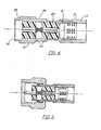
- Figure 5 illustrates a cable plug having mounting arrangements similar to those described with reference to Figures 1, 2 and 3 with the housing of this plug supporting electrically interconnected female and male contacts by means of a dielectric, the female contact being adapted to communicate with the center conductor of a cable on which the cable plug is mounted and with the male contact projecting into the interior of a coupling nut for engagement with a cable jack such as illustrated in Figure 4.
Landscapes
- Coupling Device And Connection With Printed Circuit (AREA)
- Multi-Conductor Connections (AREA)
Abstract
Description
- The present invention relates to solderless connectors suitable for use with semi-rigid coaxial cable.
- Semi-rigid coaxial cable, which is used, particularly, where a high degree of RF shielding is required, comprises a solid tubular outer conductor, usually of copper, centrally disposed within which is an inner conductor spaced from the outer conductor by a dielectric material.
- Direct solder attachment of connectors to semi-rigid cable has, until now, been the only reliable arrangement where a connector is required to function reliably in extreme environmental conditions which may include high vibration levels and high continuous/oscillating mechanical and thermal stress.
- Such direct solder attachment of the connector body to the copper sheath of a semi-rigid coaxial cable has always been a production problem because of the experience and skills that have to be developed to maintain an efficient operation. A narrow time/temperature range is needed to promote solder flow while minimizing undesirable heating effects on the confined cable dielectric. In addition, precision equipment is necessary for repeatable connector positioning. In spite of these difficulties, mechanical cable/connector junctions have not gained wide acceptance. Bulk, cost, lack of permanency, and to some extent, poor performance have been against mechanical connectors. Special cable preparation has led to only limited acceptance of a connector design utilizing a crimp to preknurled cable arrangement (see, for example, U.S. Patent 4,469,390). Nevertheless, a mechanical concept, with designed-in control of the assembly is desirable for consistent performance and for improved productivity.
- Although solderless connectors are well-known and have been widely used in many applications for flexible and semi-rigid cable assemblies, their useful application has been limited to situations in which vibration and stress are not problems.
- A basic requirement in providing a solderless connector for use in such extreme environment conditions is that of providing mechanical and electrical interconnection of high integrity between, the outer conductor and the connector itself. A recent attempt at providing such a connector is embodied in AMP Incorporated's SMA coaxial connector which is described and illustrated on Pages 261 and 262 of AMP Inc.'s catalog entitled "AMP Guide to RF Connectors," Catalog 80-570 published 7/82 (see U.S. Patents 4,408,821 and 4,452,503).
- The AMP connector for semi-rigid coaxial cables utilizes a ferrule or gripper ring which interconnects the main housing of the connector with the outer conductor of the semi-rigid cable. The gripper ring in this design includes a plurality of teeth extending from the annular end of the ring axially of the connector and arranged to be deformed or bent radially inwardly to engage the outward conductor of the cable upon the application of a force to telescope the ferrule and housing together. By this telescoping action the teeth are bent inwardly to engage the outer conductor while the main housing achieves an interference fit with the ferrule thereby to retain the connector on the cable. In this design the mechanical and electrical integrity of the mounting of the connector on the cable involves, firstly, the integrity of the connection between the ferrule and the outer conductor of the cable and, secondly, the interference fit between the ferrule and the housing. Failure of either of these will destroy the integrity of the mounting of the connector on the cable. In particular, it has been found that the interference fit between the ferrule and the housing is subject to failure upon the application of a longitudinally acting force on the connector relative to the cable which is of a magnitude insufficient to damage the cable or the connection of the ferrule with that cable.
- It is an object of the present invention to provide an improved solderiess connector for semi-rigid coaxial cable which provides high mechanical and electrical integrity under extreme environmental conditions in a design which is simple and economical to install (and repair or replace) using simple tools and which is more economical to produce and compact in form.
- According to the present invention there is provided a solderless connector for semi-rigid coaxial cable comprising a connector housing including a portion defining a cable encompassing opening having cable engaging means formed integrally therewith and means to circumferentially compress said portion about a said cable, when in said opening, to bring said engaging means into engagement with said cable and to maintain that engagement.
- The invention will now be described, by way of example, with reference to the accompanying drawings in which:
- Figure 1 is a sectional elevation of a solderless connector in the form of a straight cable plug ready for installation on the prepared end of a semi-rigid coaxial cable, only the portion of the cable on one side of the center line of the connector being shown;
- Figure 2A is an enlarged fragmentary view of the connector illustrated in Figure 1. showing in greater detail the arrangements- for mounting the connector and the cable when in position preparatory to such mounting;
- Figures 2B and 2C are modified forms of the invention.
- Figure 3 is a fragmentary view similar to that of Figure 2 with the connector mounted on the cable;
- Figure 4 is a sectional elevation of a solderless straight cable jack utilizing the mounting arrangements of the connector illustrated in Figures 1, 2 and 3; and
- Figure 5 is a solderless straight cable plug utilizing the mounting arrangement of the connector illustrated in Figures 1, 2 and 3.
- With reference first to Figure 1, an annular monolithic housing 1 defines a
cylindrical bore 2 of a diameter to accommodate in close spaced relationship the outside surface of a semi-rigidcoaxial cable 3. This cable comprises an annular elongate copper, outer conductor 4 concentrically within which extends acopper center conductor 5 with adielectric material 6 disposed therebetween. Acoupling nut 7 is mounted on the housing for rotation relative thereto aboutcentral axis 8. The coupling nut has an inwardly extendingannular flange 9 arranged to cooperate with an outwardly extendingannular flange 10 on the exterior of the housing 1 to permit the mechanical and electrical interconnection of the connector cable assembly with, for example, a corresponding cable jack such as that illustrated in Figure 4, upon the engagement of the female thread 11 of thenut 7 with the corresponding male thread 12 (see Figure 4) of that jack. - A
bushing 13 is pre-loaded onto therear end 14 of the housing 1 prior to the assembly of the connector onto thecable 3. The preloading of thebushing 13 serves to provide for ease of handling and holds thenut 7 captive. - With reference now to both Figures 1 and 2, the housing 1 has a
cylindrical counterbore 15 concentric with theaxis 8 at itsrear end 14 with a plurality ofelongate teeth 16 projecting inwardly from the cylindrical surface of the counterbore toward theaxis 8. The tips of these teeth define an imaginary cylindrical surface of the same diameter, prior to the mounting of the connector of acable 3, as and coaxial with thebore 2. - Four equally spaced apart rows of teeth are provided. These rows each comprise four teeth, equally spaced apart round the circumference of the
counterbore 15, lying in a plane normal to theaxis 8. The teeth are of generally symmetrical triangular cross-section and have a length, around said circumference, approximately equal to the space, around said circumference, between adjacent teeth. - While the exemplary form of connector has been described with a specific arrangement of teeth, it will be appreciated that other arrangements and shapes of teeth, for example, different numbers of rows, different arrangements of teeth from. row to row, elongate teeth some of which extend parallel to the
axis 8, teeth forming individual closed circles (with or without holes, extending radially through saidrear end 14 therein), teeth of asymmetric cross-section to asymmetrically resist longitudinal and/or torsional forces applied to the connector relative to the cable or of conical or frusto-ccnical form may be utilized without departing on the concept of the present invention. - The mounting of the connector onto the
cable 3 is achieved by sliding the connector onto the cable into the position shown in Figure 1 with thebore 2 and the tips of theteeth 16 in close proximity to the outer surface of the outer conductor 4. The housing 1 and bushing 13 are then telescoped together by the application of a telescoping force longitudinally of theaxis 8 as may be applied by a hand operated tool adapted for this purpose. This telescoping action compresses therear end 14 of the housing, circumferentially, and thereby moves theteeth 16 radially inwardly, by virtue of the interaction of substantiallycylindrical bore 17 of bushing 13 with the cylindricalouter surface 18 of therear end 14 of the housing 1, thebore 17 being of a smaller diameter than thesurface 18. The radial thickness and outer diameter of therear end 14 is chosen relative to the material and dimensions of thebushing 13 to provide a desired movement ofteeth 16 radially inwardly towardaxis 8. Interacting frusto-conical surfaces 19 on thebushing 13 and therear end 14 disposed at appropriate angle toaxis 8 to facilitate initial telescoping action to bring thebore 17 into initial contact with thesurface 18. The telescoping action is continued until the housing 1 and bushing 13 occupy the position illustrated in Figure 3 with thebushing 13 abutting the outwardly extendingannular flange 10 of the housing. - The radially inward deformation of the rear end causes the surface of
counterbore 15 to engage and theteeth 16 to engage and deform the surface of the conductor 4 to provide a positive mechanical and electrical interface therewith. The circumferential extension of the teeth provides substantial annular communication between the housing and the outer conductor thereby to strongly resist the longitudinal movement of the housing on the cable upon the application of axial forces on the connector relative to the cable. The circumferentially extending gaps between the teeth serve to resist torsional forces attempting to twist the connector aroundaxis 8 about the cable. - With the connector of the present invention, the integrity of the mechanical and electrical interconnection between the outer conductor of the cable and the connector depends upon only a single interface, namely the interface between the
teeth 16 andrear end 14 with the outer conductor and the cable. The superiority of such an arrangement over the prior art connector described above with its reliance upon two serially disposed interfaces for mechanical and electrical mounting integrity, with the resulting double chance of failure will be readily apparent to one skilled in the art. - Referring now to Figs. 2B and 2C, a modified form of the invention is illustrated wherein the substantially cylindrical
inner surface 17A of the bushing 13A has a slight taper of about 4° so that the ultimate deformed connection between the bushing 13A and thehousing surface 18A is slightly conical with the large dimension of the conical surface being adjacent to thecoupling nut 7. This has the additional advantage of resisting withdrawal force on thecoupling 7 in addition to the resistance to withdrawal force created by the indentation of theteeth 16 into the outer surface 4 of thecoaxial conductor 3. Attention is also drawn to the reducedsection 13B on the end of the bushing which is to engage theouter surface 18A of the cylindrical housing 1. This reduced section is made so that it will expand slightly to provide a frictional jam fit with theouter surface 18A without deforming the housing 1A so that the three pieces (1A, 13A and 7) can be held together as a unitary assembly for slipping onto the end of the solidcoaxial cable 3. - In the operation of the Figure 2B modification of the invention, the bushing 13A is slid forwardly towards
coupling nut 7, this action being solely axial and serving, as it moves over the inner housing 1A, to compress this housing 1A radially around its entire circumference to imbed theteeth 16 into the outer surface of the soft cover jacket 4 of the coaxial - cable. The form of the final bond is illustrated in Fig. 2C and is very similar to that shown in Fig. 3 except that there is a very slight taper of about 4° extending inwardly from thecollar 10 towards the rear of thebushing 13. This has an additional holding function to resist removal forces on the housing 1. - In Fig. 2B, the housing 1A and the bushing 13A are shown in the preassembled condition prior to compression of the housing 1A. As can be seen, the relieved
end 13B of the bushing 13A permits a tight frictional engagement with the housing 1A, being sufficiently deformable by the thinness of the section so that it can form this tight fit with the housing 1A without reducing the diameter of the housing 1A. Therefore the housing 1A can be readily slipped over the end of a coaxial cable. The only function of therelieved end 13B is to permit this slight expansion over the slight taper 18B. Ataper 19A at the end ofportion 13B further facilitates preliminary assembly of the housing 1A, thebushing 13A and thecoupling nut 7 as a unitary piece to be inserted over the end of thecoaxial cable 3. - Fig. 2C also shows another feature of the invention wherein an "0"-ring 13D is carried by the
rear portion 13C of thebushing 13A to provide a weathertight seal with the coax 3. - With reference now to Figure 4, there is illustrated a
straight cable jack 21 having mounting arrangements similar to those described with reference to Figures 1, 2 and 3, for the mounting of the jack onto a semi-rigid coaxial cable. In this arrangement thehousing 22 has arear end 14 similar to that illustrated in Figures 1, 2 and 3 on which is preloaded abushing 13. Inaddition housing 22 supports opposed electricallyinterconnected contacts 23 by means of a dielectric 24, one adjacent therear end 14 for engagement with the center conductor of a cable upon which thejack 21 is mounted. Theforward end 25 has amale thread 25 to facilitate connection with a plug such as described with reference to Figures 1, 2 and 3, by means of engagement of thecoupling nut 7 with theforward end 25; the center conductor of the cable upon which that plug is mounted engaging the otherfemale contact 23 which is located adjacent theforward end 25. - The annular face terminating the
forward end 25 is adapted when the jack is connected to a plug as shown in Figures 1, 2 and 3, to sealingly engage an annular gasket 27 captively mounted in an annular groove formed in an exterior surface of housing 1 adjacent the outwardly extendingflange 10, within thecoupling nut 7. - Figure 5 illustrates a cable plug having mounting arrangements similar to those described with reference to Figures 1, 2 and 3 with the housing of this plug supporting electrically interconnected female and male contacts by means of a dielectric, the female contact being adapted to communicate with the center conductor of a cable on which the cable plug is mounted and with the male contact projecting into the interior of a coupling nut for engagement with a cable jack such as illustrated in Figure 4.
- While the present invention has not been described with reference to the use of any particular materials, suitable materials will be apparent to a man skilled in the art, including constructing the electrically conductive components from any suitable material including stainless steel and that these components may be be gold plated.
Claims (9)
Applications Claiming Priority (2)
| Application Number | Priority Date | Filing Date | Title |
|---|---|---|---|
| US06/715,587 US4668043A (en) | 1985-01-16 | 1985-03-25 | Solderless connectors for semi-rigid coaxial cable |
| US715587 | 1985-03-25 |
Publications (2)
| Publication Number | Publication Date |
|---|---|
| EP0197688A2 true EP0197688A2 (en) | 1986-10-15 |
| EP0197688A3 EP0197688A3 (en) | 1988-08-31 |
Family
ID=24874675
Family Applications (1)
| Application Number | Title | Priority Date | Filing Date |
|---|---|---|---|
| EP86302072A Withdrawn EP0197688A3 (en) | 1985-03-25 | 1986-03-20 | Solderless connector for semi-rigid coaxial cable |
Country Status (4)
| Country | Link |
|---|---|
| US (1) | US4668043A (en) |
| EP (1) | EP0197688A3 (en) |
| JP (1) | JPS61263078A (en) |
| IL (1) | IL78222A0 (en) |
Cited By (5)
| Publication number | Priority date | Publication date | Assignee | Title |
|---|---|---|---|---|
| WO1994001902A1 (en) * | 1992-07-10 | 1994-01-20 | Raychem Corporation | Coaxial cable connection protection system |
| GB2287841A (en) * | 1994-03-22 | 1995-09-27 | Oxley Dev Co Ltd | Connector with a contact gripping arrangement |
| US5486120A (en) * | 1992-07-10 | 1996-01-23 | Raychem Corporation | Coaxial cable connection protection system with multiple chambered, flexible-webbed shroud |
| EP0903809A2 (en) * | 1997-09-18 | 1999-03-24 | Siemens Aktiengesellschaft | Anchoring device and connecting device using it |
| EP1019983A2 (en) * | 1997-08-02 | 2000-07-19 | Noah P. Montena | Connector and method of operation |
Families Citing this family (120)
| Publication number | Priority date | Publication date | Assignee | Title |
|---|---|---|---|---|
| US4834676A (en) * | 1988-03-01 | 1989-05-30 | Solitron Devices Incorporated | Solderless wedge-lock coaxial cable connector |
| US4990106A (en) * | 1989-06-12 | 1991-02-05 | John Mezzalingua Assoc. Inc. | Coaxial cable end connector |
| US5073129A (en) * | 1989-06-12 | 1991-12-17 | John Mezzalingua Assoc. Inc. | Coaxial cable end connector |
| US5002503A (en) * | 1989-09-08 | 1991-03-26 | Viacom International, Inc., Cable Division | Coaxial cable connector |
| US5229011A (en) * | 1990-04-06 | 1993-07-20 | Christy Sr Robert W | Process for pathogen reduction in waste |
| JP2545882Y2 (en) * | 1990-06-26 | 1997-08-27 | 三菱電線工業株式会社 | L type connector for high voltage cable |
| US5041020A (en) * | 1990-07-10 | 1991-08-20 | Amp Incorporated | F series coaxial cable adapter |
| US5269701A (en) * | 1992-03-03 | 1993-12-14 | The Whitaker Corporation | Method for applying a retention sleeve to a coaxial cable connector |
| AU2177192A (en) * | 1992-05-29 | 1993-12-30 | William J. Down | Longitudinally compressible coaxial cable connector |
| US6471545B1 (en) * | 1993-05-14 | 2002-10-29 | The Whitaker Corporation | Coaxial connector for coaxial cable having a corrugated outer conductor |
| US5338225A (en) * | 1993-05-27 | 1994-08-16 | Cabel-Con, Inc. | Hexagonal crimp connector |
| US5651699A (en) * | 1994-03-21 | 1997-07-29 | Holliday; Randall A. | Modular connector assembly for coaxial cables |
| US5501616A (en) * | 1994-03-21 | 1996-03-26 | Holliday; Randall A. | End connector for coaxial cable |
| US5470257A (en) * | 1994-09-12 | 1995-11-28 | John Mezzalingua Assoc. Inc. | Radial compression type coaxial cable end connector |
| USD440539S1 (en) | 1997-08-02 | 2001-04-17 | Noah P. Montena | Closed compression-type coaxial cable connector |
| US6323743B1 (en) * | 1999-08-24 | 2001-11-27 | Tresness Irrevocable Patent Trust | Electronic filter assembly |
| US6210222B1 (en) | 1999-12-13 | 2001-04-03 | Eagle Comtronics, Inc. | Coaxial cable connector |
| USD436076S1 (en) | 2000-04-28 | 2001-01-09 | John Mezzalingua Associates, Inc. | Open compression-type coaxial cable connector |
| USD437826S1 (en) | 2000-04-28 | 2001-02-20 | John Mezzalingua Associates, Inc. | Closed compression-type coaxial cable connector |
| PT1224715E (en) | 2000-05-10 | 2008-08-27 | Thomas & Betts Int | Coaxial connector having detachable locking sleeve |
| USD461778S1 (en) | 2001-09-28 | 2002-08-20 | John Mezzalingua Associates, Inc. | Co-axial cable connector |
| USD462058S1 (en) | 2001-09-28 | 2002-08-27 | John Mezzalingua Associates, Inc. | Co-axial cable connector |
| USD461166S1 (en) | 2001-09-28 | 2002-08-06 | John Mezzalingua Associates, Inc. | Co-axial cable connector |
| USD462327S1 (en) | 2001-09-28 | 2002-09-03 | John Mezzalingua Associates, Inc. | Co-axial cable connector |
| USD468696S1 (en) | 2001-09-28 | 2003-01-14 | John Mezzalingua Associates, Inc. | Co-axial cable connector |
| USD458904S1 (en) | 2001-10-10 | 2002-06-18 | John Mezzalingua Associates, Inc. | Co-axial cable connector |
| USD475975S1 (en) | 2001-10-17 | 2003-06-17 | John Mezzalingua Associates, Inc. | Co-axial cable connector |
| CA2428893C (en) * | 2002-05-31 | 2007-12-18 | Thomas & Betts International, Inc. | Connector for hard-line coaxial cable |
| US6830479B2 (en) * | 2002-11-20 | 2004-12-14 | Randall A. Holliday | Universal crimping connector |
| CN1577978B (en) * | 2003-07-08 | 2010-11-17 | 兰德尔·A·霍利迪 | Universal crimping connector |
| US7014501B2 (en) * | 2003-07-21 | 2006-03-21 | John Mezzalingua Associates, Inc. | Environmentally protected and tamper resistant CATV drop connector and method |
| US6884113B1 (en) * | 2003-10-15 | 2005-04-26 | John Mezzalingua Associates, Inc. | Apparatus for making permanent hardline connection |
| US6808415B1 (en) | 2004-01-26 | 2004-10-26 | John Mezzalingua Associates, Inc. | Clamping and sealing mechanism with multiple rings for cable connector |
| US7329149B2 (en) * | 2004-01-26 | 2008-02-12 | John Mezzalingua Associates, Inc. | Clamping and sealing mechanism with multiple rings for cable connector |
| US7029304B2 (en) * | 2004-02-04 | 2006-04-18 | John Mezzalingua Associates, Inc. | Compression connector with integral coupler |
| US7118416B2 (en) * | 2004-02-18 | 2006-10-10 | John Mezzalingua Associates, Inc. | Cable connector with elastomeric band |
| US7241172B2 (en) * | 2004-04-16 | 2007-07-10 | Thomas & Betts International Inc. | Coaxial cable connector |
| US7063565B2 (en) * | 2004-05-14 | 2006-06-20 | Thomas & Betts International, Inc. | Coaxial cable connector |
| US7048579B2 (en) * | 2004-07-16 | 2006-05-23 | John Mezzalingua Associates, Inc. | Compression connector for coaxial cable |
| US7131868B2 (en) * | 2004-07-16 | 2006-11-07 | John Mezzalingua Associates, Inc. | Compression connector for coaxial cable |
| US7029326B2 (en) * | 2004-07-16 | 2006-04-18 | John Mezzalingua Associates, Inc. | Compression connector for coaxial cable |
| US8075339B2 (en) * | 2004-08-27 | 2011-12-13 | Belden Inc. | Bulge-type coaxial cable connector with plastic sleeve |
| US7410389B2 (en) * | 2004-08-27 | 2008-08-12 | Holliday Randall A | Bulge-type coaxial cable termination assembly |
| US8142223B2 (en) | 2004-08-27 | 2012-03-27 | Belden Inc. | Universal cable connector with interchangeable color bands |
| US9281637B2 (en) | 2004-08-27 | 2016-03-08 | Ppc Broadband, Inc. | Mini coax cable connector |
| US7727015B2 (en) * | 2004-08-27 | 2010-06-01 | Holliday Randall A | Bulge-type coaxial cable connector |
| US20060110977A1 (en) | 2004-11-24 | 2006-05-25 | Roger Matthews | Connector having conductive member and method of use thereof |
| US8157589B2 (en) | 2004-11-24 | 2012-04-17 | John Mezzalingua Associates, Inc. | Connector having a conductively coated member and method of use thereof |
| US7108165B2 (en) * | 2004-12-08 | 2006-09-19 | Apex Mfg. Co., Ltd. | Stapler capable of cutting staple legs one after another |
| US7114990B2 (en) | 2005-01-25 | 2006-10-03 | Corning Gilbert Incorporated | Coaxial cable connector with grounding member |
| US6955563B1 (en) * | 2005-02-08 | 2005-10-18 | Croan Quinn F | RJ type modular connector for coaxial cables |
| IL174146A0 (en) * | 2005-03-11 | 2006-08-01 | Thomas & Betts Int | Coaxial connector with a cable gripping feature |
| CN101253656B (en) * | 2005-06-27 | 2012-01-11 | 普罗布兰德国际有限公司 | End connector for coaxial cable |
| US7455549B2 (en) * | 2005-08-23 | 2008-11-25 | Thomas & Betts International, Inc. | Coaxial cable connector with friction-fit sleeve |
| US7288002B2 (en) | 2005-10-19 | 2007-10-30 | Thomas & Betts International, Inc. | Coaxial cable connector with self-gripping and self-sealing features |
| US7347729B2 (en) * | 2005-10-20 | 2008-03-25 | Thomas & Betts International, Inc. | Prepless coaxial cable connector |
| US20070093128A1 (en) * | 2005-10-20 | 2007-04-26 | Thomas & Betts International, Inc. | Coaxial cable connector having collar with cable gripping features |
| US7588460B2 (en) * | 2007-04-17 | 2009-09-15 | Thomas & Betts International, Inc. | Coaxial cable connector with gripping ferrule |
| US7794275B2 (en) * | 2007-05-01 | 2010-09-14 | Thomas & Betts International, Inc. | Coaxial cable connector with inner sleeve ring |
| US7566236B2 (en) | 2007-06-14 | 2009-07-28 | Thomas & Betts International, Inc. | Constant force coaxial cable connector |
| US8113875B2 (en) | 2008-09-30 | 2012-02-14 | Belden Inc. | Cable connector |
| US8025518B2 (en) | 2009-02-24 | 2011-09-27 | Corning Gilbert Inc. | Coaxial connector with dual-grip nut |
| US8029315B2 (en) | 2009-04-01 | 2011-10-04 | John Mezzalingua Associates, Inc. | Coaxial cable connector with improved physical and RF sealing |
| US7824216B2 (en) | 2009-04-02 | 2010-11-02 | John Mezzalingua Associates, Inc. | Coaxial cable continuity connector |
| US7892005B2 (en) | 2009-05-19 | 2011-02-22 | John Mezzalingua Associates, Inc. | Click-tight coaxial cable continuity connector |
| US9017101B2 (en) | 2011-03-30 | 2015-04-28 | Ppc Broadband, Inc. | Continuity maintaining biasing member |
| US9570845B2 (en) | 2009-05-22 | 2017-02-14 | Ppc Broadband, Inc. | Connector having a continuity member operable in a radial direction |
| US8444445B2 (en) | 2009-05-22 | 2013-05-21 | Ppc Broadband, Inc. | Coaxial cable connector having electrical continuity member |
| US8287320B2 (en) | 2009-05-22 | 2012-10-16 | John Mezzalingua Associates, Inc. | Coaxial cable connector having electrical continuity member |
| US8573996B2 (en) | 2009-05-22 | 2013-11-05 | Ppc Broadband, Inc. | Coaxial cable connector having electrical continuity member |
| US8272893B2 (en) | 2009-11-16 | 2012-09-25 | Corning Gilbert Inc. | Integrally conductive and shielded coaxial cable connector |
| JP2011198566A (en) * | 2010-03-18 | 2011-10-06 | Sumitomo Wiring Syst Ltd | Charging connector |
| US8177582B2 (en) | 2010-04-02 | 2012-05-15 | John Mezzalingua Associates, Inc. | Impedance management in coaxial cable terminations |
| US7934954B1 (en) | 2010-04-02 | 2011-05-03 | John Mezzalingua Associates, Inc. | Coaxial cable compression connectors |
| US8468688B2 (en) | 2010-04-02 | 2013-06-25 | John Mezzalingua Associates, LLC | Coaxial cable preparation tools |
| US9166306B2 (en) | 2010-04-02 | 2015-10-20 | John Mezzalingua Associates, LLC | Method of terminating a coaxial cable |
| TWI549386B (en) | 2010-04-13 | 2016-09-11 | 康寧吉伯特公司 | Coaxial connector with inhibited ingress and improved grounding |
| US8152551B2 (en) | 2010-07-22 | 2012-04-10 | John Mezzalingua Associates, Inc. | Port seizing cable connector nut and assembly |
| US8079860B1 (en) | 2010-07-22 | 2011-12-20 | John Mezzalingua Associates, Inc. | Cable connector having threaded locking collet and nut |
| US8113879B1 (en) | 2010-07-27 | 2012-02-14 | John Mezzalingua Associates, Inc. | One-piece compression connector body for coaxial cable connector |
| US8888526B2 (en) | 2010-08-10 | 2014-11-18 | Corning Gilbert, Inc. | Coaxial cable connector with radio frequency interference and grounding shield |
| US8556656B2 (en) | 2010-10-01 | 2013-10-15 | Belden, Inc. | Cable connector with sliding ring compression |
| US8167636B1 (en) | 2010-10-15 | 2012-05-01 | John Mezzalingua Associates, Inc. | Connector having a continuity member |
| US8075338B1 (en) | 2010-10-18 | 2011-12-13 | John Mezzalingua Associates, Inc. | Connector having a constant contact post |
| US8167646B1 (en) | 2010-10-18 | 2012-05-01 | John Mezzalingua Associates, Inc. | Connector having electrical continuity about an inner dielectric and method of use thereof |
| US8323053B2 (en) | 2010-10-18 | 2012-12-04 | John Mezzalingua Associates, Inc. | Connector having a constant contact nut |
| US8167635B1 (en) | 2010-10-18 | 2012-05-01 | John Mezzalingua Associates, Inc. | Dielectric sealing member and method of use thereof |
| TWI558022B (en) | 2010-10-27 | 2016-11-11 | 康寧吉伯特公司 | Push-on cable connector with a coupler and retention and release mechanism |
| US8337229B2 (en) | 2010-11-11 | 2012-12-25 | John Mezzalingua Associates, Inc. | Connector having a nut-body continuity element and method of use thereof |
| US8414322B2 (en) | 2010-12-14 | 2013-04-09 | Ppc Broadband, Inc. | Push-on CATV port terminator |
| US8398421B2 (en) | 2011-02-01 | 2013-03-19 | John Mezzalingua Associates, Inc. | Connector having a dielectric seal and method of use thereof |
| US8157588B1 (en) | 2011-02-08 | 2012-04-17 | Belden Inc. | Cable connector with biasing element |
| US8465322B2 (en) | 2011-03-25 | 2013-06-18 | Ppc Broadband, Inc. | Coaxial cable connector |
| US8342879B2 (en) | 2011-03-25 | 2013-01-01 | John Mezzalingua Associates, Inc. | Coaxial cable connector |
| US8366481B2 (en) | 2011-03-30 | 2013-02-05 | John Mezzalingua Associates, Inc. | Continuity maintaining biasing member |
| US8388377B2 (en) | 2011-04-01 | 2013-03-05 | John Mezzalingua Associates, Inc. | Slide actuated coaxial cable connector |
| US8348697B2 (en) | 2011-04-22 | 2013-01-08 | John Mezzalingua Associates, Inc. | Coaxial cable connector having slotted post member |
| WO2012162431A2 (en) | 2011-05-26 | 2012-11-29 | Belden Inc. | Coaxial cable connector with conductive seal |
| US9711917B2 (en) | 2011-05-26 | 2017-07-18 | Ppc Broadband, Inc. | Band spring continuity member for coaxial cable connector |
| US8758050B2 (en) | 2011-06-10 | 2014-06-24 | Hiscock & Barclay LLP | Connector having a coupling member for locking onto a port and maintaining electrical continuity |
| US8591244B2 (en) | 2011-07-08 | 2013-11-26 | Ppc Broadband, Inc. | Cable connector |
| US9190744B2 (en) | 2011-09-14 | 2015-11-17 | Corning Optical Communications Rf Llc | Coaxial cable connector with radio frequency interference and grounding shield |
| US20130072057A1 (en) | 2011-09-15 | 2013-03-21 | Donald Andrew Burris | Coaxial cable connector with integral radio frequency interference and grounding shield |
| US9147955B2 (en) | 2011-11-02 | 2015-09-29 | Ppc Broadband, Inc. | Continuity providing port |
| US9136654B2 (en) | 2012-01-05 | 2015-09-15 | Corning Gilbert, Inc. | Quick mount connector for a coaxial cable |
| US9407016B2 (en) | 2012-02-22 | 2016-08-02 | Corning Optical Communications Rf Llc | Coaxial cable connector with integral continuity contacting portion |
| US9287659B2 (en) | 2012-10-16 | 2016-03-15 | Corning Optical Communications Rf Llc | Coaxial cable connector with integral RFI protection |
| US9147963B2 (en) | 2012-11-29 | 2015-09-29 | Corning Gilbert Inc. | Hardline coaxial connector with a locking ferrule |
| US9153911B2 (en) | 2013-02-19 | 2015-10-06 | Corning Gilbert Inc. | Coaxial cable continuity connector |
| US9172154B2 (en) | 2013-03-15 | 2015-10-27 | Corning Gilbert Inc. | Coaxial cable connector with integral RFI protection |
| WO2014172554A1 (en) | 2013-04-17 | 2014-10-23 | Ppc Broadband, Inc. | Post assembly for coaxial cable connectors |
| US10290958B2 (en) | 2013-04-29 | 2019-05-14 | Corning Optical Communications Rf Llc | Coaxial cable connector with integral RFI protection and biasing ring |
| EP3000154B1 (en) | 2013-05-20 | 2019-05-01 | Corning Optical Communications RF LLC | Coaxial cable connector with integral rfi protection |
| US9548557B2 (en) | 2013-06-26 | 2017-01-17 | Corning Optical Communications LLC | Connector assemblies and methods of manufacture |
| US9048599B2 (en) | 2013-10-28 | 2015-06-02 | Corning Gilbert Inc. | Coaxial cable connector having a gripping member with a notch and disposed inside a shell |
| WO2016073309A1 (en) | 2014-11-03 | 2016-05-12 | Corning Optical Communications Rf Llc | Coaxial cable connector with integral rfi protection |
| US10033122B2 (en) | 2015-02-20 | 2018-07-24 | Corning Optical Communications Rf Llc | Cable or conduit connector with jacket retention feature |
| US9590287B2 (en) | 2015-02-20 | 2017-03-07 | Corning Optical Communications Rf Llc | Surge protected coaxial termination |
| US10211547B2 (en) | 2015-09-03 | 2019-02-19 | Corning Optical Communications Rf Llc | Coaxial cable connector |
| US9525220B1 (en) | 2015-11-25 | 2016-12-20 | Corning Optical Communications LLC | Coaxial cable connector |
Citations (5)
| Publication number | Priority date | Publication date | Assignee | Title |
|---|---|---|---|---|
| GB930096A (en) * | 1960-12-01 | 1963-07-03 | Kay & Co Eng Ltd | Improvements in couplings and junctions for co-axial and like electric cables |
| US3537065A (en) * | 1967-01-12 | 1970-10-27 | Jerrold Electronics Corp | Multiferrule cable connector |
| FR2219553A1 (en) * | 1973-02-26 | 1974-09-20 | Cables De Lyon Geoffroy Delore | |
| US4408821A (en) * | 1979-07-09 | 1983-10-11 | Amp Incorporated | Connector for semi-rigid coaxial cable |
| EP0116760A1 (en) * | 1983-01-21 | 1984-08-29 | Omni Spectra, Inc. | Solderless connectors for semi-rigid coaxial cable |
Family Cites Families (7)
| Publication number | Priority date | Publication date | Assignee | Title |
|---|---|---|---|---|
| US3668612A (en) * | 1970-08-07 | 1972-06-06 | Lindsay Specialty Prod Ltd | Cable connector |
| US3757279A (en) * | 1972-05-15 | 1973-09-04 | Jerrold Electronics Corp | Tor diameters electrical connector operable for diverse coaxial cable center conduc |
| US3846738A (en) * | 1973-04-05 | 1974-11-05 | Lindsay Specialty Prod Ltd | Cable connector |
| US4452503A (en) * | 1981-01-02 | 1984-06-05 | Amp Incorporated | Connector for semirigid coaxial cable |
| US4400050A (en) * | 1981-05-18 | 1983-08-23 | Gilbert Engineering Co., Inc. | Fitting for coaxial cable |
| US4469390A (en) * | 1982-06-09 | 1984-09-04 | Kings Electronics Co., Inc. | Crimped connector |
| US4509816A (en) * | 1983-08-31 | 1985-04-09 | Wolfgang Freitag | Plug connector for co-axial electrical cables |
-
1985
- 1985-03-25 US US06/715,587 patent/US4668043A/en not_active Expired - Fee Related
-
1986
- 1986-03-20 EP EP86302072A patent/EP0197688A3/en not_active Withdrawn
- 1986-03-21 IL IL78222A patent/IL78222A0/en unknown
- 1986-03-25 JP JP61065027A patent/JPS61263078A/en active Pending
Patent Citations (5)
| Publication number | Priority date | Publication date | Assignee | Title |
|---|---|---|---|---|
| GB930096A (en) * | 1960-12-01 | 1963-07-03 | Kay & Co Eng Ltd | Improvements in couplings and junctions for co-axial and like electric cables |
| US3537065A (en) * | 1967-01-12 | 1970-10-27 | Jerrold Electronics Corp | Multiferrule cable connector |
| FR2219553A1 (en) * | 1973-02-26 | 1974-09-20 | Cables De Lyon Geoffroy Delore | |
| US4408821A (en) * | 1979-07-09 | 1983-10-11 | Amp Incorporated | Connector for semi-rigid coaxial cable |
| EP0116760A1 (en) * | 1983-01-21 | 1984-08-29 | Omni Spectra, Inc. | Solderless connectors for semi-rigid coaxial cable |
Cited By (9)
| Publication number | Priority date | Publication date | Assignee | Title |
|---|---|---|---|---|
| WO1994001902A1 (en) * | 1992-07-10 | 1994-01-20 | Raychem Corporation | Coaxial cable connection protection system |
| US5469613A (en) * | 1992-07-10 | 1995-11-28 | Raychem Corporation | Tool for connecting a coaxial cable terminus to a connection jack |
| US5486120A (en) * | 1992-07-10 | 1996-01-23 | Raychem Corporation | Coaxial cable connection protection system with multiple chambered, flexible-webbed shroud |
| GB2287841A (en) * | 1994-03-22 | 1995-09-27 | Oxley Dev Co Ltd | Connector with a contact gripping arrangement |
| GB2287841B (en) * | 1994-03-22 | 1998-03-25 | Oxley Dev Co Ltd | Connector |
| EP1019983A2 (en) * | 1997-08-02 | 2000-07-19 | Noah P. Montena | Connector and method of operation |
| EP1019983A4 (en) * | 1997-08-02 | 2000-11-02 | Noah P Montena | Connector and method of operation |
| EP0903809A2 (en) * | 1997-09-18 | 1999-03-24 | Siemens Aktiengesellschaft | Anchoring device and connecting device using it |
| EP0903809A3 (en) * | 1997-09-18 | 2001-04-18 | Siemens Aktiengesellschaft | Anchoring device and connecting device using it |
Also Published As
| Publication number | Publication date |
|---|---|
| US4668043A (en) | 1987-05-26 |
| IL78222A0 (en) | 1986-07-31 |
| EP0197688A3 (en) | 1988-08-31 |
| JPS61263078A (en) | 1986-11-21 |
Similar Documents
| Publication | Publication Date | Title |
|---|---|---|
| US4668043A (en) | Solderless connectors for semi-rigid coaxial cable | |
| US4596434A (en) | Solderless connectors for semi-rigid coaxial cable | |
| US6183298B1 (en) | Connector for coaxial cable with friction locking arrangement | |
| US7794275B2 (en) | Coaxial cable connector with inner sleeve ring | |
| US4022966A (en) | Ground connector | |
| EP1779470B1 (en) | Compression connector for coaxial cable | |
| EP2422410B1 (en) | Coaxial connector for corrugated cable with corrugated sealing | |
| US5059139A (en) | Coaxial cable fitting | |
| US4173385A (en) | Watertight cable connector | |
| KR900000289B1 (en) | Direct crimp coaxial cable connector | |
| EP2304847B1 (en) | Snap-on coaxial cable connector | |
| EP0001701B1 (en) | Electrical connector for terminating coaxial cable | |
| US10833432B2 (en) | Easily assembled coaxial cable and connector with rear body | |
| EP0326447B1 (en) | Socket contact for an electrical connector | |
| US5181861A (en) | Manually installable coaxial cable connector | |
| EP3555968B1 (en) | Multiple piece contact for an electrical connector | |
| EP0599602A1 (en) | Coaxial connector for corrugated conduit | |
| EP2063501B1 (en) | Coaxial Cable Connector for Corrugated Cable | |
| EP0161910A2 (en) | Multi-conductor cable connector | |
| CN105340134A (en) | Quick mount connector for a coaxial cable | |
| MX2008004953A (en) | Adjustable connector for electrical cable. | |
| US5358433A (en) | Female electrical contact terminal for a connector | |
| US3331917A (en) | Coaxial and shielded in-line termination | |
| US3474391A (en) | Coaxial connector | |
| CA1216910A (en) | Solderless connectors for semi-rigid coaxial cable |
Legal Events
| Date | Code | Title | Description |
|---|---|---|---|
| PUAI | Public reference made under article 153(3) epc to a published international application that has entered the european phase |
Free format text: ORIGINAL CODE: 0009012 |
|
| AK | Designated contracting states |
Kind code of ref document: A2 Designated state(s): AT BE CH DE FR GB IT LI LU NL SE |
|
| PUAL | Search report despatched |
Free format text: ORIGINAL CODE: 0009013 |
|
| AK | Designated contracting states |
Kind code of ref document: A3 Designated state(s): AT BE CH DE FR GB IT LI LU NL SE |
|
| STAA | Information on the status of an ep patent application or granted ep patent |
Free format text: STATUS: THE APPLICATION IS DEEMED TO BE WITHDRAWN |
|
| 18D | Application deemed to be withdrawn |
Effective date: 19880405 |
|
| RIN1 | Information on inventor provided before grant (corrected) |
Inventor name: SABA, ROBERT ABRAHAM Inventor name: HARHEN, PAUL FRANCIS Inventor name: DUCHARME, ROGER ROLAND |