EP0197483A2 - Safety reservoir snap on overcap for parenteral drug container - Google Patents
Safety reservoir snap on overcap for parenteral drug container Download PDFInfo
- Publication number
- EP0197483A2 EP0197483A2 EP86104379A EP86104379A EP0197483A2 EP 0197483 A2 EP0197483 A2 EP 0197483A2 EP 86104379 A EP86104379 A EP 86104379A EP 86104379 A EP86104379 A EP 86104379A EP 0197483 A2 EP0197483 A2 EP 0197483A2
- Authority
- EP
- European Patent Office
- Prior art keywords
- container
- cap
- drug
- closure
- top portion
- Prior art date
- Legal status (The legal status is an assumption and is not a legal conclusion. Google has not performed a legal analysis and makes no representation as to the accuracy of the status listed.)
- Granted
Links
- 239000003814 drug Substances 0.000 title claims abstract description 48
- 229940079593 drug Drugs 0.000 title claims abstract description 48
- 239000011324 bead Substances 0.000 claims abstract description 8
- 238000003780 insertion Methods 0.000 claims abstract description 5
- 230000037431 insertion Effects 0.000 claims abstract description 5
- 239000003085 diluting agent Substances 0.000 claims description 16
- 244000043261 Hevea brasiliensis Species 0.000 claims description 9
- 238000002347 injection Methods 0.000 claims description 9
- 239000007924 injection Substances 0.000 claims description 9
- 229920003052 natural elastomer Polymers 0.000 claims description 9
- 229920001194 natural rubber Polymers 0.000 claims description 9
- 239000000463 material Substances 0.000 claims description 7
- 238000010276 construction Methods 0.000 abstract description 7
- 230000000118 anti-neoplastic effect Effects 0.000 abstract description 3
- XAGFODPZIPBFFR-UHFFFAOYSA-N aluminium Chemical compound [Al] XAGFODPZIPBFFR-UHFFFAOYSA-N 0.000 description 8
- 229910052782 aluminium Inorganic materials 0.000 description 8
- 239000002246 antineoplastic agent Substances 0.000 description 6
- 229940041181 antineoplastic drug Drugs 0.000 description 6
- XLYOFNOQVPJJNP-UHFFFAOYSA-N water Chemical compound O XLYOFNOQVPJJNP-UHFFFAOYSA-N 0.000 description 5
- 239000004033 plastic Substances 0.000 description 4
- 229920003051 synthetic elastomer Polymers 0.000 description 4
- 239000007788 liquid Substances 0.000 description 3
- 239000000203 mixture Substances 0.000 description 3
- 239000007787 solid Substances 0.000 description 3
- 238000012360 testing method Methods 0.000 description 3
- 230000000694 effects Effects 0.000 description 2
- 229920001971 elastomer Polymers 0.000 description 2
- 231100001261 hazardous Toxicity 0.000 description 2
- 238000000034 method Methods 0.000 description 2
- 238000000465 moulding Methods 0.000 description 2
- 239000007921 spray Substances 0.000 description 2
- 206010067484 Adverse reaction Diseases 0.000 description 1
- WQZGKKKJIJFFOK-GASJEMHNSA-N Glucose Chemical compound OC[C@H]1OC(O)[C@H](O)[C@@H](O)[C@@H]1O WQZGKKKJIJFFOK-GASJEMHNSA-N 0.000 description 1
- 206010028980 Neoplasm Diseases 0.000 description 1
- 239000005062 Polybutadiene Substances 0.000 description 1
- 206010040880 Skin irritation Diseases 0.000 description 1
- FAPWRFPIFSIZLT-UHFFFAOYSA-M Sodium chloride Chemical compound [Na+].[Cl-] FAPWRFPIFSIZLT-UHFFFAOYSA-M 0.000 description 1
- 230000006838 adverse reaction Effects 0.000 description 1
- 239000000443 aerosol Substances 0.000 description 1
- 230000000711 cancerogenic effect Effects 0.000 description 1
- 231100000315 carcinogenic Toxicity 0.000 description 1
- 150000001993 dienes Chemical class 0.000 description 1
- 239000000806 elastomer Substances 0.000 description 1
- 239000005308 flint glass Substances 0.000 description 1
- 238000007689 inspection Methods 0.000 description 1
- 230000003211 malignant effect Effects 0.000 description 1
- 238000012986 modification Methods 0.000 description 1
- 230000004048 modification Effects 0.000 description 1
- 239000000178 monomer Substances 0.000 description 1
- 229920002857 polybutadiene Polymers 0.000 description 1
- 230000002265 prevention Effects 0.000 description 1
- 230000001681 protective effect Effects 0.000 description 1
- 239000005060 rubber Substances 0.000 description 1
- 231100000075 skin burn Toxicity 0.000 description 1
- 230000036556 skin irritation Effects 0.000 description 1
- 231100000475 skin irritation Toxicity 0.000 description 1
- 239000000243 solution Substances 0.000 description 1
- 239000008223 sterile water Substances 0.000 description 1
- 229920001897 terpolymer Polymers 0.000 description 1
- 231100000331 toxic Toxicity 0.000 description 1
- 230000002588 toxic effect Effects 0.000 description 1
- 238000013022 venting Methods 0.000 description 1
Images
Classifications
-
- B—PERFORMING OPERATIONS; TRANSPORTING
- B65—CONVEYING; PACKING; STORING; HANDLING THIN OR FILAMENTARY MATERIAL
- B65D—CONTAINERS FOR STORAGE OR TRANSPORT OF ARTICLES OR MATERIALS, e.g. BAGS, BARRELS, BOTTLES, BOXES, CANS, CARTONS, CRATES, DRUMS, JARS, TANKS, HOPPERS, FORWARDING CONTAINERS; ACCESSORIES, CLOSURES, OR FITTINGS THEREFOR; PACKAGING ELEMENTS; PACKAGES
- B65D51/00—Closures not otherwise provided for
- B65D51/002—Closures to be pierced by an extracting-device for the contents and fixed on the container by separate retaining means
Definitions
- This invention relates to a device for prevention of aerosoling of parenteral antineoplastic or other potentially hazardous drugs into the environment during reconsitution of the drug in the drug container and withdrawal of it from the container for use.
- Antineoplastic drugs i.e. drugs used to prevent growth and spread of tumors and malignant cells, present special safety problems to medical personnel, e.g. hospital and pharmacy personnel. This is because most of the drugs are toxic and because they are potentially carcinogenic to healthy humans and may also cause other adverse reactions, e.g. skin irritation or burns. Thus, exposure to the drugs by pharmacists, nurses, physicians and other personnel involved in handling these drugs must be minimized.
- Reconstitution is normally carried out as follows:
- the drug container i.e. bottle or vial
- drug e.g. lyophilized material.
- a hypodermic needle associated with a diluent containing hypodermic syringe is pushed through the drug container closure to enter the interior of the container, and the syringe is used'to inject diluent into the container.
- the syringe is then removed.
- the material in the container is then swirled to provide uniformity.
- a hypodermic syringe is then reinserted into the container, and the diluted drug is pulled into the syringe, and the needle is withdrawn.
- the injecting of the diluent causes a pressure buildup in the container.
- drug may escape from the container, e.g. being forced out by the pressure during the injection of diluent or when the needle is withdrawn, and become aercscled into the environment.
- reconstitution t5 normally carried out utilizing elaborate protective equipment, e.g. hoods and special gowns, face masks and gloves. Special venting devices are also sometimes used to reduce internal pressure.
- elaborate protective equipment e.g. hoods and special gowns, face masks and gloves.
- Special venting devices are also sometimes used to reduce internal pressure.
- the hazards of antineoplastic drugs and the elaborate precautions for their reconstitution are described in NIH Publication No. 83-2621 which is titled "Recommendations for the Safe Handling of Antineoplastic Drugs".
- hoods recommended for protection in the NIH publication are Class II laminar flow biological safety cabinets which are relatively expensive. In the some 8,000 treatment centers without this equipment, there is a high risk not only to the personnel directly involved but there is danger of escaping drug being aerosoled into the air circulation system of the entire facility.
- the embodiment which has been commercially available is made of relatively rigid plastic and is over two inches deep and contains an inwardly extending guide passageway for the hypodermic needle, a relatively deep aerosol trapping chamber and structure for locking the device on a drug container consisting of a plurality of inwardly and upwardly projecting tabs.
- the structure is complicated and of multipiece construction requiring aissembly and its depth dimension increases the risk of ovarturning the container.
- the invention herein is directed to a very simple cap for application over the closure and finish of a parenteral antineoplastic or other potentially hazardous drug container to prevent outflow of drug to the environment on reconstitution of the drug by injection into the drug container cf dileunt with a hypodermic syringe and needle and withdrawal of reconstituted drug into the syringe and withdrawal of the needle from the container.
- the overcap includes a cylindrical drug trapping chamber, e.g. airlock or safety reservoir, with a depth to diameter ratio up to 4:1 or more but preferably less than 1:1, elasticity and inner surface construction to provide pressure against the container closure to seal against leakage, a beveled continuous annular locking flange, and an upstanding annular bead defining a target area for hypodermic needle insertion.
- the overcap in its preferred embodiment does not substantially increase the height of the drug container and thus does not provide an unwieldly structure with increased potential for overturning.
- the overcap is readily constructed of natural rubber and/or synthetic elastomer and is readily formed to be of one piece construction in a conventional molding process.
- the overcap comprises
- a drug vial 10 having a closure consisting of a rubber stopper 12 which is held to the vial finish by an aluminum cap 14 having its plastic flip off portion removed to expose the stopper for piercing by needle 16.
- the aluminum cap 14 presents a substantially cylindrical surface for receiving the overcap of the invention.
- the overcap 17 of the invention includes a substantially cylindrical top portion 20 having a vertical axis which as is shown in Fig. 3 is aligned with the vertical axis of the vial when the overcap has been applied.
- annular cross section skirt 22 Integral with the top portion 20 and depending downwardly therefrom is an annular cross section skirt 22 having an inner surface substantially conforming to the contour of the outer surface of the closure and adapted to receive and press against said outer surface.
- the inner diameter of the skirt is equal to or slightly less than the outer diameter of aluminum cap 14.
- a cylindrical chamber 24 is inset into the lower surface of top portion 20 and has a vertical axis aligned with the vertical axis of top portion 20. It has a depth to diameter ratio preferably ranging from about 0.25:1 to about 0.5:1 and typically has a diameter ranging from about 0.25 inches to about 0.5 inches. The depth to diameter ratio is very important because it allows the top of the overcap to be in proximity with the top of the drug container closure, e.g. 0.15 to 0.4 inches therefrom (not including the vertical dimension of bead 36 discussed later) whereby there is substantially no increased risk of overturning due to the overcap.
- An annular shoulder 26 is defined in top portion 20 by the sidewall of cylindrical chamber 24 and has a lower surface 28 ( F ig. 2) defined by the lower surface of top portion 20.
- Shoulder 26 has an inner diameter which is the same as the diameter of chamber 24 and an outer diameter which is the same as the inner diameter of skirt 22 and the ratio of its outer diameter to its inner diameter preferably ranges from about 1.75:1 to about 2.25:1.
- An annular locking flange 30 is integral with the bottom of skirt 22 and has an inwardly angled surface 32 providing circular access at the bottom of the overcap with a diameter greater than the outer diameter of aluminum cap 14 and is angled upwardly, e.g. at 40 to 50 degrees, preferably at 45 degrees with the lower surface of the overcap and terminates in a vertical upper inner portion having an inside diameter corresponding approximately to the outside diameter of the neck of vial 10. It has an upper surface 34 which provides a locking lip to engage against aluminum cap 14 at the bottom of the container finish.
- the dimension of the surface 28 in the radial direction and the depth dimension of skirt 22, i.e. the vertical distance between the outer margin of suface 28 and lip 34 as denoted by reference numberal 23, are selected to provide sufficient contact surface and the inner diameter and depth of skirt 22 are selected to provide a pinching effect, i.e. a pressing effect against cap 14, to prevent leakage between the overcap 17 and the cap 14.
- An upstanding annular bead 36 is part of and in the upper surface of top portion 20 and is axially aligned with the vertical axis of top portion 20.
- the bead is preferably semicircular in vertical cross section and preferably has a small radial dimension, e.g. 1/64 to 1/16 inch, very preferably 1/32 inch so as not to add materially to the vertical dimension of the overcap.
- the bead 36 encircles and thereby defines a circular target area 38 for insertion through the overcap / of a hypodermic needle.
- the target area 38 is centered over the cylindrical chamber 24.and on application of the overcap is centered over the target (puncture) area 40 of stopper 12.
- the vertical dimension of the material of the top portion 20 under target area 38 is sufficiently small, e.g. 0.05-0.2 inches, and the material of construction of the overcap is such that the top portion 10 at target area 38 is readily punctured with a hypodermic recile.
- the overcap 17 is preferably constructed of natural rubber as natural rubbber has an elasticity such that with the aforedescribed dimensions, the overcap 17 is readily forced over stopper 12 and aluminum cap 14 by aligning the angled surface 32 over the stopper 12 and cap 14 and pushing downwardly, and such that with the aforedescribed dimen- sicns, the surface 28 and inner surface of skirt 22 (along dimension 23) on application of overcap 17 press against cap 14 and stopper 12 and the finish of vial 10 to prevent leakage between the overcap 17 and cap 14.
- the overcap 17 car- also very appropriately be constructed of synthetic elastomers or a blend of natural rubber with synthetic elastomers but the elasticity should preferably be the same as or close to that of natural rubber.
- useful synthetic elastomers include those normally blended with natural rubber, e.g. polybutadiene, polystyrene-butadiene, necprene and terpolymer elastomer made from ethylene- prcpylene diene monomer (EPDM).
- natural rubber e.g. polybutadiene, polystyrene-butadiene, necprene and terpolymer elastomer made from ethylene- prcpylene diene monomer (EPDM).
- EPDM ethylene- prcpylene diene monomer
- the overcap herein is readily made of one piece construction in a molding process.
- the overcap herein is utilized as follows: The overcap 17 is positioned above the aluminum cap 14 which is in position over stopper 12 and the finish of a vial 10 (e.g. a 30cc. vial) which contains antineoplastic drug ready for reconstitution (the plastic flip top portion of cap 14 has already been removed to expose stopper 12 so that cap 14 and stopper 12 are as depicted in Fig. 3) and the angled surface 32 is positioned so as to overlie the portion of cap 14 at the edge of the stopper. Then overcap 17 is pushed downwardly so as to fit over the cap 14 and so that locking lip 34 engages cap 14 at a position under the container finish as depicted in Fig. 3. Then a hypodermic needle 16, e.g.
- the vial 10 is then moved to swirl the liquid injected therein to dissolve the drug.
- the needle 16 is then reinserted and the syringe is then used to withdraw the reconstituted drug. Then the needle 16 is withdrawn first from stopper 12 and then from overcap 17.
- the stopper 12 and overcap 17 exert a wiping action to wipe residual drug therefrom so that it returns to vial 10 or to chamber 24.
- drug is forced out of vial 10 by the increased pressure due to initial injection of diluent, either during said injection c.r during dissolving/swirling or during withdrawal of reconstituted drug into the syringe or withdrawal of the needLe 16 from the stopper 12 and overcap 17, it is trapped in chamber 24.
- the 18 gauge needle 16 is used to prenetrate the overcap 17 but not the stopper 12. Diluent is injected into the chamber in 0.25 cc. increments with inspection of the overcap equipped vial between injections for leakage at the puncture area and at the seal area between overcap 17 and cap 14. No leakage is observed until the fifth successive injection when leakage is noted in the seal area.
- the 18 gauge needle is used to puncture the overcap at the target area 38 wherein the thickness is about 0.1 inch. The needle is then withdrawn. The needle is then inserted again at a second puncture point in target area 38 and water is injected into chamber 24. No leakage is noted out of the first puncture passageway even though up to 1.0 ml. is injected into chamber 24 due to the elasticity and resiliency of the natural rubber material of overcap 17.
Abstract
Description
- This invention relates to a device for prevention of aerosoling of parenteral antineoplastic or other potentially hazardous drugs into the environment during reconsitution of the drug in the drug container and withdrawal of it from the container for use.
- Antineoplastic drugs, i.e. drugs used to prevent growth and spread of tumors and malignant cells, present special safety problems to medical personnel, e.g. hospital and pharmacy personnel. This is because most of the drugs are toxic and because they are potentially carcinogenic to healthy humans and may also cause other adverse reactions, e.g. skin irritation or burns. Thus, exposure to the drugs by pharmacists, nurses, physicians and other personnel involved in handling these drugs must be minimized.
- There would normally be opportunity for medical personnel to be exposed to these drugs because of their nature. These drugs are not sold as compositions ready for administration. This is because when they are combined with diluent, the compositions which are formed normally have a shelf life ranging from several hours to a few days. Thus, in the ordinary course, diluent (usually sterile water, saline solution, dextrose solution or dextrose-saline solution, is added just prior to administration. Most of the drugs are sold in solid form although some are available in solid or liquid form. The diluent is added to the solid drugs to dissolve them and provide selected concentration. The diluent is admixed with drug in liquid form to dilute it to selected concentration. This admixing of diluent with antineoplastic drug is referred to herein as reconstitution. The term "reconstitution" has come into use in this milieu because the drug to which diluent is added has often been lyophilized.
- Reconstitution is normally carried out as follows: The drug container (i.e. bottle or vial) is obtained about one-third to one-half filled with drug, e.g. lyophilized material. A hypodermic needle associated with a diluent containing hypodermic syringe is pushed through the drug container closure to enter the interior of the container, and the syringe is used'to inject diluent into the container. The syringe is then removed. The material in the container is then swirled to provide uniformity. A hypodermic syringe is then reinserted into the container, and the diluted drug is pulled into the syringe, and the needle is withdrawn. The injecting of the diluent causes a pressure buildup in the container. As a result of the pressure buildup, drug may escape from the container, e.g. being forced out by the pressure during the injection of diluent or when the needle is withdrawn, and become aercscled into the environment. As a result, reconstitution t5 normally carried out utilizing elaborate protective equipment, e.g. hoods and special gowns, face masks and gloves. Special venting devices are also sometimes used to reduce internal pressure. The hazards of antineoplastic drugs and the elaborate precautions for their reconstitution are described in NIH Publication No. 83-2621 which is titled "Recommendations for the Safe Handling of Antineoplastic Drugs".
- The hoods recommended for protection in the NIH publication are Class II laminar flow biological safety cabinets which are relatively expensive. In the some 8,000 treatment centers without this equipment, there is a high risk not only to the personnel directly involved but there is danger of escaping drug being aerosoled into the air circulation system of the entire facility.
- Consideration has been given to preventing aerosoling of antineoplastic drug during reconstitution and dispensing by attaching a guard to the drug vial. The embodiment which has been commercially available is made of relatively rigid plastic and is over two inches deep and contains an inwardly extending guide passageway for the hypodermic needle, a relatively deep aerosol trapping chamber and structure for locking the device on a drug container consisting of a plurality of inwardly and upwardly projecting tabs. The structure is complicated and of multipiece construction requiring aissembly and its depth dimension increases the risk of ovarturning the container.
- The invention herein is directed to a very simple cap for application over the closure and finish of a parenteral antineoplastic or other potentially hazardous drug container to prevent outflow of drug to the environment on reconstitution of the drug by injection into the drug container cf dileunt with a hypodermic syringe and needle and withdrawal of reconstituted drug into the syringe and withdrawal of the needle from the container.
- The overcap includes a cylindrical drug trapping chamber, e.g. airlock or safety reservoir, with a depth to diameter ratio up to 4:1 or more but preferably less than 1:1, elasticity and inner surface construction to provide pressure against the container closure to seal against leakage, a beveled continuous annular locking flange, and an upstanding annular bead defining a target area for hypodermic needle insertion. When applied, the overcap in its preferred embodiment does not substantially increase the height of the drug container and thus does not provide an unwieldly structure with increased potential for overturning. The overcap is readily constructed of natural rubber and/or synthetic elastomer and is readily formed to be of one piece construction in a conventional molding process.
- More particularly the overcap comprises
- (a) a substantially cylindrical top portion having a vertical axis for alignment with the vertical axis of the container,
- (b) a skirt integral with and depending downwardly from the top portion and having an inner surface substantially conforming to the contour of the outer surface of the closure and adapted to receive and press against said outer surface,
- (c) a cylindrical chamber inset into the lower surface of the top portion and having a vertical axis aligned with the vertical axis of the top portion and having a depth to diameter ratio preferably of less than 1:1 and having a volume at least sufficient to retain any drug that would normally escape during reconstitution and removal of reconstituted drug,
- /(d) an annular shoulder defined in said top portion by the sidewall of the cylindrical chamber and having a lower surface defined by lower surface of the top portion and conforming to the contour of the top outer portion of the closure and adapted to press against said outer portion, the ratio of the outer diameter of the shoulder to the inner diameter of the shoulder being at least 1.5:1,
- (e) a single inwardly extending continuous annular locking flange integral with the bottom of the skirt, said flange having an inwardly angled surface to allow the cap to be pushed down over the container closure and an upper Zurface adapted to engage under the container finish to retain the cap on the container,
- (f) an upstanding annular bead in the upper surface of said top portion axially aligned with the vertical axis of the top portion and defining a target area for the insertion through the cap of a hypodermic needle,
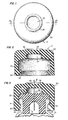
- A preferred embodiment is illustrated in the following figures of the drawing in which
- Fig. 1 is a plan view of the overcap herein.
- Fig. 2 is a vertical sectional view taken on line 2-2 of Fig. 1.
- Fig. 3 is a vertical sectional view of an assembly of a drug vial with the overcap of Figs. 1 and 2 applied thereto.
- with continuing reference to Figs. 1-3, there is depicted in Fig. 3 a
drug vial 10 having a closure consisting of arubber stopper 12 which is held to the vial finish by analuminum cap 14 having its plastic flip off portion removed to expose the stopper for piercing byneedle 16. Thealuminum cap 14 presents a substantially cylindrical surface for receiving the overcap of the invention. - The
overcap 17 of the invention includes a substantially cylindricaltop portion 20 having a vertical axis which as is shown in Fig. 3 is aligned with the vertical axis of the vial when the overcap has been applied. - Integral with the
top portion 20 and depending downwardly therefrom is an annularcross section skirt 22 having an inner surface substantially conforming to the contour of the outer surface of the closure and adapted to receive and press against said outer surface. Thus, the inner diameter of the skirt is equal to or slightly less than the outer diameter ofaluminum cap 14. - A
cylindrical chamber 24 is inset into the lower surface oftop portion 20 and has a vertical axis aligned with the vertical axis oftop portion 20. It has a depth to diameter ratio preferably ranging from about 0.25:1 to about 0.5:1 and typically has a diameter ranging from about 0.25 inches to about 0.5 inches. The depth to diameter ratio is very important because it allows the top of the overcap to be in proximity with the top of the drug container closure, e.g. 0.15 to 0.4 inches therefrom (not including the vertical dimension ofbead 36 discussed later) whereby there is substantially no increased risk of overturning due to the overcap. - An
annular shoulder 26 is defined intop portion 20 by the sidewall ofcylindrical chamber 24 and has a lower surface 28 (Fig. 2) defined by the lower surface oftop portion 20.Shoulder 26 has an inner diameter which is the same as the diameter ofchamber 24 and an outer diameter which is the same as the inner diameter ofskirt 22 and the ratio of its outer diameter to its inner diameter preferably ranges from about 1.75:1 to about 2.25:1. - An
annular locking flange 30 is integral with the bottom ofskirt 22 and has an inwardlyangled surface 32 providing circular access at the bottom of the overcap with a diameter greater than the outer diameter ofaluminum cap 14 and is angled upwardly, e.g. at 40 to 50 degrees, preferably at 45 degrees with the lower surface of the overcap and terminates in a vertical upper inner portion having an inside diameter corresponding approximately to the outside diameter of the neck ofvial 10. It has anupper surface 34 which provides a locking lip to engage againstaluminum cap 14 at the bottom of the container finish. - The dimension of the
surface 28 in the radial direction and the depth dimension ofskirt 22, i.e. the vertical distance between the outer margin ofsuface 28 andlip 34 as denoted by reference numberal 23, are selected to provide sufficient contact surface and the inner diameter and depth ofskirt 22 are selected to provide a pinching effect, i.e. a pressing effect againstcap 14, to prevent leakage between theovercap 17 and thecap 14. - An upstanding
annular bead 36 is part of and in the upper surface oftop portion 20 and is axially aligned with the vertical axis oftop portion 20. The bead is preferably semicircular in vertical cross section and preferably has a small radial dimension, e.g. 1/64 to 1/16 inch, very preferably 1/32 inch so as not to add materially to the vertical dimension of the overcap. Thebead 36 encircles and thereby defines acircular target area 38 for insertion through the overcap/of a hypodermic needle. Thetarget area 38 is centered over the cylindrical chamber 24.and on application of the overcap is centered over the target (puncture)area 40 ofstopper 12. The vertical dimension of the material of thetop portion 20 undertarget area 38, that is the distance between the top of thetop portion 20 at thetarget area 38 and the top ofchamber 24, is sufficiently small, e.g. 0.05-0.2 inches, and the material of construction of the overcap is such that thetop portion 10 attarget area 38 is readily punctured with a hypodermic recile. - The
overcap 17 is preferably constructed of natural rubber as natural rubbber has an elasticity such that with the aforedescribed dimensions, theovercap 17 is readily forced overstopper 12 andaluminum cap 14 by aligning theangled surface 32 over thestopper 12 andcap 14 and pushing downwardly, and such that with the aforedescribed dimen- sicns, thesurface 28 and inner surface of skirt 22 (along dimension 23) on application ofovercap 17 press againstcap 14 andstopper 12 and the finish ofvial 10 to prevent leakage between theovercap 17 andcap 14. Theovercap 17 car- also very appropriately be constructed of synthetic elastomers or a blend of natural rubber with synthetic elastomers but the elasticity should preferably be the same as or close to that of natural rubber. Examples of useful synthetic elastomers include those normally blended with natural rubber, e.g. polybutadiene, polystyrene-butadiene, necprene and terpolymer elastomer made from ethylene- prcpylene diene monomer (EPDM). - The overcap herein is readily made of one piece construction in a molding process.
- The overcap herein is utilized as follows: The
overcap 17 is positioned above thealuminum cap 14 which is in position overstopper 12 and the finish of a vial 10 (e.g. a 30cc. vial) which contains antineoplastic drug ready for reconstitution (the plastic flip top portion ofcap 14 has already been removed to exposestopper 12 so thatcap 14 andstopper 12 are as depicted in Fig. 3) and theangled surface 32 is positioned so as to overlie the portion ofcap 14 at the edge of the stopper. Then overcap 17 is pushed downwardly so as to fit over thecap 14 and so that lockinglip 34 engagescap 14 at a position under the container finish as depicted in Fig. 3. Then ahypodermic needle 16, e.g. an 18 gauge needle, which is associated with a syringe (not depicted), e.g. a 30 cc. B-D disposable syringe having the selected amount of diluent therein (e.g. 20 cc. of diluent) is positioned abovetarget area 38 approximately centrally oftarget area 38 so as also to be abovetarget area 40, and theneedle 16 is forced throughovercap 17 andstopper 12 so as to be in position as depicted in Fig. 3. Then the diluent is injected into thevial 10, e.g. in a single push. Despite the internal pressure created by the injection, theovercap 17 does not bulge or pop off. Theneedle 16 is then removed. Thevial 10 is then moved to swirl the liquid injected therein to dissolve the drug. Theneedle 16 is then reinserted and the syringe is then used to withdraw the reconstituted drug. Then theneedle 16 is withdrawn first fromstopper 12 and then fromovercap 17. As theneedle 16 is withdrawn, thestopper 12 andovercap 17 exert a wiping action to wipe residual drug therefrom so that it returns tovial 10 or tochamber 24. To the extent that drug is forced out ofvial 10 by the increased pressure due to initial injection of diluent, either during said injection c.r during dissolving/swirling or during withdrawal of reconstituted drug into the syringe or withdrawal of theneedLe 16 from thestopper 12 andovercap 17, it is trapped inchamber 24. There is no aerosoling of reconstituted drug into the environment or leakage betweenaluminum cap 14 andovercap 17. When the overap is needle punctured a second time and ir.jection is carried out whereby even 1.0 ml. solution mere enterschamber 24, there is no leakage out of the first puncture hole. - Testing is carried out on the
overcap 17 as follows. Theovercap 17, of one piece natural rubber molded construction is applied to a 30 cc. moldedflint glass vial 10 with 20 mm. finish with the plastic flip top portion ofcap 14 having already been removed. A 30 cc. B-D disposable syringe equipped with an 18gauge needle 16 and containing 20 cc. of water containing a blue die is positioned withneedle 16 above and centrally oftarget area 38 and is forced through theovercap 17 andstopper 12. Then the blue colored water is injected intovial 10 in a single push without regrard for pressure equalization. The needle is removed while a positive pressure remains invial 10. No visible spray is detected. When the aforedescribed injection is carried out withoutovercap 17 being used, a visible spray of aerosolized blue colored water is noted on withdrawal cf the needle. - In another test, the 18
gauge needle 16 is used to prenetrate theovercap 17 but not thestopper 12. Diluent is injected into the chamber in 0.25 cc. increments with inspection of the overcap equipped vial between injections for leakage at the puncture area and at the seal area betweenovercap 17 andcap 14. No leakage is observed until the fifth successive injection when leakage is noted in the seal area. - In another test the 18 gauge needle is used to puncture the overcap at the
target area 38 wherein the thickness is about 0.1 inch. The needle is then withdrawn. The needle is then inserted again at a second puncture point intarget area 38 and water is injected intochamber 24. No leakage is noted out of the first puncture passageway even though up to 1.0 ml. is injected intochamber 24 due to the elasticity and resiliency of the natural rubber material ofovercap 17. - While the foregoing describes preferred embodiments, modifications within the scope of the invention will be readily evident to those skilled in the art. Thus the scope of the invention is intended to be defined by the claims.
said cap being of a material having an elasticity substantially that of natural rubber so as to allow application over the closure and to provide sufficient pressure by the lower surface of the shoulder against the top outer portion of the closure and by the inner surface of the skirt against the outer surface of the closure to prevent leakage between said cap and said closure or container during reconstitution.
Claims (2)
said cap being of a material having an elasticity substantially that of natural rubber so as to allow application over the closure and to provide sufficient pressure by the lower surface of the shoulder against the top outer portion of the closure and by the inner surface of th skirt against the outer surface of the closure to prevent leakage between said cap and said closure or container during reconstitution.
Priority Applications (1)
| Application Number | Priority Date | Filing Date | Title |
|---|---|---|---|
| AT86104379T ATE64576T1 (en) | 1985-04-02 | 1986-04-01 | SAFETY SNAP CAP FOR PARENTERAL PRODUCTS HOLDING CONTAINERS. |
Applications Claiming Priority (2)
| Application Number | Priority Date | Filing Date | Title |
|---|---|---|---|
| US06/719,384 US4582207A (en) | 1985-04-02 | 1985-04-02 | Safety reservoir snap on overcap for parenteral drug container |
| US719384 | 1985-04-02 |
Publications (3)
| Publication Number | Publication Date |
|---|---|
| EP0197483A2 true EP0197483A2 (en) | 1986-10-15 |
| EP0197483A3 EP0197483A3 (en) | 1988-06-08 |
| EP0197483B1 EP0197483B1 (en) | 1991-06-19 |
Family
ID=24889864
Family Applications (1)
| Application Number | Title | Priority Date | Filing Date |
|---|---|---|---|
| EP86104379A Expired - Lifetime EP0197483B1 (en) | 1985-04-02 | 1986-04-01 | Safety reservoir snap on overcap for parenteral drug container |
Country Status (6)
| Country | Link |
|---|---|
| US (1) | US4582207A (en) |
| EP (1) | EP0197483B1 (en) |
| JP (1) | JPS61228865A (en) |
| AT (1) | ATE64576T1 (en) |
| CA (1) | CA1245602A (en) |
| DE (1) | DE3679848D1 (en) |
Cited By (1)
| Publication number | Priority date | Publication date | Assignee | Title |
|---|---|---|---|---|
| GB2187723B (en) * | 1986-03-13 | 1990-06-13 | Lyphomed Inc | Cover, especially for medicinal vial |
Families Citing this family (37)
| Publication number | Priority date | Publication date | Assignee | Title |
|---|---|---|---|---|
| US4882669A (en) * | 1983-11-28 | 1989-11-21 | Canon Kabushiki Kaisha | Multi computer fail safe control apparatus |
| JPS62253068A (en) * | 1986-04-25 | 1987-11-04 | 浪華ゴム工業株式会社 | Infusion container made of synthetic resin |
| IE60235B1 (en) * | 1986-09-18 | 1994-06-15 | Kabi Pharmacia Ab | "Connector and disposable assembly utilising said connector" |
| US4768568A (en) * | 1987-07-07 | 1988-09-06 | Survival Technology, Inc. | Hazardous material vial apparatus providing expansible sealed and filter vented chambers |
| JPS6442006A (en) * | 1987-08-08 | 1989-02-14 | Victor Company Of Japan | Production of magnetic head |
| JPH052198Y2 (en) * | 1987-12-29 | 1993-01-20 | ||
| US4886178A (en) * | 1988-04-27 | 1989-12-12 | Air Products And Chemicals, Inc. | Method and apparatus for packaging, shipping and using poisonous liquids |
| JPH0210842U (en) * | 1988-07-06 | 1990-01-24 | ||
| JPH02114056U (en) * | 1989-02-28 | 1990-09-12 | ||
| IT1229165B (en) * | 1989-04-07 | 1991-07-22 | Leopardi Francesco Paoletti Se | DEVICE FOR CLOSING VACUUM TUBES FOR BLOOD COLLECTION. |
| JP2923302B2 (en) * | 1989-05-17 | 1999-07-26 | テルモ株式会社 | Tubular body with diaphragm |
| US5100010A (en) * | 1990-11-08 | 1992-03-31 | The West Company, Incorporated | Containment seal assembly |
| US5232109A (en) * | 1992-06-02 | 1993-08-03 | Sterling Winthrop Inc. | Double-seal stopper for parenteral bottle |
| AU692756B2 (en) * | 1992-12-30 | 1998-06-18 | Abbott Laboratories | Thin diaphragm stopper for blunt entry device |
| FR2710039B1 (en) * | 1993-09-14 | 1995-11-03 | Cogema | Transport case container in a conduit. |
| FR2752820B1 (en) * | 1996-08-29 | 1998-09-25 | Oreal | DISTRIBUTION CAPSULE WITH IMPROVED SEALING |
| DE60031526T2 (en) * | 1999-05-14 | 2007-06-28 | Gen-Probe Inc., San Diego | THRUSTABLE CAP WITH INTERNAL TIP |
| US6716396B1 (en) | 1999-05-14 | 2004-04-06 | Gen-Probe Incorporated | Penetrable cap |
| US6341706B1 (en) | 2000-06-01 | 2002-01-29 | Color Access, Inc. | Snap-on plastic neck for glass containers |
| WO2002009636A1 (en) * | 2000-07-29 | 2002-02-07 | Sonita Stummer | Cap to be connected to a pouring device |
| US6893612B2 (en) | 2001-03-09 | 2005-05-17 | Gen-Probe Incorporated | Penetrable cap |
| JP4599035B2 (en) * | 2003-01-16 | 2010-12-15 | 株式会社日本シューター | Jug for sample transport |
| US20060253103A1 (en) * | 2005-05-09 | 2006-11-09 | Utterberg David S | Removable cap needle access site |
| US8092878B2 (en) * | 2006-04-17 | 2012-01-10 | West Pharmaceutical Services, Inc. | Cryogenic, elastomeric closure for cryogen containers |
| JP5566101B2 (en) * | 2006-04-24 | 2014-08-06 | メディカル・インスティル・テクノロジーズ・インコーポレイテッド | Needle penetrable and laser resealable freeze-drying apparatus and related methods |
| CA2834152C (en) * | 2006-05-25 | 2016-07-05 | Bayer Healthcare Llc | Reconstitution device |
| US8387810B2 (en) * | 2007-04-16 | 2013-03-05 | Becton, Dickinson And Company | Pierceable cap having piercing extensions for a sample container |
| US8387811B2 (en) | 2007-04-16 | 2013-03-05 | Bd Diagnostics | Pierceable cap having piercing extensions |
| US20150166219A1 (en) * | 2010-01-29 | 2015-06-18 | Integrity Products, Inc. | Perforable container cap |
| EP2415687B1 (en) * | 2009-03-30 | 2015-09-02 | Kinki University | Container plug |
| CN103957863B (en) * | 2011-10-20 | 2018-11-02 | 贝克顿·迪金森公司 | Hybrid element for container assemblies |
| US9808401B2 (en) | 2012-05-31 | 2017-11-07 | Kinki University | Exposure-preventing cap |
| US8925756B2 (en) * | 2012-08-08 | 2015-01-06 | Coravin, Inc. | Method and apparatus for gas cylinder sealing |
| CN104884026B (en) * | 2012-12-28 | 2018-04-24 | 株式会社Jms | Bottle shield |
| CN107613939B (en) * | 2015-04-30 | 2019-06-11 | 株式会社大塚制药工场 | The housing of medicine container |
| KR20240024370A (en) | 2017-07-27 | 2024-02-23 | 바이오메리욱스, 인코포레이티드. | Isolation tube |
| US11185617B2 (en) * | 2017-07-31 | 2021-11-30 | Becton, Dickinson And Company | Drainage system with retention ring |
Citations (3)
| Publication number | Priority date | Publication date | Assignee | Title |
|---|---|---|---|---|
| US4133441A (en) * | 1978-03-23 | 1979-01-09 | Baxter Travenol Laboratories, Inc. | Injection site |
| US4152269A (en) * | 1977-02-01 | 1979-05-01 | Warner-Lambert Company | Collection and separation device |
| US4465200A (en) * | 1983-06-06 | 1984-08-14 | Becton, Dickinson And Company | Low contamination closure for blood collection tubes |
Family Cites Families (16)
| Publication number | Priority date | Publication date | Assignee | Title |
|---|---|---|---|---|
| US1191567A (en) * | 1914-08-27 | 1916-07-18 | Jo Baily Brown | Bottle-closure. |
| US1554745A (en) * | 1923-10-09 | 1925-09-22 | Margaret H Mcmann | Closure for bottles and the like |
| US1857853A (en) * | 1930-02-10 | 1932-05-10 | Margaret H Mcmann | Closure for containers |
| US2364126A (en) * | 1941-12-09 | 1944-12-05 | Cantor Abraham | Receptacle closure |
| US3061131A (en) * | 1955-10-07 | 1962-10-30 | William H Robinson | Dual-purpose closure members |
| US3288320A (en) * | 1965-02-01 | 1966-11-29 | David L Swanson | Reusable bottle cap |
| US3484016A (en) * | 1968-05-06 | 1969-12-16 | Basic Products Dev Co | Container and closure |
| US3578037A (en) * | 1969-09-11 | 1971-05-11 | Thomas J Flynn | Method for filling a syringe |
| US4111326A (en) * | 1976-03-04 | 1978-09-05 | Becton, Dickinson And Company | Closure for air evacuated container |
| US4194640A (en) * | 1977-05-06 | 1980-03-25 | The Upjohn Company | Vial and closure |
| US4089432A (en) * | 1977-05-06 | 1978-05-16 | The Upjohn Company | Vial and closure |
| US4274543A (en) * | 1978-01-23 | 1981-06-23 | The Upjohn Company | Vial and closure structure |
| US4187893A (en) * | 1978-07-19 | 1980-02-12 | Abbott Laboratories | Combined additive and administration port for a container |
| US4267925A (en) * | 1979-10-01 | 1981-05-19 | The Upjohn Company | Closure for large-volume vial |
| US4441538A (en) * | 1979-12-26 | 1984-04-10 | Abbott Laboratories | Flexible container with integral ports and diaphragm |
| US4362250A (en) * | 1981-03-26 | 1982-12-07 | National Distillers & Chemical Corp. | Container for storing reactive or volatile material |
-
1985
- 1985-04-02 US US06/719,384 patent/US4582207A/en not_active Expired - Lifetime
-
1986
- 1986-02-19 CA CA000502165A patent/CA1245602A/en not_active Expired
- 1986-04-01 AT AT86104379T patent/ATE64576T1/en not_active IP Right Cessation
- 1986-04-01 DE DE8686104379T patent/DE3679848D1/en not_active Expired - Fee Related
- 1986-04-01 EP EP86104379A patent/EP0197483B1/en not_active Expired - Lifetime
- 1986-04-02 JP JP61076412A patent/JPS61228865A/en active Granted
Patent Citations (3)
| Publication number | Priority date | Publication date | Assignee | Title |
|---|---|---|---|---|
| US4152269A (en) * | 1977-02-01 | 1979-05-01 | Warner-Lambert Company | Collection and separation device |
| US4133441A (en) * | 1978-03-23 | 1979-01-09 | Baxter Travenol Laboratories, Inc. | Injection site |
| US4465200A (en) * | 1983-06-06 | 1984-08-14 | Becton, Dickinson And Company | Low contamination closure for blood collection tubes |
Cited By (1)
| Publication number | Priority date | Publication date | Assignee | Title |
|---|---|---|---|---|
| GB2187723B (en) * | 1986-03-13 | 1990-06-13 | Lyphomed Inc | Cover, especially for medicinal vial |
Also Published As
| Publication number | Publication date |
|---|---|
| EP0197483B1 (en) | 1991-06-19 |
| JPS61228865A (en) | 1986-10-13 |
| EP0197483A3 (en) | 1988-06-08 |
| CA1245602A (en) | 1988-11-29 |
| DE3679848D1 (en) | 1991-07-25 |
| ATE64576T1 (en) | 1991-07-15 |
| US4582207A (en) | 1986-04-15 |
| JPH0588142B2 (en) | 1993-12-21 |
Similar Documents
| Publication | Publication Date | Title |
|---|---|---|
| EP0197483B1 (en) | Safety reservoir snap on overcap for parenteral drug container | |
| US5060812A (en) | Medication container stopper which can be punctured by nozzle of a hypodermic syringe | |
| JP2954550B2 (en) | Connector assembly | |
| US9345642B2 (en) | Vial adapter for a needle-free syringe | |
| CA1058035A (en) | Disposable two-compartment syringe | |
| US6695829B2 (en) | Container closure system | |
| US6692478B1 (en) | Swabbable needleless vial access | |
| JPH0533058B2 (en) | ||
| AU650122B2 (en) | Improved liquid dispensers | |
| EP1339372B1 (en) | Axially activated vial access adapter | |
| CA1239619A (en) | Reconstitution device | |
| US4484916A (en) | Medical solution container and port construction | |
| US5036992A (en) | Medicine vial cap for needleless syringe | |
| EP1029526A1 (en) | Medicament container stopper with integral spike access means | |
| EP3366268A1 (en) | Seal system for cannula | |
| JPH11104215A (en) | Glass bottle connector assembly | |
| US20070208296A1 (en) | Syringe Safety Device | |
| MXPA02009726A (en) | Pre-filled syringe. | |
| CA1054472A (en) | Medicament additive system | |
| JP2001513682A (en) | Container cap assembly with closed penetrator | |
| JP2859833B2 (en) | Protective cap device for medical device passage | |
| US5379907A (en) | Stopper for medication container | |
| US11730678B2 (en) | Secured medication transfer system | |
| US4267925A (en) | Closure for large-volume vial | |
| US11872187B1 (en) | Tamper evident seal for a vial cover |
Legal Events
| Date | Code | Title | Description |
|---|---|---|---|
| PUAI | Public reference made under article 153(3) epc to a published international application that has entered the european phase |
Free format text: ORIGINAL CODE: 0009012 |
|
| AK | Designated contracting states |
Kind code of ref document: A2 Designated state(s): AT BE CH DE FR GB IT LI LU NL SE |
|
| PUAL | Search report despatched |
Free format text: ORIGINAL CODE: 0009013 |
|
| AK | Designated contracting states |
Kind code of ref document: A3 Designated state(s): AT BE CH DE FR GB IT LI LU NL SE |
|
| 17P | Request for examination filed |
Effective date: 19881129 |
|
| RAP1 | Party data changed (applicant data changed or rights of an application transferred) |
Owner name: BRISTOL-MYERS SQUIBB COMPANY (A DELAWARE CORP.) |
|
| 17Q | First examination report despatched |
Effective date: 19900515 |
|
| GRAA | (expected) grant |
Free format text: ORIGINAL CODE: 0009210 |
|
| AK | Designated contracting states |
Kind code of ref document: B1 Designated state(s): AT BE CH DE FR GB IT LI LU NL SE |
|
| REF | Corresponds to: |
Ref document number: 64576 Country of ref document: AT Date of ref document: 19910715 Kind code of ref document: T |
|
| ET | Fr: translation filed | ||
| REF | Corresponds to: |
Ref document number: 3679848 Country of ref document: DE Date of ref document: 19910725 |
|
| ITF | It: translation for a ep patent filed |
Owner name: MODIANO & ASSOCIATI S.R.L. |
|
| PLBE | No opposition filed within time limit |
Free format text: ORIGINAL CODE: 0009261 |
|
| STAA | Information on the status of an ep patent application or granted ep patent |
Free format text: STATUS: NO OPPOSITION FILED WITHIN TIME LIMIT |
|
| 26N | No opposition filed | ||
| EPTA | Lu: last paid annual fee | ||
| EAL | Se: european patent in force in sweden |
Ref document number: 86104379.2 |
|
| PGFP | Annual fee paid to national office [announced via postgrant information from national office to epo] |
Ref country code: DE Payment date: 20000327 Year of fee payment: 15 |
|
| PGFP | Annual fee paid to national office [announced via postgrant information from national office to epo] |
Ref country code: GB Payment date: 20000329 Year of fee payment: 15 |
|
| PGFP | Annual fee paid to national office [announced via postgrant information from national office to epo] |
Ref country code: SE Payment date: 20000406 Year of fee payment: 15 |
|
| PGFP | Annual fee paid to national office [announced via postgrant information from national office to epo] |
Ref country code: LU Payment date: 20000411 Year of fee payment: 15 Ref country code: FR Payment date: 20000411 Year of fee payment: 15 |
|
| PGFP | Annual fee paid to national office [announced via postgrant information from national office to epo] |
Ref country code: AT Payment date: 20000412 Year of fee payment: 15 |
|
| PGFP | Annual fee paid to national office [announced via postgrant information from national office to epo] |
Ref country code: CH Payment date: 20000414 Year of fee payment: 15 |
|
| PGFP | Annual fee paid to national office [announced via postgrant information from national office to epo] |
Ref country code: NL Payment date: 20000428 Year of fee payment: 15 |
|
| PGFP | Annual fee paid to national office [announced via postgrant information from national office to epo] |
Ref country code: BE Payment date: 20000622 Year of fee payment: 15 |
|
| PG25 | Lapsed in a contracting state [announced via postgrant information from national office to epo] |
Ref country code: LU Free format text: LAPSE BECAUSE OF NON-PAYMENT OF DUE FEES Effective date: 20010401 Ref country code: GB Free format text: LAPSE BECAUSE OF NON-PAYMENT OF DUE FEES Effective date: 20010401 Ref country code: AT Free format text: LAPSE BECAUSE OF NON-PAYMENT OF DUE FEES Effective date: 20010401 |
|
| PG25 | Lapsed in a contracting state [announced via postgrant information from national office to epo] |
Ref country code: SE Free format text: LAPSE BECAUSE OF NON-PAYMENT OF DUE FEES Effective date: 20010402 |
|
| PG25 | Lapsed in a contracting state [announced via postgrant information from national office to epo] |
Ref country code: LI Free format text: LAPSE BECAUSE OF NON-PAYMENT OF DUE FEES Effective date: 20010430 Ref country code: FR Free format text: THE PATENT HAS BEEN ANNULLED BY A DECISION OF A NATIONAL AUTHORITY Effective date: 20010430 Ref country code: CH Free format text: LAPSE BECAUSE OF NON-PAYMENT OF DUE FEES Effective date: 20010430 Ref country code: BE Free format text: LAPSE BECAUSE OF NON-PAYMENT OF DUE FEES Effective date: 20010430 |
|
| BERE | Be: lapsed |
Owner name: BRISTOL-MYERS SQUIBB CY Effective date: 20010430 |
|
| PG25 | Lapsed in a contracting state [announced via postgrant information from national office to epo] |
Ref country code: NL Free format text: LAPSE BECAUSE OF NON-PAYMENT OF DUE FEES Effective date: 20011101 |
|
| GBPC | Gb: european patent ceased through non-payment of renewal fee |
Effective date: 20010401 |
|
| EUG | Se: european patent has lapsed |
Ref document number: 86104379.2 |
|
| REG | Reference to a national code |
Ref country code: CH Ref legal event code: PL |
|
| NLV4 | Nl: lapsed or anulled due to non-payment of the annual fee |
Effective date: 20011101 |
|
| PG25 | Lapsed in a contracting state [announced via postgrant information from national office to epo] |
Ref country code: DE Free format text: LAPSE BECAUSE OF NON-PAYMENT OF DUE FEES Effective date: 20020201 |
|
| REG | Reference to a national code |
Ref country code: FR Ref legal event code: ST |
|
| PG25 | Lapsed in a contracting state [announced via postgrant information from national office to epo] |
Ref country code: IT Free format text: LAPSE BECAUSE OF NON-PAYMENT OF DUE FEES;WARNING: LAPSES OF ITALIAN PATENTS WITH EFFECTIVE DATE BEFORE 2007 MAY HAVE OCCURRED AT ANY TIME BEFORE 2007. THE CORRECT EFFECTIVE DATE MAY BE DIFFERENT FROM THE ONE RECORDED. Effective date: 20050401 |