EP0195428A2 - Apparatus and method for producing weighed batches of aligned elongated articles - Google Patents
Apparatus and method for producing weighed batches of aligned elongated articles Download PDFInfo
- Publication number
- EP0195428A2 EP0195428A2 EP86103699A EP86103699A EP0195428A2 EP 0195428 A2 EP0195428 A2 EP 0195428A2 EP 86103699 A EP86103699 A EP 86103699A EP 86103699 A EP86103699 A EP 86103699A EP 0195428 A2 EP0195428 A2 EP 0195428A2
- Authority
- EP
- European Patent Office
- Prior art keywords
- articles
- alignment
- container
- batch
- accordance
- Prior art date
- Legal status (The legal status is an assumption and is not a legal conclusion. Google has not performed a legal analysis and makes no representation as to the accuracy of the status listed.)
- Granted
Links
Images

Classifications
-
- B—PERFORMING OPERATIONS; TRANSPORTING
- B65—CONVEYING; PACKING; STORING; HANDLING THIN OR FILAMENTARY MATERIAL
- B65B—MACHINES, APPARATUS OR DEVICES FOR, OR METHODS OF, PACKAGING ARTICLES OR MATERIALS; UNPACKING
- B65B1/00—Packaging fluent solid material, e.g. powders, granular or loose fibrous material, loose masses of small articles, in individual containers or receptacles, e.g. bags, sacks, boxes, cartons, cans, or jars
- B65B1/30—Devices or methods for controlling or determining the quantity or quality or the material fed or filled
- B65B1/32—Devices or methods for controlling or determining the quantity or quality or the material fed or filled by weighing
- B65B1/34—Adjusting weight by trickle feed
-
- B—PERFORMING OPERATIONS; TRANSPORTING
- B65—CONVEYING; PACKING; STORING; HANDLING THIN OR FILAMENTARY MATERIAL
- B65B—MACHINES, APPARATUS OR DEVICES FOR, OR METHODS OF, PACKAGING ARTICLES OR MATERIALS; UNPACKING
- B65B19/00—Packaging rod-shaped or tubular articles susceptible to damage by abrasion or pressure, e.g. cigarettes, cigars, macaroni, spaghetti, drinking straws or welding electrodes
- B65B19/34—Packaging other rod-shaped articles, e.g. sausages, macaroni, spaghetti, drinking straws, welding electrodes
-
- B—PERFORMING OPERATIONS; TRANSPORTING
- B65—CONVEYING; PACKING; STORING; HANDLING THIN OR FILAMENTARY MATERIAL
- B65B—MACHINES, APPARATUS OR DEVICES FOR, OR METHODS OF, PACKAGING ARTICLES OR MATERIALS; UNPACKING
- B65B35/00—Supplying, feeding, arranging or orientating articles to be packaged
- B65B35/30—Arranging and feeding articles in groups
- B65B35/34—Arranging and feeding articles in groups by agitators or vibrators
-
- B—PERFORMING OPERATIONS; TRANSPORTING
- B65—CONVEYING; PACKING; STORING; HANDLING THIN OR FILAMENTARY MATERIAL
- B65B—MACHINES, APPARATUS OR DEVICES FOR, OR METHODS OF, PACKAGING ARTICLES OR MATERIALS; UNPACKING
- B65B61/00—Auxiliary devices, not otherwise provided for, for operating on sheets, blanks, webs, binding material, containers or packages
- B65B61/28—Auxiliary devices, not otherwise provided for, for operating on sheets, blanks, webs, binding material, containers or packages for discharging completed packages from machines
-
- G—PHYSICS
- G01—MEASURING; TESTING
- G01G—WEIGHING
- G01G19/00—Weighing apparatus or methods adapted for special purposes not provided for in the preceding groups
- G01G19/387—Weighing apparatus or methods adapted for special purposes not provided for in the preceding groups for combinatorial weighing, i.e. selecting a combination of articles whose total weight or number is closest to a desired value
- G01G19/393—Weighing apparatus or methods adapted for special purposes not provided for in the preceding groups for combinatorial weighing, i.e. selecting a combination of articles whose total weight or number is closest to a desired value using two or more weighing units
Definitions
- the apparatus and method of the present invention relates generally to the separation, weighing, and selecting a combination of selected groups of elongated articles to form a batch of articles of predetermined weight, followed by the alignment of the articles in such batch and packaging of such batch of aligned articles.
- the invention is related to such an apparatus and method in which successive batches of elongated articles are aligned by different alignment systems mounted on a common rotating support.
- Each alignment system includes a plurality of vibrating conveyor stages which prealign the articles with their axes parallel to the direction of travel before feeding them into an alignment container.
- the batch of articles are compacted and further aligned in the alignment container with their longitudinal axis substantialy parallel, before the aligned batch of articles is discharged from such container into a packaging machine where such batch is packaged without disturbing such alignment.
- the apparatus and method of the present invention is especially useful in producing weighed batches of aligned elongated food products, such as french fry potato strips.
- Another object of the invention is to provide such an apparatus and method with a high capacity alignment mechanism including a plurality of alignment systems mounted on a common rotating support for selectively positioning the input stage of each alignment system beneath the output of a common collector container supplying the weighed batches.
- a further object of the invention is to provide such ah apparatus and method in which the alignment systems each have an alignment container for aligning and compacting the elongated articles into a weighed and aligned batch of articles which is discharged from the alignment container into a packaging machine for packaging without disturbing such alignment in order to provide a compact package of aligned articles which occupy less space during shipping and storage.
- An additional object of the invention is to provide such an apparatus-and method in which the batches of predetermined weight are produced in an accurate and efficient manner by selectively discharging different combinations of scale buckets containing weighed groups of such articles into a common container to provide a batch of articles of a predetermined weight automatically.
- Still another object of the invention is to provide such an apparatus and method in which each of the alignment systems each include a plurality of vibrating conveyor stages by which the elongated articles are prealigned with their longitudinal axes substantially parallel to their direction of travel before they are fed into the alignment container.
- a still further object of the present invention is to provide such an apparatus and method in which the batch of aligned articles is transferred from a vibrating alignment container through a transfer tube to the bagging machine without jamming by providing a flexible mounted connector tube between the bottom of the alignment container and the transfer tube.
- a preferred embodiment of the apparatus and method of the present invention includes a supply hopper 10 containing a supply of the elongated articles, such as french fry potato strips, or other elongated food products.
- the articles are discharged from the supply hopper 10 onto the upper surface of a separator cone 12 which is vibrated by a vibrating mechanism 13 in the manner described in U.S. Patent 4,398,612 cited above.
- the separator cone Upon separation by the separator cone, the articles are fed into ten separator containers 14 through associated transfer feeders 15 to form groups of articles in such separator containers.
- the transfer feeders 15 are also vibrated in the manner described in such patent for conveying such articles.
- the groups of articles in the separator containers 14 are dumped into ten different weighing containers or scale buckets 16 which are each associated with ten different electronic weighing scales 18 spaced radially outward therefrom.
- the electronic scales 18 each produce electrical signal corresponding to the weight of the group of articles in the bucket 16 and transmit such weight signal to an input te'rminal 17-of a computer 19.
- Computer 19 may be a digital microprocessor which processes the weight signals to produce gate control signals on outputs 21 for selectively discharging the buckets 16 into a common collector container 20 beneath such buckets.
- the dump gates 22 at the bottom ends of the scale buckets 16 are selectively opened by the gate control signals on computer outputs 21 in order to selectively discharge the groups of articles in such buckets in different combinations of weights which will total a predetermined weight to provide the batch of articles in the common collector container 20 in the manner of U.S. Patent 4,398,612 cited above.
- a batch gate 24 at the bottom of the common collector container 20 is opened by a batch output signal on a computer output 23 to discharge the batch of articles into one of eight alignment systems 25.
- Each of the alignment systems includes three vibration conveyor stages including an input conveyor stage 26, an intermediate conveyor stage 28 and an output conveyor stage 30.
- the elongated articles are prealigned with their longitudinal axes substantially parallel to their direction of travel along such conveyor stages.
- Each of these conveyor stages is a vibrating conveyor of the type shown in my copending U.S. patent application Serial No. 376,515.
- the output conveyor stage 30 discharges the articles after they are prealigned by such conveyor stages into an alignment container 32, in a manner hereafter described with respect to Figs. 5 and 6.
- the eight conveyor systems 25 are mounted on a common support frame 34 which is rotated about an axis of rotation 36 by an electric drive motor 38 connected to a gear train 40 by a coupling chain or belt 42.
- the support frame 34 and the alignment systems 25 mounted thereon rotate in the clockwise direction of arrow 44 in Fig. 3 about the axis of rotation 36 with an intermittent motion.
- the input stage 26A of one selected alignment system is positioned beneath the batch gate 24 of the collector container 20 in the load position.
- the support frame 34 and such conveyor systems are rotated 45 degrees about the axis of rotation 36 until the input stage of a second alignment system is positioned under the batch gate 24 for discharge of another batch onto the second system.
- the first alignment system is rotated a total of 360 degrees while it vibrates the articles on the conveyor stages 26, 28 and 30 and feeds such articles into the alignment container 32, until the alignment container of such first alignment system is in the unload position 32A shown in Fig. 3.
- the aligned articles are discharged as a batch from such alignment container into the bag machine, as hereafter discussed with respect to Fig. 4.
- the elongated articles are transported from the input conveyor atage 26A through the intermediate conveyor stage 28A, and the output conveyor stage 30A by vibration causing such elongated articles to be prealigned with their longitudinal axis substantially parallel to their direction of travel when they reach the end of the output conveyor stage.
- the prealigned articles are discharged into the alignment container 32 by the time such alignment system has rotated 360° about axis 36.
- the frame 36 is provided with 45 degree intermittent rotation so that each input conveyor stage 26 of the eight conveyor systems is momentarily stopped in the load position 26A of Fig. 3 for loading of the batches.
- such 45 degree intermittent rotation allows the aligned articles in the alignment container 32 of each alignment system to be discharged as an aligned batch into the bagging machine at the unload position 32A of Fig. 3.
- the alignment container 32 is supported by top and bottom mounting backets 46 and 48 on spring shock mounts 50 and 52 fastened to a vibrator member 54 which is vibrated by a vibration motor 56 coupled thereto.
- the alignment container .32 is vibrated to further compact and align the elongated articles after they are dropped from the end of output conveyor stage 30 into the top of such alignment container.
- a discharge gate closes the bottom of the alignment container including a pair of gate doors 58 pivotally mounted to the bottom ends of the alignment container at pivots 60.
- the gate doors 58 are opened by a cylinder 62 controlled by an unload signal produced by the computer 19 of Fig. 1 at an unload output 64.
- the weighed and aligned batch of articles is discharged from the alignement container 32A through the discharge gate 58 into a transfer tube 66, which is coupled by a connector tube 68 to the bottom of such alignment container.
- the transfer tube is attached to the connector tube by a flexible coupling 70, such as a rubber strip mount, which enables vibration of the connector tube 68 due to contact with the vibrating alignment container while maintaining such connector tube 68 connected to the transfer tube during discharge.
- a packaging mechanism having an input chamber 72 is provided in alignment with the transfer tube 66 for packaging the weighed aligned batch of elongated articles when they are transferred as a batch from the alignment container through the transfer tube into such packaging mechanism without disturbing their alignment.
- One suitable packaging mechanism is shown in copending application Serial No. 376,515.
- the packaging mechanism 72 may be mounted beneath a base support deck 74 supporting the frame 34 for the rotating alignment systems.
- the transfer tube 66 extends through a passageway 76 in such deck as shown in Fig. 1.
- the scale and separator mechanism are mounted on a pair of support beams 78 above the support deck 74 with the batch gate 24 at the bottom of the collector container 20 in alignment with the input conveyor stage in load position 26A, which is displaced from the axis of rotation 36 of the alignment mechanism frame 34, as shown in Figs. 2 and 3.
- the alignment conveyor stages 26, 28 and 30 are vibrating conveyors of the type shown in my copending U.S. patent application Serial No. 376,515 which prealign the elongated articles 80 so that their longitudinal axes 88 are substantially parallel to their direction of travel 82 on the output conveyor stage 30.
- the output conveyor stage 30 is provided with a plurality of longitudinal partitions 84 which divide the output conveyor into a plurality of parallel channels each having a width W which is less than the length Y of the elongated article, as shown in Fig. 6.
- the output conveyor stage 30 terminates above the top of the alignment container 32 at the front edge of such alignment container, so that the elongated articles 80 traveling in the direction 82 parallel to partitions 84 strike the rear wall 86 of such container at an acute angle 6 of about 45 degrees, as shown in Fig. 6.
- the width Z of the container 32 is equal to X sine 8 where X is the distance from the front edge to the rear wall 86 of such container along the direction 82.
- the distance X is less than one-half the length Y of the elongated article.
- the elongated article 80 does not fall into the container until its front end strikes the rear wall 86 of the container.
Abstract
Description
- The present patent application is a continuation-in-part of pending U.S. patent application Serial No. 376,515, filed May 10, 1982 entitled "Apparatus and Method for Aligning and Packaging Elongated Articles".
- The apparatus and method of the present invention relates generally to the separation, weighing, and selecting a combination of selected groups of elongated articles to form a batch of articles of predetermined weight, followed by the alignment of the articles in such batch and packaging of such batch of aligned articles. In particular, the invention is related to such an apparatus and method in which successive batches of elongated articles are aligned by different alignment systems mounted on a common rotating support. Each alignment system includes a plurality of vibrating conveyor stages which prealign the articles with their axes parallel to the direction of travel before feeding them into an alignment container. The batch of articles are compacted and further aligned in the alignment container with their longitudinal axis substantialy parallel, before the aligned batch of articles is discharged from such container into a packaging machine where such batch is packaged without disturbing such alignment. The apparatus and method of the present invention is especially useful in producing weighed batches of aligned elongated food products, such as french fry potato strips.
- Previously it has been proposed in U.S. Patent 4,398,612 of Mikami et al issued August 16, 1983 entitled "Automatic Weighing Apparatus" to provide a separator and scale apparatus for separating a plurality of articles into groups of articles which are fed into scale buckets for weighing such groups. The weighed groups of articles are automatically selectively combined by discharging some of such groups from the scale buckets into a common container chute to provide a batch of articles of predetermined weight in such chute which is discharged into a packaging machine. However, unlike the present invention, there is no alignment system for aligning elongated articles in the weighed batch of articles in the manner of the present invention.
- Similar separator and scale apparatus is shown in U.S. Patent 4,465,150 of Matsumoto, issued August 14, 1984 and U.S. Patent 4,467,880 of Minamida et al, issued August 28, 1984, which are both assigned to the same assignee as the previously mentioned Mikami et al patent. This prior art apparatus employs a computer for selecting those weighed groups of articles which are combined to form a batch of predetermined weight by selectively discharging the scale buckets using computer generated gate signals as shown in U.S. Patent 4,398,612 cited above.
- It is therefore one object of the present invention to provide an improved apparatus and method for producing weighed batches of aligned elongated articles in a fast and efficient manner.
- Another object of the invention is to provide such an apparatus and method with a high capacity alignment mechanism including a plurality of alignment systems mounted on a common rotating support for selectively positioning the input stage of each alignment system beneath the output of a common collector container supplying the weighed batches.
- A further object of the invention is to provide such ah apparatus and method in which the alignment systems each have an alignment container for aligning and compacting the elongated articles into a weighed and aligned batch of articles which is discharged from the alignment container into a packaging machine for packaging without disturbing such alignment in order to provide a compact package of aligned articles which occupy less space during shipping and storage.
- An additional object of the invention is to provide such an apparatus-and method in which the batches of predetermined weight are produced in an accurate and efficient manner by selectively discharging different combinations of scale buckets containing weighed groups of such articles into a common container to provide a batch of articles of a predetermined weight automatically.
- Still another object of the invention is to provide such an apparatus and method in which each of the alignment systems each include a plurality of vibrating conveyor stages by which the elongated articles are prealigned with their longitudinal axes substantially parallel to their direction of travel before they are fed into the alignment container.
- A still further object of the present invention is to provide such an apparatus and method in which the batch of aligned articles is transferred from a vibrating alignment container through a transfer tube to the bagging machine without jamming by providing a flexible mounted connector tube between the bottom of the alignment container and the transfer tube.
- Other objects and advantages of the present invention will be apparent from the following detailed description of a preferred embodiment thereof, and from the attached drawings of which:
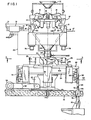
- Fig. 1 is a front view of the preferred embodiment of the apparatus of the present invention;
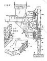
- Fig. 2 is an enlarged side elevation view taken along the line 2-2 of Fig. 1;
- Fig. 3 is a horizontal section view taken along the line 3-3 of Fig. 1 showing a plurality of alignment systems mounted on a common rotating support beneath the outlet of the common batch container of Fig. 2;
- Fig. 4 is an enlarged horizontal section view taken along the line 4-4 of Fig. 3;
- Fig. 5 is an enlarged view of one of the alignment systems of Fig. 3; and
- Fig. 6 is an enlarged view of the output end of the alignment system of Fig. 5 showing discharge of an aligned elongated article into the alignment container.
- As shown in Fig. 1, a preferred embodiment of the apparatus and method of the present invention includes a
supply hopper 10 containing a supply of the elongated articles, such as french fry potato strips, or other elongated food products. The articles are discharged from thesupply hopper 10 onto the upper surface of aseparator cone 12 which is vibrated by a vibratingmechanism 13 in the manner described in U.S. Patent 4,398,612 cited above. Upon separation by the separator cone, the articles are fed into tenseparator containers 14 through associatedtransfer feeders 15 to form groups of articles in such separator containers. Thetransfer feeders 15 are also vibrated in the manner described in such patent for conveying such articles. The groups of articles in theseparator containers 14 are dumped into ten different weighing containers orscale buckets 16 which are each associated with ten differentelectronic weighing scales 18 spaced radially outward therefrom. Theelectronic scales 18 each produce electrical signal corresponding to the weight of the group of articles in thebucket 16 and transmit such weight signal to an input te'rminal 17-of acomputer 19.Computer 19 may be a digital microprocessor which processes the weight signals to produce gate control signals onoutputs 21 for selectively discharging thebuckets 16 into acommon collector container 20 beneath such buckets. Thus, thedump gates 22 at the bottom ends of thescale buckets 16 are selectively opened by the gate control signals oncomputer outputs 21 in order to selectively discharge the groups of articles in such buckets in different combinations of weights which will total a predetermined weight to provide the batch of articles in thecommon collector container 20 in the manner of U.S. Patent 4,398,612 cited above. - A
batch gate 24 at the bottom of thecommon collector container 20 is opened by a batch output signal on acomputer output 23 to discharge the batch of articles into one of eightalignment systems 25. Each of the alignment systems includes three vibration conveyor stages including aninput conveyor stage 26, anintermediate conveyor stage 28 and anoutput conveyor stage 30. During movement along the vibrating conveyor stages, the elongated articles are prealigned with their longitudinal axes substantially parallel to their direction of travel along such conveyor stages. Each of these conveyor stages is a vibrating conveyor of the type shown in my copending U.S. patent application Serial No. 376,515. Theoutput conveyor stage 30 discharges the articles after they are prealigned by such conveyor stages into analignment container 32, in a manner hereafter described with respect to Figs. 5 and 6. - As shown in Figs. 2 and 3, the eight
conveyor systems 25 are mounted on acommon support frame 34 which is rotated about an axis ofrotation 36 by anelectric drive motor 38 connected to agear train 40 by a coupling chain orbelt 42. As a result, thesupport frame 34 and thealignment systems 25 mounted thereon rotate in the clockwise direction of arrow 44 in Fig. 3 about the axis ofrotation 36 with an intermittent motion. As a result, theinput stage 26A of one selected alignment system is positioned beneath thebatch gate 24 of thecollector container 20 in the load position. After the weighed batch of articles is dumped from thecollector container 20 onto theinput stage 26 of the first conveyor system, thesupport frame 34 and such conveyor systems are rotated 45 degrees about the axis ofrotation 36 until the input stage of a second alignment system is positioned under thebatch gate 24 for discharge of another batch onto the second system. The first alignment system is rotated a total of 360 degrees while it vibrates the articles on theconveyor stages alignment container 32, until the alignment container of such first alignment system is in theunload position 32A shown in Fig. 3. At this time the aligned articles are discharged as a batch from such alignment container into the bag machine, as hereafter discussed with respect to Fig. 4. - The elongated articles are transported from the
input conveyor atage 26A through theintermediate conveyor stage 28A, and theoutput conveyor stage 30A by vibration causing such elongated articles to be prealigned with their longitudinal axis substantially parallel to their direction of travel when they reach the end of the output conveyor stage. The prealigned articles are discharged into thealignment container 32 by the time such alignment system has rotated 360° aboutaxis 36. It should be noted that theframe 36 is provided with 45 degree intermittent rotation so that eachinput conveyor stage 26 of the eight conveyor systems is momentarily stopped in theload position 26A of Fig. 3 for loading of the batches. Similarly, such 45 degree intermittent rotation allows the aligned articles in thealignment container 32 of each alignment system to be discharged as an aligned batch into the bagging machine at theunload position 32A of Fig. 3. - As shown in Fig. 4, the
alignment container 32 is supported by top andbottom mounting backets 46 and 48 onspring shock mounts 50 and 52 fastened to avibrator member 54 which is vibrated by avibration motor 56 coupled thereto. As a result, the alignment container .32 is vibrated to further compact and align the elongated articles after they are dropped from the end ofoutput conveyor stage 30 into the top of such alignment container. A discharge gate closes the bottom of the alignment container including a pair ofgate doors 58 pivotally mounted to the bottom ends of the alignment container atpivots 60. Thegate doors 58 are opened by acylinder 62 controlled by an unload signal produced by thecomputer 19 of Fig. 1 at anunload output 64. The weighed and aligned batch of articles is discharged from thealignement container 32A through thedischarge gate 58 into atransfer tube 66, which is coupled by aconnector tube 68 to the bottom of such alignment container. The transfer tube is attached to the connector tube by aflexible coupling 70, such as a rubber strip mount, which enables vibration of theconnector tube 68 due to contact with the vibrating alignment container while maintainingsuch connector tube 68 connected to the transfer tube during discharge. - As shown in Fig. 1, a packaging mechanism having an
input chamber 72 is provided in alignment with thetransfer tube 66 for packaging the weighed aligned batch of elongated articles when they are transferred as a batch from the alignment container through the transfer tube into such packaging mechanism without disturbing their alignment. One suitable packaging mechanism is shown in copending application Serial No. 376,515. Thepackaging mechanism 72 may be mounted beneath abase support deck 74 supporting theframe 34 for the rotating alignment systems. In this case, thetransfer tube 66 extends through apassageway 76 in such deck as shown in Fig. 1. It should be noted that the scale and separator mechanism are mounted on a pair ofsupport beams 78 above thesupport deck 74 with thebatch gate 24 at the bottom of thecollector container 20 in alignment with the input conveyor stage inload position 26A, which is displaced from the axis ofrotation 36 of thealignment mechanism frame 34, as shown in Figs. 2 and 3. - As shown in Figs. 5 and 6, the alignment conveyor stages 26, 28 and 30 are vibrating conveyors of the type shown in my copending U.S. patent application Serial No. 376,515 which prealign the
elongated articles 80 so that theirlongitudinal axes 88 are substantially parallel to their direction oftravel 82 on theoutput conveyor stage 30.. Theoutput conveyor stage 30 is provided with a plurality oflongitudinal partitions 84 which divide the output conveyor into a plurality of parallel channels each having a width W which is less than the length Y of the elongated article, as shown in Fig. 6. Theoutput conveyor stage 30 terminates above the top of thealignment container 32 at the front edge of such alignment container, so that theelongated articles 80 traveling in thedirection 82 parallel topartitions 84 strike therear wall 86 of such container at an acute angle 6 of about 45 degrees, as shown in Fig. 6. The width Z of thecontainer 32 is equal to X sine 8 where X is the distance from the front edge to therear wall 86 of such container along thedirection 82. The distance X is less than one-half the length Y of the elongated article. As a result, theelongated article 80 does not fall into the container until its front end strikes therear wall 86 of the container. - Since the
elongated articles 80 are prealigned with theirlongitudinal axes 88 parallel to theirtravel direction 82, such articles strike therear wall 86 at angle 6 and slide along the wall into the dashed line position 80' of Fig. 6 until more than half the length of such article lies over the opening of the alignment container. Then the articles fall down into such alignment:container, since their center of gravity is over the top opening of such alignment container. The longitudinal axis 88' of thearticle 80 is thereby moved into an aligned position generally parallel to therear wall 86 of the alignment container after such article falls into such alignment container. In addition, due to vibration of thealignment container 32 by thevibrator motor 56, a more complete parallel alignment of the longitudinal axis 88' of the articles within such alignment container takes place as well as a compacting of the articles. The result is that the articles are discharged from the bottom of the alignment container as a compact, aligned and weighed batch of articles to thepackaging mechanism 72 where such batch is packaged. This is an improvement over conventional packaging of elongated articles, such as. french fry potatoes, with random orientation to provide a larger package which requires much more space during shipment and storage than the packages of the aligned and weighed batches of articles produced in accordance with the present invention. - It will be obvious to those having ordinary skill in the art that many changes may be made in the above described preferred embodiment of the present invention. Therefore, the scope of the present invention should be determined by the following claims.
Claims (20)
Applications Claiming Priority (2)
| Application Number | Priority Date | Filing Date | Title |
|---|---|---|---|
| US714163 | 1985-03-19 | ||
| US06/714,163 US4629017A (en) | 1982-05-10 | 1985-03-19 | Apparatus and method for producing weighed batches of aligned elongated articles |
Publications (3)
| Publication Number | Publication Date |
|---|---|
| EP0195428A2 true EP0195428A2 (en) | 1986-09-24 |
| EP0195428A3 EP0195428A3 (en) | 1987-10-28 |
| EP0195428B1 EP0195428B1 (en) | 1989-10-18 |
Family
ID=24868974
Family Applications (1)
| Application Number | Title | Priority Date | Filing Date |
|---|---|---|---|
| EP86103699A Expired EP0195428B1 (en) | 1985-03-19 | 1986-03-19 | Apparatus and method for producing weighed batches of aligned elongated articles |
Country Status (5)
| Country | Link |
|---|---|
| US (1) | US4629017A (en) |
| EP (1) | EP0195428B1 (en) |
| JP (1) | JPS61217421A (en) |
| CA (1) | CA1264697A (en) |
| DE (1) | DE3666405D1 (en) |
Cited By (16)
| Publication number | Priority date | Publication date | Assignee | Title |
|---|---|---|---|---|
| FR2637567A1 (en) * | 1988-10-11 | 1990-04-13 | Package Machinery Co | METHOD AND APPARATUS FOR ALIGNING ARTICLES OF ELONGATE SHAPE |
| EP0413913A1 (en) * | 1989-08-22 | 1991-02-27 | Lamb-Weston, Inc. | Alignment apparatus with gated output for impact alignment of weighted batches of elongated objects |
| EP0548769A1 (en) * | 1991-12-20 | 1993-06-30 | Awema Ag | Installation for arranging elongate foodstuffs supplied in bulk, such as salt sticks, in preparation for packaging |
| EP0642002A2 (en) * | 1993-09-03 | 1995-03-08 | ISHIDA CO., Ltd. | Combinational weighing systems and methods |
| WO2004001350A1 (en) * | 2002-06-24 | 2003-12-31 | Campbell Soup Company | Dispenser and methods of dispensing items |
| US6993884B2 (en) | 2002-06-24 | 2006-02-07 | Campell Soup Company | Dispensing systems and methods |
| EP1642834A1 (en) * | 2004-10-01 | 2006-04-05 | Bonduelle Société Anonyme | Method of discontinuously distributing and aligned loading of elongate products |
| US7036679B2 (en) | 2002-06-24 | 2006-05-02 | John Baranowski | Dispensing and diversion systems and methods |
| US7063215B2 (en) | 2002-06-24 | 2006-06-20 | Campbell Soup Company | Control systems and methods of dispensing items |
| US7099741B2 (en) | 2002-06-24 | 2006-08-29 | Campbell Soup Company | Control systems and methods of dispensing items |
| US7128204B2 (en) | 2002-06-24 | 2006-10-31 | Campbell Soup Company | Dispensers and methods of dispensing items |
| US7152756B2 (en) | 2002-06-24 | 2006-12-26 | Campbell Soup Company | Dispensing systems and methods |
| EP1876100A1 (en) * | 2006-07-07 | 2008-01-09 | Cabinplant A/S | Apparatus and method for arranging a plurality of elongate foodstuff products |
| EP2128026A1 (en) * | 2008-05-26 | 2009-12-02 | Zanichelli Meccanica S.p.A. | Circular filling machine particularly for slender and elongated products |
| CN103935539A (en) * | 2014-05-21 | 2014-07-23 | 苏州铉动三维空间科技有限公司 | Automatic high-accuracy packing scale |
| EP3816594A4 (en) * | 2018-06-27 | 2022-02-09 | Yamato Scale Co., Ltd. | Combination weighing device |
Families Citing this family (15)
| Publication number | Priority date | Publication date | Assignee | Title |
|---|---|---|---|---|
| US4874049A (en) * | 1989-02-03 | 1989-10-17 | Kee Equipment And Engineering | Automatic weighing method and apparatus |
| US5209044A (en) * | 1991-07-11 | 1993-05-11 | Innovative Automation Inc. | Automatic tube filling device and process |
| US5804772A (en) * | 1995-10-04 | 1998-09-08 | Batching Systems, Inc. | Apparatus and method for dispensing batches of articles |
| GB9705686D0 (en) * | 1997-03-19 | 1997-05-07 | Ishida Europ Mfg Ltd | Article alignment device |
| DE19807775C1 (en) * | 1998-02-24 | 1999-06-24 | Hastamat Verpackungstechnik Gm | Aligning feed for packaging food sticks |
| US5987859A (en) * | 1998-07-24 | 1999-11-23 | Hayssen, Inc. | Product orientation for elongated products |
| DE102008020256A1 (en) * | 2008-04-22 | 2009-10-29 | Haver & Boecker Ohg | Pack system |
| US8371094B2 (en) * | 2009-10-23 | 2013-02-12 | Frito-Lay North America, Inc. | Method and apparatus for compacting product |
| US9284075B2 (en) | 2009-10-23 | 2016-03-15 | Frito-Lay North America, Inc. | Apparatus for compacting product and high speed bagmaking |
| US8656690B2 (en) * | 2009-10-23 | 2014-02-25 | Frito-Lay North America, Inc. | Method and apparatus for compacting product |
| US8567165B2 (en) * | 2009-10-23 | 2013-10-29 | Frito-Lay North America, Inc. | Method and apparatus for compacting product |
| US9352479B2 (en) | 2011-12-31 | 2016-05-31 | J.R. Simplot Company | Lattice cutting machine system |
| GB2538778B (en) * | 2015-05-28 | 2020-01-01 | Frito Lay Trading Co Gmbh | Multihead weigher and weighing method |
| CN110027747B (en) * | 2019-03-20 | 2023-12-12 | 桂林电子科技大学 | Automatic packing device for zebra stripes |
| CN112249415B (en) * | 2020-10-22 | 2022-01-25 | 福州海王福药制药有限公司 | Preparation process of pre-filled catheter flusher |
Citations (3)
| Publication number | Priority date | Publication date | Assignee | Title |
|---|---|---|---|---|
| US4094123A (en) * | 1977-03-07 | 1978-06-13 | Amfac Foods, Inc. | Method and apparatus for the alignment of elongated articles |
| EP0074846A1 (en) * | 1981-09-14 | 1983-03-23 | Kabushiki Kaisha Ishida Koki Seisakusho | Device for charging weighed out articles into a container |
| US4514959A (en) * | 1982-05-10 | 1985-05-07 | Lamb-Weston, Inc. | Apparatus and method for aligning and packaging elongated articles |
Family Cites Families (3)
| Publication number | Priority date | Publication date | Assignee | Title |
|---|---|---|---|---|
| DE2901715A1 (en) * | 1978-01-27 | 1979-08-02 | Gunnar Christian Petersen | DEVICE FOR PACKING PRE-MEASURED PORTIONS OF GOODS IN CONTAINERS |
| AU543423B2 (en) * | 1981-03-19 | 1985-04-18 | Ishida Koki Seisakusho K.K. | Walking beam conveyors |
| US4538692A (en) * | 1982-02-01 | 1985-09-03 | Kliklok Corporation | Method and apparatus for combination weighing with multiple storage cups for each scale hopper |
-
1985
- 1985-03-19 US US06/714,163 patent/US4629017A/en not_active Expired - Lifetime
-
1986
- 1986-02-24 CA CA000502581A patent/CA1264697A/en not_active Expired
- 1986-03-17 JP JP61059077A patent/JPS61217421A/en active Pending
- 1986-03-19 EP EP86103699A patent/EP0195428B1/en not_active Expired
- 1986-03-19 DE DE8686103699T patent/DE3666405D1/en not_active Expired
Patent Citations (3)
| Publication number | Priority date | Publication date | Assignee | Title |
|---|---|---|---|---|
| US4094123A (en) * | 1977-03-07 | 1978-06-13 | Amfac Foods, Inc. | Method and apparatus for the alignment of elongated articles |
| EP0074846A1 (en) * | 1981-09-14 | 1983-03-23 | Kabushiki Kaisha Ishida Koki Seisakusho | Device for charging weighed out articles into a container |
| US4514959A (en) * | 1982-05-10 | 1985-05-07 | Lamb-Weston, Inc. | Apparatus and method for aligning and packaging elongated articles |
Cited By (21)
| Publication number | Priority date | Publication date | Assignee | Title |
|---|---|---|---|---|
| FR2637567A1 (en) * | 1988-10-11 | 1990-04-13 | Package Machinery Co | METHOD AND APPARATUS FOR ALIGNING ARTICLES OF ELONGATE SHAPE |
| EP0413913A1 (en) * | 1989-08-22 | 1991-02-27 | Lamb-Weston, Inc. | Alignment apparatus with gated output for impact alignment of weighted batches of elongated objects |
| EP0548769A1 (en) * | 1991-12-20 | 1993-06-30 | Awema Ag | Installation for arranging elongate foodstuffs supplied in bulk, such as salt sticks, in preparation for packaging |
| EP0642002A2 (en) * | 1993-09-03 | 1995-03-08 | ISHIDA CO., Ltd. | Combinational weighing systems and methods |
| EP0642002A3 (en) * | 1993-09-03 | 1995-06-28 | Ishida Seisakusho | Combinational weighing systems and methods. |
| US5760343A (en) * | 1993-09-03 | 1998-06-02 | Ishida Co., Ltd. | Combinational weighing systems and methods for automatically aligning weighed article batches |
| US7036679B2 (en) | 2002-06-24 | 2006-05-02 | John Baranowski | Dispensing and diversion systems and methods |
| US7128204B2 (en) | 2002-06-24 | 2006-10-31 | Campbell Soup Company | Dispensers and methods of dispensing items |
| US7152756B2 (en) | 2002-06-24 | 2006-12-26 | Campbell Soup Company | Dispensing systems and methods |
| US7128203B2 (en) | 2002-06-24 | 2006-10-31 | Campbell Soup Company | Dispensers and methods of dispensing items |
| WO2004001350A1 (en) * | 2002-06-24 | 2003-12-31 | Campbell Soup Company | Dispenser and methods of dispensing items |
| US7063215B2 (en) | 2002-06-24 | 2006-06-20 | Campbell Soup Company | Control systems and methods of dispensing items |
| US7099741B2 (en) | 2002-06-24 | 2006-08-29 | Campbell Soup Company | Control systems and methods of dispensing items |
| US6993884B2 (en) | 2002-06-24 | 2006-02-07 | Campell Soup Company | Dispensing systems and methods |
| FR2876081A1 (en) * | 2004-10-01 | 2006-04-07 | Bonduelle Sa Ets | PROCESS FOR THE DISCONTINUOUS DISTRIBUTION AND ALIGN LOADING OF FILIFORM PRODUCTS |
| EP1642834A1 (en) * | 2004-10-01 | 2006-04-05 | Bonduelle Société Anonyme | Method of discontinuously distributing and aligned loading of elongate products |
| EP1876100A1 (en) * | 2006-07-07 | 2008-01-09 | Cabinplant A/S | Apparatus and method for arranging a plurality of elongate foodstuff products |
| EP2128026A1 (en) * | 2008-05-26 | 2009-12-02 | Zanichelli Meccanica S.p.A. | Circular filling machine particularly for slender and elongated products |
| US8162010B2 (en) | 2008-05-26 | 2012-04-24 | Zanichelli Meccanica S.P.A. | Circular filling machine particularly for slender and elongated products |
| CN103935539A (en) * | 2014-05-21 | 2014-07-23 | 苏州铉动三维空间科技有限公司 | Automatic high-accuracy packing scale |
| EP3816594A4 (en) * | 2018-06-27 | 2022-02-09 | Yamato Scale Co., Ltd. | Combination weighing device |
Also Published As
| Publication number | Publication date |
|---|---|
| EP0195428B1 (en) | 1989-10-18 |
| JPS61217421A (en) | 1986-09-27 |
| EP0195428A3 (en) | 1987-10-28 |
| DE3666405D1 (en) | 1989-11-23 |
| US4629017A (en) | 1986-12-16 |
| CA1264697A (en) | 1990-01-23 |
Similar Documents
| Publication | Publication Date | Title |
|---|---|---|
| US4629017A (en) | Apparatus and method for producing weighed batches of aligned elongated articles | |
| EP0109844B1 (en) | Weighing out batches of mixed articles | |
| US6125615A (en) | Bagging apparatus | |
| US4678046A (en) | Combination weighing apparatus for two combined products | |
| EP0261406A2 (en) | Combination weighing method and apparatus using multi-bin scales | |
| US4955178A (en) | Alignment apparatus with gated output for impact alignment of weighed batches of elongated objects | |
| EP0076108B1 (en) | Combinator weighing apparatus | |
| US4564103A (en) | Method and apparatus for conveying linear articles | |
| US4681176A (en) | Product handling and weighing apparatus | |
| US4679641A (en) | Apparatus for feeding sprouting beans or the like in fixed quantities | |
| US4610322A (en) | Weight measuring apparatus for elongated articles | |
| EP0911617B1 (en) | Powder/chip weighing method | |
| US7025194B2 (en) | Article moving apparatus and direction changing apparatus for sticks | |
| EP0074827B1 (en) | Combinatorial weighing apparatus | |
| JPH06321326A (en) | Carrying device for rod-like article | |
| GB2028778A (en) | Device for the storing and ordered feeding of small articles | |
| US2659562A (en) | Method and apparatus for depositing a weighed fill in a receptacle | |
| US3756373A (en) | Buffer conveyor | |
| US4592434A (en) | Machines for weighing and selecting market garden produce and the like | |
| JPH09169314A (en) | Weighing and boxing device | |
| JP3218357B2 (en) | Weight sorter | |
| JPS5874416A (en) | Measure controller | |
| JPH0995307A (en) | Apparatus for packing in box in predetermined quantity | |
| JPH06235655A (en) | Weighing device | |
| JPS5919578A (en) | Solid-body group selecting and carrying method and its device |
Legal Events
| Date | Code | Title | Description |
|---|---|---|---|
| PUAI | Public reference made under article 153(3) epc to a published international application that has entered the european phase |
Free format text: ORIGINAL CODE: 0009012 |
|
| AK | Designated contracting states |
Kind code of ref document: A2 Designated state(s): DE GB IT NL |
|
| PUAL | Search report despatched |
Free format text: ORIGINAL CODE: 0009013 |
|
| AK | Designated contracting states |
Kind code of ref document: A3 Designated state(s): DE GB IT NL |
|
| 17P | Request for examination filed |
Effective date: 19871106 |
|
| 17Q | First examination report despatched |
Effective date: 19881024 |
|
| RAP1 | Party data changed (applicant data changed or rights of an application transferred) |
Owner name: LAMB-WESTON, INC. |
|
| GRAA | (expected) grant |
Free format text: ORIGINAL CODE: 0009210 |
|
| AK | Designated contracting states |
Kind code of ref document: B1 Designated state(s): DE GB IT NL |
|
| ITF | It: translation for a ep patent filed |
Owner name: JACOBACCI & PERANI S.P.A. |
|
| REF | Corresponds to: |
Ref document number: 3666405 Country of ref document: DE Date of ref document: 19891123 |
|
| PLBE | No opposition filed within time limit |
Free format text: ORIGINAL CODE: 0009261 |
|
| STAA | Information on the status of an ep patent application or granted ep patent |
Free format text: STATUS: NO OPPOSITION FILED WITHIN TIME LIMIT |
|
| 26N | No opposition filed | ||
| ITTA | It: last paid annual fee | ||
| REG | Reference to a national code |
Ref country code: GB Ref legal event code: IF02 |
|
| PGFP | Annual fee paid to national office [announced via postgrant information from national office to epo] |
Ref country code: NL Payment date: 20050303 Year of fee payment: 20 |
|
| PGFP | Annual fee paid to national office [announced via postgrant information from national office to epo] |
Ref country code: GB Payment date: 20050316 Year of fee payment: 20 |
|
| PGFP | Annual fee paid to national office [announced via postgrant information from national office to epo] |
Ref country code: DE Payment date: 20050317 Year of fee payment: 20 |
|
| PGFP | Annual fee paid to national office [announced via postgrant information from national office to epo] |
Ref country code: IT Payment date: 20050330 Year of fee payment: 20 |
|
| PG25 | Lapsed in a contracting state [announced via postgrant information from national office to epo] |
Ref country code: GB Free format text: LAPSE BECAUSE OF EXPIRATION OF PROTECTION Effective date: 20060318 |
|
| PG25 | Lapsed in a contracting state [announced via postgrant information from national office to epo] |
Ref country code: NL Free format text: LAPSE BECAUSE OF EXPIRATION OF PROTECTION Effective date: 20060319 |
|
| REG | Reference to a national code |
Ref country code: GB Ref legal event code: PE20 |
|
| NLV7 | Nl: ceased due to reaching the maximum lifetime of a patent |
Effective date: 20060319 |