EP0194014A1 - Surgical instruments - Google Patents
Surgical instruments Download PDFInfo
- Publication number
- EP0194014A1 EP0194014A1 EP19860300525 EP86300525A EP0194014A1 EP 0194014 A1 EP0194014 A1 EP 0194014A1 EP 19860300525 EP19860300525 EP 19860300525 EP 86300525 A EP86300525 A EP 86300525A EP 0194014 A1 EP0194014 A1 EP 0194014A1
- Authority
- EP
- European Patent Office
- Prior art keywords
- alignment rod
- femoral
- tibial
- tibia
- femur
- Prior art date
- Legal status (The legal status is an assumption and is not a legal conclusion. Google has not performed a legal analysis and makes no representation as to the accuracy of the status listed.)
- Granted
Links
Images


Classifications
-
- A—HUMAN NECESSITIES
- A61—MEDICAL OR VETERINARY SCIENCE; HYGIENE
- A61B—DIAGNOSIS; SURGERY; IDENTIFICATION
- A61B17/00—Surgical instruments, devices or methods, e.g. tourniquets
- A61B17/14—Surgical saws ; Accessories therefor
- A61B17/15—Guides therefor
- A61B17/154—Guides therefor for preparing bone for knee prosthesis
-
- A—HUMAN NECESSITIES
- A61—MEDICAL OR VETERINARY SCIENCE; HYGIENE
- A61F—FILTERS IMPLANTABLE INTO BLOOD VESSELS; PROSTHESES; DEVICES PROVIDING PATENCY TO, OR PREVENTING COLLAPSING OF, TUBULAR STRUCTURES OF THE BODY, e.g. STENTS; ORTHOPAEDIC, NURSING OR CONTRACEPTIVE DEVICES; FOMENTATION; TREATMENT OR PROTECTION OF EYES OR EARS; BANDAGES, DRESSINGS OR ABSORBENT PADS; FIRST-AID KITS
- A61F2/00—Filters implantable into blood vessels; Prostheses, i.e. artificial substitutes or replacements for parts of the body; Appliances for connecting them with the body; Devices providing patency to, or preventing collapsing of, tubular structures of the body, e.g. stents
- A61F2/02—Prostheses implantable into the body
- A61F2/30—Joints
- A61F2/46—Special tools or methods for implanting or extracting artificial joints, accessories, bone grafts or substitutes, or particular adaptations therefor
- A61F2/4603—Special tools or methods for implanting or extracting artificial joints, accessories, bone grafts or substitutes, or particular adaptations therefor for insertion or extraction of endoprosthetic joints or of accessories thereof
- A61F2/461—Special tools or methods for implanting or extracting artificial joints, accessories, bone grafts or substitutes, or particular adaptations therefor for insertion or extraction of endoprosthetic joints or of accessories thereof of knees
-
- A—HUMAN NECESSITIES
- A61—MEDICAL OR VETERINARY SCIENCE; HYGIENE
- A61B—DIAGNOSIS; SURGERY; IDENTIFICATION
- A61B17/00—Surgical instruments, devices or methods, e.g. tourniquets
- A61B17/14—Surgical saws ; Accessories therefor
- A61B17/15—Guides therefor
- A61B17/154—Guides therefor for preparing bone for knee prosthesis
- A61B17/155—Cutting femur
-
- A—HUMAN NECESSITIES
- A61—MEDICAL OR VETERINARY SCIENCE; HYGIENE
- A61B—DIAGNOSIS; SURGERY; IDENTIFICATION
- A61B17/00—Surgical instruments, devices or methods, e.g. tourniquets
- A61B17/14—Surgical saws ; Accessories therefor
- A61B17/15—Guides therefor
- A61B17/154—Guides therefor for preparing bone for knee prosthesis
- A61B17/157—Cutting tibia
-
- A—HUMAN NECESSITIES
- A61—MEDICAL OR VETERINARY SCIENCE; HYGIENE
- A61B—DIAGNOSIS; SURGERY; IDENTIFICATION
- A61B17/00—Surgical instruments, devices or methods, e.g. tourniquets
- A61B17/16—Bone cutting, breaking or removal means other than saws, e.g. Osteoclasts; Drills or chisels for bones; Trepans
- A61B17/1659—Surgical rasps, files, planes, or scrapers
-
- A—HUMAN NECESSITIES
- A61—MEDICAL OR VETERINARY SCIENCE; HYGIENE
- A61B—DIAGNOSIS; SURGERY; IDENTIFICATION
- A61B17/00—Surgical instruments, devices or methods, e.g. tourniquets
- A61B17/16—Bone cutting, breaking or removal means other than saws, e.g. Osteoclasts; Drills or chisels for bones; Trepans
- A61B17/1662—Bone cutting, breaking or removal means other than saws, e.g. Osteoclasts; Drills or chisels for bones; Trepans for particular parts of the body
- A61B17/1675—Bone cutting, breaking or removal means other than saws, e.g. Osteoclasts; Drills or chisels for bones; Trepans for particular parts of the body for the knee
-
- A—HUMAN NECESSITIES
- A61—MEDICAL OR VETERINARY SCIENCE; HYGIENE
- A61F—FILTERS IMPLANTABLE INTO BLOOD VESSELS; PROSTHESES; DEVICES PROVIDING PATENCY TO, OR PREVENTING COLLAPSING OF, TUBULAR STRUCTURES OF THE BODY, e.g. STENTS; ORTHOPAEDIC, NURSING OR CONTRACEPTIVE DEVICES; FOMENTATION; TREATMENT OR PROTECTION OF EYES OR EARS; BANDAGES, DRESSINGS OR ABSORBENT PADS; FIRST-AID KITS
- A61F2/00—Filters implantable into blood vessels; Prostheses, i.e. artificial substitutes or replacements for parts of the body; Appliances for connecting them with the body; Devices providing patency to, or preventing collapsing of, tubular structures of the body, e.g. stents
- A61F2/02—Prostheses implantable into the body
- A61F2/30—Joints
- A61F2/46—Special tools or methods for implanting or extracting artificial joints, accessories, bone grafts or substitutes, or particular adaptations therefor
- A61F2002/4687—Mechanical guides for implantation instruments
Definitions
- the present invention relates to instruments for use in the implanation of a knee prosthesis.
- a vertical axis drawn through the centre of the femoral head passes through the centre of the knee joint and along the tibial medulla.
- This vertical axis is referred to as the mechanical axis, and it is along this axis that load is transmitted.
- the femoral medulla lies at an angle of 6° to 8°, typically 7°, to this mechanical axis.
- a set of instruments for use in the surgical implantation of a knee prosthesis including a femoral alignment rod one end of which is for insertion into the medulla of a femur through an access hole located between the femoral condyles, said end being sufficiently blunt and said rod being of sufficient flexibility that the rod will not penetrate the bone of the femur but rather will bend to travel within the medulla, said rod being however of sufficient resilience to maintain its linearity within the femur as far as possible, said rod being of sufficient length to extend at least beyond the lesser trochanter with the other end of said rod protruding exteriorly from between the femoral condyles, the set of instruments further including an angle adaptor having an elongate body portion and also having means to allow the adaptor to be slid over and rotated about the protruding alignment rod with the longitudinal axis of the body portion of the adaptor forming an acute angle with the longitudinal axis of the alignment rod, said angle adaptor also
- the access hole should be of greater diameter than the diameter of the alignment rod such that when the alignment rod is fully inserted, it does not contact bone about the access hole. Accordingly the rod takes up a position dictated by points of contact within the medulla between the rod and the inner walls of the bone defining the medulla. It has been surprisingly found that with a rod which is as described above and which extends beyond the lesser trochanter and in which no constraint is placed on its position at or near the point of entry into the bone, the rod will adopt a position which is a constant distance from the anterior cortex of the femur at a point just proximal to the patella facets of the femoral condyles.
- This distance is typically 13.55mm, and varies only in the range 13 to l5mm. This is the case regardless of the size of the patient and the condition of the patient's bones.
- This discovery is utilised in this invention to enable a cutting guide to be located about the protruding rod so that precisely the correct amount of bone can be removed from, in particular, the front of the joint in what is termed anterior resection so that the resected surface is absolutely flush with the anterior cortex of the femur, and so, when fitted, the femoral component follows the profile of a natural joint.
- the end inserted into the bone is, as mentioned above, blunt (for instance a flat end with a chamferred peripheral edge in order to provide no sharp edges) and as it is pushed into the medulla it tries to take the easiest possible path down the middle.
- the bone is however curved and the rod hits harder bone and deflects.
- the rod is pushed in as far as it will reasonably go and the hardness of the bone wall maintains the bend in the rod.
- the set of instruments may include a plurality of such rods of varying lengths, the surgeon chosing a rod of appropriate length for a particular patient so that, when inserted fully into the bone an appropriate length of rod protrudes as mentioned above.
- the rod will protrude an amount of about 4 inches although the actual length of protrusion is one of convenience to the surgeon rather than essential to the invention.
- the rod diameter is from 5 to 7mm, preferably from 5.5 to 6.5mm and in one embodiment is about 6mm diameter.
- the rod may be made of stainless steel or of some other appropriate material, such as another metal or a reinforced plastics material.
- the rod When located in position within the bone the rod is bent laterally to follow the curve of the bone. However, from the front the rod is straight and defines an axis of the femur.
- the rod When in position the rod extends linearily, as mentioned above, at an angle of approximately 7° to the mechanical axis extending from the hip joint along the axis of the tibia.
- the purpose of the angle adaptor is to compensate for this approximately 7° deviation from the mechanical axis.
- the longitudinal axis of the body portion of the angle adaptor forms an angle of between 82° and 84° to the longitudinal axis of the femoral alignment rod.
- the angle adaptor when slid over the protruding femoral alignment rod defines a plane which is at an angle of approximately 83° to the axis of the alignment rod, and so which is perpendicular to the mechanical axis.
- the plane defined by the angle adaptor forms a basis for the preparation of the femur to receive the femoral component of the knee prosthesis and ensures that the femoral component, when fitted, presents an articulating surface which is perpendicular to the mechanical axis.
- the femoral alignment rod is of a sufficient length to extend beyond the lesser trochanter of the femur whilst still protruding from the femoral condyles.
- an alignment rod introducer is preferably included in the set of instruments. This has a handle portion and means to releasably grip an end of the alignment rod so that the introducer can be used to insert and rotate the alignment rod within the medulla.
- the set of instruments includes a first femoral saw guide for resecting anterior and posterior portions of the distal end of the femur, the saw guide including means to accommodate the body portion of the angle adaptor, a central slot for slidably accommodating the protruding femoral alignment rod, a pair of upper slots for guiding a saw to resect an anterior portion of the femur, and one or more pairs of lower slots for guiding a saw to resect a posterior portion of the femur.
- a number of different pairs of lower slots are provided, the surgeon choosing the correct pair of slots to suit the size of the particular femoral component to be implanted.
- the first femoral saw guide is placed over the end of the femoral alignment rod and engages the body portion of the angle adaptor.
- a saw is passed through the upper slots to resect the anterior portion of the femur, and through the lower slots to resect the posterior portion of the femur.
- the engagement of the saw guide over the angle adaptor ensures that the resections are carried out in the correct plane.
- the set of instruments includes a second femoral saw guide for resecting an inferior portion of the distal end of the femur, the saw guide including means to accommodate the body portion of the angle adaptor, a central slot for slidably accommodating the protruding femoral alignment rod, and upper and lower pairs of slots for guiding a saw to resect an inferior portion of the femur.
- the second saw guide is placed over the femoral alignment rod and the saw guide engages the body portion of the angle adaptor.
- a saw is then placed through the upper and lower pairs of slots to resect the inferior portion of the femur. Again, the engagement of the guide with the angle adaptor ensures that the resection is carried out in this correct plane.
- a femoral template may be placed over the resected portion to ensure that the correct degree of resection has been carried out.
- the set of instruments includes a tibial alignment rod for insertion into the medulla of the tibia through an access hole located in the proximal end of the tibia, the rod being of sufficient length so as, when fully inserted, to protrude from said end, and one or more cutting tools for cutting a recess into the tibia, said tool or tools being adapted to rotate about an axis which is parallel to but horizontally displaced from the longitudinal axis of the tibial alignment rod.
- said tool or tools includes a mandrel having an eccentric bore for engaging the tibial alignment rod and having an outer cylindrical surface with a longitudinal axis parallel to but horizontally displaced from the axis of the tibial alignment rod, said tool or tools being arranged for rotation about the cylindrical surface of said mandrel.
- said tool or tools comprise a reamer for cutting out a surface of revolution in the proximal end of the tibia, and a broach for cutting an axial socket in the tibia.
- the present invention gives the advantage that conical recesses for accommodating a tibial component may be formed in the tibia, the recesses being centred about an access which is located posteriorly of the alignment rod, which is necessary so that the axis of rotation of the knee prosthesis, when implanted, is located behind the natural axis of the tibial medulla, ie. behind the mechanical axis.
- the tibial alignment rod is of a sufficient length so as to extend close to the ankle joint whilst still protruding from the proximal end of the tibia.
- the set of instruments includes a tibial saw guide for cutting a tibial plateau on the proximal end of the tibia, the saw guide comprising means to slidably and rotatably accommodate the protruding tibial alignment rod, and a pair of slots to guide a saw to cut a complete tibial plateau on the proximal end of the tibia.
- the slots in the tibial saw guide are adjustable in position relative to the tibial alignment rod so as to allow the guide to be rotated about the whole of the tibia.
- the tibial saw guide is used to cut a tibial plateau into the end of the tibia, by inserting the saw guide over the end of the tibial alignment rod and inserting a saw within the slots in the saw guide and rotating the saw guide around the whole of the tibia.
- a reamer is used to cut a surface of revolution on the tibial plateau, to accommodate the shape of the articulating portion of the tibial component.
- the set of instruments includes a constraining member which is in the form of a bifurcated pin for insertion through the tibia to engage a portion of the mandrel of the reamer to prevent excess reaming of the tibia.
- a constraining member which is in the form of a bifurcated pin for insertion through the tibia to engage a portion of the mandrel of the reamer to prevent excess reaming of the tibia.
- a broach is tapped into the top of the tibia, either by means of a separate hammer or by means of an integral hammer, and used to cut an axial socket for the stem of the tibial component, the broach preferably including a stop collar to limit the depth of the axial socket cut.
- the instruments are used with a tibial component of a knee prosthesis which has an eccentric bore therein to accommodate the tibial alignment rod.
- the tibial component is pushed into the axial socket over the end of the tibial alignment rod.
- the set of instruments includes a tibial impactor for pushing the tibial component of a knee prosthesis home within the axial socket, the impactor having an eccentric bore therein to accommodate the tibial alignment rod.
- the set of instruments includes a femoral pusher having means to push a femoral component of a knee prosthesis home onto the resected portion of the femur, said pushing means being inclined at an angle of between 82° to 84° to the longitudinal axis of the femoral alignment rod.
- the instruments are used with a femoral component of a knee prosthesis having an opening in its bearing surface through which the femoral alignment rod may pass.
- a single set of instruments is used to prepare the femur and tibia and also to insert the femoral and tibial components in their correct positions on the femur and tibia.
- the tibia 1 and femur 2 both include an elongate bore known as a medulla 3.
- the medulla 3 of the tibia 1 lies in a vertical axis, which, if extended, passes through the centre of the knee and through the head of the femur.
- the femur 2 has its medulla at an angle of approximately 7° to the vertical axis.
- the femoral condyles 5 are approximately parallel to a horizontal plane.
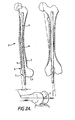
- An alignment rod 6, which may be of different length to accommodate different sizes of femur, for example 300mm, 380mm, 460mm, is inserted through a large access hole 7 between the femoral condyle 5 and is pushed upwards into the femur to take up the position shown in Figure 2a.
- the femoral alignment rod 6 makes contact with the posterior bone cortex 8 of the femur, which pushes the rod 6 forwards, and the rod is constrained anteriorly by the anterior bone cortex 9.
- the rod 6 takes up a position which is offset by a distance X from the anterior surface of the femur in the region indicated by A, where X is typically 13.55mm, but may vary between l3mm and l5mm, and Lies at an angle of approximately 7° to the vertical axis.
- alignment rod introducer 10 which includes a handle 11 and a bore 12 for accommodating the alignment rod.
- Each alignment rod 6 includes a slot 6a near its end.
- the alignment rod introducer 10 includes a pivotal member 13 which is pivotted about point 13a to produce a rocking movement. At the end of member 13 is a projection 15 which may be accommodated in the slot 6a of the alignment rod.
- a slidable sleeve 14 which slides readily along alignment rod introducer 10.
- a clearance hole 7 is first drilled into the intercondylar notch of the femur so that the alignment rod 6 may be aligned in the correct position within the femoral medulla 3. This then defines the angle of approximately 7° to the vertical axis.
- the alignment rod introducer 10 is then removed from the end of the alignment rod 6.
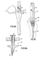
- an angle adaptor 16 includes a bar 17 at an angle of approximately 83° to a tubular section 18 through which passes a bore 19 for accommodating the alignment rod 6.
- the angle adaptor 16 is inserted over the alignment rod 6 so that the bar 17 is parallel to the posterior condyles, as judged by the surgeon.
- the bar 17 includes on its inner surface two spikes 20 which key into the bone of the femur to fix the angle adaptor into the correct position.
- a first femoral saw guide 21 includes a handle 22 and a perpendicular block 23.
- the block 23 includes a groove 24 for accommodating the bar 17 of the angle adaptor 16, and a slot 25 for accommodating the alignment rod 6.
- Upper saw guide slots 26 and lower saw guide slots 27 are parallel to the handle 22. The saw guide 21 is inserted over the angle adaptor 16 so that the groove 24 engages with the bar 17 of the angle adaptor 16, and the anterior resection of the femur is effected by inserting a saw through the upper saw guide slots 16.
- the posterior resection of the femur is carried out by inserting a saw in the lower saw guide slots 27 and in each case the cutting of the whole width of the femur is facilitated by sliding the saw guide 21 along the bar 17, whilst the alignment rod 6 slides along the slot 25.
- the anterior resection Whilst the anterior resection is always carried out flush to the anterior surface of the femur, due to the constant distance of the alignment rod from the anterior cortex of the femur, the posterior resection depends on the size and type of the femoral component to be used. Therefore, although the upper slots 26 are always in the same position relative to the groove 24, there may be included a number of lower saw guide slots 27, the pair chosen to act as a saw guide depending on the type and size of the femoral component to be used.
- a second femoral saw guide 28 includes a handle 29 and a perpendicular block 30 which is in the form of a U-shaped channel.
- the width of the channel is the same width as the width between the two pairs of slots 26 and 27 on the first saw guide 21.
- the second saw guide 28 may fit snuggly over the resected region of the femur.
- a slot 31 is used to accommodate the alignment rod, and slots 32 are perpendicular to the longitudinal axis of the handle 29 to allow the inferior resection of the femur, as shown in Figure 6a.
- the saw guide 28 may be slid medially or laterally on the femur, since the alignment rod 6 slides along in the slot 31.
- a femoral template 33 such as that shown in Figure 7 is used to check that the correct shape has been cut on the femur.
- a hole 34 is drilled at the proximal end of the tibia 1, and a tibial alignment rod 35, identical to the femoral alignment rod 6, is introduced into the medulla of the tibia using alignment rod introducer 10.
- the alignment rod introducer 10 is removed to leave the alignment rod 35 in position.
- a horizontal plateau, known as the tibial plateau is then cut on the proximal end of the tibia, and this is achieved by using the tibial saw guide 36 shown in Figure 9.
- the saw guide 36 includes handle 37 including a bore 38 for accommodating the alignment rod 6, and a fixed block 39 attached to the end of the handle. Slidably attached to fixed portion 39 is an extension piece 40 including two slots 41. The saw guide can then be used to cut a complete tibial plateau in the proximal end of the tibia, since the extension piece 40 can slide in and out of engagement with any obstruction on the outside of the tibia, as shown in Figure 9a.
- a reamer 42 is used to cut a surface of revolution in the top of the tibial plateau.
- Each reamer 42 includes a mandral 42a with an eccentric bore 43 to accommodate the alignment rod 35 so as to produce a surface of revolution centred about the correct central axis.
- Each reamer has cutting edges 42 which cut into the tibia as the reamer is rotated.
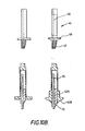
- a broach 45 includes an eccentric bore 46 for accommodating the alignment rod 35, and a rasp section 47 for cutting the correct shaped axial socket in the tibial medulla.
- a suitably shaped collar section 48 prevents broaching to an excessive depth.
- the eccentricity of the bore 46 ensures that the axial socket is cut into the tibia about the correct central axis, which is horizontally displaced from the axis of the tibial alignment rod.
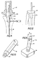
- a tibial component 50 which includes an eccentric bore 51 for accommodating the alignment rod 35 is tapped home into the socket by means of a tibial impactor 52.
- the tibial impactor 52 includes an alignment rod bore 53 and a reduced diameter head 54 for engaging the articulating surface of the tibial component 50. This procedure is shown in Figure 14.
- the femoral component may then be introduced onto the femur using a femoral impactor 55.
- the head 56 of the impactor is at an angle of approximately 83° to the bore 57 within the handle 58 of the impactor.
- the femoral component includes an intercondylar gap which can accommodate the alignment rod as shown in Figure 16, but in the case where a femoral component is used which does not have such a slot, preferably a hole is provided in the articulating surface to allow the alignment rod 6 to pass through.
- the impactor 55 is slid over the alignment rod 6, and used to push the femoral prosthesis into place. In the case of a three part knee, the third component of a knee prosthesis is then slipped into position between the tibial and femoral components.
- alignment rods 6 and 35 may be of any suitable metal, they are typically made of steel, and have a diameter of typically 6mm.
- the instruments of the present invention whilst allowing the appropriate bone rresections to be carried out in the correct planes, also provides a means for locating the femoral and tibial components into their respective correct positions, and this is particularly important when when bone cement is used, since in this case more bone is resected than is strictly necessary in order to leave a space for the bone cement, and without the alignment provided by the instruments of the present invention, accurate location of the components could not be achieved.
Abstract
Description
- The present invention relates to instruments for use in the implanation of a knee prosthesis.
- When fully extended, a vertical axis drawn through the centre of the femoral head passes through the centre of the knee joint and along the tibial medulla. This vertical axis is referred to as the mechanical axis, and it is along this axis that load is transmitted.
- However, the femoral medulla lies at an angle of 6° to 8°, typically 7°, to this mechanical axis.
- It is important therefore when implanting a knee prosthesis to maintain a horizontally aligned bearing surface between the tibial and femoral components so that load is transmitted as in a natural joint.
- Currently known methods of ensuring the correct positioning of the femoral and tibial components on the femur and tibia respectively involve the use of an external guide rod which is fixed to the outside of the leg prior to surgery, using the vertical axis passing through the centre of the hip as a visual guide. With such a method it is extremely difficult to cut bone sufficiently accurately from the natural joint so that the prosthetic component is a precise fit and, for instance, is flush with a natural bone at its edges.
- According to the present invention there is provided a set of instruments for use in the surgical implantation of a knee prosthesis, including a femoral alignment rod one end of which is for insertion into the medulla of a femur through an access hole located between the femoral condyles, said end being sufficiently blunt and said rod being of sufficient flexibility that the rod will not penetrate the bone of the femur but rather will bend to travel within the medulla, said rod being however of sufficient resilience to maintain its linearity within the femur as far as possible, said rod being of sufficient length to extend at least beyond the lesser trochanter with the other end of said rod protruding exteriorly from between the femoral condyles, the set of instruments further including an angle adaptor having an elongate body portion and also having means to allow the adaptor to be slid over and rotated about the protruding alignment rod with the longitudinal axis of the body portion of the adaptor forming an acute angle with the longitudinal axis of the alignment rod, said angle adaptor also having means rigidly to fix said angle adaptor to the femur.
- The access hole should be of greater diameter than the diameter of the alignment rod such that when the alignment rod is fully inserted, it does not contact bone about the access hole. Accordingly the rod takes up a position dictated by points of contact within the medulla between the rod and the inner walls of the bone defining the medulla. It has been surprisingly found that with a rod which is as described above and which extends beyond the lesser trochanter and in which no constraint is placed on its position at or near the point of entry into the bone, the rod will adopt a position which is a constant distance from the anterior cortex of the femur at a point just proximal to the patella facets of the femoral condyles. This distance is typically 13.55mm, and varies only in the
range 13 to l5mm. This is the case regardless of the size of the patient and the condition of the patient's bones. This discovery is utilised in this invention to enable a cutting guide to be located about the protruding rod so that precisely the correct amount of bone can be removed from, in particular, the front of the joint in what is termed anterior resection so that the resected surface is absolutely flush with the anterior cortex of the femur, and so, when fitted, the femoral component follows the profile of a natural joint. - Referring again to the rod itself, the end inserted into the bone is, as mentioned above, blunt (for instance a flat end with a chamferred peripheral edge in order to provide no sharp edges) and as it is pushed into the medulla it tries to take the easiest possible path down the middle. The bone is however curved and the rod hits harder bone and deflects. The rod is pushed in as far as it will reasonably go and the hardness of the bone wall maintains the bend in the rod. In practice the set of instruments may include a plurality of such rods of varying lengths, the surgeon chosing a rod of appropriate length for a particular patient so that, when inserted fully into the bone an appropriate length of rod protrudes as mentioned above. Typically the rod will protrude an amount of about 4 inches although the actual length of protrusion is one of convenience to the surgeon rather than essential to the invention.
- Typically the rod diameter is from 5 to 7mm, preferably from 5.5 to 6.5mm and in one embodiment is about 6mm diameter. The rod may be made of stainless steel or of some other appropriate material, such as another metal or a reinforced plastics material.
- When located in position within the bone the rod is bent laterally to follow the curve of the bone. However, from the front the rod is straight and defines an axis of the femur.
- When in position the rod extends linearily, as mentioned above, at an angle of approximately 7° to the mechanical axis extending from the hip joint along the axis of the tibia. The purpose of the angle adaptor is to compensate for this approximately 7° deviation from the mechanical axis.
- Preferably the longitudinal axis of the body portion of the angle adaptor forms an angle of between 82° and 84° to the longitudinal axis of the femoral alignment rod.
- Thus, the angle adaptor, when slid over the protruding femoral alignment rod defines a plane which is at an angle of approximately 83° to the axis of the alignment rod, and so which is perpendicular to the mechanical axis.
- The plane defined by the angle adaptor forms a basis for the preparation of the femur to receive the femoral component of the knee prosthesis and ensures that the femoral component, when fitted, presents an articulating surface which is perpendicular to the mechanical axis.
- Preferably the femoral alignment rod is of a sufficient length to extend beyond the lesser trochanter of the femur whilst still protruding from the femoral condyles.
- In order to aid insertion of the femoral rod into the femoral medulla, an alignment rod introducer is preferably included in the set of instruments. This has a handle portion and means to releasably grip an end of the alignment rod so that the introducer can be used to insert and rotate the alignment rod within the medulla.
- Preferably the set of instruments includes a first femoral saw guide for resecting anterior and posterior portions of the distal end of the femur, the saw guide including means to accommodate the body portion of the angle adaptor, a central slot for slidably accommodating the protruding femoral alignment rod, a pair of upper slots for guiding a saw to resect an anterior portion of the femur, and one or more pairs of lower slots for guiding a saw to resect a posterior portion of the femur.
- Preferably, a number of different pairs of lower slots are provided, the surgeon choosing the correct pair of slots to suit the size of the particular femoral component to be implanted.
- Thus, in use, the first femoral saw guide is placed over the end of the femoral alignment rod and engages the body portion of the angle adaptor. When the first femoral saw guide is in place, a saw is passed through the upper slots to resect the anterior portion of the femur, and through the lower slots to resect the posterior portion of the femur. The engagement of the saw guide over the angle adaptor ensures that the resections are carried out in the correct plane.
- Preferably the set of instruments includes a second femoral saw guide for resecting an inferior portion of the distal end of the femur, the saw guide including means to accommodate the body portion of the angle adaptor, a central slot for slidably accommodating the protruding femoral alignment rod, and upper and lower pairs of slots for guiding a saw to resect an inferior portion of the femur.
- Thus, in use, the second saw guide is placed over the femoral alignment rod and the saw guide engages the body portion of the angle adaptor. A saw is then placed through the upper and lower pairs of slots to resect the inferior portion of the femur. Again, the engagement of the guide with the angle adaptor ensures that the resection is carried out in this correct plane.
- Having carried out the resection, a femoral template may be placed over the resected portion to ensure that the correct degree of resection has been carried out.
- Preferably the set of instruments includes a tibial alignment rod for insertion into the medulla of the tibia through an access hole located in the proximal end of the tibia, the rod being of sufficient length so as, when fully inserted, to protrude from said end, and one or more cutting tools for cutting a recess into the tibia, said tool or tools being adapted to rotate about an axis which is parallel to but horizontally displaced from the longitudinal axis of the tibial alignment rod.
- Preferably said tool or tools includes a mandrel having an eccentric bore for engaging the tibial alignment rod and having an outer cylindrical surface with a longitudinal axis parallel to but horizontally displaced from the axis of the tibial alignment rod, said tool or tools being arranged for rotation about the cylindrical surface of said mandrel.
- Preferably said tool or tools comprise a reamer for cutting out a surface of revolution in the proximal end of the tibia, and a broach for cutting an axial socket in the tibia.
- Thus, the present invention gives the advantage that conical recesses for accommodating a tibial component may be formed in the tibia, the recesses being centred about an access which is located posteriorly of the alignment rod, which is necessary so that the axis of rotation of the knee prosthesis, when implanted, is located behind the natural axis of the tibial medulla, ie. behind the mechanical axis.
- Preferably the tibial alignment rod is of a sufficient length so as to extend close to the ankle joint whilst still protruding from the proximal end of the tibia.
- Preferably the set of instruments includes a tibial saw guide for cutting a tibial plateau on the proximal end of the tibia, the saw guide comprising means to slidably and rotatably accommodate the protruding tibial alignment rod, and a pair of slots to guide a saw to cut a complete tibial plateau on the proximal end of the tibia.
- Preferably the slots in the tibial saw guide are adjustable in position relative to the tibial alignment rod so as to allow the guide to be rotated about the whole of the tibia.
- Thus, having inserted the tibial alignment rod, the tibial saw guide is used to cut a tibial plateau into the end of the tibia, by inserting the saw guide over the end of the tibial alignment rod and inserting a saw within the slots in the saw guide and rotating the saw guide around the whole of the tibia.
- Having cut a tibial plateau, a reamer is used to cut a surface of revolution on the tibial plateau, to accommodate the shape of the articulating portion of the tibial component.
- Preferably the set of instruments includes a constraining member which is in the form of a bifurcated pin for insertion through the tibia to engage a portion of the mandrel of the reamer to prevent excess reaming of the tibia.
- Then a broach is tapped into the top of the tibia, either by means of a separate hammer or by means of an integral hammer, and used to cut an axial socket for the stem of the tibial component, the broach preferably including a stop collar to limit the depth of the axial socket cut.
- Preferably the instruments are used with a tibial component of a knee prosthesis which has an eccentric bore therein to accommodate the tibial alignment rod.
- Thus having cut the correct axial socket for the tibial component, the tibial component is pushed into the axial socket over the end of the tibial alignment rod.
- Preferably the set of instruments includes a tibial impactor for pushing the tibial component of a knee prosthesis home within the axial socket, the impactor having an eccentric bore therein to accommodate the tibial alignment rod.
- Preferably the set of instruments includes a femoral pusher having means to push a femoral component of a knee prosthesis home onto the resected portion of the femur, said pushing means being inclined at an angle of between 82° to 84° to the longitudinal axis of the femoral alignment rod.
- Preferably the instruments are used with a femoral component of a knee prosthesis having an opening in its bearing surface through which the femoral alignment rod may pass.
- Thus, a single set of instruments is used to prepare the femur and tibia and also to insert the femoral and tibial components in their correct positions on the femur and tibia.
- Embodiments of the present invention will now be described by way of example only with reference to the accompanying drawings in which:-
- Figure 1 is an anterior view of the femur and tibia;
- Figure 2 is an enlargement of Figure 1 showing the inclination of the axis of the femoral medulla to the mechanical axis;
- Figure 2a shows both medio-lateral and anterior- posterior cross sections through the femur showing the position of the alignment rod;
- Figure 3 is a perspective view of an alignment rod introducer being used to insert a femoral alignment rod;
- Figure 4 shows the angle adaptor inserted over the femoral alignment rod;
- Figure 4a is another view of the angle adaptor shown in Figure 4, showing the mechanism for fixing the angle adpator;
- Figure 5 is a perspective view of a first femoral saw guide;
- Figure 5a shows the femoral saw guide shown in Figure 5 being used to resect anterior and posterior portions of the femur;
- Figure 6 is a perspective view of a second femoral saw guide;
- Figure 6a shows the second femoral saw guide shown in Figure 6 being used to resect an inferior portion of the femur;
- Figure 7 shows a femoral template;
- Figure 8 shows a tibial alignment rod inserted within the tibia;
- Figure 9 is a perspective view of a tibial saw guide;
- Figure 9a shows the tibial saw guide shown in Figure 9 being used to cut a tibial plateau on the tibia;
- Figure 10 shows a perspective view of a broach being used to cut an axial socket in the tibia;
- Figure 10a shows an alternative embodiment of a broach having an integral slide hammer;
- Figure 10b shows examples of broaches and reamers;
- Figure 11 shows a reamer for cutting a surface of revolution in the tibia, including a constraining pin;
- Figure 12 shows a tibial component of a knee prosthesis inserted in place over the tibial alignment rod;
- Figure 13 is a perspective view of a tibial impactor;
- Figure 14 shows the tibial impactor being used to push the tibial component home into the axial socket of the tibia;
- Figure 15 is a perspective view of a femoral pusher; and,
- Figure 16 shows the femoral pusher being used to push the femoral component onto the resected end of the femur.
- The
tibia 1 andfemur 2 both include an elongate bore known as a medulla 3. The medulla 3 of thetibia 1 lies in a vertical axis, which, if extended, passes through the centre of the knee and through the head of the femur. Thefemur 2 has its medulla at an angle of approximately 7° to the vertical axis. However, the femoral condyles 5 are approximately parallel to a horizontal plane. Analignment rod 6, which may be of different length to accommodate different sizes of femur, for example 300mm, 380mm, 460mm, is inserted through a large access hole 7 between the femoral condyle 5 and is pushed upwards into the femur to take up the position shown in Figure 2a. Thefemoral alignment rod 6 makes contact with theposterior bone cortex 8 of the femur, which pushes therod 6 forwards, and the rod is constrained anteriorly by the anterior bone cortex 9. This means that therod 6 takes up a position which is offset by a distance X from the anterior surface of the femur in the region indicated by A, where X is typically 13.55mm, but may vary between l3mm and l5mm, and Lies at an angle of approximately 7° to the vertical axis. - In order to easily move
alignment rod 6 it is important to have analignment rod introducer 10 which includes ahandle 11 and abore 12 for accommodating the alignment rod. Eachalignment rod 6 includes a slot 6a near its end. Thealignment rod introducer 10 includes apivotal member 13 which is pivotted about point 13a to produce a rocking movement. At the end ofmember 13 is aprojection 15 which may be accommodated in the slot 6a of the alignment rod. On the outer surface ofalignment rod introducer 10 is aslidable sleeve 14 which slides readily alongalignment rod introducer 10. The sliding ofsleeve 14 bears against the rockingmember 13 to cause theprojection 15 either to be brought out of contact with the alignment rod or into contact with the alignment rod in slot 6a to fix thealignment rod introducer 10 to the end of thealignment rod 6. Thus, with the held ofhandle 11, the alignment rod may be rotated, pulled or pushed into position. - In order to fit an alignment rod into the femur, a clearance hole 7 is first drilled into the intercondylar notch of the femur so that the
alignment rod 6 may be aligned in the correct position within the femoral medulla 3. This then defines the angle of approximately 7° to the vertical axis. Thealignment rod introducer 10 is then removed from the end of thealignment rod 6. - Referring now to Figures 4 and 4a, an
angle adaptor 16 includes abar 17 at an angle of approximately 83° to atubular section 18 through which passes a bore 19 for accommodating thealignment rod 6. Theangle adaptor 16 is inserted over thealignment rod 6 so that thebar 17 is parallel to the posterior condyles, as judged by the surgeon. Thebar 17 includes on its inner surface twospikes 20 which key into the bone of the femur to fix the angle adaptor into the correct position. - Since the horizontal plane has now been located, saw guides may now be used to cut away the require shape for accommodating a femoral component of a knee prosthesis. A first femoral saw
guide 21 includes ahandle 22 and aperpendicular block 23. Theblock 23 includes agroove 24 for accommodating thebar 17 of theangle adaptor 16, and aslot 25 for accommodating thealignment rod 6. Upper sawguide slots 26 and lowersaw guide slots 27 are parallel to thehandle 22. Thesaw guide 21 is inserted over theangle adaptor 16 so that thegroove 24 engages with thebar 17 of theangle adaptor 16, and the anterior resection of the femur is effected by inserting a saw through the uppersaw guide slots 16. In a similar way, the posterior resection of the femur is carried out by inserting a saw in the lowersaw guide slots 27 and in each case the cutting of the whole width of the femur is facilitated by sliding thesaw guide 21 along thebar 17, whilst thealignment rod 6 slides along theslot 25. - Whilst the anterior resection is always carried out flush to the anterior surface of the femur, due to the constant distance of the alignment rod from the anterior cortex of the femur, the posterior resection depends on the size and type of the femoral component to be used. Therefore, although the
upper slots 26 are always in the same position relative to thegroove 24, there may be included a number of lowersaw guide slots 27, the pair chosen to act as a saw guide depending on the type and size of the femoral component to be used. - Referring to Figure 6, a second femoral saw
guide 28 includes ahandle 29 and aperpendicular block 30 which is in the form of a U-shaped channel. The width of the channel is the same width as the width between the two pairs ofslots first saw guide 21. Thus thesecond saw guide 28 may fit snuggly over the resected region of the femur. Aslot 31 is used to accommodate the alignment rod, and slots 32 are perpendicular to the longitudinal axis of thehandle 29 to allow the inferior resection of the femur, as shown in Figure 6a. Again thesaw guide 28 may be slid medially or laterally on the femur, since thealignment rod 6 slides along in theslot 31. Afemoral template 33 such as that shown in Figure 7 is used to check that the correct shape has been cut on the femur. - Referring now to Figure 8, a
hole 34 is drilled at the proximal end of thetibia 1, and atibial alignment rod 35, identical to thefemoral alignment rod 6, is introduced into the medulla of the tibia usingalignment rod introducer 10. When thealignment rod 35 is in place within the tibia, thealignment rod introducer 10 is removed to leave thealignment rod 35 in position. - A horizontal plateau, known as the tibial plateau is then cut on the proximal end of the tibia, and this is achieved by using the tibial saw
guide 36 shown in Figure 9. Thesaw guide 36 includeshandle 37 including abore 38 for accommodating thealignment rod 6, and a fixedblock 39 attached to the end of the handle. Slidably attached to fixedportion 39 is anextension piece 40 including twoslots 41. The saw guide can then be used to cut a complete tibial plateau in the proximal end of the tibia, since theextension piece 40 can slide in and out of engagement with any obstruction on the outside of the tibia, as shown in Figure 9a. - Referring now to Figure 11, a
reamer 42 is used to cut a surface of revolution in the top of the tibial plateau. Eachreamer 42 includes a mandral 42a with aneccentric bore 43 to accommodate thealignment rod 35 so as to produce a surface of revolution centred about the correct central axis. Each reamer has cuttingedges 42 which cut into the tibia as the reamer is rotated. - Referring now to Figures 10, 10a and 10b, a
broach 45 includes aneccentric bore 46 for accommodating thealignment rod 35, and arasp section 47 for cutting the correct shaped axial socket in the tibial medulla. A suitably shapedcollar section 48 prevents broaching to an excessive depth. - In the embodiments shown in Figure 10, a separate hammer is used to impact the broach into .the tibia, but in Figure 10a an alternative embodiment is shown in which there is included an
integral side hammer 49 to ensure that the force is applied in the correct place on the tibia. - The eccentricity of the
bore 46 ensures that the axial socket is cut into the tibia about the correct central axis, which is horizontally displaced from the axis of the tibial alignment rod. - Once the axial socket has been cut, a
tibial component 50 which includes aneccentric bore 51 for accommodating thealignment rod 35 is tapped home into the socket by means of atibial impactor 52. Thetibial impactor 52 includes an alignment rod bore 53 and a reduceddiameter head 54 for engaging the articulating surface of thetibial component 50. This procedure is shown in Figure 14. - The femoral component may then be introduced onto the femur using a
femoral impactor 55. Thehead 56 of the impactor is at an angle of approximately 83° to thebore 57 within thehandle 58 of the impactor. The femoral component includes an intercondylar gap which can accommodate the alignment rod as shown in Figure 16, but in the case where a femoral component is used which does not have such a slot, preferably a hole is provided in the articulating surface to allow thealignment rod 6 to pass through. The impactor 55 is slid over thealignment rod 6, and used to push the femoral prosthesis into place. In the case of a three part knee, the third component of a knee prosthesis is then slipped into position between the tibial and femoral components. - Only at this point, when both components of the prosthesis have been inserted, are the
alignment rods - Whilst the
alignment rods - It should be appreciated that the instruments of the present invention, whilst allowing the appropriate bone rresections to be carried out in the correct planes, also provides a means for locating the femoral and tibial components into their respective correct positions, and this is particularly important when when bone cement is used, since in this case more bone is resected than is strictly necessary in order to leave a space for the bone cement, and without the alignment provided by the instruments of the present invention, accurate location of the components could not be achieved.
Claims (17)
Priority Applications (1)
| Application Number | Priority Date | Filing Date | Title |
|---|---|---|---|
| AT86300525T ATE87814T1 (en) | 1985-01-25 | 1986-01-27 | SURGICAL INSTRUMENTS. |
Applications Claiming Priority (2)
| Application Number | Priority Date | Filing Date | Title |
|---|---|---|---|
| GB858501907A GB8501907D0 (en) | 1985-01-25 | 1985-01-25 | Surgical instruments |
| GB8501907 | 1985-01-25 |
Publications (2)
| Publication Number | Publication Date |
|---|---|
| EP0194014A1 true EP0194014A1 (en) | 1986-09-10 |
| EP0194014B1 EP0194014B1 (en) | 1993-04-07 |
Family
ID=10573394
Family Applications (1)
| Application Number | Title | Priority Date | Filing Date |
|---|---|---|---|
| EP86300525A Expired - Lifetime EP0194014B1 (en) | 1985-01-25 | 1986-01-27 | Surgical instruments |
Country Status (6)
| Country | Link |
|---|---|
| US (1) | US4791919A (en) |
| EP (1) | EP0194014B1 (en) |
| JP (1) | JPH0624548B2 (en) |
| AT (1) | ATE87814T1 (en) |
| DE (1) | DE3688207T2 (en) |
| GB (1) | GB8501907D0 (en) |
Cited By (10)
| Publication number | Priority date | Publication date | Assignee | Title |
|---|---|---|---|---|
| WO1988004912A2 (en) * | 1986-12-24 | 1988-07-14 | Orthomet, Inc. | Bone cutting guide and methods for using same |
| EP0381893A1 (en) * | 1988-12-22 | 1990-08-16 | John M. Dr. Agee | Instrumentation for implanting prosthetic devices |
| EP0384562A1 (en) * | 1989-01-30 | 1990-08-29 | Wright Medical Technology, Inc. | Tibial surface shaping guide for knee implants |
| EP0425472A1 (en) * | 1989-10-25 | 1991-05-02 | Hans Georg Dr. Ender | Bone nail and tool therefor |
| EP0441256A1 (en) * | 1990-02-08 | 1991-08-14 | Gebrüder Martin GmbH & Co. KG | Tool arrangement for bone nails |
| EP0528145A1 (en) * | 1991-07-19 | 1993-02-24 | Pennig, Dietmar, Dr. med. | Introduction aid for straight and solid intramedullary anchorage nail |
| US5417693A (en) * | 1992-06-17 | 1995-05-23 | Minnesota Mining And Manufacturing Company | Instrumentation for preparing the femur for an artificial knee implant and for positioning the femoral component of the implant |
| US5722978A (en) * | 1996-03-13 | 1998-03-03 | Jenkins, Jr.; Joseph Robert | Osteotomy system |
| EP2526876A3 (en) * | 2006-10-11 | 2013-10-09 | Ignace Ghijselings | Device for installing femoral prosthetic knee joint |
| IT202000005947A1 (en) * | 2020-03-19 | 2021-09-19 | Limacorporate Spa | GUIDED MILLING DEVICE FOR PROSTHETIC SURGERY |
Families Citing this family (46)
| Publication number | Priority date | Publication date | Assignee | Title |
|---|---|---|---|---|
| US4795473A (en) * | 1987-01-09 | 1989-01-03 | Grimes James B | Extramedullary femoral head-neck prosthesis and method of implanting same |
| US4935023A (en) * | 1989-01-09 | 1990-06-19 | Dow Corning Wright | Femoral surface shaping guide for knee implants |
| US4927422A (en) * | 1989-08-31 | 1990-05-22 | Boehringer Mannheim Corporation | Elbow arthroplasty instrumentation and surgical procedure |
| US5171244A (en) * | 1990-01-08 | 1992-12-15 | Caspari Richard B | Methods and apparatus for arthroscopic prosthetic knee replacement |
| US5002543A (en) * | 1990-04-09 | 1991-03-26 | Bradshaw Anthony J | Steerable intramedullary fracture reduction device |
| US5092869A (en) * | 1991-03-01 | 1992-03-03 | Biomet, Inc. | Oscillating surgical saw guide pins and instrumentation system |
| US5129909A (en) * | 1991-03-13 | 1992-07-14 | Sutherland Charles J | Apparatus and method for making precise bone cuts in total knee replacement |
| US5275603A (en) * | 1992-02-20 | 1994-01-04 | Wright Medical Technology, Inc. | Rotationally and angularly adjustable tibial cutting guide and method of use |
| US5462549A (en) * | 1992-05-01 | 1995-10-31 | Biomet, Inc. | Femoral sizing apparatus |
| CA2098081A1 (en) * | 1992-08-13 | 1994-02-14 | Terry L. Dietz | Alignment guide and method |
| US5433720A (en) * | 1992-09-22 | 1995-07-18 | Orthofix S.R.L. | Centering means for holes of intramedullary nails |
| CA2149916C (en) * | 1992-11-20 | 2004-10-26 | Dennis W. Burke | Prosthetic implant collar |
| US5951606A (en) | 1992-11-20 | 1999-09-14 | Burke; Dennis W. | Centering device for femoral implant and method and apparatus for implementation thereof |
| US5702485A (en) * | 1992-11-20 | 1997-12-30 | Burke; Dennis W. | Collared prosthetic device with centering fins |
| US5431660A (en) * | 1993-11-30 | 1995-07-11 | Burke; Dennis W. | Spring loaded screw and driver/extractor therefor |
| US5616146A (en) * | 1994-05-16 | 1997-04-01 | Murray; William M. | Method and apparatus for machining bone to fit an orthopedic surgical implant |
| US5484446A (en) * | 1994-06-27 | 1996-01-16 | Zimmer, Inc. | Alignment guide for use in orthopaedic surgery |
| US5693048A (en) * | 1995-03-13 | 1997-12-02 | Zimmer, Inc. | Intramedullary rod guide member lock |
| US5613970A (en) * | 1995-07-06 | 1997-03-25 | Zimmer, Inc. | Orthopaedic instrumentation assembly having an offset bushing |
| US5634927A (en) * | 1995-07-06 | 1997-06-03 | Zimmer, Inc. | Sizing plate and drill guide assembly for orthopaedic knee instrumentation |
| US6171342B1 (en) * | 1996-07-23 | 2001-01-09 | Depuy Orthopaedics, Inc. | Medical fastening system |
| US5830216A (en) * | 1996-10-30 | 1998-11-03 | Bristol-Myers Squibb Company | Apparatus and method for knee implantation |
| GB9705172D0 (en) * | 1997-03-13 | 1997-04-30 | Zimmer Limited | Evaluating the fit of an orthopaedic implant |
| US6344043B1 (en) | 1997-11-18 | 2002-02-05 | Michael J. Pappas | Anterior-posterior femoral resection guide with set of detachable collets |
| US6440138B1 (en) | 1998-04-06 | 2002-08-27 | Kyphon Inc. | Structures and methods for creating cavities in interior body regions |
| US6527807B1 (en) * | 1998-09-09 | 2003-03-04 | Johnson & Johnson Professional, Inc. | Femoral stem attachment for a modular knee prosthesis |
| US7635390B1 (en) | 2000-01-14 | 2009-12-22 | Marctec, Llc | Joint replacement component having a modular articulating surface |
| EP1480582B1 (en) * | 2002-02-14 | 2012-07-18 | Biomet Spain Orthopaedics S.L. | Patello-femoral joint replacement |
| WO2004037119A2 (en) | 2002-10-23 | 2004-05-06 | Mako Surgical Corp. | Modular femoral component for a total knee joint replacement for minimally invasive implantation |
| US20040243134A1 (en) * | 2003-05-30 | 2004-12-02 | Walker Peter Stanley | Bone shaping device for knee replacement |
| US7632284B2 (en) | 2004-07-06 | 2009-12-15 | Tyco Healthcare Group Lp | Instrument kit and method for performing meniscal repair |
| US7963968B2 (en) | 2004-12-21 | 2011-06-21 | Smith & Nephew, Inc. | Distal femoral trial with removable cutting guide |
| WO2007062132A2 (en) * | 2005-11-23 | 2007-05-31 | Trinity Orthopedics | Percutaneous transpedicular access, fusion, discectomy, and stabilization system and method |
| US20080287958A1 (en) * | 2007-05-14 | 2008-11-20 | Howmedica Osteonics Corp. | Flexible intramedullary rod |
| US8206389B2 (en) * | 2007-08-31 | 2012-06-26 | Huebner Randall J | Rod-based system for bone fixation |
| JP2011092405A (en) * | 2009-10-29 | 2011-05-12 | Lexi:Kk | Program for preoperative plan of artificial knee joint replacement operation |
| EP2468216B1 (en) * | 2010-12-23 | 2014-05-14 | Baumgart, Rainer, Dipl.-Ing. Dr. med. | Implantable prosthesis for replacing human hip or knee joints and the adjoining bone sections |
| JP5859810B2 (en) * | 2011-10-31 | 2016-02-16 | 京セラメディカル株式会社 | Surgical instrument for hip replacement |
| US9232950B2 (en) * | 2013-03-15 | 2016-01-12 | Depuy (Ireland) | Femoral orthopaedic surgical instruments for setting offset |
| US9636122B2 (en) | 2013-03-15 | 2017-05-02 | Depuy Ireland Unlimited Company | Femoral orthopaedic instrument assembly for setting offset |
| JP6151570B2 (en) * | 2013-05-29 | 2017-06-21 | 株式会社大野興業 | Surgical jig, confirmation jig, and method of manufacturing these jigs |
| EP4154827A1 (en) * | 2015-05-13 | 2023-03-29 | Smith & Nephew, Inc. | System for orthopedic implantation preparation |
| WO2016183459A2 (en) * | 2015-05-13 | 2016-11-17 | Smith & Nephew, Inc. | System for orthopedic implantation preparation |
| US10716682B2 (en) | 2017-07-19 | 2020-07-21 | Acumed Llc | Orthopedic alignment guide |
| US11123085B2 (en) | 2018-04-11 | 2021-09-21 | Howmedica Osteonics Corp. | Cutting tool positioned by flexible rod for revision surgery |
| JP6620202B2 (en) * | 2018-09-25 | 2019-12-11 | 京セラ株式会社 | Pin holder and surgical tool for IBG procedure |
Citations (4)
| Publication number | Priority date | Publication date | Assignee | Title |
|---|---|---|---|---|
| US4457307A (en) * | 1982-08-20 | 1984-07-03 | Stillwell William T | Bone cutting device for total knee replacement |
| EP0121142A1 (en) * | 1983-03-09 | 1984-10-10 | Dow Corning Corporation | Apparatus for shaping a distal femoral surface |
| US4487203A (en) * | 1981-11-03 | 1984-12-11 | Androphy Gary W | Triplanar knee resection method |
| US4524766A (en) * | 1982-01-07 | 1985-06-25 | Petersen Thomas D | Surgical knee alignment method and system |
Family Cites Families (16)
| Publication number | Priority date | Publication date | Assignee | Title |
|---|---|---|---|---|
| FR1166261A (en) * | 1957-02-12 | 1958-11-04 | Fr De Fournitures Chirurgicale | Required for the treatment of bone fractures |
| FR2076838A5 (en) * | 1970-01-30 | 1971-10-15 | Lyon Ass Arts Et Metiers | |
| US3763855A (en) * | 1972-03-15 | 1973-10-09 | Atee R Mc | Device for fixation of bone fractures |
| US4135507A (en) * | 1977-05-20 | 1979-01-23 | Harris Leslie J | Condylocephalic nail for fixation of pertrochanteric fractures |
| GB1601576A (en) * | 1977-06-01 | 1981-10-28 | Howmedica | Elbow prosthesis |
| DE2728427C2 (en) * | 1977-06-24 | 1986-03-06 | S + G Implants GmbH, 2400 Lübeck | Knee joint endoprosthesis |
| US4169470A (en) * | 1977-10-19 | 1979-10-02 | Ender Hans G | Surgical nail for use in setting bone fractures, and tool for emplacing same |
| JPS5526987A (en) * | 1978-05-31 | 1980-02-26 | Wadsworth Thomas G | Elbow replacement prosthetic dentistry device |
| EP0010527A1 (en) * | 1978-10-06 | 1980-04-30 | L.I.M.A. Lualdi Industrie MeccanicheAnduis Srl. | Prosthesis for limbs |
| SU762877A1 (en) * | 1978-10-27 | 1980-09-15 | Tsnii Travmatologii Ortopedii | Device for inserting fixing member for osteosynthesis of the femural bone |
| DE3142730A1 (en) * | 1981-04-01 | 1982-10-21 | Curt Dipl.-Ing. 1000 Berlin Kranz | "JOINT PROSTHESIS" |
| US4567885A (en) * | 1981-11-03 | 1986-02-04 | Androphy Gary W | Triplanar knee resection system |
| US4457301A (en) * | 1982-06-18 | 1984-07-03 | Howmedica Inc. | Intramedullary fixation device |
| US4467801A (en) * | 1983-03-09 | 1984-08-28 | Wright Manufacturing Company | Method and apparatus for shaping a proximal tibial surface |
| US4621630A (en) * | 1983-04-15 | 1986-11-11 | Pfizer Hospital Products Group, Inc. | Guide for femoral neck osteotomy |
| US4627425A (en) * | 1983-09-28 | 1986-12-09 | Reese H William | Osteotomy appliances and method |
-
1985
- 1985-01-25 GB GB858501907A patent/GB8501907D0/en active Pending
-
1986
- 1986-01-24 US US06/822,035 patent/US4791919A/en not_active Expired - Fee Related
- 1986-01-25 JP JP61014608A patent/JPH0624548B2/en not_active Expired - Lifetime
- 1986-01-27 AT AT86300525T patent/ATE87814T1/en not_active IP Right Cessation
- 1986-01-27 DE DE3688207T patent/DE3688207T2/en not_active Expired - Fee Related
- 1986-01-27 EP EP86300525A patent/EP0194014B1/en not_active Expired - Lifetime
Patent Citations (4)
| Publication number | Priority date | Publication date | Assignee | Title |
|---|---|---|---|---|
| US4487203A (en) * | 1981-11-03 | 1984-12-11 | Androphy Gary W | Triplanar knee resection method |
| US4524766A (en) * | 1982-01-07 | 1985-06-25 | Petersen Thomas D | Surgical knee alignment method and system |
| US4457307A (en) * | 1982-08-20 | 1984-07-03 | Stillwell William T | Bone cutting device for total knee replacement |
| EP0121142A1 (en) * | 1983-03-09 | 1984-10-10 | Dow Corning Corporation | Apparatus for shaping a distal femoral surface |
Cited By (15)
| Publication number | Priority date | Publication date | Assignee | Title |
|---|---|---|---|---|
| WO1988004912A2 (en) * | 1986-12-24 | 1988-07-14 | Orthomet, Inc. | Bone cutting guide and methods for using same |
| WO1988004912A3 (en) * | 1986-12-24 | 1988-07-28 | Orthomet Inc | Bone cutting guide and methods for using same |
| EP0381893A1 (en) * | 1988-12-22 | 1990-08-16 | John M. Dr. Agee | Instrumentation for implanting prosthetic devices |
| EP0384562A1 (en) * | 1989-01-30 | 1990-08-29 | Wright Medical Technology, Inc. | Tibial surface shaping guide for knee implants |
| EP0425472A1 (en) * | 1989-10-25 | 1991-05-02 | Hans Georg Dr. Ender | Bone nail and tool therefor |
| EP0441256A1 (en) * | 1990-02-08 | 1991-08-14 | Gebrüder Martin GmbH & Co. KG | Tool arrangement for bone nails |
| EP0528145A1 (en) * | 1991-07-19 | 1993-02-24 | Pennig, Dietmar, Dr. med. | Introduction aid for straight and solid intramedullary anchorage nail |
| US5417693A (en) * | 1992-06-17 | 1995-05-23 | Minnesota Mining And Manufacturing Company | Instrumentation for preparing the femur for an artificial knee implant and for positioning the femoral component of the implant |
| US5722978A (en) * | 1996-03-13 | 1998-03-03 | Jenkins, Jr.; Joseph Robert | Osteotomy system |
| EP2526876A3 (en) * | 2006-10-11 | 2013-10-09 | Ignace Ghijselings | Device for installing femoral prosthetic knee joint |
| US9492186B2 (en) | 2006-10-11 | 2016-11-15 | Ignace Ghijselings | Device and method for installing femoral prosthetic knee joint |
| US9498235B2 (en) | 2006-10-11 | 2016-11-22 | Ignace Ghijselings | Device and method for installing femoral prosthetic knee joint |
| US10517615B2 (en) | 2006-10-11 | 2019-12-31 | Ignace Ghijselings | Device and method for installing femoral prosthetic knee joint |
| IT202000005947A1 (en) * | 2020-03-19 | 2021-09-19 | Limacorporate Spa | GUIDED MILLING DEVICE FOR PROSTHETIC SURGERY |
| WO2021186487A1 (en) * | 2020-03-19 | 2021-09-23 | Limacorporate S.P.A. | Guided milling device for prosthetic surgery |
Also Published As
| Publication number | Publication date |
|---|---|
| DE3688207T2 (en) | 1995-01-19 |
| EP0194014B1 (en) | 1993-04-07 |
| JPS61209654A (en) | 1986-09-17 |
| DE3688207D1 (en) | 1993-05-13 |
| JPH0624548B2 (en) | 1994-04-06 |
| US4791919A (en) | 1988-12-20 |
| GB8501907D0 (en) | 1985-02-27 |
| ATE87814T1 (en) | 1993-04-15 |
Similar Documents
| Publication | Publication Date | Title |
|---|---|---|
| EP0194014B1 (en) | Surgical instruments | |
| EP2623045B1 (en) | Surgical instrumentation set | |
| US5423822A (en) | Method and apparatus for preparing a bone for receiving a prosthetic device | |
| EP0315338B1 (en) | Surgical instrument | |
| US6258095B1 (en) | Methods and tools for femoral intermedullary revision surgery | |
| EP2001373B1 (en) | Orthopaedic cutting guide instrument | |
| EP0384562B1 (en) | Tibial surface shaping guide for knee implants | |
| US6224605B1 (en) | Orthopaedic instrumentation assembly and method of using same | |
| CA1211331A (en) | Method and apparatus for shaping a distal femoral surface | |
| US7390327B2 (en) | Punch apparatus and method for surgery | |
| US5179915A (en) | Anatomically matching intramedullary alignment rod | |
| US6056754A (en) | Method and apparatus for patella resection and guide handle | |
| US5743915A (en) | Femoral milling instrumentation for use in total knee arthoroplasty with optional cutting guide attachment | |
| EP1084680B1 (en) | Milling instrumentation for use in total knee arthroplasty | |
| AU735465B2 (en) | Anterior-posterior femoral resection guide with set of detachable collets | |
| CA1324548C (en) | Apparatus for knee prosthesis | |
| US5997543A (en) | Surgical instrumentation | |
| EP2777550B1 (en) | Orthopaedic surgical instrument | |
| US5405349A (en) | Cutting jig for posterior stabilized knee prosthesis | |
| US6629978B2 (en) | Valgus adapter | |
| EP0666058A1 (en) | Intramedullary instrumentation to position means for preparing a tibial plateau with a posterior slope | |
| US11123085B2 (en) | Cutting tool positioned by flexible rod for revision surgery | |
| US11553928B2 (en) | Tibial cutting guide assemblies and associated instrumentation for performing surgical methods | |
| AU706291B2 (en) | Base for use with femoral milling instrumentation | |
| IE83815B1 (en) | Surgical instrumentation |
Legal Events
| Date | Code | Title | Description |
|---|---|---|---|
| PUAI | Public reference made under article 153(3) epc to a published international application that has entered the european phase |
Free format text: ORIGINAL CODE: 0009012 |
|
| AK | Designated contracting states |
Kind code of ref document: A1 Designated state(s): AT BE CH DE FR GB IT LI LU NL SE |
|
| 17P | Request for examination filed |
Effective date: 19870304 |
|
| 17Q | First examination report despatched |
Effective date: 19880519 |
|
| GRAA | (expected) grant |
Free format text: ORIGINAL CODE: 0009210 |
|
| AK | Designated contracting states |
Kind code of ref document: B1 Designated state(s): AT BE CH DE FR GB IT LI LU NL SE |
|
| PG25 | Lapsed in a contracting state [announced via postgrant information from national office to epo] |
Ref country code: SE Effective date: 19930407 Ref country code: BE Effective date: 19930407 Ref country code: AT Effective date: 19930407 |
|
| REF | Corresponds to: |
Ref document number: 87814 Country of ref document: AT Date of ref document: 19930415 Kind code of ref document: T |
|
| RIN1 | Information on inventor provided before grant (corrected) |
Inventor name: JOHNSON, ROBERT Inventor name: ELLOY, MARTIN ARTHUR |
|
| REF | Corresponds to: |
Ref document number: 3688207 Country of ref document: DE Date of ref document: 19930513 |
|
| ITF | It: translation for a ep patent filed |
Owner name: DE DOMINICIS & MAYER S.R.L. |
|
| ET | Fr: translation filed | ||
| NLT1 | Nl: modifications of names registered in virtue of documents presented to the patent office pursuant to art. 16 a, paragraph 1 |
Owner name: DEPUY UK LIMITED TE LEEDS, GROOT-BRITTANNIE. |
|
| NLT1 | Nl: modifications of names registered in virtue of documents presented to the patent office pursuant to art. 16 a, paragraph 1 |
Owner name: DEPUY INTERNATIONAL LIMITED TE LEEDS, GROOT-BRITTA |
|
| PG25 | Lapsed in a contracting state [announced via postgrant information from national office to epo] |
Ref country code: LU Free format text: LAPSE BECAUSE OF NON-PAYMENT OF DUE FEES Effective date: 19940131 |
|
| PLBE | No opposition filed within time limit |
Free format text: ORIGINAL CODE: 0009261 |
|
| STAA | Information on the status of an ep patent application or granted ep patent |
Free format text: STATUS: NO OPPOSITION FILED WITHIN TIME LIMIT |
|
| 26N | No opposition filed | ||
| PGFP | Annual fee paid to national office [announced via postgrant information from national office to epo] |
Ref country code: GB Payment date: 19950117 Year of fee payment: 10 |
|
| PGFP | Annual fee paid to national office [announced via postgrant information from national office to epo] |
Ref country code: DE Payment date: 19950121 Year of fee payment: 10 |
|
| PGFP | Annual fee paid to national office [announced via postgrant information from national office to epo] |
Ref country code: FR Payment date: 19950124 Year of fee payment: 10 |
|
| PGFP | Annual fee paid to national office [announced via postgrant information from national office to epo] |
Ref country code: CH Payment date: 19950125 Year of fee payment: 10 |
|
| PGFP | Annual fee paid to national office [announced via postgrant information from national office to epo] |
Ref country code: NL Payment date: 19950131 Year of fee payment: 10 |
|
| PG25 | Lapsed in a contracting state [announced via postgrant information from national office to epo] |
Ref country code: GB Effective date: 19960127 |
|
| PG25 | Lapsed in a contracting state [announced via postgrant information from national office to epo] |
Ref country code: LI Effective date: 19960131 Ref country code: CH Effective date: 19960131 |
|
| PG25 | Lapsed in a contracting state [announced via postgrant information from national office to epo] |
Ref country code: NL Effective date: 19960801 |
|
| REG | Reference to a national code |
Ref country code: CH Ref legal event code: PL |
|
| GBPC | Gb: european patent ceased through non-payment of renewal fee |
Effective date: 19960127 |
|
| PG25 | Lapsed in a contracting state [announced via postgrant information from national office to epo] |
Ref country code: FR Effective date: 19960930 |
|
| NLV4 | Nl: lapsed or anulled due to non-payment of the annual fee |
Effective date: 19960801 |
|
| PG25 | Lapsed in a contracting state [announced via postgrant information from national office to epo] |
Ref country code: DE Effective date: 19961001 |
|
| REG | Reference to a national code |
Ref country code: FR Ref legal event code: ST |
|
| PG25 | Lapsed in a contracting state [announced via postgrant information from national office to epo] |
Ref country code: IT Free format text: LAPSE BECAUSE OF NON-PAYMENT OF DUE FEES;WARNING: LAPSES OF ITALIAN PATENTS WITH EFFECTIVE DATE BEFORE 2007 MAY HAVE OCCURRED AT ANY TIME BEFORE 2007. THE CORRECT EFFECTIVE DATE MAY BE DIFFERENT FROM THE ONE RECORDED. Effective date: 20050127 |
|
| APAH | Appeal reference modified |
Free format text: ORIGINAL CODE: EPIDOSCREFNO |